

Page 1

10,000 ppm Gas Tracer
Operator’s Manual
Part Number: 71-0265RK
Revision: 0
Released: 12/5/12
www.rkiinstruments.com
Page 2

WARNING
Read and understand this instruction manual
before operating instrument. Improper use of the
gas monitor could result in bodily harm or death.
Periodic calibration and maintenance of the gas
monitor is essential for proper operation and
correct readings. Please calibrate and maintain
this instrument regularly! Frequency of
calibration depends upon the type of use you
have and the sensor types. Typical calibration
frequencies for most applications are between 1
and 3 months, but can be required more often or
less often based on your usage.
10,000 ppm Gas Trace r Operator’s Manu al
Page 3

Warranty
RKI Instruments, Inc. warrants the 10,000 ppm Gas Tracer sold by us
to be free from defects in materials, workmanship, and performance
for a period of two years from the date of shipment from RKI
Instruments, Inc. This includes the instrument and the original
sensors. Replacement parts are warranted for 1 year from the date of
their shipment from RKI Instruments, Inc. except for replacement
sensors which are warranted for 2 years. Any parts found defective
within their warranty period will be repaired or replaced, at our
option, free of charge. This warranty does not apply to those items
which by their nature are subject to deterioration or consumption in
normal service, and which must be cleaned, repaired, or r eplaced on a
routine basis. Examples of such items are:
Absorbent cartridges
Filter elements, disks, or sheets
Pump diaphragms and valves
Warranty is voided by abuse including mechanical damage,
alteration, rough handling, or repair procedures not in accordance
with the instruction manual. This warranty indicates the full extent of
our liability, and we are not responsible for removal or replacement
costs, local repair costs, transportation costs, or contingent expenses
incurred without our prior approval.
THIS WARRANTY IS EXPRESSLY IN LIEU OF ANY AND ALL OTHER WARRANTIES
AND REPRESENTATIONS, EXPRESSED OR IMPLIED, AND ALL OTHER OBLIGATIONS
OR LIABILITIES ON THE PART OF RKI INSTRUMENTS, INC. INCLUDING BUT NOT
LIMITED TO THE WARRANTY OF MERCHANTABILITY OR FITNESS FOR A
PARTICULAR PURPOSE. IN NO EVENT SHALL RKI INSTRUMENTS, INC. BE LIABLE
FOR INDIRECT, INCIDENTAL, OR CONSEQUENTIAL LOSS OR DAMAGE OF ANY KIND
CONNECTED WITH THE USE OF ITS PRODUCTS OR FAILURE OF ITS PRODUCTS TO
FUNCTION OR OPERATE PROPERLY.
This warranty covers instruments and parts sold to users only by
authorized distributors, dealers, and representatives as appointed by
RKI Instruments, Inc.
We do not assume indemnification for any accident or damage caused
by the operation of this gas monitor and our warranty is limited to
replacement of parts or our complete goods.
Warranty 10,000 ppm Gas Tracer Operator’s Manual
Page 4

Table of Contents
Chapter 1: Introduction . . . . . . . . . . . . . . . . . . . . . . . . . . . . . . . . . . . 1
Overview . . . . . . . . . . . . . . . . . . . . . . . . . . . . . . . . . . . . . . . . . . . . . . . . . . . 1
About the 10,000 ppm Gas Tracer. . . . . . . . . . . . . . . . . . . . . . . . . . . . . . . 1
Specifications . . . . . . . . . . . . . . . . . . . . . . . . . . . . . . . . . . . . . . . . . . . . . . . . 3
About This Manual . . . . . . . . . . . . . . . . . . . . . . . . . . . . . . . . . . . . . . . . . . . 4
Chapter 2: Description . . . . . . . . . . . . . . . . . . . . . . . . . . . . . . . . . . . . 5
Overview . . . . . . . . . . . . . . . . . . . . . . . . . . . . . . . . . . . . . . . . . . . . . . . . . . . 5
Instrument Description . . . . . . . . . . . . . . . . . . . . . . . . . . . . . . . . . . . . . . . 5
Case . . . . . . . . . . . . . . . . . . . . . . . . . . . . . . . . . . . . . . . . . . . . . . . . . . . 6
Sensors. . . . . . . . . . . . . . . . . . . . . . . . . . . . . . . . . . . . . . . . . . . . . . . . . 6
LCD . . . . . . . . . . . . . . . . . . . . . . . . . . . . . . . . . . . . . . . . . . . . . . . . . . . 8
Control Buttons. . . . . . . . . . . . . . . . . . . . . . . . . . . . . . . . . . . . . . . . . . 8
Printed Circuit Boards . . . . . . . . . . . . . . . . . . . . . . . . . . . . . . . . . . . . 8
Alarm LED Arrays . . . . . . . . . . . . . . . . . . . . . . . . . . . . . . . . . . . . . . . 8
Infrared Communications Port . . . . . . . . . . . . . . . . . . . . . . . . . . . . . . 8
Buzzer . . . . . . . . . . . . . . . . . . . . . . . . . . . . . . . . . . . . . . . . . . . . . . . . . 9
Vibrator . . . . . . . . . . . . . . . . . . . . . . . . . . . . . . . . . . . . . . . . . . . . . . . . 9
Batteries. . . . . . . . . . . . . . . . . . . . . . . . . . . . . . . . . . . . . . . . . . . . . . . . 9
Pump . . . . . . . . . . . . . . . . . . . . . . . . . . . . . . . . . . . . . . . . . . . . . . . . . 10
Flow Chamber . . . . . . . . . . . . . . . . . . . . . . . . . . . . . . . . . . . . . . . . . . 10
Inlet Filter Holder . . . . . . . . . . . . . . . . . . . . . . . . . . . . . . . . . . . . . . . 10
Standard Accessories . . . . . . . . . . . . . . . . . . . . . . . . . . . . . . . . . . . . . . . . 10
Tapered Rubber Nozzle . . . . . . . . . . . . . . . . . . . . . . . . . . . . . . . . . . . 10
Belt Clip. . . . . . . . . . . . . . . . . . . . . . . . . . . . . . . . . . . . . . . . . . . . . . . 11
Wrist Strap . . . . . . . . . . . . . . . . . . . . . . . . . . . . . . . . . . . . . . . . . . . . 11
Sample Hose & 10 Inch Probe . . . . . . . . . . . . . . . . . . . . . . . . . . . . . . 11
Optional Accessories . . . . . . . . . . . . . . . . . . . . . . . . . . . . . . . . . . . . . . . . 11
Rechargeable Lithium Ion Battery Pack . . . . . . . . . . . . . . . . . . . . . . 12
Charging Stations . . . . . . . . . . . . . . . . . . . . . . . . . . . . . . . . . . . . . . . 12
Optional Probes . . . . . . . . . . . . . . . . . . . . . . . . . . . . . . . . . . . . . . . . . 13
Humidifier Tube. . . . . . . . . . . . . . . . . . . . . . . . . . . . . . . . . . . . . . . . . 15
Chapter 3: Start Up and Operation . . . . . . . . . . . . . . . . . . . . . . . . 16
Overview . . . . . . . . . . . . . . . . . . . . . . . . . . . . . . . . . . . . . . . . . . . . . . . . . . 16
10,000 ppm Gas Trace r Operator’s Manual Table of Contents
Page 5

Start Up. . . . . . . . . . . . . . . . . . . . . . . . . . . . . . . . . . . . . . . . . . . . . . . . . . . . 16
Turning on the Gas Tracer. . . . . . . . . . . . . . . . . . . . . . . . . . . . . . . . . 16
Performing a Fresh Air Adjustment . . . . . . . . . . . . . . . . . . . . . . . . . 22
Alarm Indications . . . . . . . . . . . . . . . . . . . . . . . . . . . . . . . . . . . . . . . . . . . 23
Responding to Alarms . . . . . . . . . . . . . . . . . . . . . . . . . . . . . . . . . . . . . . . 24
Responding to Battery Alarms . . . . . . . . . . . . . . . . . . . . . . . . . . . . . 24
Responding to Sensor Failure Alarms. . . . . . . . . . . . . . . . . . . . . . . . 25
Responding to Clock Failure Alarm . . . . . . . . . . . . . . . . . . . . . . . . . 25
Responding to System Failure Alarms . . . . . . . . . . . . . . . . . . . . . . . 25
Responding to Microprocessor Failure . . . . . . . . . . . . . . . . . . . . . . . 26
Leak Testing . . . . . . . . . . . . . . . . . . . . . . . . . . . . . . . . . . . . . . . . . . . . . . . . 26
Setting the Display Range Value. . . . . . . . . . . . . . . . . . . . . . . . . . . . 27
Locating a Leak . . . . . . . . . . . . . . . . . . . . . . . . . . . . . . . . . . . . . . . . . 27
Overscale Condition . . . . . . . . . . . . . . . . . . . . . . . . . . . . . . . . . . . . . 27
Turning the Alarm On and Off . . . . . . . . . . . . . . . . . . . . . . . . . . . . 28
Snap Log Mode . . . . . . . . . . . . . . . . . . . . . . . . . . . . . . . . . . . . . . . . . 28
Viewing Snap Log Data. . . . . . . . . . . . . . . . . . . . . . . . . . . . . . . . . . . 31
Turning Off the Gas Tracer . . . . . . . . . . . . . . . . . . . . . . . . . . . . . . . . 33
Datalogging . . . . . . . . . . . . . . . . . . . . . . . . . . . . . . . . . . . . . . . . . . . . . . . . 34
SDM-2012 . . . . . . . . . . . . . . . . . . . . . . . . . . . . . . . . . . . . . . . . . . . . . . . . . . 34
Calibration Mode . . . . . . . . . . . . . . . . . . . . . . . . . . . . . . . . . . . . . . . . . . . 35
Calibration/Bump Test Supplies and Equipment . . . . . . . . . . . . . . . 35
Calibrating and Bump Testing the PPM Combustible Sensor . . . . . 36
Chapter 4: Maintenance Mode . . . . . . . . . . . . . . . . . . . . . . . . . . . . 50
Overview . . . . . . . . . . . . . . . . . . . . . . . . . . . . . . . . . . . . . . . . . . . . . . . . . . 50
Tips for Using Maintenance Mode . . . . . . . . . . . . . . . . . . . . . . . . . . . . . 51
Using Maintenance Mode . . . . . . . . . . . . . . . . . . . . . . . . . . . . . . . . . . . . 51
Updating the Date and Time Settings. . . . . . . . . . . . . . . . . . . . . . . . 53
Performing a Fresh Air Adjustment . . . . . . . . . . . . . . . . . . . . . . . . . 53
Calibrating Using Auto Calibration . . . . . . . . . . . . . . . . . . . . . . . . . 53
Calibration Using Single Calibration . . . . . . . . . . . . . . . . . . . . . . . . 53
Performing a Bump Test . . . . . . . . . . . . . . . . . . . . . . . . . . . . . . . . . . 54
Calibrating and Bump Testing the PPM Combustible Sensor . . . . . 54
Turning the Lunch Break Setting On or Off. . . . . . . . . . . . . . . . . . . 67
Updating the Alarm Latching Settings. . . . . . . . . . . . . . . . . . . . . . . 67
Updating the Alarm Silence Settings . . . . . . . . . . . . . . . . . . . . . . . . 68
Updating the Data Logging Interval. . . . . . . . . . . . . . . . . . . . . . . . . 68
Table of Contents 10,000 ppm Gas Tracer Operator’s Manual
Page 6

Updating the Alarm Point Settings . . . . . . . . . . . . . . . . . . . . . . . . . 68
Turning the Clear Data Logger Screen On or Off. . . . . . . . . . . . . . . 68
Turning the Bump Test Function On or Off . . . . . . . . . . . . . . . . . . . 68
Turning the Pump Off Screen On or Off . . . . . . . . . . . . . . . . . . . . . 69
Updating the Bump Test Parameters . . . . . . . . . . . . . . . . . . . . . . . . 69
Updating the Confirmation Beep Setting . . . . . . . . . . . . . . . . . . . . . 71
Updating the DataLog Overwrite Setting . . . . . . . . . . . . . . . . . . . . 71
Updating the Calibration Interval. . . . . . . . . . . . . . . . . . . . . . . . . . . 71
Updating the Calibration Reminder Setting . . . . . . . . . . . . . . . . . . . 72
Updating the Calibration Expired Action Setting . . . . . . . . . . . . . . 72
Updating the Calibration Check Setting . . . . . . . . . . . . . . . . . . . . . . 73
Updating the Bump Test Interval . . . . . . . . . . . . . . . . . . . . . . . . . . . 74
Updating the Bump Test Reminder Setting . . . . . . . . . . . . . . . . . . . 74
Updating the Bump Test Expired Action Setting . . . . . . . . . . . . . . . 75
Updating the Bump Test Check Setting . . . . . . . . . . . . . . . . . . . . . . 76
Turning the ID Display Function On or Off . . . . . . . . . . . . . . . . . . 77
Updating the LCD Backlight Time Setting. . . . . . . . . . . . . . . . . . . . 77
Updating the Autozero Function . . . . . . . . . . . . . . . . . . . . . . . . . . . 78
Updating the Demand Zero Function. . . . . . . . . . . . . . . . . . . . . . . . 78
Updating the Leak Check/Bar Hole Mode Setting. . . . . . . . . . . . . . . 79
Updating the Bar Hole Sampling Time. . . . . . . . . . . . . . . . . . . . . . . 79
Viewing the ROM/SUM Information. . . . . . . . . . . . . . . . . . . . . . . . 79
Turning the Password Function On or Off. . . . . . . . . . . . . . . . . . . . 79
Performing a Low Flow Setpoint Adjustment . . . . . . . . . . . . . . . . . 80
Exiting Maintenance Mode. . . . . . . . . . . . . . . . . . . . . . . . . . . . . . . . 81
Chapter 5: Maintenance. . . . . . . . . . . . . . . . . . . . . . . . . . . . . . . . . . 82
Overview . . . . . . . . . . . . . . . . . . . . . . . . . . . . . . . . . . . . . . . . . . . . . . . . . . 82
Troubleshooting. . . . . . . . . . . . . . . . . . . . . . . . . . . . . . . . . . . . . . . . . . . . . 82
Replacing or Recharging the Batteries . . . . . . . . . . . . . . . . . . . . . . . . . . 85
Replacing Alkaline Batteries . . . . . . . . . . . . . . . . . . . . . . . . . . . . . . . 85
Replacing the Lithium Ion Battery Pack . . . . . . . . . . . . . . . . . . . . . . 86
Recharging the Lithium Ion Battery Pack in the Instrument . . . . . . 87
Recharging the Lithium Ion Battery Pack Out of the Instrument . . 89
Replacing a Sensor . . . . . . . . . . . . . . . . . . . . . . . . . . . . . . . . . . . . . . . . . . 92
Replacing the Hydrophobic Disk Filter, Cotton Filter,
and Wire Mesh Disk . . . . . . . . . . . . . . . . . . . . . . . . . . . . . . . . . . . . . . . . . 94
Parts List. . . . . . . . . . . . . . . . . . . . . . . . . . . . . . . . . . . . . . . . . . . . . . . . . . . 95
10,000 ppm Gas Trace r Operator’s Manual Table of Contents
Page 7

Appendix A: Calibrating with a Sample Bag . . . . . . . . . . . . . . . 97
Overview . . . . . . . . . . . . . . . . . . . . . . . . . . . . . . . . . . . . . . . . . . . . . . . . . . 97
Calibration Supplies & Equipment. . . . . . . . . . . . . . . . . . . . . . . . . . . . . 97
Preparing for Calibration or Bump Test . . . . . . . . . . . . . . . . . . . . . . . . 98
Normal Operation Fresh Air Adjustment. . . . . . . . . . . . . . . . . . . . . 98
Filling the Gas Bag . . . . . . . . . . . . . . . . . . . . . . . . . . . . . . . . . . . . . . 98
Calibrating and Bump Testing the PPM Combustible Sensor . . . . . . 99
Performing a Wet Fresh Air Adjustment . . . . . . . . . . . . . . . . . . . . 100
Performing a Dry Fresh Air Adjustment . . . . . . . . . . . . . . . . . . . . 102
Performing an Auto Calibration . . . . . . . . . . . . . . . . . . . . . . . . . . . 104
Performing a Single Calibration . . . . . . . . . . . . . . . . . . . . . . . . . . . 106
Performing a Bump Test . . . . . . . . . . . . . . . . . . . . . . . . . . . . . . . . . 108
Parts List. . . . . . . . . . . . . . . . . . . . . . . . . . . . . . . . . . . . . . . . . . . . . . . . . . 113
WARNING: Understand manual before operating. Substitution of
components may impair intrinsic safety. To prevent
ignition of a hazardous atmosphere, batteries must only
be changed or charged in an area known to be
nonhazardous. Not tested in oxygen enriched
atmospheres (above 21%).
Table of Contents 10,000 ppm Gas Tracer Operator’s Manual
Page 8

Chapter 1: Introduction
Overview
This chapter briefly describes the 10,000 ppm Gas Tracer. This chapter
also describes the 10,000 ppm Gas Tracer Operator’s Manual (this
document). Table 1 at the end of this chapter lists the specifications for
the 10,000 ppm Gas Tracer.
About the 10,000 ppm Gas Tracer
Using an advanced detection system, the 10,000 ppm Gas Tracer
sample draw gas monitor detects the presence of combustible gas in
the 0-10,000 ppm range. The 10,000 ppm Gas Tracer’s compact size
and easy-to-use design makes it ideally suited for fugitive emissions.
The 10,000 ppm Gas Tracer only operates in Leak Check Mode which
allows you to pinpoint small leaks of combustible gas from valves,
flanges, connections, and other potential leak points. The 10,000 ppm
Gas Tracer offers a full range of features, including:
• Sample-drawing pump with up to 50-foot range
• Liquid crystal display (LCD) for complete and understandable
information at a glance
• Distinctive audible/vibrating alarms for dangerous gas conditions
and audible alarms for unit malfunction
• Microprocessor control for reliability, ease of use, and advanced
capabilities
• Over range alarm display
• Built-in time function
• RF shielded high impact plastic case
• ATEX for Class I, Division I, Groups A, B, C, and D hazardous
atmospheres, CSA classification pending
1 • Over view 10,000 ppm Gas Tracer Operator’s Manual
Page 9

WARNING: When using the 10,000 ppm Gas Tracer, you must follow
the instructions and warnings in this manual to assure
proper and safe ope ration of the unit and to minimize t he
risk of personal injury. Be sure to maintain and
periodically calibrate the 10,000 ppm Gas Tracer as
described in this manual.
10,000 ppm Gas Tracer Operator’s Manual About the 10,000 ppm Gas Tracer • 2
Page 10
Specifications
Table 1: 10,000 ppm Gas Tracer Specifications
Target Gas Combustible Gas; calibrated to methane
Range
(Increment)
NOTE: Detection range is 0-9990 ppm, but displayed range can be
0-1000, 0-2000, 0-4000 or 0-9990 ppm.
Sampling Method Sample Draw
Response Time T90 Within 30 Seconds
Accuracy ± 30 ppm or ± 5% of reading (whichever is greater)
Display Digital LCD Display
Gas Alarms There are no gas alarms in the 10,000 ppm Gas Tracer.
Operating
Temperature &
Humidity
Safety/
Regulatory
-20°C to 50
CSA classified, “C/US”, as Intrinsicall y Safe. Exia. Class I, Groups A,
°
C/Below 85% RH (Without Condensation)
B, C, & D. Temperature Code T3C.
0-9990 ppm
(10 ppm)
C US
pending
Power Supply • Three AA size alkaline batteries standard
• Lithium Ion Battery Pack (3.7 VDC Nominal) optional, Direct
Charging
Continuous
Operating Hours
@ 25 °C
Case High-impact Plastic with protective rubber layer, RF Shielded, Dust
Standard
Accessories
Optional
Accessories
• Alkaline Batteries: 15 Hours (Non Alarm Operation, Fully Charged)
• Lithium Ion Battery Pack: 10 Hours (Non alarm Operation, Fully
Charged)
and Weather Proof
• 10 foot hose
• 10 inch probe
• Flexible 4 inch tapered rubber nozzle
• Rechargeable Lithium-Ion Battery Pack
• 115 VAC Charging Station
• 12 VDC Charging Station
• Data Logger Management Program Software
• IrDA/USB Cable for Downloading Data to a Computer With Data
Logger Management Program (not needed if computer has an
infrared port)
• SDM-2102 Automatic Calibration Station & Software
• Various Probes (see “Parts List” on page 95)
3 • Specific ati ons 10,000 ppm Gas Tracer Operator’s Manual
Page 11

Dimensions and
Weight
Approximately 171(H) x 65(W) x 39(D) mm (5.6”H x 2.5”W x 1.5”D)
About this Manual
The 10,000 ppm Gas Tracer Operator’s Manual uses the following
conventions for notes, cautions, and warnings.
NOTE: Describes additional or critical information.
CAUTION:Describes potential damage to equipment.
WARNING: Describes potential danger that can result in injury or
death.
Approximately 310 g (11 oz.)
10,000 ppm Gas Tracer Operator’s Manual About this Manual • 4
Page 12
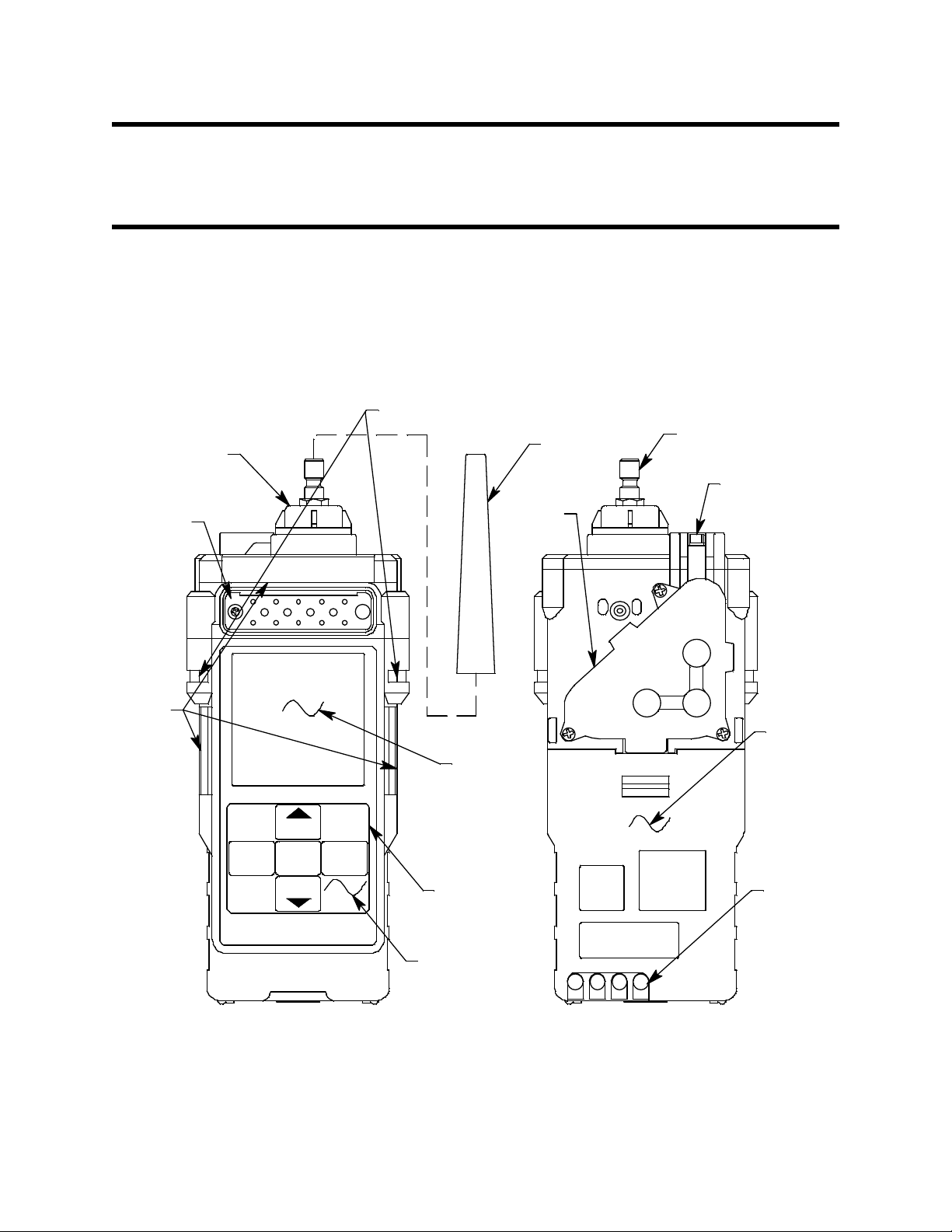
Chapter 2: Description
In l e t Fi ttin g
Exhaust
Tapered
Rubber
Nozzle
Battery
Cover
(alkaline
version)
Charging
Contacts
Inlet F i lter
Holder
Buzzer
Opening
RESET
SILENCE
DISPLAY
(ADJ)
AIR
(SHIFT)
POWER
ENTER
Wrist Strap Installation Feature
IR Port
(behind
button la bel)
Flow
Chamber
Control
Buttons
LCD
Alarm
LED
Arrays
Overview
This chapter describes the Gas Tracer instrument and accessories.
Instrument Description
The instrument includes the case, sensor, LCD, control buttons,
printed circuit boards, alarm LED’s, infrared communication port,
buzzer, vibrator, batteries, pump, flow chamber, and inlet filter
holder.
Figure 1: Components of the Gas Tracer, Front & Back
5 • Over view 10,000 ppm Gas Tracer Operator’s Manual
Page 13
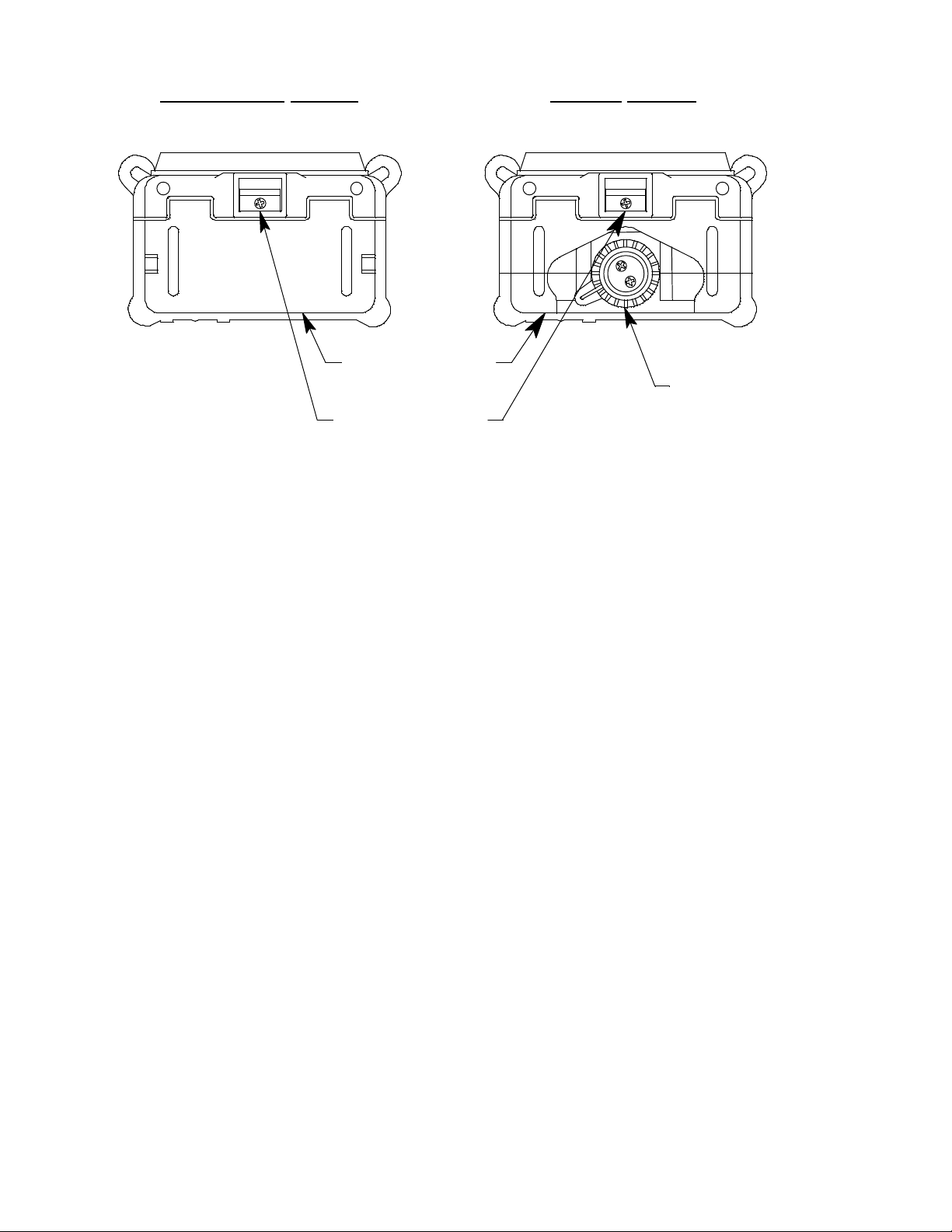
Case
Rechargeable Version
Battery Pack
Battery Pack
Release Latch
Battery Cover
Release Knob
Alkaline
Version
The Gas Tracer’s sturdy, high-impact plastic case is radio frequency
(RF) resistant and is suitable for use in many environmental
conditions, indoors and out. The case is dust proof and weather
resistant. A rubber layer on the outside of the case protects it from
scratches and impact damage.
A clear plastic window through which the LCD can be viewed is
located on the front of the case. Four brass charging contacts that are
used when the Gas Tracer is placed in the charging station are on the
back of the case. Both the rechargeable and alkaline version include a
removable battery pack. The battery pack release latch is on the
bottom. The alkaline battery version also includes a battery cover
release knob. The battery pack and flow chamber are located on the
back of the Gas Tracer. The inlet filter holder is located on the top of
the Gas Tracer case.
Sensor
Figure 2: Components of the Gas Tracer, Bottom
The Gas Tracer has only the ppm sensor installed. All other sensor
positions are filled with a dummy sensor. The ppm sensor is located
inside the Gas Tracer and is held in its socket by the flow chamber.
The ppm combustible sensor detects combustible gas in the ppm
range. It is a combination catalytic/MOS type sensor with a current
output. The current is amplified by the Gas Tracer’s circuitry,
converted to a measurement of combustible gas concentration, and
10,000 ppm Gas Tracer Operator’s Manual Instrument Description • 6
Page 14
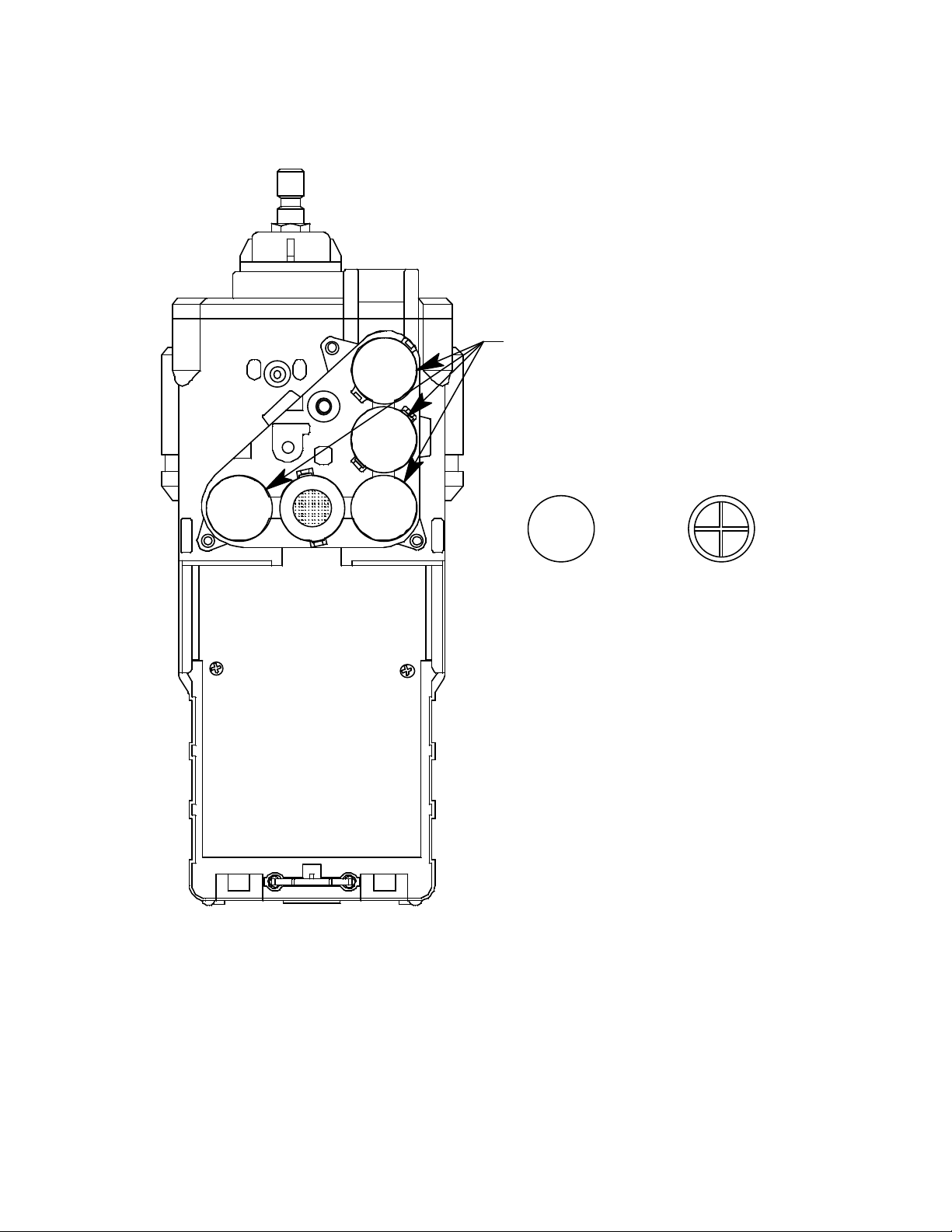
displayed on the LCD.
Bottom
Hollow Side
Top Flat
Side
Dummy Sensors
The Gas Tracer has 4 dummy sensors installed. Dummy sensors are factory
installed. The flat top of the dummy sensor should face up and the bottom
hollow side should face down.
Figure 3: Dummy Sensors
7 • I n s t r u m e n t D e s cri p t i o n 10,000 ppm Gas Tracer Operator’s Manual
Page 15

LCD
A digital LCD (liquid crystal display) is visible through a clear plastic
window on the front of the case. The LCD display shows the gas
reading. The display also shows information for each of the Gas
Tracer’s program modes.
Control Buttons
Five control buttons are located below the LCD. They are arranged
around a central button, the POWER ENTER button. The DISPLAY
(ADJ) button is on the left, the RESET SILENCE button on the right,
the AIR▲ button on the top, and the (SHIFT)▼ is on the bottom.
Table 2: Gas Tracer Control Button Functions
Button Function(s)
POWER ENTER • turns the Gas Tracer on and off.
• used during setup and calibration.
RESET SILENCE silences the audible alarm
DISPLAY (ADJ) • enters instructions into the Gas Tracer’s microprocessor
AIR▲ • activates the demand-zero function (automatically adjusts the
Gas Tracer in fresh-air conditions)
• scrolls through the settings modes
(SHIFT)▼ • scrolls through the settings modes
• enters instructions into the Gas Tracer’s microprocessor
Printed Circuit Boards
The Gas Tracer printed circuit boards analyze, record, control, store,
and display the information collected. The circuit boards are located
inside the case. They are not user serviceable.
Alarm LED Arrays
Three red alarm LED (light emitting diode) arrays are visible through
frosted plastic lenses in the case. One is on the top front, one on the
left side, and one on the right side. The alarm LED arrays alert you to
gas, low battery, and failure alarms.
Infrared Communications Port
An infrared (IR) communications port is located just below the RESET
SILENCE button. The signal goes through the control button material.
The data transmitted through the port is in standard IrDA protocol. A
computer’s infrared port or an IrDA/USB cable connected to a
computer’s USB port can be used to download data saved by the
10,000 ppm Gas Tracer Operator’s Manual Instrument Description • 8
Page 16

Gas Tracer to a computer using the GX-2012 Data Logger
Management Program. See the GX-2012 Data Logger Management
Program operator’s manual for data logging and downloading
instructions.
Buzzer
One solid-state electronic buzzer is located inside the case. Holes on
the top front of the case allow the sound to exit the case. The buzzer
sounds for gas alarms, malfunctions, low battery voltage, and as an
indicator during use of the Gas Tracer’s many display and adjustment
options.
Vibrator
A vibrating motor inside the Gas Tracer case vibrates for gas alarms,
unit malfunctions, and as an indicator during normal use of the
various modes of the Gas Tracer.
Batteries
Three AA-size alkaline batteries (standard) or an optional
rechargeable lithium ion battery pack (3.7 VDC) power the Gas Tracer.
Instrument run time is dependent upon battery type. At 25°C the
alkaline batteries last up to 15 hours and the lithium ion battery pack
lasts up to 10 hours. The battery icon in the upper right of the LCD
shows remaining battery life.
When the Gas Tracer detects a low battery voltage, a low battery
warning is activated. When battery voltage is too low for normal
operation, the Gas Tracer sounds a dead battery alarm.
The alkaline batteries can be replaced by removing the battery cover
on the back of the case. The lithium ion pack can be replaced by
removing the entire battery pack. Push the battery pack latch on the
bottom of the unit toward the front of the unit to release the pack.
The lithium ion battery pack can be recharged by placing the Gas
Tracer in its optional battery charging station or by placing the battery
pack in the charging station.
NOTE: Use of batteries or battery chargers not specified by RKI
Instruments, Inc. will void the CSA classification and may
void the warranty. See “Replacing or Recharging the
Batteries” on page 85.
9 • I n s t r u m e n t D e s cri p t i o n 10,000 ppm Gas Tracer Operator’s Manual
Page 17

WARNING: To prevent ign iti on of a hazard ous atmosph er e, batt eries
must only be changed or charged in an area known to be
nonhazardous.
Pump
A diaphragm pump inside the Gas Tracer draws the sample to the
sensors. It can draw sample from as far as 50 feet from the Gas Tracer.
The pump is not user serviceable.
CAUTION:Sample hose lengths of more than 50 feet are not recommended
for the Gas Tracer because of flow rate reduction.
Flow Chamber
The flow chamber is on the back of the Gas Tracer and is held in place
by three phillips screws. The flow chamber seals to the rubber sensor
gasket which seals to the sensor face inside the Gas Tracer and routes
flow from the pump to the sensor to the exhaust port (also a part of
the flow chamber).
Inlet Filter Holder
The filter holder is a clear plastic dome shaped piece on the top of the
case. A male quick connect fitting is located on the inlet filter holder.
This is the Gas Tracer’s inlet fitting. A cotton dust filter is inside the
filter holder. The filter holder may be removed by turning it
counterclockwise and pulling it away from the case. Two flat
membrane disk hydrophobic filters, a wire mesh disk, and a rubber
filter retaining gasket are held in place by the filter holder and are
located in the bottom of the case chamber where the filter holder is
installed.
Standard Accessories
The standard accessories include the tapered rubber nozzle, belt clip,
sample hose, and 10 inch probe.
Tap ered Rubber Nozzle
A cone shaped 4 inch long rubber nozzle is included with the Gas
Tracer as standard. It can be installed on the inlet fitting by pushing
the larger end over it. The smaller end can be inserted through a hole
in a wall or some other access to an enclosed area to sample the
environment.
10,000 ppm Gas Tracer Operator’s Manual Standard Accessories • 10
Page 18
Belt Clip
Sample Hose
Probe
A belt clip can be mounted to the back of the case using 3 phillips
head screws. The belt clip allows the Gas Tracer to be securely
attached to a belt.
Wri st Strap
A wrist strap is included with the Gas Tracer and can be attached to the right
or left wrist strap installation feature.
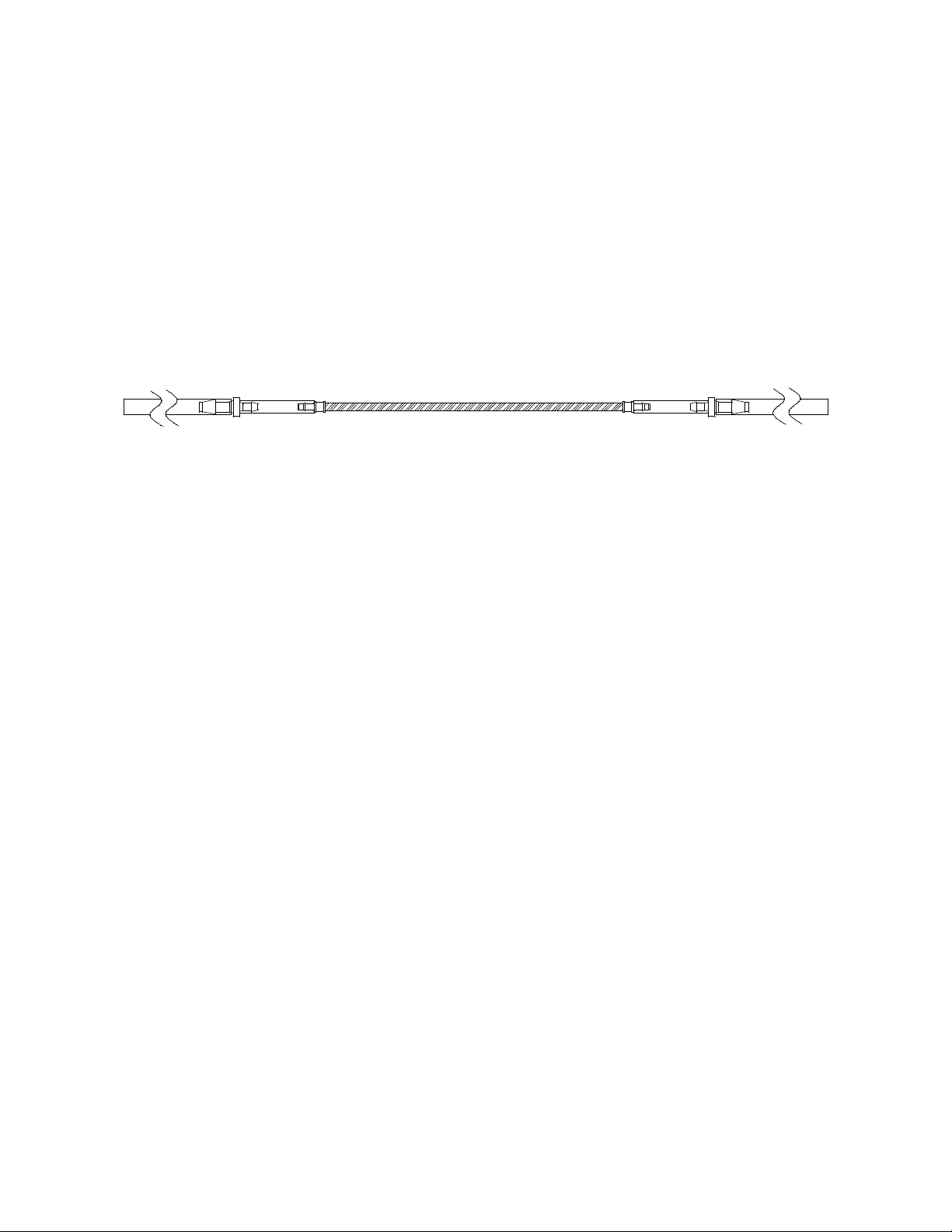
Sample Hose & 10 Inch Probe
A 10 foot sample hose and a 10 inch probe are included as standard
with the Gas Tracer . When desir ed, the rubber nozzle may be r emoved
and the sample hose and 10 inch probe may be connected to the inlet
fitting. Sample hose lengths are available from 10 feet to 50 feet (see
“Parts List” on page 95). The quick connect end of the sample hose
connects to the inlet fitting of the Gas Tracer and the probe screws
onto the end of the hose with the threaded fitting.
CAUTION:Sample hose lengths of more than 50 feet are not recommended
for the Gas Tracer because of flow rate reduction.
Figure 4: Sample Hose and Probe
Optional Accessories
Several optional accessories are available for the Gas Tracer. They
include a rechargeable lithium ion battery pack, battery charging
stations, and various special probes. The most commonly used
optional accessories are described below. Detailed instructions
regarding the use of these and other available accessories are included
in other parts of this manual. Data logging accessories are briefly
described in “Data Logging” on page 34.
11 • O p t i o n a l A c c e s s or i e s 10,000 ppm Gas Tracer Operator’s Manual
Page 19
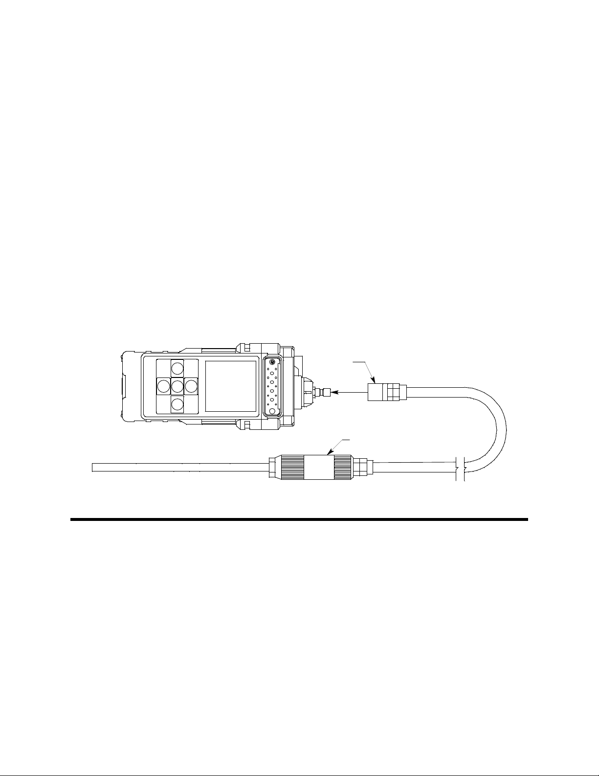
Rechargeable Lithium Ion Battery Pack
Charging
Contacts
Charge LED
AC Adapter
To AC
Outlet
Adapter Jack
Adapter Jack
Top
ViewRear Vi ew
A rechargeable lithium ion battery pack is available for the Gas Tracer .
A fully charged battery pack will power the Gas Tracer for 10 hours.
The batteries will last for a minimum of 500 charge cycles. See the
“Parts List” on page 95 for ordering information.
Charging Stations
The Gas Tracer lithium ion battery pack is charged with the Gas Tracer
charging station. Two battery charging stations are available for the
Gas Tracer, the standard AC charging station, and a DC charging
station with a vehicle plug adapter.
AC Powered Charging Station
The standard AC powered charging station consists of an instrument
charging base and an AC adapter. The AC adapter plugs into a 115
VAC wall outlet and connects to the charging station with a jack on
the end of a five foot DC output cable. The AC adapter will also work
for 100 VAC or 220 VAC if an appropriate plug adapter is provided.
The AC charging station is shown below in Figure 5.
Figure 5: Gas Tracer AC Powered Charging Station
10,000 ppm Gas Tracer Operator’s Manual Optional Accessories • 12
Page 20
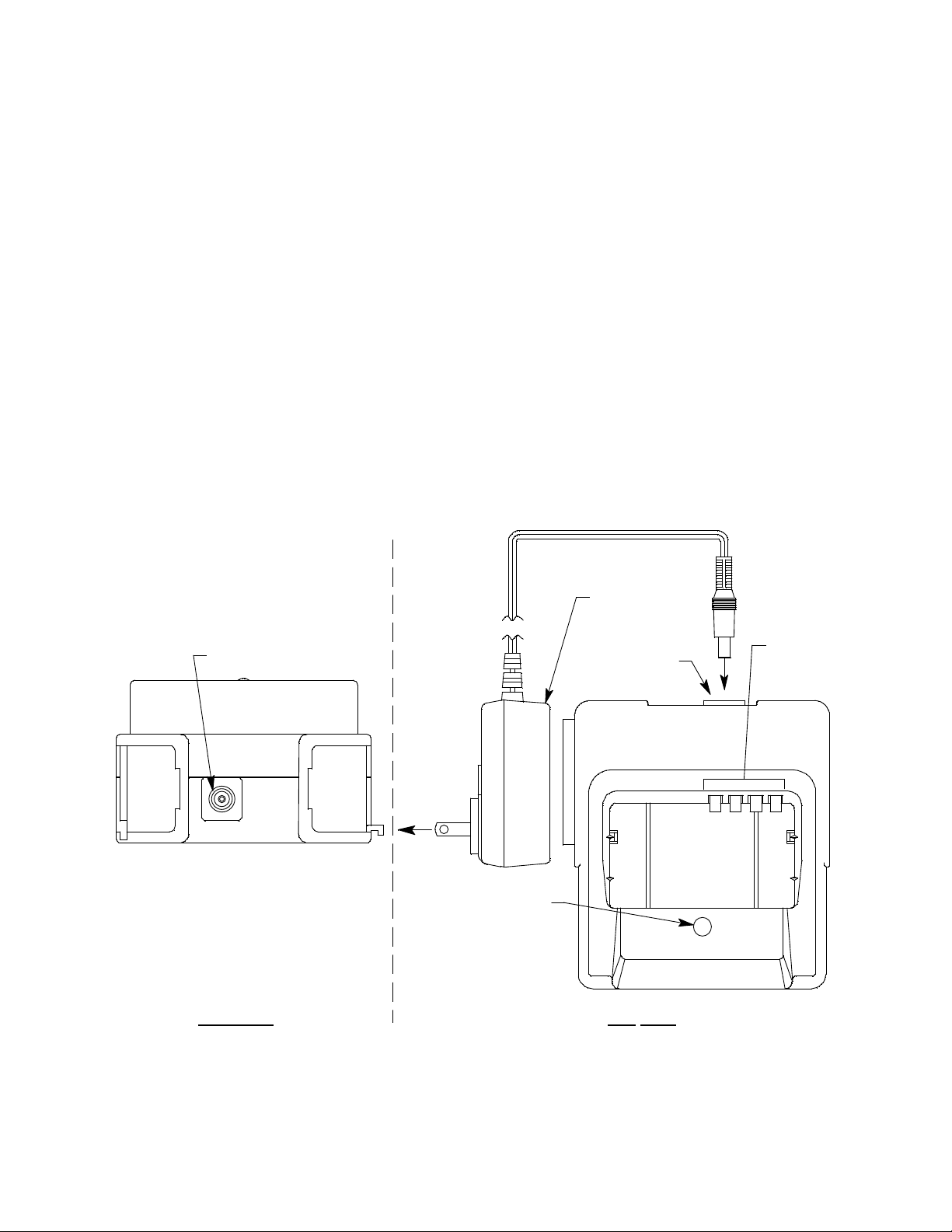
DC Powered Charging Station
Charging
Contacts
Adapter Jack
To Vehicle
12 VDC
Power Socket
Vehicle Plug
Adapter Jack
Rear View
Charge LED
Top
View
An optional DC powered charging station is available with a vehicle
plug 12 VDC adapter. It uses the same charging base as the AC
charging station but comes with a velcro strap to secure the Gas Tracer
in the charging base.
Optional Probes
Figure 6: Gas Tracer DC Powered Charging Station
Various optional probes designed for specific applications are
available for the Gas Tracer. They include the following:
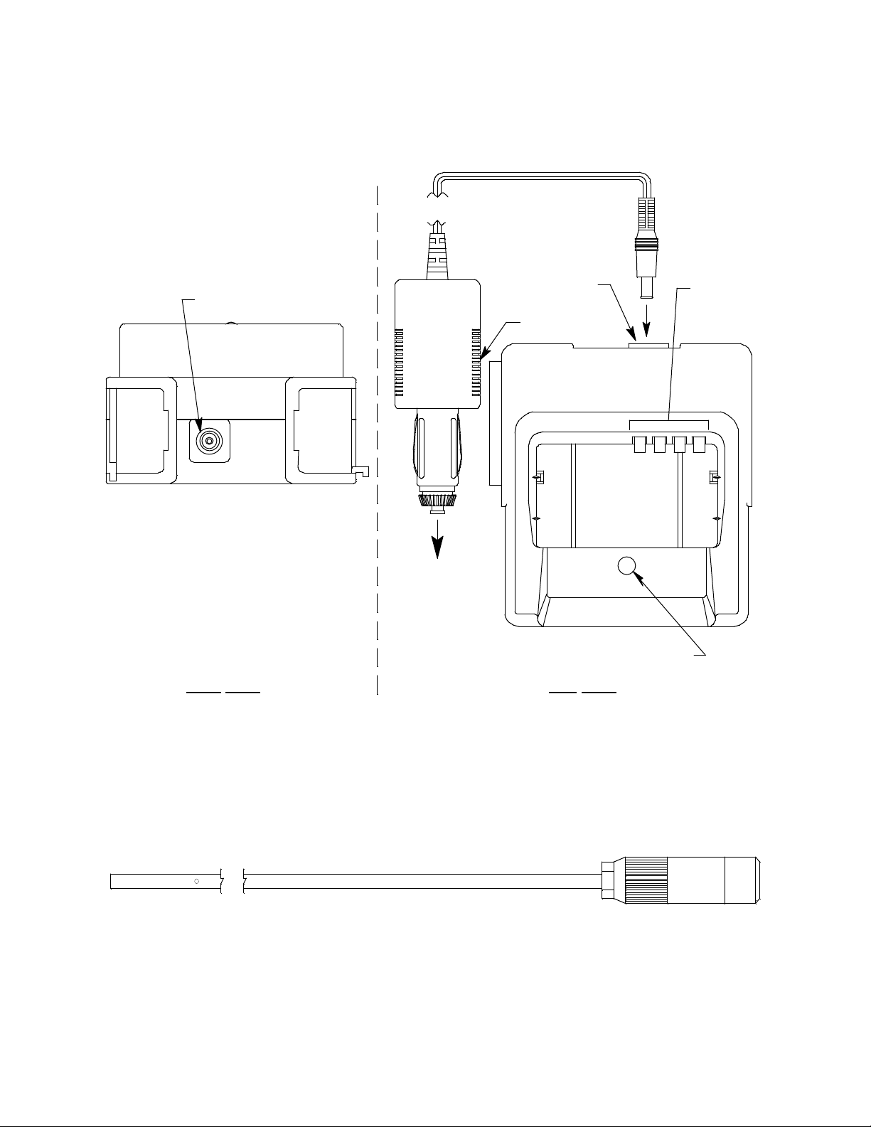
• 30 inch aluminum probe
Figure 7: 30 Inch Aluminum Probe
This probe is designed for applications where it is necessary to put
the probe tip in areas that are out of reach with the standard pr obe .
A small breather hole near the end of the probe tube prevents
13 • O p t i o n a l A c c e s s or i e s 10,000 ppm Gas Tracer Operator’s Manual
Page 21
interruption of sampling and a low flow alarm if the probe tip is
blocked.
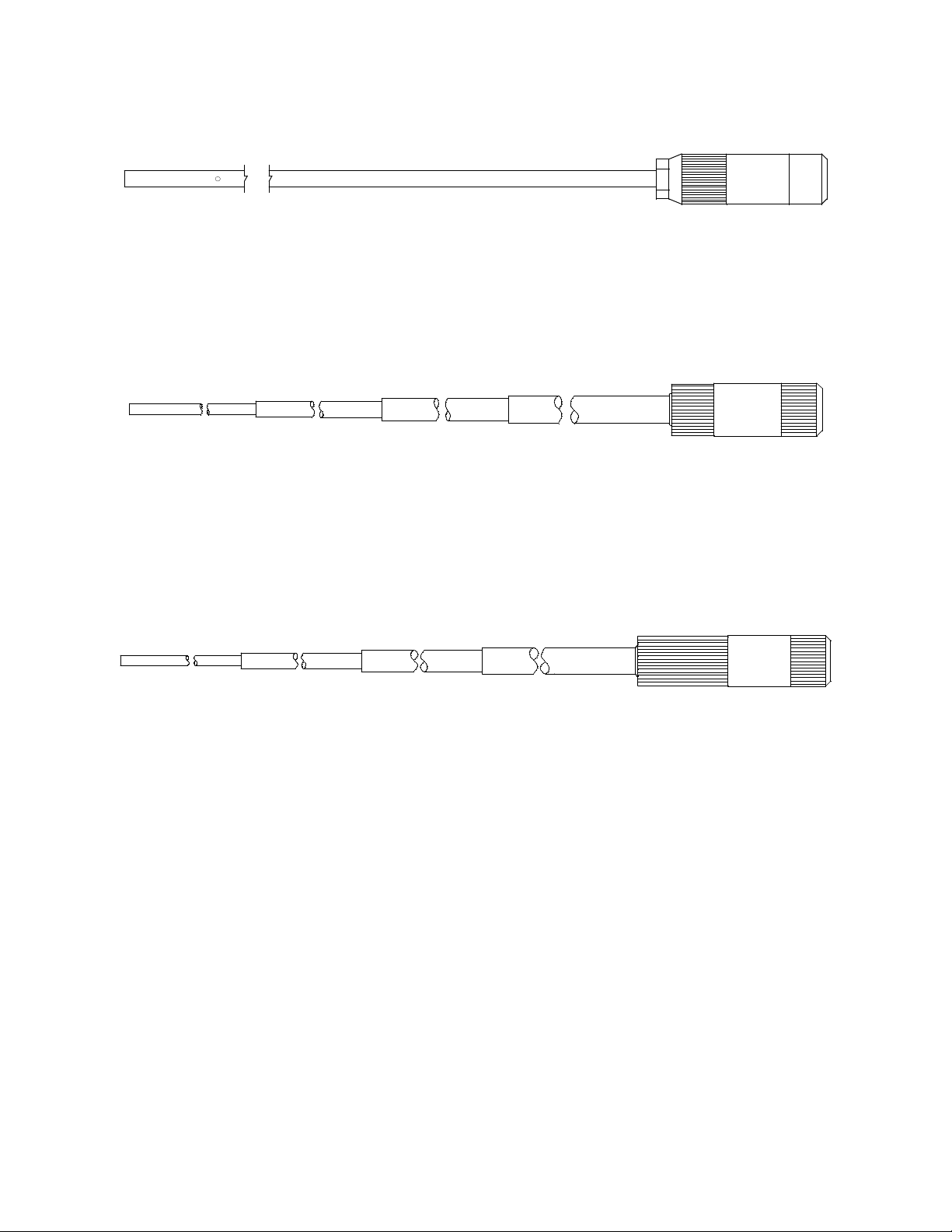
• 30 inch stainless steel probe
Figure 8: 30 Inch Stainless Steel Probe
This probe is physically the same as the 30 inch aluminum probe
and is intended for applications where a high level of corrosion
resistance is required in the long probe tube.
• 32 inch telescoping probe with dust filter
Figure 9: 32 Inch Telescoping Probe with Dust Filter
This probe is designed for use where it is necessary to put the
probe tip in areas not accessible with the 10 inch probe with dust
filter and applications where the pr obe tube must be collapsible for
storage.
• 7 foot telescoping probe with dust filter
Figure 10: 7 Foot Telescoping Probe with Dust Filter
This probe is designed for use where it is necessary to put the
probe tip in areas not accessible with the 32 inch telescoping probe
with dust filter and applications where the probe tube must be
collapsible for storage.
10,000 ppm Gas Tracer Operator’s Manual Optional Accessories • 14
Page 22
Humidifier Tube
A 6 inch humidifier tube comes with any calibration kits purchased
for the Gas Tracer. It is for use in calibrating the ppm combustible gas
sensor. If you did not purchase a calibration kit fo r the Gas Tracer and
purchased calibration cylinders independently, you will need to
purchase a humidifier tube in order to properly calibrate the ppm
combustible gas sensor. Use the humidifier tube to connect the ppm
calibration cylinder to the Gas Tracer. If you are using a zero air
cylinder to perform a fresh air adjustment on the ppm sensor in Leak
Check Mode or a WET fresh air adjustment in Calibration Mode, you
will need to use the humidifier tube to connect the zero air cylinder to
the Gas Tracer.
Figure 11: Humidifier Tube
NOTE: When removing the humidifier tube from the Gas Tracer or a
demand flow regulator, be sure to grasp it by the clear tubing
at the ends of the humidifier tube assembly, not the
humidifier tube itself.
15 • O p t i o n a l A c c e s s or i e s 10,000 ppm Gas Tracer Operator’s Manual
Page 23

Chapter 3: Start Up and Operation
Overview
This chapter explains how to operate the Gas Tracer. The Gas Tracer
only operates in Leak Check Mode and cannot be used in any other
mode. Leak Check Mode is used to pinpoint small leaks of
combustible gas fro m valves, flanges, connections , and other potential
leak points.
Start Up
This section explains how to start up the Gas Tracer and get it ready
for operation.
NOTE: The battery drain is higher in Leak Check Mode. Extended
operation in this mode will result in shorter battery life than
specified in “Specifications” on page 3.
Turning On the Gas Tracer
The following description of the Gas Tracer start up sequence assumes
that the following menu items in Maintenance Mode are set as
follows:
• ID DISP set to ON
• CL RMNDR set to ON
• BP RMNDR set to ON
• C--CHECK set to ALL
• B--CHECK set to ALL
If ID DISP, CL RMNDR, and BP RMNDR are turned off, or if C--
CHECK and B--CHECK are set to 4GAS then the corresponding
screen will not appear.
1. Connect the tapered rubber nozzle to the inlet fitting.
2. If a sample hose is used, connect the sample hose to the Gas
Tracer’s quick connect inlet fitting.
NOTE: If a probe is used when using the Gas Tracer, use the standard
probe or one of the probes described in “Optional Probes” on
page 13 or listed in the “Parts List” on page 95. Do not use the
bar hole probe.
10,000 ppm Gas Tracer Operator’s Manual Overview • 16
Page 24
3. Press and briefly hold down the POWER ENTER button.
CAL
C--LIMIT
FAIL
C--LIMIT
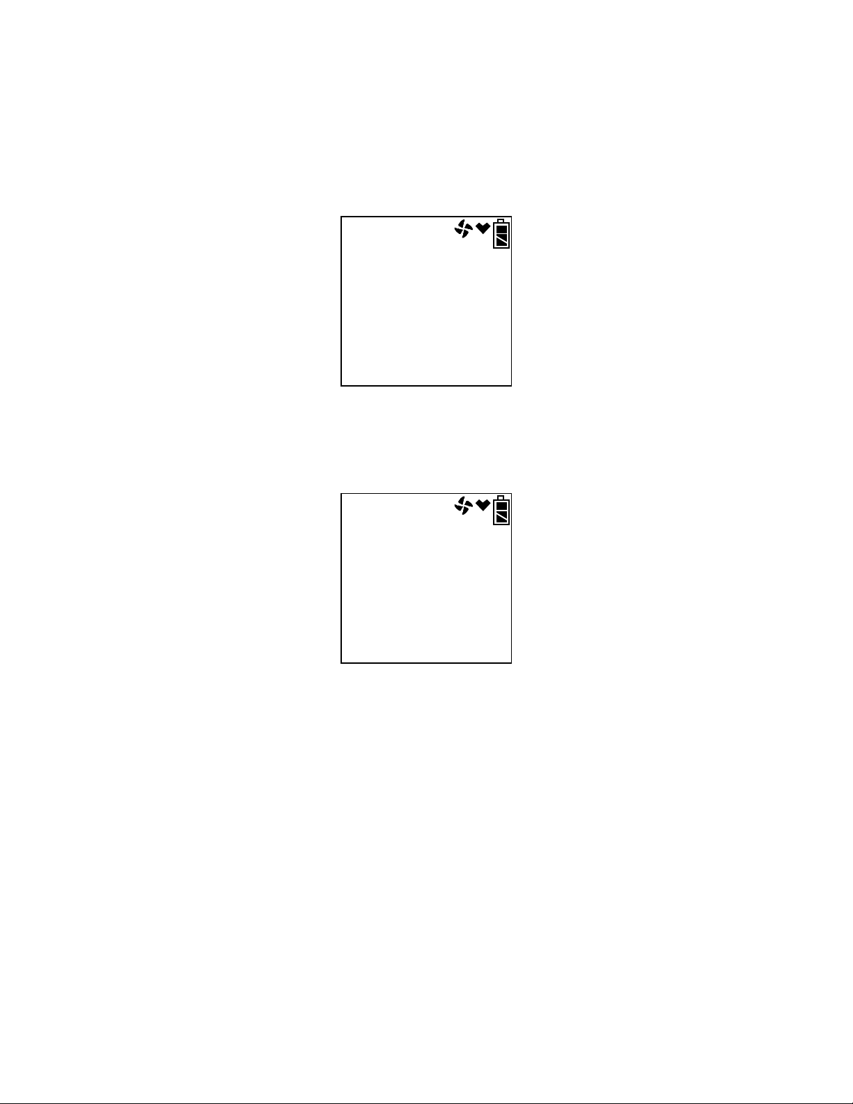
4. If CL RMNDR is turned on (factory setting is OFF), and
C--CHECK is set to ALL (factory setting), the screen that appears
next depends on how CL EXPRD is set in the Maintenance Mode
Menu (page 72).
• If the unit is due for calibration and CL EXPRD is set to
CONFIRM (factory setting), then the following screen displays.
The alarm LED’s and buzzer will pulse several times. After
this, press and release the RESET SILENCE button to continue.
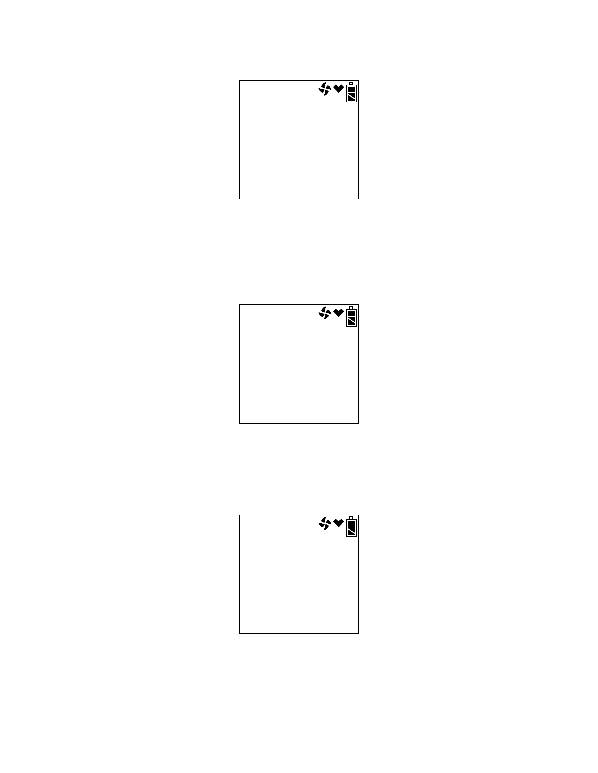
• If the unit is due for calibration and CL EXPRD is set to NOT
USE, then the following screen displays.
The Gas Tracer cannot be used until a calibration has been
performed either by selecting PPM CAL in the Maintenance
Mode menu. See “Calibrating and Bump Testing the PPM
Combustible Sensor” on page 54 for calibration instructions.
17 • S t a r t U p 10,000 ppm Gas Tracer Operator’s Manual
Page 25
• If calibration is not due or CL EXPRD is set to NO EFFECT,
2011
9
30
69d
NEXT CAL
tESt
B--LIMIT
FAIL
B--LIMIT
then the following screen appears for a few seconds indicating
when the next calibration is due.
5. If BP RMNDR is turned on (factory setting is OFF), and
B--CHECK is set to ALL (factory setting), the screen that appears
next depends on how BP EXPRD is set in the Maintenance Mode
Menu (page 72).
• If the unit is due for a bump test and BP EXPRD is set to
CONFIRM (factory setting), then the following screen displays.
The alarm LED’s and buzzer will pulse several times. After
this, press the RESET SILENCE button until you hear a beep to
continue.
• If the unit is due for a bump test and BP EXPRD is set to NOT
USE, then the following screen displays.
The Gas Tracer cannot be used until a bump test has been
performed by selecting PPM CAL in the Maintenance Mode
menu and then selecting BUMP. See “Performing a Bump
10,000 ppm Gas Tracer Operator’s Manual Start Up • 18
Page 26
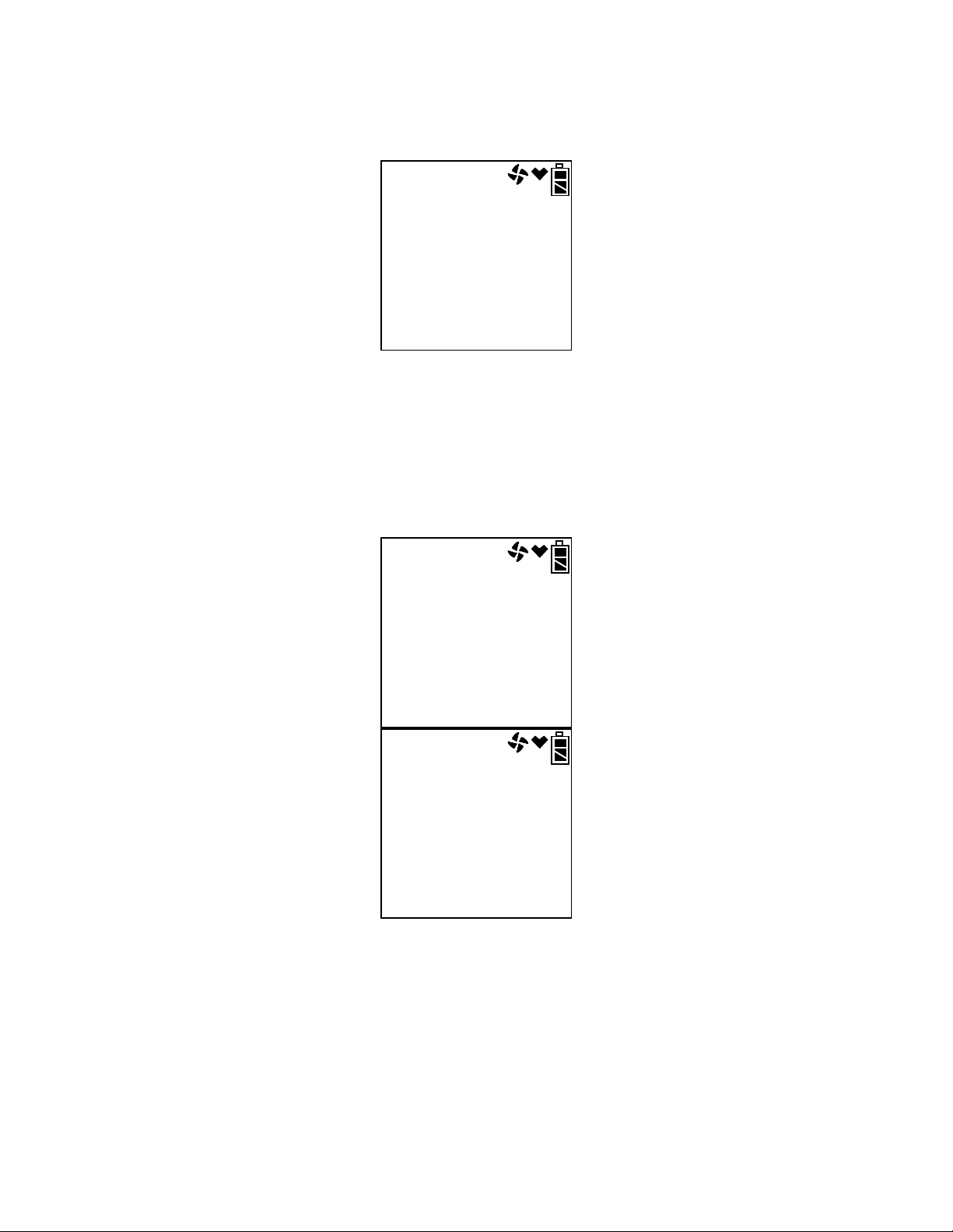
Test” on page 54 for bump testing instructions.
2011
9
30
10d
NEXTBUMP
U Id
- - - - - - - -
S Id
- - - - - - - -
• If a bump test is not due or BP EXPRD is set to NO EFFECT,
then the following screen appears for a few seconds indicating
when the next bump test is due.
NOTE: If both CL RMNDR and BP RMNDR are turned off, a W ARM
UP screen will display before the warm up sequence
continues.
6. If ID DISP is turned on (see page 77), the User ID Screen displays
for a few seconds and then the Station ID Screen displays for a few
seconds.
19 • S t a r t U p 10,000 ppm Gas Tracer Operator’s Manual
Page 27

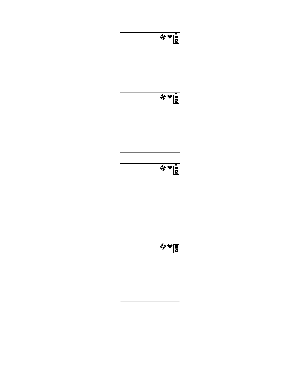
7. The Date/Time Screen appears for a few seconds.
2011
8
31
22:39
DATE
bAtt
3.7
AL-H V
bAtt
3.7
AL-H D: V
This screen displays the current year, month, date, and time.
8. The Battery Level and Alarm Pattern Screen appears next.
AL -- H indicates latching (hold) alarms and AL -- A indicates selfresetting (automatic) alarms. The number shown indicates the
voltage of the batteries. If the unit is powered by alkaline (dry cell)
batteries, a “D” will appear before the “V” in the lower right
corner.
10,000 ppm Gas Tracer Operator’s Manual Start Up • 20
Page 28
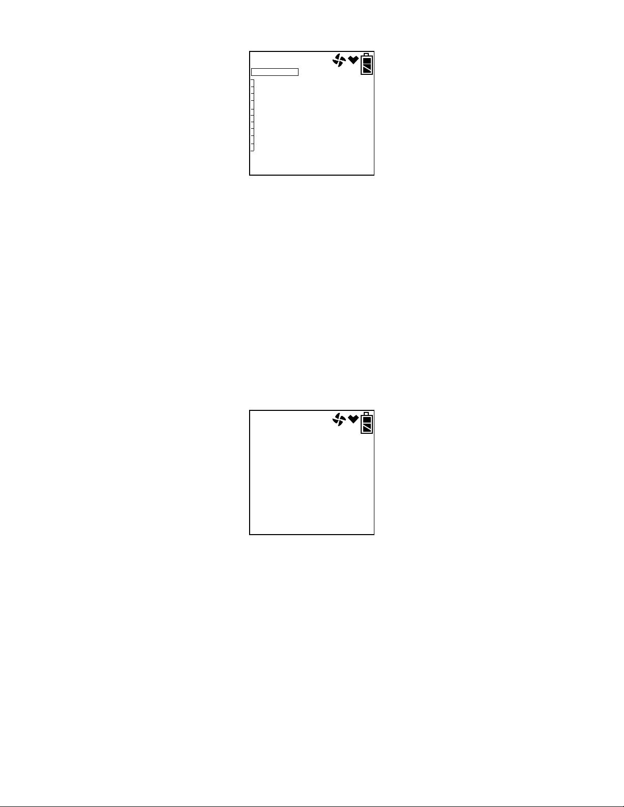
9. The display then indicates the detection units and then the full
CH4
ppm
CH4
9990
ppm
CH4
F.S.
15
sec
WARM UP
FAIL
ppm
CH4
SENSOR
scale values for the ppm channel.
10.The Gas Tracer will then continue its warm up.
21 • S t a r t U p 10,000 ppm Gas Tracer Operator’s Manual
11.If the Gas Tracer experiences a sensor failure during start up, a
screen indicating the sensor failure displays.
If the ppm sensor fails, the Gas Tracer cannot be used. Use the
POWER ENTER button to turn the Gas Tracer off. Replace the
failed sensor as soon as possible.
Page 29
12.The Gas Tracer is now operating in Leak Check Mode.
0
9990
ppm
ppm
LEAK CK MODE
CH4
F.S.
AIr
CAL
HOLD AIR
The combustible gas reading is displayed along with the battery
charge level.
Performing a Fresh Air Adjustment
Before using the Gas Tracer for leak checking, it is recommended to
set the fresh air reading by performing a fresh air adjustment. This
will set the combustible gas channel to zero.
1. Find a fresh-air environment. This is an environment free of toxic
or combustible gases and of normal oxygen content (20.9%).
2. Turn on th e unit as described above in “Turning On the Gas Tracer”
on page 16.
3. Press and hold the AIR▲ button. The display will prompt you to
hold the AIR▲ button.
4. Continue to hold the AIR▲ button until the display prompts you to
release the AIR▲ button. The Gas Tracer will set the fresh air
reading for the combustible channel. Once the fresh air adjustment
has finished, start up is complete and the unit is ready for leak
testing.
5. If you would like to calibrate the Gas Tracer while in Leak Check
Mode, follow the same instructions described in “Calibration
Mode” on page 35.
10,000 ppm Gas Tracer Operator’s Manual Start Up • 22
Page 30

Alarm Indications
NOTE: False alarms may be caused by radio frequency (RF) or
electromagnetic (EMI) interferen ce. Keep the Gas Tracer away
from RF and EMI sources such as radio transmitters or large
motors.
When a failure condition occurs, such as a sensor failure, low flow, or
dead battery condition, the unit will also sound an alarm, flash the
LED arrays, and vibrate.
The table below summarizes the types of alarms produced by the
Gas Tracer.
Alarm Type Visual Indications Other Indications
Table 3: Alarm Types and Indications
Gas Level
Indications
Over Scale
Low Flow*
Low Battery
Warning*
Dead Battery Alarm
• The numerical reading
and the bar graph
level will increase as
the gas level
increases.
• See “Overscale
Condition” on page 27
for a description of the
Overscale alarm
visual indications.
• The display indicates
FAIL LOW FLOW
• The Alarm LED’s flash
• Battery icon blinks • None
• Gas readings
replaced by FAIL
• Fan symbol
disappears
• BATTERY displayed
along bottom of
screen
• Alarm LED arrays
flash
• The beeping and
buzzer pulsing
frequency will
increase as the gas
level increase s.
• See “Overscale
Condition” on page 27
for a description of all
other Overscale alarm
indications.
• Buzzer sounds a
double pulsing tone
(two pulses in quick
succession)
Buzzer sounds a double
pulsing tone (two pulses
in quick succession)
23 • A l a r m I n d i c a t io n s 10,000 ppm Gas Tracer Operator’s Manual
Page 31

Table 3: Alarm Types and Indications
Alarm Type Visual Indications Other Indications
Sensor Failure
Clock Failure
System Failure
Microprocessor
Failure
• NOTE: The unit will
not operate if this
alarm occurs.
• FAIL appears at the
bottom of the display
and the failed sensor
is indicated
• Alarm LED arrays
flash
• FAI L CLOCK appears
on the display
• Alarm LED arrays
flash
• FAIL SYSTEM
appears on the
display
• Alarm LED arrays
flash
• Heart indicator is
steadily on or not on
at all
Buzzer sounds a double
pulsing tone (two pulses
in quick succession)
Buzzer sounds a double
pulsing tone (two pulses
in quick succession)
• Buzzer sounds a
double pulsing tone
(two pulses in quick
succession)
• A failure code appears
• None
Responding to Alarms
This section describes response to battery, sensor, clock, system, and
microprocessor failure alarms.
Responding to Battery Alarms
WARNING: The Gas Tracer is not operational as a gas monitoring
device during a dead battery alarm. Take the Gas Tracer
to a non-hazardous area and replace or recharge the
batteries as described in “Replacing or Recharging the
Batteries” on page 85.
The Gas Tracer is fully functional during a low battery warning.
However, only a limited amount of operating time remains,
approximately 1 - 2 hours. The amount of time depends on how often
the LCD backlight is used and how often the unit is responding to
alarm conditions. Recharge the battery pack or replace the alkaline
batteries as soon as possible as described in “Replacing or Recharging
the Batteries” on page 85.
10,000 ppm Gas Tracer Operator’s Manual Responding to Alarms • 24
Page 32

NOTE: Alarms and the back li ght featur e consume bat tery power and
FAIL
031
SYSTEM
reduce the amount of operating time remaining.
Responding to Sensor Failure Alarms
1. Try calibrating the ppm sensor first, as described in “Calibration
Mode” on page 35 before replacing it.
2. If the sensor failure continues, replace the ppm sensor as described
in “Replacing a Sensor” on page 92.
3. If the sensor failure condition continues after you have replaced the
sensor, contact RKI Instruments, Inc. for further instructions.
Responding to Clock Failure Alarm
This alarm occurs if the internal unit date has been changed to
something unreasonable like 15/34 (month/day).
1. Press and release the RESET SILENCE button to continue into
normal operation.
CAUTION:There will be no datalogging function if you operate the
instrument after a clock failure.
2. Attempt to change the date using the DATE menu time in
Maintenance Mode. See “Updating the Date and Time Settings” on
page 53.
3. If the date cannot be set correctly, contact RKI Instruments, Inc. as
soon as possible.
Responding to System Failure Alarms
1. If a system failure occurs, the system failure screen will display an
error code as shown below:
25 • R e s p o n d i n g t o A l ar m s 10,000 ppm Gas Tracer Operator’s Manual
Page 33

2. The error code meanings are shown below:
Table 4: Error Code Explanation
Error Code Explanation
000 MPU failure
010 RAM failure
021 EEPROM failure
031 FLASH memory failure
3. If the error code is anything but 031 as shown above, the
instrument cannot be used. Contact RKI Instruments, Inc. as soon
as possible.
If the error code is 031, you may press and release the RESET
SILENCE button to continue to normal operation if the instrument
must be used temporarily.
CAUTION:There will be no datalogging function if you operate the
instrument after a 031 system failure. Contact RKI
Instruments, Inc. as soon as possible.
Responding to Microprocessor Failure
If your unit experiences a microprocessor failure, the heart symbol at
the top of the screen will be steadily on or steadily of f. The unit cannot
be used in this case. Contact RKI Instruments, Inc. as soon as possible.
Leak Testing
The increment of the reading is always 10 ppm but the display range
can be adjusted by using the DISPLAY (ADJ) button. The display
range choices are 1000 ppm, 2000 ppm, 4000 ppm, and 9990 ppm. The
readings are displayed in both numerical and bar graph form. As the
gas concentration increases from 0 ppm, the alarm LEDs begin to
blink in unison with the buzzer’s pulsing. The blinking/pulsing rate
increases as the gas reading increases. If desired the buzzer can be
turned off in Leak Check Mode.
In a low-light environment, press and release any of the buttons to
turn on the display backlight. See “Updating the LCD Back Light
T ime Setting” on page 77 to program backlight duration. If BEEP. SET
is turned on in Maintenance Mode, the Gas Tracer beeps once every 5
minutes to confirm that it’s operating.
10,000 ppm Gas Tracer Operator’s Manual Leak Testing • 26
Page 34

Setting the Display Range Value
0
1000
ppm
ppm
LEAK CK MODE
CH4
F.S.
The Gas Tracer Leak Check Mode has 4 display range ppm values to
choose from: 1000 ppm, 2000 ppm, 4000 ppm, and 9990 ppm.
NOTE: The Gas T racer is always detecting combustible gas up to 9990
ppm. The display range value is only adjusting what part of
the detection range is displayed on the LCD.
To change the display range value:
1. While in Leak Check Mode, press and release the DISPLAY (ADJ)
button. The display range value displayed along the bottom of the
screen will change.
Continue to press and release the DISPLAY (ADJ) button until the
desired display range value is displayed.
2. The unit is now operating with the selected display range.
Locating a Leak
1. Start up the Gas Tracer as described above in “Turning On the Gas
Tracer” on page 16.
2. Move the probe tip or tapered nozzle tip back and forth along the
area where a leak is suspected.
3. Observe the display reading. If the gas level increases, the
numerical reading will increase, the bar graph level will increase,
and the beeping and buzzer pulsing frequency will increase.
4. Y our gas reading may exceed your display range. For a description,
see the following section.
5. Use the increasing and decreasing of the reading to locate the leak
point.
Overscale Condition
The Gas Tracer may experience an overscale condition while
operating in Leak Check Mode.
27 • L e a k T e s t i n g 10,000 ppm Gas Tracer Operator’s Manual
Page 35

If you are using a display range of 1000, 2000, or 4000 ppm and the gas
9990
9990
ppm
ppm
LEAK CK MODE
CH4
OVER
level goes above the display range, the full scale value of the display
range will be displayed but it will not be an overscale condition unless
the gas level is above 9990 ppm. If the gas level exceeds 9990 ppm, the
display will indicate an overscale alarm and the ppm sensor will be
shut off.
Press and release the RESET SILENCE button. The ppm sensor will
enter a 30 second warm up period while the ppm sensor turns on
again.
Turning the Alarm On and Off
The alarm buzzer can be turned off and on when the Gas Tracer is in
Leak Check Mode. When the buzzer is set to Off, NO ALARM
appears in the upper left hand corner of the display. If the buzzer is
turned off, then it will remain off in Leak Check Mode even if you
turn the unit off and on unless the buzzer is manually turned on.
To turn the buzzer off or on while in Leak Check Mode:
1. Press and hold the DISPLAY(ADJ) button for 5 seconds.
NOTE: Pressing and holding the DISPLAY (ADJ) button will change
the full scale setting for Leak Check Mode. Once you have
made your buzzer selection, use the DISPLAY (ADJ) button to
display the desired full scale.
2. Release the button when NO ALARM in the upper left corner
appears or disappears.
Snap Log Mode
The snap logging function in Snap Log Mode allows the user to rec ord
data at a specific time and have it saved to the data logger. The data is
assigned a snap log ID and is saved with the station ID that was
selected when the data was taken.
To enter Snap Log Mode and record snap log data:
1. Turn the Gas Tracer on as described in “Turning On the Gas T racer”
10,000 ppm Gas Tracer Operator’s Manual Leak Testing • 28
Page 36

on page 16. Select the desired display range. In the example below,
S Id
001
SEL
0
1000
ppm
ppm
LEAK CK MODE
CH4
BASE
1000 ppm has been selected. Press and hold the (SHIFT)T button,
then press and hold the AIRS button and hold both until you hear
a beep. The Station ID Select Screen will display and the current
station ID will be flashing.
2. Use the (SHIFT)T and AIRS buttons to scr oll to the desir ed station
ID, then press and release the POWER ENTER button to continue
to the Base Reading Screen. To return to the Station ID Select Screen
without taking a base reading, press and release the RESET
SILENCE button.
3. In order to get a base, or background, reading, take the instrument
a few feet away from where you intend to test. To save the base
reading, press and release the POWER ENTER button.
29 • L e a k T e s t i n g 10,000 ppm Gas Tracer Operator’s Manual
Page 37

NOTE: If the gas concentration exceeds the display range value
0
1000
ppm
ppm
LEAK CK MODE
CH4
PEAK
PEAK
without exceeding 9990 ppm, the full scale display range
value will be displayed but the actual gas reading at that time
will be recorded when you pre ss and release POWER ENTER.
For example, if the display range is 1000 ppm but the gas level
is 2300 ppm, the display will read 1000 ppm but the
instrument will save a reading of 2300 ppm.
If the gas concentration exceeds 9990 ppm in the Base
Reading Screen, the instrument will go into an overscale
alarm and turn off the ppm sensor in order to protect it. The
full scale display range value will be displayed but OVER will
be recorded when you press POWER ENTER. The full scale
display range value will continue to be displayed in the Peak
Reading Screen and OVER will again be recorded when you
press POWER ENTER. The instrument will then enter a 30
second warm up period in order to turn the ppm sensor on
again.
4. The unit will display SAVED along the bottom of the screen before
continuing to the Peak Reading Screen.
5. Take the instrument to the monitoring area. The instrument will
retain and display the highest gas concentration encountered. To
save the peak reading, press and release the POWER ENTER
button. The reading on the screen (the highest concentration
encountered) will be saved.
10,000 ppm Gas Tracer Operator’s Manual Leak Testing • 30
Page 38

NOTE: If the gas concentration exceeds the display range without
exceeding 9990 ppm, the full scale display range value will be
displayed but the actual gas reading at that time will be
recorded when you press and release POWER ENTER. For
example, if the display range is 1000 ppm but the gas level is
2300 ppm, the display will read 1000 ppm but the instrument
will save a reading of 2300 ppm.
If the gas concentration exceeds 9990 ppm in the Peak
Reading Screen, the instrument will go into an overscale
alarm and turn off the ppm sensor in order to protect it. The
full scale display range value will be displayed and OVER
will be recorded when you press POWER ENTER. The
instrument will then enter a 30 second warm up period in
order to turn the ppm sensor on again.
The unit will display SAVED along the bottom of the screen before
returning to the Station ID Select Screen.
To return to the Station ID Select Screen without taking a peak
reading, press and release the RESET SILENCE button.
6. Repeat steps 2 through 5 to take additional snap log data.
7. To exit Snap Log Mode at any time without taking a snap log or
when you are finished recording snap logs, press and release the
DISPLAY (ADJ) button. The unit will immediately return to the
Normal Operation Screen.
8. The data recorded in Snap Log Mode can be viewed in Display
Mode.
Viewing Snap Log Data
Snap log data can be viewed while in Leak Check Mode.
1. Turn the Gas Tracer on as described in “Turning On the Gas T racer”
on page 16.
2. Press and hold the RESET SILENCE button and then press and
hold the DISPLAY (ADJ) button and release both.
31 • L e a k T e s t i n g 10,000 ppm Gas Tracer Operator’s Manual
Page 39

3. If no snap logs have been performed, the following screen will
NO DATA
2012
2
15
14:17
LEAK CK MODE
M009
appear. Press and release the DISPLAY (ADJ) button to return to
Leak Check Mode.
4. If snap logs have been performed, the following screen will appear.
LEAK CK MODE will appear in the upper left corner to indicate
that the snap log was taken during Leak Check Mode Operation.
This screen indicates the year, month, day, and time that the most
recent snap log was taken. The number along the bottom of the
screen indicates the snap log ID number. The first snap log that is
taken is given an ID of M001. The next snap log ID is M002. The ID
number increases sequentially with each set of snap log data. Use
the AIR▲ and (SHIFT)▼ buttons to scroll through different snap
log IDs and view what time and day they were taken. Snap log
data that was taken in Leak Check Mode operation will have two
snap log ID numbers. One number is for the base reading and the
other is for the peak reading.
10,000 ppm Gas Tracer Operator’s Manual Leak Testing • 32
Page 40

5. To view the data in a snap log ID, press and release the POWER
2012
2
15
14:17
LEAK CK MODE
M009
2012
2
15
14:18
LEAK CK MODE
M010
POWER
4500
5000
ppm
ppm
LEAK CK MODE
CH4
VALVE 3
PEAK
0
5000
ppm
ppm
LEAK CK MODE
CH4
VALVE 3
ENTER
POWER
ENTER
Leak Check
Mode Operation
Leak Check
Mode Operation
Peak Data
Base Data
AIR▲
(SHIFT)▼
ENTER button. You can also go back and forth between the ID and
data screens by pr essing an d r eleasing the POWER ENTER button.
The gas readings that wer e taken during the snap log ar e displayed
and the Station ID that was in use during the snap log is displayed
along the bottom of the screen. Snap log data that was taken in
Leak Check Mode operation will have 2 sequential screens that are
part of one data set. One screen is for the base reading and the
other screen is for the peak reading. The peak reading value will
have PEAK displayed below the peak bar. If a base data point
appears without a peak data point after it, it is because a peak data
point was not taken. You can use the AIR▲ and (SHIFT)▼ buttons
to scroll through the different snap logs. The gas readings and
station ID will change but the snap log ID is not visible from this
screen.
6. To exit snap log data viewing and return to Leak Check Mode
Operation, press and release the DISPLAY (ADJ) button.
Turning Off the Gas Tracer
1. Press and hold the POWER ENTER button.
2. The buzzer will pulse for about three seconds and TURN OFF will
appear at the bottom of the screen.
33 • L e a k T e s t i n g 10,000 ppm Gas Tracer Operator’s Manual
3. Release the button when TURN OFF disappears.
Page 41

Data Logging
The Gas Tracer features the ability to log data to its internal memory
and download it to a computer via the infrared communications port
located just below the RESET SILENCE button. It logs bump test data,
calibration data, and event data. No interval trend or alarm trend data
is saved.
NOTE: Although interval trend and alarm trend data are not saved,
the Gas Tracer saves snap log data. For a description of the
snap logging function, see “Snap Log Mode” on page 28.
To utilize the Gas Tracer’s downloading capability, you will need the
Gas Tracer downloading software and a computer with an infrared
port or a USB port that runs one of the following operating systems:
Windows XP, Windows Vista or Windows 7. If your computer has an
infrared port, then no additional accessories are needed to download
data from the Gas Tracer. If your computer does not have an infrared
port but does have a USB port, a USB/IrDA adapter cable can be used
to download data from the Gas Tracer using a USB port. The
downloading software is available from RKI Instruments, Inc. The
adapter cable is also available from RKI or may be purchased at a
computer or electronics supply store.
For a complete description of the downloading software and
procedures for downloading data to a computer, see the GX-2012 Data
Logger Management Program Operator’s Manual.
SDM-2012
The Gas Tracer can be used with the SDM-2012 if desired. The SDM2012 can charge the instrument if the lithium ion battery pack is being
used. It can also bump test, calibrate, and retrieve saved data. The
SDM-2012 can be operated as a single, stand-alone unit or can be used
with up to 9 other SDM-2012s and operated using a computer. For
more information about the operation of the SDM-2012, see the SDM2012 Standalone Configuration Operator’s Manual or the SDM-2012
PC Controlled Configuration Operator’s Manual.
10,000 ppm Gas Tracer Operator’s Manual Data Logging • 34
Page 42

Calibration Mode
Calibration mode allows you to calibrate and bump test the PPM
sensor.
The optimum frequency of calibration depends heavily on how the
Gas Tracer is used. For example, instruments used daily may need to
be calibrated weekly or monthly, while instruments that are used only
a few times a year may need to be calibrated before each use. Typical
calibration frequencies range from monthly to quarterly.
You can program the Gas Tracer to notify you when it is due for
calibration. See “Updating the Calibration Reminder Setting” on
page 72.
Calibration/Bump Test Supplies and Equipment
To calibrate or bump test the Gas Tracer, you will need:
• Known calibrating sample of ppm methane gas
• A demand-flow regulator to provide adequate sample gas flow
• Non-absorbent tubing
• 6-inch humidifier tube
CAUTION:If you are using a calibration kit that includes a gas bag and a
fixed flow regulator or dispensing valve, do not apply gas
directly to the Gas Tracer with the regulator or valve or damage
to the pump will result. See “Appendix A: Calibrating or Bump
Testing with a Sample Bag” on page 97 for instructions to
properly use a gas bag kit.
Preparing for Calibration or Bump Test
Whether you will calibrate the Gas Tracer or perform a bump test, you
will need to set the fresh air readings first.
1. Find a fresh-air environment. This is an environment free of toxic
or combustible gases and of normal oxygen content (20.9%).
2. Turn on the unit as described in “Turning On the Gas Tracer” on
page 16. Use the sample hose and probe.
35 • C a l i b r a t i o n Mod e 10,000 ppm Gas Tracer Operator’s Manual
Page 43

3. With the unit on, perform a fresh air adjust by pressing and
AIr
CAL
MAINTENANCE
HOLD AIR
Err
PASSWORD
holding the AIR▲ button. The display prompts you to hold the
AIR▲ button.
4. Continue to hold the AIR▲ button until the display prompts you to
release it. The Gas Tracer will set the fresh air reading.
5. Install the demand flow regulator onto the calibration cylinder.
6. Connect the sample tubing to the demand flow regulator.
Calibrating and Bump Testing the PPM Combustible
Sensor
When calibrating the ppm sensor, a 6 inch humidifier tube must be
used to connect the zero air cylinder (if used for a WET fresh air
adjustment) and the ppm calibration cylinder to the instrument.
From Leak Check Mode, enter Calibration Mode by pressing and
holding the (SHIF T)▼ button, then pressing the DISPLAY(ADJ) button
and releasing both. If the unit prompts you for the password, enter it
by using the AIR▲ and (SHIFT)▼ buttons to select each password
number and then pressing and r eleasing POWER ENTER to confirm it
and move on to the next number. To go back a number, press and release
the RESET SILENCE button. The factory set password is the same as
the factory set password for Maintenance Mode: 2102. Y ou can change
the password by entering the PASSWORD menu item in
Maintenance Mode. See “Turning the Password Function On or Off”
on page 79. If you enter an incorrect password, an error screen will
display.
10,000 ppm Gas Tracer Operator’s Manual Calibration Mode • 36
Page 44

To return to normal operation, press and release the RESET SILENCE
MAINTENANCE
AIR CAL
button. You may then try to reenter Calibration Mode.
MAINTENANCE will appear along the top of the screen once you
have entered Calibration Mode. The first item in the calibration menu,
AIR CAL, displays.
The recommended calibration sequence for a quarterly calibration is
WET fresh air adjustment, WET span adjustment. The recommended
calibration sequence for a biannual calibration (every 6 months) is
DRY fresh air adjustment, WET fresh air adjustment, WET span
adjustment.
Performing a Wet Fresh Air Adjustment
This section describes how to perform a fresh air adjustment on the
PPM combustible gas sensor using the WET setting. Using the WET
setting and fresh air or a zero air cylinder with a 6 inch humidifier is
appropriate for a quarterly calibration.
NOTE: It is recommended that you perform a fresh air adjust on the
ppm sensor using a zero air cylinder and the DRY setting
once every 6 months to maintain the accuracy of the ppm
combustible gas reading. When performing a DRY fresh air
adjustment, be sure to not use the humidifier tube. See
“Performing a Dry Fresh Air Adjustment” on page 39 for
instructions to perform a dry fresh air adjustment.
37 • C a l i b r a t i o n Mod e 10,000 ppm Gas Tracer Operator’s Manual
Page 45

1. If you did not perform a fresh air adjustment while in Leak Check
MAINTENANCE
AIR CAL
MAINTENANCE
WET
50
ppm
MAINTENANCE
CH4
PUSH AIR
Mode, you must perform one before performing an auto
calibration, a single calibration, or a bump test.
2. Press and release the POWER ENTER button to enter the AIR CAL
menu item.
You will be prompted to choose between WET and DRY.
3. Use the AIR▲ or (SHIFT)▼ buttons to display the WET setting and
press and release th e POWER ENTER button. The unit will display
the current fresh air reading and prompt you to push the AIR▲
button.
NOTE: If you have just performed a DRY fresh air adjustment, allow
the Gas Tracer to sample fresh air for 2 minutes before
continuing.
4. Be sure the Gas Tracer is in a fresh air environment.
10,000 ppm Gas Tracer Operator’s Manual Calibration Mode • 38
Page 46

5. Hold down the AIR▲ button. The unit will prompt you to continue
AIr
CAL
MAINTENANCE
HOLD AIR
MAINTENANCE
AIR CAL
holding the AIR▲ button.
6. When the unit prompts you to release the AIR▲ button, release it.
The instrument will perform a fresh air adjustment on the ppm
sensor and return you to the AIR CAL menu item.
Performing a Dry Fresh Air Adjustment
This section describes how to perform a fresh air adjustment on the
PPM combustible gas sensor using the DRY setting. Use the DRY
setting with a zero air calibration cylinder for a biannual calibration.
NOTE: It is recommended that you perform a fresh air adjust on the
ppm sensor using a zero air cylinder and the DRY setting
followed by a fresh air adjustment using the WET setting once
every 6 months to maintain the accuracy of the ppm
combustible gas reading. See “Performing a Wet Fresh Air
Adjustment” on page 37 for instructions to perform a WET
fresh air adjustment.
1. After entering Cal Mode, the AIR CAL menu item will be
displayed.
39 • C a l i b r a t i o n Mod e 10,000 ppm Gas Tracer Operator’s Manual
Page 47

2. Press and release the POWER ENTER button to enter the AIR CAL
MAINTENANCE
WET
50
ppm
MAINTENANCE
CH4
PUSH AIR
AIr
CAL
MAINTENANCE
HOLD AIR
menu item.
You will be prompted to choose between WET and DRY.
3. Use the AIR▲ or (SHIFT)▼ buttons to display the DRY setting and
press and release th e POWER ENTER button. The unit will display
the current fresh air reading and prompt you to push the AIR▲
button. Do not press the AIR▲ button at this time.
10,000 ppm Gas Tracer Operator’s Manual Calibration Mode • 40
4. Install the demand flow regulator onto the zero air cylinder.
5. Connect the sample tubing to the demand flow regulator.
6. Install the hose and probe to the Gas Tracer.
7. Connect the tubing from the demand flow regulator to the rigid
tube on the probe. Allow the zero air to flow for two minutes.
8. Hold down the AIR▲ button. The unit will prompt you to continue
holding the AIR▲ button.
9. When the unit prompts you to release the AIR▲ button, release it.
The instrument will perform a fresh air adjustment on the ppm
Page 48

sensor and return you to the AIR CAL menu item.
1000
ppm
MAINTENANCE
CH4
AUTO CAL
10.Disconnect the tubing from the probe.
11.Unscrew the demand flow regulator from the calibration cylinder.
Performing an AUTO CAL
This section describes how to calibrate the PPM combustible gas
sensor using auto calibration.
1. Install the demand flow regulator onto the calibration cylinder.
2. Connect the humidifier to the demand flow regulator.
3. Install the hose and probe to the Gas Tracer.
4. To calibrate the ppm sensor using auto calibration, use the AIR▲
button to scroll to AUTO CAL and press and release the POWER
ENTER button. If you want to exit back to the main menu without
completing a calibration, press and release the DISPLAY (ADJ)
button.
5. You will be prompted to choose between WET and DRY. Use the
WET setting.
NOTE: The DRY setting in AUTO CAL is for factory use only. Do not
perform a calibration in AUTO CAL using the DRY setting.
6. Use the AIR▲ or (SHIFT)▼ buttons to display the WET setting and
press and release the POWER ENTER button. The calibration value
screen will be displayed.
7. The gas concentration displayed in the calibration value screen
must match the gas concentration listed on the calibration cylinder.
If the concentration matches, go to step 13. If the concentration
does not match, continue with step 8.
41 • C a l i b r a t i o n Mod e 10,000 ppm Gas Tracer Operator’s Manual
Page 49

8. To adjust the value on the screen, hold down the (SHIFT)▼ button,
- - -
ppm
MAINTENANCE
CH4
AUTO CAL
0
ppm
MAINTENANCE
CH4
AUTO CAL
then press the DISPLAY(ADJ) button and release both. The
calibration gas value turns into three dashes.
9. Press and release the POWER ENTER button. The sensor’s
calibration gas value will flash.
10.If necessary, use the AIR▲ and (SHIFT)▼ buttons to set the correct
calibration gas value.
11.Press and release the POWER ENTER button to save the change.
12.Use the AIR▲ or (SHIFT)▼ buttons to scroll to ESCAPE and press
and release POWER ENTER to return to the calibration gas value
screen.
13.With the calibration gas value screen displayed, press the POWER
ENTER button. AUTO CAL begins to flash and the current gas
reading is displayed. If you want to exit back to the main menu
without completing a calibration, press and release the DISPLAY
(ADJ) button.
14.Connect the humidifier from the demand flow regulator to the
rigid tube on the probe. Allow the gas to flow for two minutes.
15.Press and release the POWER ENTER button to set the calibration
to the programmed values.
If the ppm sensor passed calibration, PASS displays along the
bottom of the screen, then the AUTO CAL menu item displays.
10,000 ppm Gas Tracer Operator’s Manual Calibration Mode • 42
If the ppm sensor cannot calibrate to the proper value, FAIL
displays along the bottom of the screen and the Gas Tracer
Page 50

indicates that the ppm sensor failed to calibrate.
ppm
MAINTENANCE
CH4
FAIL
The buzzer and alarm lights activate. Press and release the RESET
SILENCE button after the buzzer and lights stop to reset the alarm
and return to the AUTO CAL menu item. Attempt to calibrate
again. If the failure continues, investigate the cause. See
“Troubleshooting” on page 82.
16.Disconnect the humidifier from the probe.
NOTE: Grasp the humidifier tube assembly by the clear tubing at the
end, not the humidifier tube itself.
17.Unscrew the demand flow regulator from the calibration cylinder.
18.Use the (SHIFT)▼ button to navigate to the ESCAPE menu item,
then press and release the POWER ENTER button to return to
Measuring Mode.
Performing a Single Calibration
This section describes how to calibrate the PPM combustible gas
sensor using single calibration.
1. Install the demand flow regulator onto the calibration cylinder.
2. Connect the humidifier to the demand flow regulator.
3. Install the hose and probe to the Gas Tracer.
4. To calibrate the ppm sensor using s ingle calibration, use the AIR▲
button to scroll to ONE CAL and press and release the POWER
ENTER button.
5. You will be prompted to choose between WET and DRY. Use the
WET setting.
43 • C a l i b r a t i o n Mod e 10,000 ppm Gas Tracer Operator’s Manual
NOTE: The DRY setting in ONE CAL is for factory use only. Do not
perform a calibration in ONE CAL using the DRY setting.
6. Use the AIR▲ or (SHIFT)▼ buttons to display the WET setting and
press and release the POWER ENTER button. The gas reading will
Page 51

be replaced by 3 dashes.
- - -
ppm
MAINTENANCE
CH4
ONE CAL
0
ppm
MAINTENANCE
CH4
ONE CAL
7. Press and release the POWER ENTER button. The single
calibration screen displays. The gas reading flashes.
8. Connect the humidifier from the demand flow regulator to the
rigid tube on the probe. Allow the calibration gas to flow for two
minutes.
9. If necessary, use the AIR▲ and (SHIFT)▼ buttons to adjust the
reading to match the concentration listed on the calibration
cylinder.
If the reading already matches the concentration listed on the calibration
cylinder, press and release the AIRS button then press and release the
(SHIFT)T button so that the instrument sees a change and resets the
calibration date.
10.Press and release the POWER ENTER button to save the span
value. The LCD will indicate that the calibration has ended, then
the single calibration menu displays.
11.Disconnect the humidifier from the probe.
NOTE: Grasp the humidifier tube assembly by the clear tubing at the
end, not the humidifier tube itself.
10,000 ppm Gas Tracer Operator’s Manual Calibration Mode • 44
12.Unscrew the demand flow regulator from the calibration cylinder.
13.Use the (SHIFT)▼ button to navigate to the ESCAPE menu item,
then press and release the POWER ENTER button to return to
Measuring Mode.
Page 52

Performing a Bump Test
MAINTENANCE
BUMP
1000
ppm
MAINTENANCE
CH4
BUMP 30
NOTE: The BUMP DSP menu item in Maintenance Mode is factory
set to OFF. The BUMP menu item will not appear unless
BUMP DSP is set to ON. See “Turning the Bump Test
Function On or Off” on page 68 for instructions.
NOTE: The Gas Tracer uses parameters defined in the BUMP--SET
menu item of Maintenance Mode while performing a bump
test. To view or update these parameters, see “Updating the
Bump Test Parameters” on page 69.
1. Install the demand flow regulator onto the calibration cylinder.
2. Connect the humidifier to the demand flow regulator.
3. Install the hose and probe to the Gas Tracer.
4. While in the Calibration Mode menu, use the AIR▲ or (SHIFT)▼
buttons to display the BUMP menu item.
45 • C a l i b r a t i o n Mod e 10,000 ppm Gas Tracer Operator’s Manual
5. Press and release the POWER ENTER button. You will be
prompted to choose between WET and DRY. Use the WET setting.
NOTE: The DRY setting is for factory use only. Do not perform a
bump test using the DRY setting.
6. Use the AIR▲ or (SHIFT)▼ buttons to display the WET setting and
press and release the POWER ENTER button. The bump test gas
value screen will be displayed.
Page 53

7. Before proceeding, confirm that the bump test gas value is the
P
ppm
MAINTENANCE
CH4
BUMP
1000
ppm
MAINTENANCE
CH4
BUMP
MAINTENANCE
BUMP
same as the concentration in the calibration cylinder. If it is not,
adjust the bump test gas value by entering the AUTO CAL menu
item, changing the value there, and reentering the BUMP menu.
8. Connect the humidifier from the demand flow regulator to the
rigid tube on the probe then quickly press and release the POWER
ENTER button. The unit will begin counting down from 30.
9. When AUTO CAL in the BUMP--SET menu item in Maintenance
Mode is set to OFF:
• The instrument will display if the ppm combustible sensor
passed or failed with a P (pass) or an F (fail) to the right of the
gas.
• To view the bump test gas reading press the AIR▲ or (SHIF T) ▼
button. You can scroll between the bump test results and the
bump test gas reading with the AIR▲ or (SHIFT)▼ button.
• To return to the BUMP screen, press POWER ENTER.
10,000 ppm Gas Tracer Operator’s Manual Calibration Mode • 46
If the sensor fails the bump test, see “Troubleshooting” on page 82
Page 54

to investigate the cause of the failure and replace the failed sensor
P
ppm
MAINTENANCE
CH4
BUMP
1000
ppm
MAINTENANCE
CH4
BUMP
MAINTENANCE
BUMP
if necessary.
• Disconnect the humidifier from the probe.
NOTE: Grasp the humidifier tube assembly by the clear tubing at the
end, not the humidifier tube itself.
10.When AUTO CAL in the BUMP--SET menu item in Maintenance
Mode is set to ON:
If the ppm combustible sensor passes the bump test,
• The following screen appears:
• To view the bump test gas reading press the AIR▲ or (SHIF T) ▼
button. You can scroll between the bump test results and the
bump test gas reading with the AIR▲ or (SHIFT)▼ button.
• To return to the BUMP screen, press POWER ENTER.
47 • C a l i b r a t i o n Mod e 10,000 ppm Gas Tracer Operator’s Manual
• Disconnect the humidifier from the probe.
Page 55

NOTE: Grasp the humidifier tube assembly by the clear tubing at the
300
ppm
MAINTENANCE
CH4
CAL 60
FP
ppm
MAINTENANCE
CH4
BUMP/CAL
end, not the humidifier tube itself.
If the ppm combustible sensor fails the bump test,
• The instrument will beep and a calibration is immediately and
automatically started. Continue to apply the calibration gas.
CAL on the bottom left of the screen will alternate with APPLY.
The calibration time will begin to countdown in seconds in the
lower right of the screen. The calibration time counted down
during a calibration initiated because of a failed bump test is
the difference between the bump test gas time and the
calibration time defined in the BUMP--SET menu item in
Maintenance Mode.
• At the end of the calibration, the instrument displays the
results from both the bump test and the calibration. Use the
AIR▲ or (SHIFT)▼ button to scroll between the calibration/
bump test results, the bump test gas reading, and the
calibration gas reading.
10,000 ppm Gas Tracer Operator’s Manual Calibration Mode • 48
Page 56

• To return to the BUMP screen, press POWER ENTER at any
25
ppm
MAINTENANCE
CH4
BUMP/
950
ppm
MAINTENANCE
CH4
/CAL
MAINTENANCE
BUMP
time. If the sensor fails calibration, the buzzer will sound a
double pulsing tone until you press and release the POWER
ENTER button.
• Disconnect the humidifier from the probe.
NOTE: Grasp the humidifier tube assembly by the clear tubing at the
end, not the humidifier tube itself.
11.Unscrew the demand flow regulator from the calibration cylinder.
12.Use the (SHIFT)▼ button to navigate to the ESCAPE menu item,
then press and release the POWER ENTER button to return to the
Measuring Mode.
49 • C a l i b r a t i o n Mod e 10,000 ppm Gas Tracer Operator’s Manual
Page 57

Chapter 4: Maintenance Mode
Overview
This chapter describes the Gas Tracer in Maintenance Mode. In
Maintenance Mode, you can:
• update the date and time
• perform a fresh air adjust
• perform an auto calibration
• perform a single calibration
• perform a bump test
• calibrate and bump test the PPM combustible sensor
• turn the lunch break setting on or off
• update the alarm latching setting
• turn alarm silencing on or off
• update the interval trend time setting
• update warning, alarm, STEL, and TWA settings
• turn the clear data logger screen on or off
• turn the bump test function on or off
• turn the pump off screen on or off
• update bump test parameters
• update the confirmation beep setting
• update the data logger overwrite setting
• update the calibration interval setting
• turn the calibration reminder function on or off
• update the calibration expired action setting
• update the calibration check setting
• update the bump test interval setting
• turn the bump test reminder function on or off
• update the bump test expired action setting
• update the bump test check setting
10,000 ppm Gas Tracer Operator’s Manual Overview • 50
Page 58

• turn the ID display function on or off
• update the backlight settings
• turn the autozero function on or off
• turn the demand zero function on or off
• update the Leak Check/Bar Hole Mode setting
• update the bar hole sampling time
• view the instrument’s firmware version and checksum information
• turn the password function on or off and set the password
• set the low flow alarm
The Gas Tracer is factory-set to suit most applications. Update settings
in Maintenance Mode only if required for your specific application.
Tips for Using Maintenance Mode
•Use (SHIFT)▼ to scroll down through the main menu and
submenus, and to lower values or change the setting in a specific
option.
•Use AIR▲ to scroll up through the main menu and submenus, and
to raise values or change the setting in a specific option.
• Use the POWER ENTER button to enter a selected menu item, and
to enter and save settings that have been updated.
• An adjustable parameter that is flashing can be adjusted with the
AIR▲ and (SHIFT)▼ buttons.
• Press the DISPLAY (ADJ) button while entering or updating
parameters to exit the screen without saving any changes.
Using Maintenance Mod e
WARNING: The Gas Tracer is not in operation as a gas detector
while in Maintenance Mode.
1. Take the Gas Tracer to a non-hazardous location, and turn it off if it
is on.
51 • T i p s f o r U s i n g Mai n t e n a n c e M o d e 10,000 ppm Gas Tracer Operator’s Manual
Page 59

2. Press and hold the AIR▲ and (SHIFT)▼ buttons, then press and
0000
MAINTENANCE
PASSWORD
Err
PASSWORD
MAINTENANCE
DATE
hold the POWER ENTER button. When you hear a beep, release
the buttons. The unit will prompt you for a password.
3. Enter the password by using the AIR▲ and (SHIFT)▼ buttons to
select each password number and then pressing and releasing
POWER ENTER to enter it and move on to the next one. To go back
a number, press and release the RESET SILENCE button.
NOTE: A password is always needed to enter Maintenance Mode
even if the PASSWORD menu item in Maintenance Mode h as
been turned off (factory setting). The factory set password is
2102. You may change this password by entering the
PASSWORD menu item in Maintenance Mode.
4. If you enter an incorrect password, an error screen will appear.
You must turn the unit off and reenter Maintenance Mode using
the correct password.
5. Once you enter Maintenance Mode, MAINTENANCE will appear
along the top of the screen. The Date Screen displays.
10,000 ppm Gas Tracer Operator’s Manual Using Maintenance Mode • 52
Page 60

6. Use the AIR▲ or (SHIFT)▼ button to move through the menu item
MAINTENANCE
DATE
2011
4
23
22:37
MAINTENANCE
DATE
screens.
Updating the Date and Time Settings
1. Use the AIR▲ or (SHIFT)▼ buttons to display the DATE menu
item.
Press and release the POWER ENTER button. The date and time
will be displayed with the year flashing.
53 • U s i n g M a i n t e n a n ce M o d e 10,000 ppm Gas Tracer Operator’s Manual
2. Use the AIR▲ or (SHIFT)▼ button to display the desired year.
3. Press and release the POWER ENTER button to save the setting.
The month setting flashes.
4. Repeat steps 2 and 3 to enter the month, day, hours, and minutes
settings. The Date menu item displays after you enter the minutes
setting.
Performing a Fresh Air Adjustment
The fresh air adjustment menu item is not functionally available in the
Gas Tracer but will still appear in the Maintenance Mode menu.
Calibrating Using Auto Calibration
The auto calibration menu item is not functionally available in the
Gas Tracer but will still appear in the Maintenance Mode menu.
Calibrating Using Single Calibration
The single calibration menu item is not functionally available in the
Gas Tracer but will still appear in the Maintenance Mode menu.
Page 61

Performing a Bump Test
MAINTENANCE
PPM CAL
30
MAINTENANCE
sec
WARM UP
The bump menu item is not functionally available in the Gas Tracer
but will still appear in the Maintenance Mode menu.
Calibrating and Bump Testing the PPM Combustible
Sensor
The PPM sensor in the Gas Tracer cannot be calibrated using the
AUTO CAL or ONE CAL menu items in the main menu or bump
tested using the BUMP menu item in the main menu. The PPM CAL
menu item must be used. In addition, a 6 inch humidifier tube must
be used to connect the zero air cylinder (if used for a WET fresh air
adjustment) and the ppm calibration cylinder to the instrument.
1. Use the AIR▲ or (SHIFT)▼ buttons to display the PPM CAL Mode
item.
10,000 ppm Gas Tracer Operator’s Manual Using Maintenance Mode • 54
2. Press and release the POWER ENTER button. The display will
indicate that the ppm sensor is warming up.
3. The recommended calibration sequence for a quarterly calibration
is WET fresh air adjustment, WET span adjustment. The
recommended calibration sequence for a biannual calibration
(every 6 months) is DRY fresh air adjustment, WET fresh air
adjustment, WET span adjustment.
Performing a Wet Fresh Air Adjustment
This section describes how to perform a fresh air adjustment on the
PPM combustible gas sensor using the WET setting. Using the WET
setting and fresh air or a zero air cylinder with a 6 inch humidifier
Page 62

tube is appropriate for a quarterly calibration.
MAINTENANCE
AIR CAL
MAINTENANCE
WET
NOTE: It is recommended that you perform a fresh air adjust on the
ppm sensor using a zero air cylinder and the DRY setting
once every 6 months to maintain the accuracy of the ppm
combustible gas reading. When performing a DRY fresh air
adjustment, be sure to not use the humidifier tube. See
“Performing a Dry Fresh Air Adjustment” on page 56 for
instructions to perform a dry fresh air adjustment.
1. Once the warm up is complete, you will be in PPM Cal Mode and
AIR CAL will be displayed. You must perform a fresh air adjust
before performing an auto calibration, a single calibration, or a
bump test.
2. Press and release the POWER ENTER button to enter the AIR CAL
menu item.
You will be prompted to choose between WET and DRY.
3. Use the AIR▲ or (SHIFT)▼ buttons to display the WET setting and
press and release th e POWER ENTER button. The unit will display
the current fresh air reading and prompt you to push the AIR▲
button.
55 • U s i n g M a i n t e n a n ce M o d e 10,000 ppm Gas Tracer Operator’s Manual
Page 63

NOTE: If you have just performed a DRY fresh air adjustment, allow
50
ppm
MAINTENANCE
CH4
PUSH AIR
AIr
CAL
MAINTENANCE
HOLD AIR
the Gas Tracer to sample fresh air for 2 minutes before
continuing.
4. Be sure the Gas Tracer is in a fresh air environment.
5. Hold down the AIR▲ button. The unit will prompt you to continue
holding the AIR▲ button.
6. When the unit prompts you to release the AIR▲ button, release it.
The instrument will perform a fresh air adjustment on the ppm
sensor and return you to the AIR CAL menu item.
Performing a Dry Fresh Air Adjustment
This section describes how to perform a fresh air adjustment on the
PPM combustible gas sensor using the DRY setting. Use the DRY
setting with a zero air calibration cylinder for a biannual calibration.
NOTE: It is recommended that you perform a fresh air adjust on the
ppm sensor using a zero air cylinder and the DRY setting
followed by a fresh air adjustment using the WET setting once
every 6 months to maintain the accuracy of the ppm
combustible gas reading. See “Performing a Wet Fresh Air
Adjustment” on page 54 for instructions to perform a WET
fresh air adjustment.
10,000 ppm Gas Tracer Operator’s Manual Using Maintenance Mode • 56
Page 64

1. Once the warm up is complete, you will be in PPM Cal Mode and
MAINTENANCE
AIR CAL
MAINTENANCE
WET
50
ppm
MAINTENANCE
CH4
PUSH AIR
AIR CAL will be displayed. You must perform a fresh air adjust
before performing an auto calibration, a single calibration, or a
bump test.
2. Press and release the POWER ENTER button to enter the AIR CAL
menu item.
57 • U s i n g M a i n t e n a n ce M o d e 10,000 ppm Gas Tracer Operator’s Manual
You will be prompted to choose between WET and DRY.
3. Use the AIR▲ or (SHIFT)▼ buttons to display the DRY setting and
press and release th e POWER ENTER button. The unit will display
the current fresh air reading and prompt you to push the AIR▲
button. Do not press the AIR▲ button at this time.
4. Install the demand flow regulator onto the zero air cylinder.
5. Connect the sample tubing to the demand flow regulator.
6. Install the hose and probe to the Gas Tracer.
7. Connect the tubing from the demand flow regulator to the rigid
tube on the probe. Allow the zero air to flow for two minutes.
Page 65

8. Hold down the AIR▲ button. The unit will prompt you to continue
AIr
CAL
MAINTENANCE
HOLD AIR
1000
ppm
MAINTENANCE
CH4
AUTO CAL
holding the AIR▲ button.
9. When the unit prompts you to release the AIR▲ button, release it.
The instrument will perform a fresh air adjustment on the ppm
sensor and return you to the AIR CAL menu item.
10.Disconnect the tubing from the probe.
11.Unscrew the demand flow regulator from the calibration cylinder.
Performing an AUTO CAL
This section describes how to calibrate the PPM combustible gas
sensor using auto calibration.
1. Install the demand flow regulator onto the calibration cylinder.
2. Connect the humidifier to the demand flow regulator.
3. Install the hose and probe to the Gas Tracer.
4. Use the AIR▲ or (SHIFT)▼ buttons to display the AUTO CAL
menu item and press and release the POWER ENTER button.
5. You will be prompted to choose between WET and DRY. Use the
WET setting.
NOTE: The DRY setting in AUTO CAL is for factory use only. Do not
perform a calibration in AUTO CAL using the DRY setting.
6. Use the AIR▲ or (SHIFT)▼ buttons to display the WET setting and
press and release the POWER ENTER button. The calibration value
screen will be displayed.
10,000 ppm Gas Tracer Operator’s Manual Using Maintenance Mode • 58
Page 66

7. The gas concentration displayed in the calibration value screen
- - -
ppm
MAINTENANCE
CH4
AUTO CAL
0
ppm
MAINTENANCE
CH4
AUTO CAL
must match the gas concentration listed on the calibration cylinder.
If the concentration matches, go to step 13. If the concentration
does not match, continue with step 8.
8. To adjust the value on the screen, hold down the (SHIFT)▼ button,
then press the DISPLAY(ADJ) button and release both. The
calibration gas value turns into three dashes.
9. Press and release the POWER ENTER button. The sensor’s
calibration gas value will flash.
10.If necessary, use the AIR▲ and (SHIFT)▼ buttons to set the correct
calibration gas value.
11.Press and release the POWER ENTER button to save the change.
12.Use the AIR▲ and (SHIFT)▼ button to scroll to ESCAPE and press
POWER ENTER to return to the calibration gas value screen.
13.With the calibration value screen displayed, press the POWER
ENTER button. AUTO CAL begins to flash and the current gas
reading is displayed. If you want to exit back to the main menu
without completing a calibration, press and release the DISPLAY
(ADJ) button.
14.Connect the humidifier from the demand flow regulator to the
rigid tube on the probe. Allow the gas to flow for two minutes.
59 • U s i n g M a i n t e n a n ce M o d e 10,000 ppm Gas Tracer Operator’s Manual
15.Press and release the POWER ENTER button to set the calibration
to the programmed values.
If the ppm sensor passed calibration, PASS displays along the
Page 67

bottom of the screen, then the AUTO CAL menu item displays.
ppm
MAINTENANCE
CH4
FAIL
If the ppm sensor cannot calibrate to the proper value, FAIL
displays along the bottom of the screen and the Gas Tracer
indicates that the ppm sensor failed to calibrate.
The buzzer and alarm lights activate. Press and release the RESET
SILENCE button after the buzzer and lights stop to reset the alarm
and return to the AUTO CAL menu item. Attempt to calibrate
again. If the failure continues, investigate the cause. See
“Troubleshooting” on page 82.
16.Disconnect the humidifier from the probe.
NOTE: Grasp the humidifier tube assembly by the clear tubing at the
end, not the humidifier tube itself.
17.Unscrew the demand flow regulator from the calibration cylinder.
18.Use the (SHIFT)▼ button to navigate to the ESCAPE menu item,
then press and release the POWER ENTER button to return to the
PPM CAL menu item in Calibration Mode.
19.Use the (SHIFT)▼ button to navigate to the NORMAL menu item,
then press and release the POWER ENTER button to return to
Measuring Mode.
Performing a Single Calibration
This section describes how to calibrate the PPM combustible gas
sensor using single calibration.
1. Install the demand flow regulator onto the calibration cylinder.
2. Connect the humidifier to the demand flow regulator.
10,000 ppm Gas Tracer Operator’s Manual Using Maintenance Mode • 60
3. Install the hose and probe to the Gas Tracer.
4. To calibrate the ppm sensor using s ingle calibration, use the AIR▲
button to scroll to ONE CAL and press and release the POWER
ENTER button.
Page 68

5. You will be prompted to choose between WET and DRY. Use the
- - -
ppm
MAINTENANCE
CH4
ONE CAL
0
ppm
MAINTENANCE
CH4
ONE CAL
WET setting.
NOTE: The DRY setting in ONE CAL is for factory use only. Do not
perform a calibration in ONE CAL using the DRY setting.
6. Use the AIR▲ or (SHIFT)▼ buttons to display the WET setting and
press and release the POWER ENTER button. The gas reading will
be replaced by 3 dashes.
7. Press and release the POWER ENTER button. The single
calibration screen displays. The gas reading flashes.
61 • U s i n g M a i n t e n a n ce M o d e 10,000 ppm Gas Tracer Operator’s Manual
8. Connect the humidifier from the demand flow regulator to the
rigid tube on the probe. Allow the calibration gas to flow for two
minutes.
9. If necessary, use the AIR▲ and (SHIFT)▼ buttons to adjust the
reading to match the concentration listed on the calibration
cylinder.
If the reading already matches the concentration listed on the calibration
cylinder, press and release the AIRS button then press and release the
(SHIFT)T button so that the instrument sees a change and resets the
calibration date.
10.Press and release the POWER ENTER button to save the span
value. The LCD will indicate that the calibration has ended, then
the single calibration menu displays.
11.Disconnect the humidifier from the probe.
Page 69

NOTE: Grasp the humidifier tube assembly by the clear tubing at the
MAINTENANCE
BUMP
end, not the humidifier tube itself.
12.Unscrew the demand flow regulator from the calibration cylinder.
13.Use the (SHIFT)▼ button to navigate to the ESCAPE menu item,
then press and release the POWER ENTER button to return to the
PPM CAL menu in Calibration Mode.
14.Use the (SHIFT)▼ button to navigate to the NORMAL menu item,
then press and release the POWER ENTER button to return to
Measuring Mode.
Performing a Bump Test
NOTE: The BUMP DSP menu item in Maintenance Mode is factory
set to OFF. The BUMP menu item will not appear unless
BUMP DSP is set to ON. See “Turning the Bump Test
Function On or Off” on page 68 for instructions.
NOTE: The Gas Tracer uses parameters defined in the BUMP--SET
menu item of Maintenance Mode while performing a bump
test. To view or update these parameters, see “Updating the
Bump Test Parameters” on page 69.
1. Install the demand flow regulator onto the calibration cylinder.
2. Connect the humidifier to the demand flow regulator.
3. Install the hose and probe to the Gas Tracer.
4. While in the PPM CAL menu item, use the AIR▲ or (SHIFT)▼
buttons to display the BUMP menu item.
5. Press and release the POWER ENTER button. You will be
prompted to choose between WET and DRY. Use the WET setting.
NOTE: The DRY setting is for factory use only. Do not perform a
bump test using the DRY setting.
6. Use the AIR▲ or (SHIFT)▼ buttons to display the WET setting and
10,000 ppm Gas Tracer Operator’s Manual Using Maintenance Mode • 62
Page 70

press and release the POWER ENTER button. The bump test gas
1000
ppm
MAINTENANCE
CH4
BUMP 30
P
ppm
MAINTENANCE
CH4
BUMP
value will be displayed.
7. Before proceeding, confirm that the bump test gas value is the
same as the concentration in the calibration cylinder. If it is not,
adjust the bump test gas value by entering the AUTO CAL menu
item in the PPM CAL menu, changing the value there, and
reentering the BUMP menu.
8. Connect the humidifier from the demand flow regulator to the
rigid tube on the probe and quickly press and release the POWER
ENTER button. The unit will begin counting down from 30.
9. When AUTO CAL in the BUMP--SET menu item in Maintenance
Mode is set to OFF:
• The instrument will display if the ppm combustible sensor
passed or failed the bump test with a P (pass) or an F (fail) to
the right of the gas.
63 • U s i n g M a i n t e n a n ce M o d e 10,000 ppm Gas Tracer Operator’s Manual
Page 71

• To view the bump test gas reading press the AIR▲ or (SHIF T) ▼
1000
ppm
MAINTENANCE
CH4
BUMP
MAINTENANCE
BUMP
P
ppm
MAINTENANCE
CH4
BUMP
button. You can scroll between the bump test results and the
bump test gas reading with the AIR▲ or (SHIFT)▼ button.
• To return to the BUMP screen in Calibration Mode, press
POWER ENTER.
If the sensor fails the bump test, see “Troubleshooting” on page 82
to investigate the cause of the failure and replace the failed sensor
if necessary.
• Disconnect the humidifier from the probe.
NOTE: Grasp the humidifier tube assembly by the clear tubing at the
end, not the humidifier tube itself.
10.When AUTO CAL in the BUMP--SET menu item in Maintenance
Mode is set to ON:
If the ppm combustible sensor passes the bump test,
• The following screen appears:
10,000 ppm Gas Tracer Operator’s Manual Using Maintenance Mode • 64
Page 72

• To view the bump test gas reading press the AIR▲ or (SHIF T) ▼
1000
ppm
MAINTENANCE
CH4
BUMP
MAINTENANCE
BUMP
button. You can scroll between the bump test results and the
bump test gas reading with the AIR▲ or (SHIFT)▼ button.
• To return to the BUMP screen in PPM CAL, press POWER
ENTER.
• Disconnect the humidifier from the probe.
NOTE: Grasp the humidifier tube assembly by the clear tubing at the
end, not the humidifier tube itself.
65 • U s i n g M a i n t e n a n ce M o d e 10,000 ppm Gas Tracer Operator’s Manual
Page 73

If the ppm combustible sensor fails the bump test,
300
ppm
MAINTENANCE
CH4
CAL 60
FP
ppm
MAINTENANCE
CH4
BUMP/CAL
25
ppm
MAINTENANCE
CH4
BUMP/
• The instrument will beep and a calibration is immediately and
automatically started. Continue to apply the calibration gas.
CAL on the bottom left of the screen will alternate with APPLY.
The calibration time will begin to countdown in seconds in the
lower right of the screen. The calibration time counted down
during a calibration initiated because of a failed bump test is
the difference between the bump test gas time and the
calibration time defined in the BUMP--SET menu item in
Maintenance Mode.
• At the end of the calibration, the instrument displays the
results from both the bump test and the calibration. Use the
AIR▲ or (SHIFT)▼ button to scroll between the calibration/
bump test results, the bump test gas reading, and the
calibration gas reading.
10,000 ppm Gas Tracer Operator’s Manual Using Maintenance Mode • 66
Page 74

• To return to the BUMP screen in PPM CAL, press POWER
950
ppm
MAINTENANCE
CH4
/CAL
MAINTENANCE
BUMP
ENTER at any time. If the sensor fails calibration, the buzzer
will sound a double pulsing tone until you press and release
the POWER ENTER button.
• Disconnect the humidifier from the probe.
NOTE: Grasp the humidifier tube assembly by the clear tubing at the
end, not the humidifier tube itself.
11.Unscrew the demand flow regulator from the calibration cylinder.
12.Use the (SHIFT)▼ button to navigate to the ESCAPE menu item,
then press and release the POWER ENTER button to return to the
PPM CAL menu in Calibration Mode.
67 • U s i n g M a i n t e n a n ce M o d e 10,000 ppm Gas Tracer Operator’s Manual
13.Use the (SHIFT)▼ button to navigate to the NORMAL menu item,
then press and release the POWER ENTER button to return to
Measuring Mode.
Turning the Lunch Break Setting On or Off
The Lunch Break Setting does not have any effect on the operation of
the Gas Tracer.
Updating the Alarm Latching Setting
The Alarm Latching Setting does not have any effect on the operation
of the Gas Tracer.
Page 75

Updating the Alarm Silence Setting
MAINTENANCE
BUMP DSP
On
MAINTENANCE
BUMP DSP
The Alarm Silence Setting does not have any effec t on the operatio n of
the Gas Tracer.
Updating the Data Log Interval Setting
The Gas Tracer does not log operational data. The Data Log Interval
Setting has no effect on the Gas Tracer.
Updating the Alarm Point Settings
The ALARM--P menu item is not functionally available in the Gas
Tracer but will still appear in the Maintenance Mode menu.
Turning the Clear Data Logger Screen On or Off
The DLOG DSP menu item does not have any effect on the Gas
Tracer.
Turning the Bump Test Function On or Off
The BUMP DSP menu item is used to turn the bump test function on
or off. If set to OFF, the BUMP menu item in Calibration Mode and
Maintenance Mode does not appear. In addition, the BUMP--SET, BP
INTVL, BP RMNDR, and BP EXPRD menu items will not display in
Maintenance Mode. The factory setting is OFF.
1. Use the AIR▲ or (SHIFT)▼ buttons to display the BUMP DSP
menu item.
2. Press and release the POWER ENTER button. The screen will
indicate the current setting.
10,000 ppm Gas Tracer Operator’s Manual Using Maintenance Mode • 68
3. Use the AIR▲ or (SHIFT)▼ button to display the desired setting.
Page 76

4. Press and release the POWER ENTER button to save the setting
MAINTENANCE
BUMP--SET
30
30
90
On
MAINTENANCE
GAS TIME
and return to the main menu.
Turning the Pump Off Screen On or Off
The POFF DSP menu item does not have any effect on the Gas Tracer.
Updating the Bump Test Parameters
The BUMP--SET menu item is used to adjust the bump test
parameters.
NOTE: If the BUMP DSP menu item is set to OFF, this menu item
does not appear.
1. Use the AIR▲ or (SHIFT)▼ buttons to display the BUMP--SET
menu item.
69 • U s i n g M a i n t e n a n ce M o d e 10,000 ppm Gas Tracer Operator’s Manual
2. Press and release the POWER ENTER button. The values displayed
are for GAS TIME, CHECK (bump test tolerance), CAL TIME, and
AUTO CAL. The cursor on the left of the screen shows which
setting is associated with the parameter shown at the bottom of the
screen. Use the AIR▲ or (SHIFT)▼ buttons to scroll up or down
along the list.
3. To update the GAS TIME setting, with the cursor next to the gas
time and with GAS TIME displayed along the bottom of the screen,
press POWER ENTER. The factory setting is 30 seconds. The value
will begin to flash. Use the AIR▲ or (SHIFT)▼ buttons to select a
new gas time. The GAS TIME is the amount of time that the
instrument is exposed to gas during a bump test. The time
Page 77

increments are 30, 45, 60, and 90 seconds. Once a value is selected,
press and release the POWER ENTER button to save it. The value
will stop blinking.
4. To update the bump test tolerance, use the (SHIFT)▼ button to
scroll to the CHECK value. The factory setting is 30%. This is the
bump test tolerance value and is represented as a percentage. It is
the percentage that the bump test reading can di ffer fr om the actual
gas concentration. If the bump test reading differs more, the bump
test will fail. With the cursor next to the check value and CHECK
displayed along the bottom of the screen, press and release
POWER ENTER. The value will begin to flash. Use the AIR▲ or
(SHIFT)▼ buttons to select a new threshold value. The available
values are 10, 20, 30, 40, and 50. Once a value is selected, press and
release the POWER ENTER button to save it. The value will stop
blinking.
5. To update the CAL TIME, use the (SHIFT)▼ button to scroll to the
CAL TIME value. The factory setting is 90 seconds. This is the
length of time the instrument will remain exposed to calibration
gas after a failed bump test if AUTO CAL is set to On. The bump
test time is deducted from the calibration time. For example, if the
CAL TIME is set to 90 seconds and the GAS TIME is set to 30
seconds, if the bump test fails, the Gas Tracer will only be exposed
to gas for an additional 60 seconds. With the cursor next to the cal
time value and CAL TIME displayed along the bottom of the
screen, press and release the POWER ENTER button. The value
will begin to flash. Use the AIR▲ or (SHIFT)▼ buttons to select a
new cal time value. The choices are 90 and 120 seconds. Once a
value is selected, press and release the POWER ENTER button to
save it. The value will stop blinking.
6. To update the AUTO CAL setting, use the (SHIFT)▼ button to
scroll to the AUTO CAL value. The factory setting is ON. With
AUTO CAL set to ON, if a bump test fails, the unit will
automatically begin a calibration. If AUTO CAL is set to OFF and a
bump test fails, nothing will happen. With the cursor next to the
auto cal selection and AUTO CAL displayed along the bottom of
the screen, press and release the POWER ENTER b utton. The value
will begin to flash. Use the AIR▲ or (SHIFT)▼ buttons to select ON
or OFF. Once a selection is made, press and release the POWER
ENTER button to save it. The value will stop blinking.
7. To exit the BUMP--SET menu, use the (SHIFT)▼ button to scroll to
ESCAPE and press and release the POWER ENTER button.
10,000 ppm Gas Tracer Operator’s Manual Using Maintenance Mode • 70
Page 78

Updating the Confirmation Beep Setting
On
MAINTENANCE
BEEP. SET
90
MAINTENANCE
CL INTVL
With BEEP. SET set to ON, the Gas T rac er beeps once every 5 minutes
to verify that it is operating.
With BEEP. SET set to OFF (factory setting), the Gas Tracer does not
sound a confirmation beep.
1. Use the AIR▲ or (SHIFT)▼ buttons to display the BEEP. SET menu
item. Press and release the POWER ENTER button. The screen will
indicate the current setting.
2. Use the AIR▲ or (SHIFT)▼ button to display the desired setting.
3. Press and release the POWER ENTER button to save the setting
and return to the main menu.
Updating the Datalog Overwrite Setting
The OVER WRT menu item does not have any effect on the Gas
Tracer.
Updating the Calibration Interval
This CL INTVL setting defines the amount of time between
calibrations. The minimum setting is 1 day and the maximum setting
is 255 days. The factory setting is 90 days.
1. Use the AIR▲ or (SHIFT)▼ buttons to display the CL INTVL
menu item. Press and release the POWER ENTER button. The
screen will indicate the current setting.
71 • U s i n g M a i n t e n a n ce M o d e 10,000 ppm Gas Tracer Operator’s Manual
2. Use the AIR▲ or (SHIFT)▼ button to display the desired setting.
Page 79

Tip: Press and hold the AIR▲ or (SHIFT)▼ button to rapidly scroll
On
MAINTENANCE
CL RMNDR
through the settings.
3. Press and release the POWER ENTER button to save the setting
and return to the main menu.
Updating the Calibration Reminder Setting
With CL RMNDR set to ON, the Gas Tracer will give an indication at
start up if it is due for calibration. The type of indication will depend
on the CL EXPRD setting (see below).
With CL RMNDR set to OFF (factory setting), the Gas Tracer will give
no indication at start up if it is due for calibration.
1. Use the AIR▲ or (SHIFT)▼ buttons to display the CL RMNDR
menu item. Press and release the POWER ENTER button. The
screen will indicate the current setting.
10,000 ppm Gas Tracer Operator’s Manual Using Maintenance Mode • 72
2. Use the AIR▲ or (SHIFT)▼ button to display the desired setting.
3. Press and release the POWER ENTER button to save the setting
and return to the main menu.
Updating the Calibration Expired Action Setting
This item defines what indication is given during start up when
calibration is due and CL RMNDR is set to ON.
With CL EXPRD set to CONFIRM (factory setting), the Gas Tracer
will give an indication at start up if calibration is due and require the
user to press the RESET SILENCE button to continue.
With CL EXPRD set to NOT USE, if the unit is due for calibration the
Gas Tracer will give an indication at start up that calibration is due
and the unit cannot be used until it is calibrated. With this setting, it is
necessary to calibrate the instrument from Maintenance Mode if
calibration is not performed before it is due. See “Calibrating Using
Auto Calibration” on page 53, “Calibrating Using Single Calibration”
on page 53, or “Calibrating and Bump Testing the PPM Combustible
Sensor” on page 54 for instructions.
Page 80

With CL EXPRD set to NO EFFECT, no confirmation during startup
CAL
SEL
MAINTENANCE
CONFIRM
ALL
MAINTENANCE
C--CHECK
or calibration is required to use the Gas Tracer if calibration is
overdue.
1. Use the AIR▲ or (SHIFT)▼ buttons to display the CL EXPRD
menu item. Press and release the POWER ENTER button. The
screen will indicate the current setting.
2. Use the AIR▲ or (SHIFT) ▼ button to display the desired setting
along the bottom of the screen.
3. Press and release the POWER ENTER button to save the setting
and return to the main menu.
Updating the Calibration Check Setting
This item setting defines which sensors are used to update the
calibration reminder screen. C--CHECK can be set to 4-GAS or ALL. If
C--CHECK is set to 4-GAS, the calibration dates for only the standard
sensors (LEL, O
If C--CHECK is set to ALL (factory setting), the calibration dates for
the standard sensors along with the %volume sensor and the ppm
combustible gas sensor are used to determine if a calibration is due.
Since the Gas Tracer only has a ppm sensor, C--CHECK must be set to
ALL.
1. Use the AIRS or (SHIFT)T buttons to display the C--CHECK
menu item. Press and release the POWER ENTER button. The
screen will indicate the current setting.
, and CO) are used to determine if calibration is due.
2
73 • U s i n g M a i n t e n a n ce M o d e 10,000 ppm Gas Tracer Operator’s Manual
2. Use the AIRS or (SHIFT)T button to display ALL.
Page 81

3. Press and release the POWER ENTER button to save the setting
30
MAINTENANCE
BP INTVL
and return to the main menu.
Updating the Bump Test Interval
The BP INTVL setting defines the amount of time between bump
tests. The minimum setting is 0 days and the maximum setting is 30
days. The factory setting is 30 days.
NOTE: If the BUMP DSP menu item is set to OFF, this menu item
does not appear.
1. Use the AIR▲ or (SHIFT)▼ buttons to display the BP INTVL
menu item. Press and release the POWER ENTER button. The
screen indicates the current setting.
2. Use the AIR▲ or (SHIFT)▼ button to display the desired setting.
Tip: Press and hold the AIR▲ or (SHIFT)▼ button to rapidly scroll
through the settings.
3. Press and release the POWER ENTER button to save the setting
and return to the main menu.
Updating the Bump Test Reminder Setting
With BP RMNDR set to ON, the Gas Tracer will give an indication at
start up if it is due for bump testing. The type of indication will
depend on the BP EXPRD setting (see below).
With BP RMNDR set to OFF (factory setting), the Gas Tracer will give
no indication at start up if it is due for bump testing.
NOTE: If the BUMP DSP menu item is set to OFF, this menu item
does not appear.
10,000 ppm Gas Tracer Operator’s Manual Using Maintenance Mode • 74
Page 82

1. Use the AIR▲ or (SHIFT)▼ buttons to display the BP RMNDR
On
MAINTENANCE
BP RMNDR
menu item. Press and release the POWER ENTER button. The
screen will indicate the current setting.
2. Use the AIR▲ or (SHIFT)▼ button to display the desired setting.
3. Press and release the POWER ENTER button to save the setting
and return to the main menu.
Updating the Bump Test Expired Action Setting
This item defines what indication is given during start up when a
bump test is due and BP RMNDR is set to ON.
With BP EXPRD set to CONFIRM (factory setting), the Gas Tracer
will give an indication at start up if a bump test is due and require the
user to press the RESET SILENCE button to continue.
With BP EXPRD set to NOT USE, if the unit is due for a bump test the
Gas Tracer will give an indication at start up that the bump test is due
and the unit cannot be used until it is bump tested. W ith this setting, it
is necessary to bump test the instrument from the Maintenance Mode
if a bump test is not performed before it is due. See “Performing a
Bump Test” on page 54 and “Calibrating and Bump Testing the PPM
Combustible Sensor” on page 54 for instructions.
With BP EXPRD set to NO EFFECT, no confirmation during startup
or bump test is required to use the Gas Tracer.
NOTE: If the BUMP DSP menu item is set to OFF, this menu item
does not appear.
75 • U s i n g M a i n t e n a n ce M o d e 10,000 ppm Gas Tracer Operator’s Manual
Page 83

1. Use the AIR▲ or (SHIFT)▼ buttons to display the BP EXPRD
tESt
SEL
MAINTENANCE
CONFIRM
ALL
MAINTENANCE
B--CHECK
menu item. Press and release the POWER ENTER button. The
screen will indicate the current setting.
2. Use the AIR▲ or (SHIFT) ▼ button to display the desired setting
along the bottom of the screen.
3. Press and release the POWER ENTER button to save the setting
and return to the main menu.
Updating the Bump Test Check Setting
This item setting defines which sensors are used to update the bump
test reminder screen. B--CHECK can be set to 4-GAS or ALL. If B--
CHECK is set to 4-GAS, the calibration dates for only the standard
sensors (LEL, O
If B--CHECK is set to ALL (factory setting), the calibration dates for
the standard sensors along with the %volume sensor and the ppm
combustible gas sensor are used to determine if a bump test is due.
Since the Gas Tracer only has a ppm sensor, B--CHECK must be set to
ALL.
, and CO) are used to determine if a bump test is due.
2
10,000 ppm Gas Tracer Operator’s Manual Using Maintenance Mode • 76
1. Use the AIRS or (SHIFT)T buttons to display the B--CHECK
menu item. Press and release the POWER ENTER button. The
screen will indicate the current setting.
2. Use the AIRS or (SHIFT)T button to display ALL.
3. Press and release the POWER ENTER button to save the setting
and return to the main menu.
Page 84

Turning the ID Display Function On or Off
On
MAINTENANCE
ID DISP
30
MAINTENANCE
BCK LGHT
With ID DISP set to ON, the User ID Screen and Station ID Screens
display during start up and in Display Mode. The ID’s can be updated
in Display Mode.
With ID DISP set to OFF (factory setting), the User ID Screen and
Station ID Screens do not display during start up or in Display Mode.
1. Use the AIR▲ or (SHIFT)▼ buttons to display the ID DISP menu
item. Press and release the POWER ENTER button. The screen will
indicate the current setting.
2. Use the AIR▲ or (SHIFT) ▼ button to display the desired setting.
3. Press and release the POWER ENTER button to save the setting
and return to the main menu.
Updating the LCD Back Light Time Setting
The BCK LGHT setting indicates the length of time the LCD
illuminates when you press any button. The minimum setting is 0
seconds; the maximum setting is 255 second s. The factory setti ng is 30
seconds.
NOTE: The backlight stays on during the entire warmup sequence.
1. Use the AIR▲ or (SHIFT)▼ buttons to display the BCK LGHT
menu item. Press and release the POWER ENTER button. The
screen will indicate the current setting.
77 • U s i n g M a i n t e n a n ce M o d e 10,000 ppm Gas Tracer Operator’s Manual
2. Use the AIR▲ and (SHIFT)▼ buttons to display the desired setting.
Page 85

3. Press and release the POWER ENTER button to save the setting
OFF
MAINTENANCE
AUTO.ZERO
On
MAINTENANCE
DEMAND Z
and return to the main menu.
Updating the Autozero Function
With AUTO.ZERO turned ON, the Gas Tracer will automatically
perform a fresh air adjust when it is turned on. With AUTO.ZERO
function turned OFF (factory setting), this does not occur.
WARNING: If you turn on the autozero function, you must ensure
that the unit is in a fresh air environment when it is
turned on.
1. Use the AIR▲ or (SHIFT)▼ buttons to display the AUTO.ZERO
menu item. Press and release the POWER ENTER button. The
screen will indicate the current setting.
2. Use the AIR▲ or (SHIFT) ▼ button to display the desired setting.
3. Press and release the POWER ENTER button to save the setting
and return to the main menu.
Updating the Demand Zero Function
The DEMAND Z function allows you to manually perform a fresh air
adjust in normal operation by pressing the AIR▲ button. The factory
setting is ON.
1. Use the AIR▲ or (SHIFT)▼ buttons to display the DEMAND Z
menu item. Press and release the POWER ENTER button. The
screen will indicate the current setting.
10,000 ppm Gas Tracer Operator’s Manual Using Maintenance Mode • 78
Page 86

2. Use the AIR▲ or (SHIFT) ▼ button to display the desired setting.
5
1513
7864
MAINTENANCE
ROM/SUM
3. Press and release the POWER ENTER button to save the setting
and return to the main menu.
Updating the Leak Check/Bar Hole Mode Setting
The L./B. MODE setting does not have any effect on the operation of
the Gas Tracer. It will always automatically turn on in Leak Check
Mode.
Updating the Bar Hole Sampling Time
The Bar Hole Sampling Time parameter has no eff ect on the o peration
of the Gas Tracer since it cannot be used in Bar Hole Mode.
ROM/SUM
The ROM/SUM screen shows the firmware version that is loaded in
the instrument and the firmware checksum.
1. Use the AIR▲ button to scroll to the ROM/SUM screen. Press
POWER ENTER and the ROM and SUM values for your unit will
be displayed.
79 • U s i n g M a i n t e n a n ce M o d e 10,000 ppm Gas Tracer Operator’s Manual
The first two lines display the ROM number. The ROM number
indicates the firmware version number. In the above example, the
ROM number is 51513. The bottom line displays the SUM number,
7864 in the above example.
2. Press POWER ENTER again to return to the ROM/SUM menu
screen.
Turning the Password Function On or Off
With PASSWORD set to ON, the Gas Tracer prompts you for a
password when you enter Calibration Mode.
With PASSWORD set to OFF (factory setting), no password is
required to enter Calibration Mode.
Page 87

NOTE: A password is always required to enter Maintenance Mode
On
MAINTENANCE
PASSWORD
2102
MAINTENANCE
PASSWORD
even if PASSWORD is turned OFF. You may change the
factory set password by turning PASSWORD ON and
entering a new password when prompted for it.
1. Use the AIR▲ or (SHIFT)▼ buttons to display the PASSWORD
menu item. Press and release the POWER ENTER button. The
screen indicates the current setting.
2. Use the AIR▲ or (SHIFT)▼ button to display the desired setting.
3. If you selected OFF, press and release the POWER ENTER button
to save the setting and return to the main menu.
If you selected ON, press and release the POWER ENTER button.
ON is replaced by the four characters making up the current
password.
4. Use the AIR▲ or (SHIFT)▼ button to select a number from 0 to 9.
5. Press and release the POWER ENTER button to enter the selection
and advance to the next character.
6. Repeat steps 4 and 5 to select the remaining characters. When you
press and release the POWER ENTER button to enter the last
number, the password is saved and you return to the main menu.
10,000 ppm Gas Tracer Operator’s Manual Using Maintenance Mode • 80
Performing a Low Flow Setpoint Adjustment
If your instrument repeatedly goes into low flow alarm and you have
tried all of the recommendations in the Troubleshooting section, you
may need to perform a low flow setpoint adjustment.
Page 88

1. Use the AIR▲ or (SHIFT)▼ buttons to display the FLOW ADJ
45
1496
%
MAINTENANCE
FLOW ADJ
1500
1760
MAINTENANCE
FLOW ADJ
menu item. Press and release the POWER ENTER button. The
pump will turn off and the screen will display values that reflect
the pump’s current draw.
2. Use the AIR▲ or (SHIFT)▼ buttons to get a reading of
approximately 1500 on the bottom value. When you have adjusted
the value as close as you can, press and rele ase the POWER ENTER
button.
3. The pump will turn on and two new values will be displayed. The
top will be a reference value and the bottom will reflect the pump’s
current draw.
81 • U s i n g M a i n t e n a n ce M o d e 10,000 ppm Gas Tracer Operator’s Manual
Connect a flow meter to the inlet of the instrument and adjust it to
0.5 SCFH ± 0.1 SCFH. This will be the low flow setpoint. You do
not need to adjust anything at the instrument. Once the desired
low flow setpoint is set, press and release the POWER ENTER
button.
4. You will return to the FLOW ADJ menu item in Maintenance
Mode.
Exiting Maintenance Mode
1. Use the AIR▲ or (SHIFT)▼ buttons to display the START menu
item. Press and release the POWER ENTER button.
2. The unit will exit Maintenance Mode and begin its start up
sequence.
Page 89

Chapter 5: Gas Tracer Maintenance
Overview
This chapter describes troubleshooting procedures for the Gas Tracer.
It also includes procedures for recharging the battery pack
(rechargeable version), replacing the alkaline batteries (alkaline
version), and replacing various consumable parts.
WARNING: RKI Instruments, Inc. recommends that service,
calibration, and repair of RKI instruments be performed
by personnel properly trained for this work. Replacing
sensors and other parts with original equipment does
not affect the intrinsic safety of the instrument.
Troubleshooting
The troubleshooting table describes error messages, symptoms,
probable causes, and recommended action for problems you may
encounter with the Gas Tracer.
Table 5: Troubleshooting the Gas Tracer
Symptoms
• The LCD is blank. • The unit may
Probable
Causes
have been turned
off.
• The alkaline
batteries may
need to be
replaced or the
lithium ion
battery pack
recharged.
Recommended Action
1. To turn on the unit, press and
briefly hold the POWER
ENTER button.
2. If the unit does not turn on,
replace the alkaline batteries
or recharge the lithium ion
battery pack.
3. If the difficulties continue,
contact RKI Instrument s, Inc.
for further instruction.
10,000 ppm Gas Tracer Operator’s Manual Overview • 82
Page 90

Table 5: Troubleshooting the Gas Tracer
Symptoms
• Display indicates
“F AIL SYSTEM”
during startup
along with an error
code.
• Display indicates
“F AIL CLOCK”
during startup.
Probable
Causes
• A circuit fault has
occurred on one
of the PCB’s.
• An internal clock
failure has
occurred
because the date
in the unit’s
memory is not a
valid date.
Recommended Action
1. If the error code is 031,
indicating a FLASH memory
failure, press and release the
RESET SILENCE button to
continue to measuring mode
keeping in mind that th ere will
be no datalogging function.
2. If the error code is anything
else, the instrument cannot be
used.
3. Contact RKI Instruments, Inc.
for further instruction if either
1 or 2 occur .
1. Enter normal operation by
pressing and releasing the
RESET SILENCE button to
use the unit temporarily.
2. Attempt to set the date in the
DATE menu item in
Maintenance Mode.
3. If you cannot set the date,
contact RKI Instrument s, Inc.
for further instruction.
• Heart symbol at
the top of the
screen becomes
steadily on or
disappears
• The LCD shows
abnormally high or
low readings but
other gas
detection
instruments do
not.
• A microprocessor
error has
occurred.
• The Gas Tracer
may need to be
recalibrated.
• The ppm sensor
may need
replacement.
• Contact RKI Instruments, Inc.
for further instruction.
1. Recalibrate the unit.
2. If the difficulties continue,
replace the ppm sensor and
calibrate the ppm channel.
3. If the difficulties continue,
contact RKI Instruments for
further instruction.
83 • Tro ubleshootin g 10,000 ppm Gas Tracer Operator’s Manual
Page 91

Table 5: Troubleshooting the Gas Tracer
Symptoms
• The unit indicates
flow failure and
does not recover
when RESET
SILENCE is
pressed and
released.
• Auto calibration
fails or unable to
set the response
readings during
single calibration.
Probable
Causes
• The cotton filter
in the probe or
filter holder is
dirty and
clogged.
• The sample hose
has a kink or
obstruction.
• The hydrophobic
filter disks or wire
mesh disk are
dirty and
clogged.
• The pump is
malfunctioning.
• The auto
calibration value
may not match
the cylinder gas
concentration
(auto calibration
only).
• The sample gas
is not reaching
the sensor
because of a bad
connection.
• The calibration
cylinder may be
out of gas or is
outdated.
• The ppm sensor
may need
replacement.
Recommended Action
1. Change the cotton filter in the
probe or filter holder.
2. Inspect the sample hose for
kinks or obstructions and
replace if necessary.
3. Inspect the hydrophobic filter
disks and the wire mesh disk
and replace if necessary.
4. Perform a low flow setpoint
adjustment. For instructions,
see “Performing a Low Flow
Setpoint Adjustment” on
page 80.
5. If difficulties continue, contact
RKI Instruments for further
instruction.
1. Check all calibration tubing for
leaks or for any bad
connections.
2. Make sure the Gas Tracer
has been properly set up for
calibration.
3. Verify that the calibration
cylinder contains an adequate
supply of sample.
4. If the fail condition continues,
replace the ppm sensor.
5. If the difficulties continue,
contact RKI Instrument s, Inc.
for further instruction.
10,000 ppm Gas Tracer Operator’s Manual Troubleshooting • 84
Page 92

Replacing or Recharging the
OPEN CLOSE
Batteries
WARNING: To prevent ign iti on of a hazard ous atmosph er e, batt eries
must only be changed in an area known to be
nonhazardous.
Replace the batteries when the battery icon indicates that the unit is in
low battery warning. When in low battery warning, the lowest battery
level indication bar is displayed in the battery icon on the LCD, and it
will be flashing.
Replacing Alkaline Batteries
NOTE: Use Procell PC 1500 alkaline batteries, Duracell MN 1500
alkaline batteries, or RKI Instruments lithium ion battery pack
49-1615RK to maintain the CSA classification of the Gas
Tracer. Use of other batteries will void the CSA classification
and may void the warranty.
1. Turn off the Gas Tracer.
WARNING: Do not remove the batteries while the Gas Tracer is on.
2. Turn the battery cover release knob counterclockwise, remove the
battery cover, and lay it aside.
3. Carefully remove the old alkaline batteries. Verify that the battery
compartment and electrical contacts are clean.
4. Carefully install the new AA alkaline batteries according to the
battery diagram inside the battery compartment.
Figure 12: Installing the Alkaline Batteries
5. Reinstall the battery cover and turn the battery cover release knob
clockwise to lock the cover in place.
85 • R e p l a c i n g o r R e ch a r g i n g t h e B a t t e ri e s 10,000 ppm Gas Tracer Operator’s Manual
Page 93

Replacing the Lithium Ion Battery Pack
Sli de Lat c h This Way
NOTE: Use Procell PC 1500 alkaline batteries, Duracell MN 1500
alkaline batteries, or RKI Instruments lithium ion battery pack
49-1615RK to maintain the CSA classification of the Gas
Tracer. Use of other batteries will void the CSA classification
and may void the warranty.
1. Turn off the Gas Tracer.
WARNING: Do not remove the battery pack while the Gas Tracer is
on.
2. Push the latch on the bottom of the Gas Tracer toward the front of
the instrument to release the battery pack.
3. Slide the battery pack away from the instrument.
4. Insert a new battery pack ensuring that the slots and grooves on
the sides are properly lined up. Push the battery pack into the
instrument until you hear a click.
10,000 ppm Gas Tracer Operator’s Manual Replacing or Recharging the Batteries • 86
Figure 13: Releasing the Battery Pack
Figure 14: Installing the Battery Pack
Page 94

Recharging the Lithium Ion Battery Pack in the
Charge LED
AC PoweredCharging Station
Power Supply Jack
AC Power Supply
To AC
Outlet
Instrument
CAUTION:To be used only with lithium ion battery pack p/n 49-1615RK.
Charge only with RKI charger model BC-2009, p/n 49-2180RK,
or RKI charger model BC-2009DC, p/n 49-2181RK. Use of
other rechargeable batteries or chargers or charging of other
rechargeable batteries in the Gas Tracer will void the warranty.
1. Make sure the Gas Tracer is off.
2. Confirm that the adapter’s DC output cord is plugged into the
charger.
3. If using an AC powered char ging station, plug the AC adapter into
an electrical outlet.
Figure 15: Connecting the Charging Station’s AC Adapter
87 • R e p l a c i n g o r R e ch a r g i n g t h e B a t t e ri e s 10,000 ppm Gas Tracer Operator’s Manual
Page 95

If using a DC powered charging station, plug the 12 VDC vehicle
To Vehicle
12 VDC
Power Socket
DC Adapter
Charge LED
DC Powered Charging Station
Power Supply Jack
plug adapter into a vehicle’s 12 VDC power socket.
Figure 16: Connecting the Charging Station’s DC Adapter
The construction of the charging stations allows them to be chained
together but a separate adapter must be used for each charging
station. One adapter will not operate more than one charging
station.
4. Place the Gas Tracer into the battery charging station as shown in
Figure 17 below so that the metal contacts on the back of the unit
come into contact with the metal contacts on the back of the holder
in the charging station. When proper contact has been made, the
red LED on the charging station will turn on.
If you are using a DC adapter, the charging station comes with a
velcro strap to secure the Gas Tracer. Ensure that both ends of the
velcro strap are attached to the charging station and that it is
securing the instrument.
10,000 ppm Gas Tracer Operator’s Manual Replacing or Recharging the Batteries • 88
Page 96

Figure 17: Putting the Gas Tracer into the Charging Station
Red Charging LED
5. When a full charge has been reached, approximately 4 hours, the
red LED on the charging station will turn off. Remove the Gas
Tracer from the charging station and unplug the charging station’s
power cord from the AC outlet.
Recharging the Lithium Ion Battery Pack Out of the
Instrument
The lithium ion battery pack may be charged using the charging
station while it is out of the Gas Tracer. This is useful if spare battery
packs are kept in case the pack in the Gas Tracer needs to be charged,
but the unit must be used immediately. In this case, a spare charged
pack can be installed in the Gas Tracer and the dead pack charged in
the charging station.
1. Make sure the Gas Tracer is off.
2. Confirm that the adapter’s DC output cord is plugged into the
charger.
89 • R e p l a c i n g o r R e ch a r g i n g t h e B a t t e ri e s 10,000 ppm Gas Tracer Operator’s Manual
Page 97

3. If using an AC powered char ging station, plug the AC adapter into
Charge LED
AC PoweredCharging Station
Power Supply Jack
AC Power Supply
To AC
Outlet
an electrical outlet.
Figure 18: Connecting the Charging Station’s AC Adapter
10,000 ppm Gas Tracer Operator’s Manual Replacing or Recharging the Batteries • 90
Page 98

If using a DC powered charging station, plug the 12 VDC vehicle
To Vehicle
12 VDC
Power Socket
DC Adapter
Charge LED
DC PoweredCharging Station
Power Supply Jack
plug adapter into a vehicle’s 12 VDC power socket.
Figure 19: Connecting the Charging Station’s DC Adapter
The construction of the charging stations allows them to be chained
together but a separate adapter must be used for each charging
station. One adapter will not operate more than one charging
station.
91 • R e p l a c i n g o r R e ch a r g i n g t h e B a t t e ri e s 10,000 ppm Gas Tracer Operator’s Manual
Page 99

4. Insert the battery pack into the charging station as shown in Figur e
Bat tery Pack
SDM-2012
BUMP
GX-2012 OFF
COPY
POWER
CAL.
EDIT
ENTER
1SEC ON
3SEC OFF
CHARG E
20 below so that the metal contacts on the back of the battery pack
come into contact with the metal contacts in the charging station.
When proper contact has been made, the red LED on the charging
station will turn on.
Figure 20: Putting the Battery Pack into the Charging Station
5. When a full charge has been reached, approximately 4 hours, the
red LED on the charging station will turn off. Remove the battery
pack from the charging station and unplug the charging station’s
power cord from the AC outlet.
Replacing a Sensor
1. Verify that the Gas Tracer is off.
2. Use a screwdriver to remove the three screws holding the belt clip
to the back side of the instrument. Two of these screws also secure
the flow chamber.
3. Remove the belt clip and unscrew the remaining screw holding in
the flow chamber.
4. Grab the exhaust tube and pull it gently away from the unit to slide
the flow chamber out of the unit.
5. Gently pull on the knob of the sensor gasket to remove it. Be sure
not to lose any of the filters that are in it. The sensors will be
exposed.
6. Remove the ppm sensor from its socket. All other sockets have a
10,000 ppm Gas Tracer Operator’s Manual Replacing a Sensor • 92
Page 100

dummy sensor installed.
PPM
Combustible
Sensor
Flow
Chamber
HC
PPM
O2
HC
LEL
Sensor
Gasket
Knob
HC
VOL
CO
Exhaust
7. Carefully insert the replacement sensor in the correct socket.
Figure 21: Replacing a Sensor
CAUTION:When replacing the ppm sensor, verify that the sensor is
properly aligned with its socket before inserting it into the
socket. The ppm combustible sensor has two non-polarized
8. Be sure that the dummy sensors are installed correctly. Make sure
the flat side is up and the hollow side is down.
contacts which must line up with the contacts in its socket.
Forcing the sensor into its socket may damage the sensor or the
socket.
9. Place the sensor gasket back into the chamber ensuring that it seals
with the sensors and the edge of the chamber.
10.Place the flow chamber in position over the sensor area and pr ess it
into the case until it is flush with the back of the case.
11.Tighten the top screw of the flow chamber completely.
93 • R e p l a c i n g a S e n sor 10,000 ppm Gas Tracer Operator’s Manual
 Loading...