

RKI Instruments Eagle User Manual

Instruction Manual
Eagle Series
Portable Multi-Gas Detector
Part Number: 71-0 028RK
Revision: G
Released: 10/1/12
www.rkiinstruments.com

WARNING
Read and understand this instruction manual
before operating instrument. Improper use of
the gas monitor could result in bodily harm
or death.
Periodic calibration and maintenance of the
gas monitor is essential for proper operation
and correct readings. Please calibrate and
maintain this instrument regularly!
Frequency of calibration depends upon the
type of use you have and the sensor types.
Typical calibration frequencies for most
applications are between 1 and 3 months, but
can be required more often or less often
based on your usage.
Eagle Instruction Manual

Warranty
RKI Instruments, Inc. warranties gas alarm equipment manufactured
by RKI and sold by RKI to be free from defects in materials and
workmanship for a period of one year from date of shipment from
RKI Instruments, Inc. Any parts found defective within that period
will be repaired or replaced, at our option, free of charge. This
warranty does not apply to items that are subject to deterioration or
consumption in normal service, and which must be cleaned, repaired,
or replaced routinely. Those items include, but are not limited to:
This warranty is voided by mechanical damage, misuse, alteration,
rough handling, or repairs not in accordance with the operator’s
manual. This warranty indicates the full extent of our liability. We are
not responsible for removal or replacement costs, local repair costs,
transportation costs, or contingent expenses incurred without our
prior approval.
absorbent cartridges filter elements
pump diaphragms and valves batteries
lamp bulbs and fuses
THIS WARRANTY IS IN LIEU OF ANY OTHER WARRANTIES AND
REPRESENTATIONS, EXPRESSED OR IMPLIED, AND ALL OTHER OBLIGATIONS
OR LIABILITIES ON THE PART OF RKI INSTRUMENTS, INC. INCLUDING BUT
NOT LIMITED TO THE WARRANTY OF MERCHANTABILITY OR FITNESS FOR A
PARTICULAR PURPOSE. IN NO EVENT SHALL RKI INSTRUMENTS, INC. BE
LIABLE FOR INDIRECT, INCIDENTAL, OR CONSEQUENTIAL LOSS OR DAMAGE
OF ANY KIND CONNECTED WITH THE USE OF ITS PRODUCTS OR FAILURE OF
ITS PRODUCTS TO FUNCTION OR OPERATE PROPERLY.
This warranty covers instruments and parts sold to end users by
authorized distributors, dealers, and representatives of RKI
Instruments, Inc.
We do not assume indemnification for any accident or damage caused
by the operation of this gas monitor. Our warranty is limited to
replacement of parts or our complete goods.
Eagle Instruction Manual

Table of Contents
Introduction . . . . . . . . . . . . . . . . . . . . . . . . . . . . . . . . . . . . . . . . . . . . . 1
Overview . . . . . . . . . . . . . . . . . . . . . . . . . . . . . . . . . . . . . . . . . . . . . . . . . . . 1
About this Manual . . . . . . . . . . . . . . . . . . . . . . . . . . . . . . . . . . . . . . . . . . . 2
Specifications. . . . . . . . . . . . . . . . . . . . . . . . . . . . . . . . . . . . . . . . . . . . 3
Description. . . . . . . . . . . . . . . . . . . . . . . . . . . . . . . . . . . . . . . . . . . . . . 5
Case . . . . . . . . . . . . . . . . . . . . . . . . . . . . . . . . . . . . . . . . . . . . . . . . . . . . . . . . 5
Control Panel . . . . . . . . . . . . . . . . . . . . . . . . . . . . . . . . . . . . . . . . . . . . . . . . 5
Buttons . . . . . . . . . . . . . . . . . . . . . . . . . . . . . . . . . . . . . . . . . . . . . . . . . . . . . 5
Alarm Lights . . . . . . . . . . . . . . . . . . . . . . . . . . . . . . . . . . . . . . . . . . . . . . . . 6
Battery Charger Connector . . . . . . . . . . . . . . . . . . . . . . . . . . . . . . . . . . . . 6
Interface Port . . . . . . . . . . . . . . . . . . . . . . . . . . . . . . . . . . . . . . . . . . . . . . . . 6
Buzzer . . . . . . . . . . . . . . . . . . . . . . . . . . . . . . . . . . . . . . . . . . . . . . . . . . . . . . 6
Sample-Drawing System . . . . . . . . . . . . . . . . . . . . . . . . . . . . . . . . . . . . . . 6
Hose and Probe . . . . . . . . . . . . . . . . . . . . . . . . . . . . . . . . . . . . . . . . . . . . . . 6
Sensors . . . . . . . . . . . . . . . . . . . . . . . . . . . . . . . . . . . . . . . . . . . . . . . . . . . . . 8
Circuit Boards . . . . . . . . . . . . . . . . . . . . . . . . . . . . . . . . . . . . . . . . . . . . . . . 9
Methane Elimination Switch . . . . . . . . . . . . . . . . . . . . . . . . . . . . . . . . . . . 9
CAL/SETUP Switch . . . . . . . . . . . . . . . . . . . . . . . . . . . . . . . . . . . . . . . . . . 9
Operation . . . . . . . . . . . . . . . . . . . . . . . . . . . . . . . . . . . . . . . . . . . . . . 10
Starting Up the Eagle . . . . . . . . . . . . . . . . . . . . . . . . . . . . . . . . . . . . . . . . 10
Normal Operation. . . . . . . . . . . . . . . . . . . . . . . . . . . . . . . . . . . . . . . . . . . 12
Monitoring Combustible Gas in the PPM Range . . . . . . . . . . . . . . . . . 12
Monitoring Combustible Gases Other Than Methane . . . . . . . . . . . . 12
Setting User Access. . . . . . . . . . . . . . . . . . . . . . . . . . . . . . . . . . . . . . . . . . 14
Turning Off the Eagle . . . . . . . . . . . . . . . . . . . . . . . . . . . . . . . . . . . . . . . . 14
Alarms. . . . . . . . . . . . . . . . . . . . . . . . . . . . . . . . . . . . . . . . . . . . . . . . . 15
Alarm Indications . . . . . . . . . . . . . . . . . . . . . . . . . . . . . . . . . . . . . . . . . . . 15
Resetting Gas Alarms . . . . . . . . . . . . . . . . . . . . . . . . . . . . . . . . . . . . . . . . 19
Eagle Instruction Manual

Display Mode . . . . . . . . . . . . . . . . . . . . . . . . . . . . . . . . . . . . . . . . . . 20
User and Station ID Screen . . . . . . . . . . . . . . . . . . . . . . . . . . . . . . . . . . . 20
Peak Screen. . . . . . . . . . . . . . . . . . . . . . . . . . . . . . . . . . . . . . . . . . . . . . . . . 21
Elapsed Time Screen. . . . . . . . . . . . . . . . . . . . . . . . . . . . . . . . . . . . . . . . . 21
TWA/STEL Screen . . . . . . . . . . . . . . . . . . . . . . . . . . . . . . . . . . . . . . . . . . 22
Battery Voltage Screen . . . . . . . . . . . . . . . . . . . . . . . . . . . . . . . . . . . . . . . 22
Date/Time Screen . . . . . . . . . . . . . . . . . . . . . . . . . . . . . . . . . . . . . . . . . . . 22
Clear Data Logger Screens. . . . . . . . . . . . . . . . . . . . . . . . . . . . . . . . . . . . 23
Remaining Log Time Screen . . . . . . . . . . . . . . . . . . . . . . . . . . . . . . . . . . 23
Setup Mode . . . . . . . . . . . . . . . . . . . . . . . . . . . . . . . . . . . . . . . . . . . . 24
Tips for Using Setup Mode . . . . . . . . . . . . . . . . . . . . . . . . . . . . . . . . . . . 24
Entering Setup Mode . . . . . . . . . . . . . . . . . . . . . . . . . . . . . . . . . . . . . . . . 25
Updating the Battery Type Setting . . . . . . . . . . . . . . . . . . . . . . . . . . . . . 25
Updating Channel Settings . . . . . . . . . . . . . . . . . . . . . . . . . . . . . . . . . . . 26
Updating the Combustible Gas Channel’s Units of Measure. . . . . . . 32
Updating the Alarm Point Settings . . . . . . . . . . . . . . . . . . . . . . . . . . . . 33
Updating the Eagle’s Serial Number . . . . . . . . . . . . . . . . . . . . . . . . . . . 34
Updating the Lunch Break Setting . . . . . . . . . . . . . . . . . . . . . . . . . . . . . 34
Updating the Alarm Latching Setting . . . . . . . . . . . . . . . . . . . . . . . . . . 35
Updating the Alarm Silence Setting. . . . . . . . . . . . . . . . . . . . . . . . . . . . 35
Turning the User ID Function On or Off . . . . . . . . . . . . . . . . . . . . . . . . 36
Updating the Auto Calibration Settings . . . . . . . . . . . . . . . . . . . . . . . . 36
Updating the Back Light Setting. . . . . . . . . . . . . . . . . . . . . . . . . . . . . . . 37
Turning the Auto Fresh Air Function On or Off. . . . . . . . . . . . . . . . . . 37
Updating the Interval Time Setting (data log option) . . . . . . . . . . . . . 38
Updating the Log Data Over Write Setting (data log option) . . . . . . 38
Updating the Time Calibration Setting (data log option) . . . . . . . . . . 39
Updating the Date and Time Settings (data log option) . . . . . . . . . . . 39
Updating the Zero Follow Settings. . . . . . . . . . . . . . . . . . . . . . . . . . . . . 40
Updating the Confirmation Beep Setting . . . . . . . . . . . . . . . . . . . . . . . 40
Returning to Default Settings . . . . . . . . . . . . . . . . . . . . . . . . . . . . . . . . . 40
Eagle Instruction Manual

Calibration . . . . . . . . . . . . . . . . . . . . . . . . . . . . . . . . . . . . . . . . . . . . . 42
Calibration Supplies and Equipment. . . . . . . . . . . . . . . . . . . . . . . . . . . 42
Preparing for Calibration. . . . . . . . . . . . . . . . . . . . . . . . . . . . . . . . . . . . . 42
Calibrating the Eagle . . . . . . . . . . . . . . . . . . . . . . . . . . . . . . . . . . . . . . . . 43
Maintenance. . . . . . . . . . . . . . . . . . . . . . . . . . . . . . . . . . . . . . . . . . . . 47
Displaying the Battery Voltage . . . . . . . . . . . . . . . . . . . . . . . . . . . . . . . . 47
Replacing Alkaline Batteries . . . . . . . . . . . . . . . . . . . . . . . . . . . . . . . . . . 47
Recharging Ni-Cd Batteries. . . . . . . . . . . . . . . . . . . . . . . . . . . . . . . . . . . 47
Replacing the Probe’s Particle Filter and Hydrophobic Filter Disk. . 48
Replacing Sensors . . . . . . . . . . . . . . . . . . . . . . . . . . . . . . . . . . . . . . . . . . . 49
Appendix A: Parts List. . . . . . . . . . . . . . . . . . . . . . . . . . . . . . . . . . . 53
Appendix B: Methane Elimination . . . . . . . . . . . . . . . . . . . . . . . . 55
Setting up for Methane Elimination Mode . . . . . . . . . . . . . . . . . . . . . . 55
Operating With Methane Response OFF. . . . . . . . . . . . . . . . . . . . . . . . 55
Returning to Methane Response Mode . . . . . . . . . . . . . . . . . . . . . . . . . 55
Monitoring Combustible Gases Other Than Hexane . . . . . . . . . . . . . 56
Appendix C: Non-Standard Toxic Gas Sensors. . . . . . . . . . . . . . 57
Specifications . . . . . . . . . . . . . . . . . . . . . . . . . . . . . . . . . . . . . . . . . . . . . . . 57
Description. . . . . . . . . . . . . . . . . . . . . . . . . . . . . . . . . . . . . . . . . . . . . . . . . 58
Keeping Fresh Batteries in a Non-Standard Toxic Eagle. . . . . . . . . . . 59
Calibrating Non-Standard Toxic Gas Sensors. . . . . . . . . . . . . . . . . . . . 59
Replacing Non-Standard Toxic Gas Sensors. . . . . . . . . . . . . . . . . . . . . 61
Parts List. . . . . . . . . . . . . . . . . . . . . . . . . . . . . . . . . . . . . . . . . . . . . . . . . . . 62
Appendix D: Carbon Dioxide Sensors . . . . . . . . . . . . . . . . . . . . . 64
Specifications . . . . . . . . . . . . . . . . . . . . . . . . . . . . . . . . . . . . . . . . . . . . . . . 64
Description. . . . . . . . . . . . . . . . . . . . . . . . . . . . . . . . . . . . . . . . . . . . . . . . . 64
Normal Operation of Carbon Dioxide Sensors. . . . . . . . . . . . . . . . . . . 65
Demand Zero for Carbon Dioxide Sensors . . . . . . . . . . . . . . . . . . . . . . 65
Calibrating Carbon Dioxide Sensors . . . . . . . . . . . . . . . . . . . . . . . . . . . 66
Replacing Carbon Dioxide Sensors . . . . . . . . . . . . . . . . . . . . . . . . . . . . 68
Parts List. . . . . . . . . . . . . . . . . . . . . . . . . . . . . . . . . . . . . . . . . . . . . . . . . . . 68
Eagle Instruction Manual

Appendix E: Infrared Methane Sensors . . . . . . . . . . . . . . . . . . . . 69
Target Gases . . . . . . . . . . . . . . . . . . . . . . . . . . . . . . . . . . . . . . . . . . . . . . . . 69
Specifications . . . . . . . . . . . . . . . . . . . . . . . . . . . . . . . . . . . . . . . . . . . . . . . 69
Description. . . . . . . . . . . . . . . . . . . . . . . . . . . . . . . . . . . . . . . . . . . . . . . . . 69
Calibrating Infrared Methane Sensors. . . . . . . . . . . . . . . . . . . . . . . . . . 70
Replacing Infrared Methane Sensors . . . . . . . . . . . . . . . . . . . . . . . . . . . 71
Parts List. . . . . . . . . . . . . . . . . . . . . . . . . . . . . . . . . . . . . . . . . . . . . . . . . . . 71
Appendix F: Eagle Tank Tester Model . . . . . . . . . . . . . . . . . . . . . 72
Description. . . . . . . . . . . . . . . . . . . . . . . . . . . . . . . . . . . . . . . . . . . . . . . . . 72
Alarms. . . . . . . . . . . . . . . . . . . . . . . . . . . . . . . . . . . . . . . . . . . . . . . . . . . . . 73
Calibration . . . . . . . . . . . . . . . . . . . . . . . . . . . . . . . . . . . . . . . . . . . . . . . . . 73
Parts List. . . . . . . . . . . . . . . . . . . . . . . . . . . . . . . . . . . . . . . . . . . . . . . . . . . 74
Appendix G: Five-Gas and Six-Gas Models . . . . . . . . . . . . . . . . 75
Overview . . . . . . . . . . . . . . . . . . . . . . . . . . . . . . . . . . . . . . . . . . . . . . . . . . 75
Displaying Additional Channels . . . . . . . . . . . . . . . . . . . . . . . . . . . . . . 75
Alarms. . . . . . . . . . . . . . . . . . . . . . . . . . . . . . . . . . . . . . . . . . . . . . . . . . . . . 76
Calibration, Display, and Setup Modes . . . . . . . . . . . . . . . . . . . . . . . . . 76
Appendix H: Eagle Transformer Gas Tester . . . . . . . . . . . . . . . . 77
Description. . . . . . . . . . . . . . . . . . . . . . . . . . . . . . . . . . . . . . . . . . . . . . . . . 77
Operation . . . . . . . . . . . . . . . . . . . . . . . . . . . . . . . . . . . . . . . . . . . . . . . . . . 77
Alarms. . . . . . . . . . . . . . . . . . . . . . . . . . . . . . . . . . . . . . . . . . . . . . . . . . . . . 78
Parts List. . . . . . . . . . . . . . . . . . . . . . . . . . . . . . . . . . . . . . . . . . . . . . . . . . . 75
Appendix I: Installing the Data Logger Board . . . . . . . . . . . . . . 79
Appendix J: Infrared HC Sensor . . . . . . . . . . . . . . . . . . . . . . . . . . 80
Target Gases . . . . . . . . . . . . . . . . . . . . . . . . . . . . . . . . . . . . . . . . . . . . . . . . 80
Specifications . . . . . . . . . . . . . . . . . . . . . . . . . . . . . . . . . . . . . . . . . . . . . . . 80
Description. . . . . . . . . . . . . . . . . . . . . . . . . . . . . . . . . . . . . . . . . . . . . . . . . 80
Calibrating the Infrared HC Sensor . . . . . . . . . . . . . . . . . . . . . . . . . . . . 81
Replacing the Infrared HC Sensor . . . . . . . . . . . . . . . . . . . . . . . . . . . . . 82
Parts List. . . . . . . . . . . . . . . . . . . . . . . . . . . . . . . . . . . . . . . . . . . . . . . . . . . 82
Eagle Instruction Manual

Introduction
Overview
The RKI Eagle is the most advanced portable gas detection system
available. The Eagle is built for rugged reliability and ease of use and
includes the latest innovations in gas detection technology:
• Simultaneous detection of one to six gases. Standard target gases
include combustible gas (% LEL and ppm), oxygen deficiency,
carbon monoxide, and hydrogen sulfide.
• Powerful sample-drawing pump with up to 125-foot range.
• Dot-matrix liquid crystal display (LCD) for complete,
understandable information at a glance.
• Microprocessor control for all functions, including data logging
and user-adjustable alarms.
• Visible and audible alarms for hazardous conditions and
malfunctions.
• UL and CSA classified. Intrinsic safety for Class I, Division I,
Groups A, B, C, and D hazardous atmospheres (standard 4-gas
model and non-standard toxic gas versions). Consult RKI
Instrument, Inc. for classification of other Eagle versions.
• Tough case with a balanced, light-weight design.
WARNING: The Eagle detects a combination of combustible gas,
oxygen deficiency, hydrogen sulfide and carbon
monoxide, or other toxic gases which can b e lethal. When
using the Eagle, you must follow the instructions and
warnings in this manual to assure proper and safe
operation of the unit and to minimize the risk of
personal injury. Be sure to maintain and periodically
calibrate the Eagle as described in this manual.
1 • I n t r o d u c t i o n Eagle Instruction Manual

About this Manual
This manual is intended for use with all Eagle models. Examples used
in this manual are for the standard four-gas model (combustible gas,
oxygen, carbon monoxide, and hydrogen sulfide). Differences
between the standard four-gas model and other Eagle models are
noted where applicable. This manual is organized as follows:
• The standard sections included in pages 1 through 52 describe the
Eagle’s specifications and internal and external components. These
sections also describe the operation, calibration, and maintenance
of the Eagle.
• Appendix A lists part numbers for the Eagle’s replacement parts
and accessories.
• Appendix B describes the Eagle’s methane elimination feature.
• Appendix C describes the non-standard toxic sensors.
• Appendix D describes the infrared carbon dioxide special sensor.
• Appendix E describes the infrared CH
special sensor.
4
• Appendix F describes the Eagle tank tester model.
• Appendix G describes the Eagle’s five- and six-gas models.
• Appendix H describes the Eagle transformer gas tester model.
• Appendix I describes the procedure to install the Eagle’s optional
Data Logger board.
• Appendix J describes the infrared HC special sensor.
Eagle Instruction Manual Introduction • 2

Specifications
Table 1 lists physical and environmental specifications for the Eagle.
Table 2 lists specifications for the Eagle’s standard sensors.
Table 1: Eagle Specifications
Target Gases
1
Combustible gas; Oxygen (O2),
Carbon monoxide (CO); Hydrogen sulfide (H
S)
2
Case High-impact polycarbonate-polyester blend
Safety/Regulatory
2
CSA/NTRL and UL classified intrinsically safe
(Class I, Division 1, Groups A, B, C, and D)
Dimensions 10.5 in. x 5.9 in. x 7.0 in. (26.7 cm x 15.0 cm x 17.8 cm)
Weight 5 lbs. (2.25 kg)
Power Four D-size batteries (alkaline or Ni- C d)
Continuous Operating
Hours
Alkaline: 30 hours (minimum)
Ni-Cd: 18 hours (minimum)
3
Operating Temperature 14°F to 104°F (-10°C to 40°C)
Humidity 0 to 95% (non-condensing)
Standard Accessories Shoulder strap; alkaline batteries; hydrophobic probe;
5-foot hose
Optional Accessories Ni-Cd batteries; battery charge r (115 VAC);
continuous operation adapter (115 VAC or 12 VDC);
dilution fitting (1:1 or 3:1); remote alarm; data logger
1 Appendices C, D, E, and J describe the Eagle’s non-standard sensors.
2 Consult RKI Instruments, Inc. for regulatory classifications of versions other than the standard 4-gas
and non-standard toxic gas versions.
3 Based on RKI part number 49-1240RK.
3 • S p e c i f i c a t i o ns Eagle Instruction Manual

Table 2 lists specifications for the Eagle’s standard sensors . Your Eagle
model may not include all of the sensors listed below. The alarm
settings are user-adjustable (see “Updating the Alarm Point Settings”
on page 33.)
Table 2: Standard Sensor Specifications
Combustible
Gas (%LEL
Range 0 to 100% LEL Depends on
Alarm 1 10% LEL 5000 ppm 19.5% O
Combustible
1
)
Gas (PPM2)
target gas
4
Oxygen
0 to 40% O
2
2
Hydrogen
Sulfide
0 to 100
ppm
Carbon
Monoxide
0 to 500
ppm
10.0 ppm 25 ppm
(decreasing)
Alarm 2 50% LEL 25,000 ppm 23.5% O
2
30.0 ppm 50 ppm
(increasing)
TWA Alarm N/A N/A N/A 10.0 ppm 25 ppm
STEL Alarm N/A N/A N/A 15.0 ppm 400 ppm
Detection
Principle
Response Time
(to 90%)
5
Accuracy
(of fullscale)
Catalytic
combustion
Catalytic
combustion
Electro-
chemical
Electro-
chemical
Electro-
chemical
30 seconds 30 seconds 30 seconds 30 seconds 30 seconds
± 5% of
reading or
± 2% LEL
(whichever is
greater)
± 25 ppm or
± 5% of
reading
(whichever is
greater)
under ideal
± 0.5% O
2
± 5% of
reading or
± 2 ppm
H
S
2
(whichever
is greater)
± 5% of
reading or
± 5 ppm CO
(whichever
is greater)
conditions
1 LEL (Lower Explosive Limit)
2 PPM (Parts Per Million)
3 Alarms settings are user adjustable. See “Updating the Alarm Point Settings” on page 33.
4 The PPM range represents the same range as 0 to 100 % LEL for t hat g as . For example, 100% LEL for methane
= 5% by volume = 50,000 PPM. Therefore, the PPM range for methane is 0 to 50,000.
5 With the Eagle’s standard hose and probe attached.
Eagle Instruction Manual Specifications • 4

Description
Case
The Eagle has a plastic case with a full-sized handle. The highvisibility case is shielded to reduce radio frequency and
electromagnetic interference (RFI/EMI). The system is light-weight
and balanced, which makes the Eagle easy to carry and use for
extended periods. A foam rubber gasket between the top and bottom
case components is water- and dust-r esistant. You can set the case into
2.5 in. of water without damage.
Control Panel
The control panel is at the top of the Eagle. The touch-pad buttons
reduce the risk of accidental activation. The dot matrix display
simultaneously shows the gas reading for all installed sensors. (For
the 5- and 6-gas versions, the Eagle displays the gas reading of four
channels. Use the AIR/▲ and SHIFT/▼ buttons to scroll to the non-
displayed channels.) The display also shows information for each of
the Eagle’s program modes.
Buttons
The control panel includes the following six buttons.
Table 3: Eagle Button Functions
Button Function(s)
POWER/ENTER • turns the Eagle on and off.
• used during setup and calibration.
RESET/SILENCE silences and resets audible alar m if the Eagle is programmed for
latching alarms and the Alarm Silence option is on
DISP/ADJ • activates display modes
• enters instructions into the Eagle’s microprocessor
LEL/PPM switches combustible gas detection ranges between %LEL
(lower explosive limit) and PPM (parts per million)
AIR/▲ • activates the demand-zero function (automatically adjusts the
Eagle in fresh-air conditions)
• scrolls through the display and settings modes
SHIFT/▼ • scrolls through the calibration and settings modes
• enters instructions into the Eagle’s microprocessor
1
2
1 The Eagle’s alarms are user-adjustable. See “Setup Mode” on page 24.
2 The LEL range is commonly used for safety appli cation s; the PPM rang e can be us ed for e nviron ment al
or other special applications.
5 • D e s c r i p t i o n Eagle Instruction Manual

Alarm Lights
Two ultra-bright, red, light-emitting diodes (LEDs) provide visual
alarms for gas concentrations and malfunctions. They are mounted on
the top rear of the case for greatest visibility.
Battery Charger Connector
The battery charger connector is mounted on the top right rear of the
case. The external battery charger connects to this connector to
recharge nickel-cadmium (Ni-Cd) batteries. The continuous operation
adapter also connects to the battery charger connector.
Interface Port
The interface port is for the optional data logging or remote buzzer.
The port is mounted on the top left rear of the case. When the Data
Logging option is installed, the Eagle records gas concentrations at
programmed intervals and stores data on gas detected. You can
download these measurements through the interface port to a PCcompatible computer for use in data analysis programs. Data retrieval
requires the Eagle Data Downloader Kit (with PC connection cable
and software).
The optional remote buzzer also connects to the interface port. The
remote buzzer is for use in applications where a remote alarm
indication is required.
Buzzer
A solid-state electronic buzzer is mounted inside the top of the case.
The buzzer sounds for gas alarms, malfunction, low battery voltage,
and as an indicator during use of the Eagle’s many display and
adjustment options.
Sample-Drawing System
The sample-drawing system includes the pump, sensor block and
connections, internal filter and charcoal scrubber, and the external
hose, probe, and hydrophobic filter. This system provides continuous
flow of sampled air to the sensors while keeping out liquids and dust.
W ith pr oper setup, the system can draw a sample flow from up to 125
feet away from the Eagle. Consult RKI Instruments, Inc. for sample
flow distances longer than 125 feet.
Hose and Probe
A 5 foot polyurethane sample hose and a 10 inch hydrophobic probe
are included as standard. The hose has a male quick connect fitting on
one end and a female quick connect fitting on the other end. The
Eagle Instruction Manual Description • 6
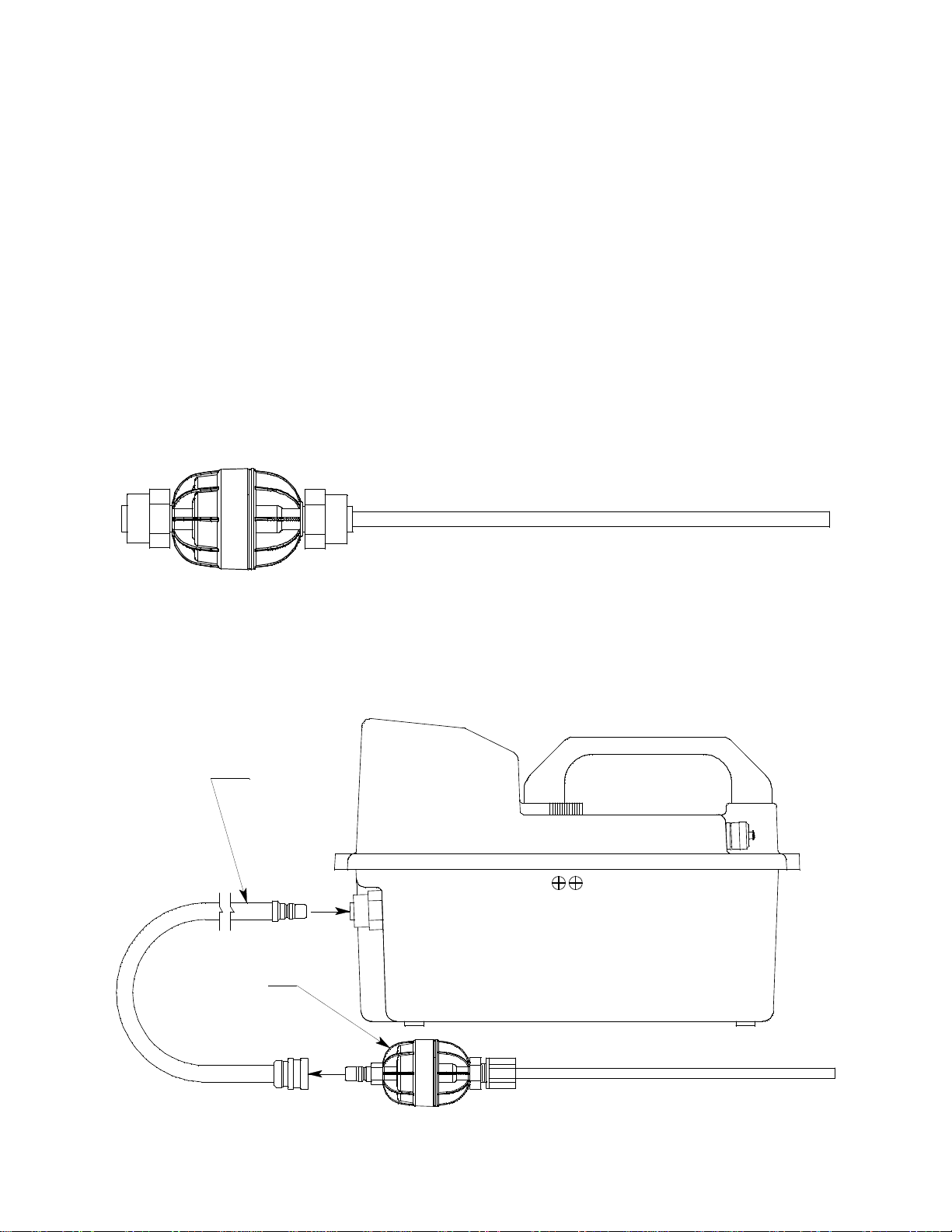
probe has a male quick connect fitting. Normally, the male end of
Standard
Probe
Sample Hose
sample hose is installed in the Eagle inlet fitting and the probe is
installed in the female end of the hose. However, if the sample hose is
not needed for monitoring a particular area, the probe may be
installed directly to the inlet fitting. Sample hose lengths ar e available
from 5 feet (standard length) to 125 feet (see “Appendix A: Parts List”
on page 53).
CAUTION:Sample hose lengths of more than 125 feet are not recomme nded
for the Eagle because of flow rate reduction and increased
response time. Consult RKI Instruments, Inc. for hose lengths
longer than 125 feet.
A super toxic probe is included with instruments that r equir e it. It has
a plastic fitting and is connected to the inle t of th e Eagle with a tubing
stub. See “Appendix C: Non-Standard Toxic Gas Sensors” on page 57
for more information about the super toxic probe and where to use it.
The standard probe includes a replaceable particle filter and
hydrophobic filter disk that prevent particulates and water from
entering the Eagle’s flow system. See “Replacing the Probe’s Particle
Filter and Hydrophobic Filter Disk” on page 48 for instructions to
replace the particle filter and hydrophobic filter disk.
7 • D e s c r i p t i o n Eagle Instruction Manual

Sensors
This section describes the Eagle’s standard sensors. Non-standard
sensors are described in Appendices C, D, E, and J. Y our specific Eagle
model may not include all of the sensors described below. Under
normal conditions, the Eagle’s standar d sensors have an operating life
of approximately two years.
Combustible Gas Sensor
The combustible gas (LEL) sensor is mounted with the flame arrestor
down in the sensor block to allow the sample flow to diffuse into the
sensor. Five pins extend from the top of the sensor. The sensor cable
connects to the pins on one end and terminates in a four-position
connector, which plugs into the COMB socket on the analog print
circuit board (PCB).
The LEL sensor detects combustible gas and vapors in the atmosphere
with a catalytic platinum element. The reaction of gas with oxygen on
the catalyst causes a change in the resistance of the element, which is
converted by the Eagle into a reading of combustible gas
concentration.
Oxygen Sensor
The oxygen (O2) sensor is mou nte d face down in the sensor block to
allow the sample flow to diffuse into the sensor. A multi-pin plug
connects the O
The O
sensor is an electr o chemical cell, which reacts to the oxygen in
2
sensor to the CN2 socket on the analog PCB.
2
the atmosphere and produces a voltage proportional to the oxygen
concentration. This voltage is converted by the Eagle into a reading of
oxygen concentration.
Standard Toxic Sensors (CO and H2S)
The CO and H2S sensors are physically very similar. They have
cylindrical bodies and are mounted face down in the sensor block. A
three-position connector from each sensor plugs into EC1 or EC2
socket on the analog PCB. The sensor connected to the EC1 socket
displays as channel 3; the sensor co nnected to the EC2 socket displays
as channel 4.
The toxics sensors are electrochemical cells, which react to the target
gas in the atmosphere, producing a current proportional to the
concentration of gas. The current is converted by the Eagle into a
reading of target gas concentration.
Eagle Instruction Manual Description • 8

Circuit Boards
The Eagle circuit boards analyze, record, control, store, and display
the information collected.
The analog PCB is mounted perpendicular to the base of the
instrument case. It is located in the same half of the case as the sensors
and sample-drawing system. The sensor leads connect to the analog
PCB.
The main PCB is mounted in the top half of the case. It includes the
methane elimination and CAL/SETUP switches.
CAUTION:The circuit boards should be serviced only by authorized repair
personnel.
Methane Elimination Switch
The methane elimination switch (SW1) is mounted near the top right
corner of the main PCB.
For applications where methane is an interfering gas, you can set the
methane elimination switch to eliminate most response to methane
(see “Appendix B: Methane Elimination” on page 55). An external
methane elimination switch is available as an option.
CAL/SETUP Switch
The CAL/SETUP switch (SW2) is mounted near the middle left edge
of the main PCB.
This switch controls the Eagle functions available to the user by
disabling the SHIF T/▼ button. Without the use of this button, the user
is unable to enter Calibration or Setup mode. (Display mode is
available with either switch setting.) See “Setting User Access” on
page 14 to change the switch setting.
9 • D e s c r i p t i o n Eagle Instruction Manual

Operation
E
S
UDT
N
I
YE
S
A
A
A
:
L
R
S
I
D
OG
R
M
E
?
O
P
:
5
L
AY
BA
T
TERY
MIN
.4.5V
BA
T
TERY
60V.
NO
W
The Eagle has four operating modes: normal operating mode, display
mode, setup mode, and calibration mode. This section describes the
Eagle in normal operating mode. It includes pr ocedures to start up the
Eagle, set various detection options for the combustible gas channel,
and shut down the Eagle.
NOTE: The screens illustrated in this section are intended as
Starting Up the Eagle
1. Connect the sample hose to the Eagle’s quick connect inlet fitting.
2. Connect the hydrophobic filter and probe tip to the sample hose’s
quick connect fitting.
3. Press and briefly hold down the POWER/ENTER button. If the
Lunch Break feature is on (see page 34), the Resume Datalog
screen displays. (If the Lunch Break feature is off, the Battery
Voltage screen displays.)
examples only. The screens displayed by your Eagle model
may be slightly different.
Eagle Instruction Manual Operation • 10
•Press the AIR/▲ button to continue accumulating time-
• Press the DISP/ADJ button to restart these measuremen ts. The
If you do not press the AIR/▲ or DISP/ADJ button within 5
seconds, the Eagle automatically resumes datalog readings and
displays the Battery Voltage screen.
weighted average (TWA) and PEAK readings from the last
time the Eagle was used. (The short-term exposure limit [STEL]
reading is reset each time the Eagle is turned on.) The Battery
Voltage screen displays.
Battery Voltage screen displays

The Battery Voltage screen displays the minimum usable and
PA
17 1
4
:
R
998
130
S
GN
S
S
E
I
S
C
O
DIA O
EL
F
0
NDS
T
O
G
O
ST
A
ND BY
CH
4
><O Y
C>O
H
2
S
<X
>
<<
>
1
CH
4
OY
C
O
H
2
S
X
2
0.9
0
0
0.0
L
V
P
PPPMM
EOLL%
%
actual battery voltage (for example, 6.0V). If the battery voltage is
too low, the Eagle will not continue.
NOTE: The following screen only displays if the data logging option
is installed. If the data logging option is not installed, the Self
Diagnosis screen displays after the Battery Voltage screen.
This message displays the da te and time as set in Setup mode. The
data logging option uses this information to record the time and
date of sample and alarm events.
The following two screens display while the Eagle ch ecks itsel f for
proper operation. The Eagle alerts you if a malfunction occurs.
When the Eagle successfully completes its self check, the OK
message displays in place of the ST AND BY message, then the
normal operating screen displays. The normal screen displays
fresh-air concentrations for all gases. The Eagle sounds a double
tone to indicate it is in normal operation.
CAUTION:Do not use gas from a cigarette lighter to test response to
11 • O p e r a t i o n Eagle Instruction Manual
combustibles. Exposing the combustible gas sensor to
uncontrolled high concentrations of gas will reduce response
and sensor life.

4. Verify that the Eagle is operating correctly. Use the RKI Check Kit
to easily verify correct operation of the Eagle.
WARNING: If the Eagle does not respond to verification, take it to a
known “fresh-air” environment, then perform the
demand zero procedure described in “Preparing for
Calibration” on page 42. Repeat step 4 before using the
Eagle in a potentially hazardous location.
Normal Operation
The Eagle continuously monitors the sampled atmosphere and
displays the gas concentrations present for its target gases. In a lowlight environment, press any button to turn on the display backlight.
(See “Updating the Back Light Setting” on page 37 to program
backlight duration.) If the Confirmation Beep option is turned on, the
Eagle beeps once every 15 minutes to verify that it’s on the job.
To use the probe, insert it into the monitoring area and wait a few
seconds for response.
NOTE: Response time increases with the length of the sample hose.
Very long sample hoses may require several seconds to show
response at the Eagle.
Monitoring Combustible Gas in the PPM Range
1. Start the Eagle in the LEL range as described in “Starting Up the
Eagle” on page 10.
2. Allow the combustibles sensor to stabilize (3 to 5 minutes). This
stabilization period is required for the PPM range only.
3. Press the LEL/PPM button. The Eagle displays PPM in place of
LEL% for combustible gas, and the gas reading displays in parts
per million.
4. If the PPM reading is not zero, take the Eagle to a fresh air
environment, then perform the demand zero procedure as
described in “Preparing for Calibration” on page 42.
NOTE: For the data logging option, combustible gas readings are
logged in %LEL regardless of the LEL/PPM setting.
Monitoring Combustible Gases Other than Methane
If the combustible sensor is calibrated to methane (CH4), use Table 4
to determine the response of other combustible gases. This table is
Eagle Instruction Manual Operation • 12

based on Eagles in full response mode (methane elimination switch
set to CH4) calibrated to methane. Multiply the display reading by the
factor in the appropriate column in the table. For example, if you are
detecting hexane and the display reads 10% LEL, the actual hexane
reading is 10% x 2.14 = 21% LEL hexane.
W ARNI NG: The Eagle’s alarms ar e initiated by the DISPLAY reading
not the FACTORED reading. If you are monitoring for
hexane as in the example above and the low alarm is set
for 10% LEL, the Eagle will initiate a low alarm at 21%
LEL hexane (display reading of 10% LEL).
To determine the concentration of other combustible gases with the
Eagle in methane elimination mode, see Table 7 on page 56.
Table 4: Full Response Mode Conversion Factors (Methane Calibration)
Target Gas LEL Factor PPM Factor Target Gas LEL Factor PPM Factor
Acetone 1.89 1.14 Isobutane 1.79 0.64
Benzene 2.85 .48 Isopropanol 2.19 .43
Butyl Acrylate
Butyl Acetate 4.34 1.49 Methanol 1.72 .91
2-Butyl Alcohol 4.49 1.54 Methyl Acetate 1.68 .54
1-Butyl Alcohol 6.28 .91 Methyl Acrylate 1.92 .54
Cyclohexane 2.77 .57 Methyl Ethyl
Cumene 5.89 .43 Methyl Isobutyl
Ethylene
Dichloride
Ethyl Alcohol 2.04 .55 Nonane 4.28 0.68
Ethyl Chloride 1.72 .27 Pentane 1.92 .58
Ethyl Acrylate 3.57 1.14 Propane 1.59 .67
Hexane 2.14 0.47 Styrene 4.09 .51
**
5.55 .38 Mixed Xylenes 2.94 .48
.57 Methane 1.00 1.00
2.94 .88
Keytone
2.94 .47
Keytone
Hydrogen 1.10 .88 Toluene 2.00 .65
Vinyl Acetate
Monomer
3.55 .89
** Vapor pressure too low for significant LEL reading.
13 • O p e r a t i o n Eagle Instruction Manual

Setting User Access
The CAL/SETUP switch controls the Eagle functions available to the
user. The switch setting does not affect the Eagle’s ability to display
gas readings and indicate gas and malfunction alarms.
1. Turn off the Eagle.
2. Unscrew the two large screws on the top of the case.
3. Turn over the top half of the case, and locate the CAL/SETUP
switch (SW2) near the middle along one edge of the main
processor board.
CAUTION:The Methane Elimination switch (SW1) is on the opposite edge
of the board near the front end. DO NOT confuse these two
switches.
4. Place the CAL/SETUP switch in the appropriate position.
• To give the Eagle access to all modes, place the switch in the
ON position.
• To limit the Eagle to normal operating and display modes,
place the switch in the OFF position. (The Eagle prevents
access to the setup and calibration modes by disabling the
SHIFT/▼ button.)
5. Place the top of the case in its original position, then secure it with
the large screws you loosened in step 2.
6. Turn on the Eagle.
NOTE: Make sure the Eagle’s calibration is current and the setup
options are appropriate and safe for the operating
environment before placing the CAL/SETUP switch in the
OFF position.
Turning Off the Eagle
To turn off the Eagle, press and hold down the POWER/ENTER
button until GOOD-BYE displays, then release the button. (You must
wait for GOOD-BYE to disappear before you can turn on the Eagle
again.)
Eagle Instruction Manual Operation • 14

Alarms
CH
4
OY
C
O
H
2
S
X
2
0.9
0
0
0.0
L
V
P
PPPMM
EOLL%
%
ALM
11
CH
4
OY
C
O
H
2
S
X
2
0.9
0
0
0.0
L
V
P
PPPMM
EOLL%
%
A
LM
25
Alarm Indications
This section describes the Eagle’s audible and visual alarm indications
for gas, over range, low flow, low battery, and sensor failure alarms.
This section also describes how to reset gas alarms.
The default alarm settings are listed in Table 2, “Standard Sensor
Specifications” on page 4. The alarm settings are user-adjustable as
described in “Updating the Alarm Point Settings” on page 33.
NOTE: The screens illustrated in this section are intended as
First Gas Alarm
If a channel’s gas reading exceeds the first alarm setting (falls below
for the oxygen channel):
examples only. The screens displayed by your Eagle model
may be slightly different.
• ALM1 displays in the alarm field for that channel.
• The channel’s display line flashes.
• The buzzer sounds a pulsed tone.
• The alarm lights flash.
Second Gas Alarm
If a channel’s gas reading exceeds the second alarm setting:
• ALM2 displays in the alarm field for that channel.
• The channel’s display line flashes.
• The buzzer sounds a pulsed tone.
• The alarm lights flash.
15 • A l a r m s Eagle Instruction Manual

STEL Alarm (Toxics Only)
CH
4
OY
C
O
H
2
S
X
2
0.9
0
0
0.5
L
V
P
PPPMM
EOLL%
%
STE
1
L
CH
4
OY
C
O
H
2
S
X
2
0.9
0
0
0.0
L
V
P
PPPMM
EOLL%
%
T
WA
1
CH
4
OY
C
O
H
2
S
X
4
0.0
0
0
0.0
L
V
P
PPPMM
EOLL%
%OVER
If a toxic gas channel’s average gas reading for the past 15 minutes
exceeds the STEL alarm setting:
• STEL displays in the alarm field for that channel.
• The channel’s display line flashes.
• The buzzer sounds a pulsed tone.
• The alarm lights flash.
TWA Alarm (Toxics Only)
If a toxic gas channel’s average gas reading for the past 8 hours
exceeds the TWA alarm setting:
• TWA displays in the alarm field for that channel.
• The channel’s display line flashes.
• The buzzer sounds a pulsed tone.
• The alarm lights flash.
Over Range Alarm
If a channel’s gas reading exceeds that channel’s full-scale setting:
• OVER displays in the alarm field for that channel.
• The channel’s display line flashes.
• The buzzer sounds a pulsed tone.
• The alarm lights flash.
Eagle Instruction Manual Alarms • 16

Low Flow Alarm
F
FLLOW E
L
OW
A
IL
LEV
CH
4
OY
CO
H
2
S
X
2
0.9
0
0
0.0
L
V
P
PPPMM
EOLL%
%
B
A
T
Low Battery
Warning
BA
T
TERY
MIN
.
4.5V
BA
TTE
RY
G
C
H
N
A
E
Low Battery
ALARM
If the Eagle’s sample system becomes restricted or blocked (for
example plugged probe, fouled filter, pinched tubing):
•The message FAIL LOW FLOW LEVEL replaces the normal screen.
• The buzzer sounds a steady tone.
• The alarm lights are on continuously.
• The pump automatically shuts off to prevent damage.
Correct the flow blockage. Press the RESET/SILENCE button to turn
off the alarms and restart the pump. If low flow conditions still exist,
the Eagle will go into alarm again. If the condition cannot be corre cted
immediately, take the Eagle out of service to a non-hazardous area.
Low Battery Alarm
When the battery charge drops near the lower limit, the Eagle
displays the following screen (BAT flashes). For alkaline batteries, you
have approximately 3 hours of use r emaining; for Ni-Cd batteries you
have approximately 15 minutes of use remaining.
When the battery voltage drops to the minimum limit, the following
screen displays, the alarm lights are on continuously, and the buzzer
sounds a steady tone. The Eagle is not operational as a gas monitoring
device when this screen displays.
NOTE: If you are using the data logging accessory and the Eagle goes
into Low Battery ALARM, shut off the Eagle in order to save
the current data logging session.
17 • A l a r m s Eagle Instruction Manual

Sensor Failure Alarm and Emergency Operation
><O
Y
>
<X
>
<<
>
FA
IL
SENSOR
CH
4
OY
C
O
H
2
S
X
0
0
0.0
L
V
P
PPPMM
EOLL%
%xxxxx
The Eagle continuously monitors itself for proper operation. If a
malfunction occurs, the Eagle alerts you with audible and visual
alarms.
If a sensor fails during start-up or normal operation:
• The message F A IL SENSOR displays.
• The failed sensor displays in parenthesis.
• The buzzer sounds a steady tone.
• The alarms lights flash.
If the sensor failed during start-up, the Eagle continues with the normal
start-up sequence after the fail screen displays. When the normal
screen displays, the Eagle replaces the gas reading for the failed
sensor with xxxxx.
If the sensor fails during normal operation and you want to continue
monitoring for the remaining target gases, turn the Eagle off, then follow
the appropriate start-up sequence. When the normal screen displays,
the Eagle replaces the gas reading for the failed sensor with xxxxx.
Eagle Instruction Manual Alarms • 18

Resetting Gas Alarms
You can set the Eagle’s gas alarms for latching or self-resetting alarms
(see “Updating the Alarm Latching Setting” on page 35).
Self-Resetting Alarms
Self-resetting alarms automatically shut off and reset when the gas
reading falls below (or rises above for oxygen) the alarm setting. You
cannot silence or reset self-resetting alarms.
Latching Alarms
You can set latching alarms with or without Alarm Silence (see
“Updating the Alarm Silence Setting” on page 35).
With Alarm Silence On:
When the Eagle goes into gas alarm, press the RESET/SILENCE
button to silence the buzzer . The LEDs continue to flash, and the Eagle
continues to display the current alarm level.
The gas reading must fall below (or rise above for oxygen) the low
alarm (ALM1) setting before you can reset the alarm. Press the
RESET/SILENCE button to reset the alarm. The LEDs turn off and the
Eagle returns to the normal screen.
With Alarm Silence Off:
The gas reading must fall below (or rise above for oxygen) the low
alarm (ALM1) setting before you can reset the alarm. Press the
RESET/SILENCE button to reset the alarm. The LEDs and buzzer
turn off, and the Eagle returns to the normal screen.
NOTE: With Alarm Silence off, you cannot silence the buzzer while
the gas reading is above (below for oxygen) the low alarm
(ALM1) setting.
19 • A l a r m s Eagle Instruction Manual

Display Mode
SE
RD
A
TI
OT
IN
D
U
S
I
*
*********
*
*********
The Eagle has four operating modes: normal operating mode, display
mode, setup mode, and calibration mode. With the Eagle in display
mode, you can:
• set user and station IDs
• display peak readings
• display elapsed time
• display TWA and STEL readings (toxic gases only)
• display battery voltage
• display date and time (data logging option only)
• clear the data log (data logging option only)
• display remaining log time (data logging option only)
To enter display mode, from the normal screen press the DISP/ADJ
button. To scroll from one screen to the next press the DISP/ADJ
button.
NOTE: Each screen displays for 20 seconds. If you do not press the
DISP/ADJ button to scroll to the next screen wit h in 20
seconds, the Eagle automatically returns to the normal
operatin g sc reen.
User and Station ID Screen
This screen displays only if the user ID function is activated (see
“Turning the User ID Function On or Off” on page 36). Each ID
contains 10 characters. Uppercase letters, numbers, asterisks (*), and a
blank space are available characters.
Use this screen to identify the user, the location, or other information.
If your Eagle includes the data logging option, the User and Station ID
provides a way to identify the user and location of exposure. The User
and Station ID are saved to the data logger when you turn off the
Eagle, so you can update the IDs for each data logging session.
Eagle Instruction Manual Display Mode • 20
 Loading...