

Rivera Primo Powerdrive 6 Transmission Shifter Cam User Manual
12450 Whittier Blvd. Whittier Ca. 90602
(562)907-2600 Fax: (562)907-2606
www.riveraprimoinc.com
INSTRUCTIONS
Disassembly
Shifter Cam Assembly
Shifter Forks
WARNING
To protect against accidental start-up of vehicle,
always disconnect the negative battery cable before
working on the motorcycle. Failure to disconnect the
battery cable could result in serious injury or death.
1. Remove battery negative cable (black) from battery
negative (-) terminal.
2. Remove exhaust system.
3. Remove the magnetic drain plug at the bottom right
side of the oil pan and drain the transmission uid.
Remove the ll plug/dipstick.
4. Remove connector from neutral safety switch.
5. Remove the ve socket head cap screws from the
transmission top cover. Remove the top cover from
the transmission case. Do not re-use the
top cover gasket .
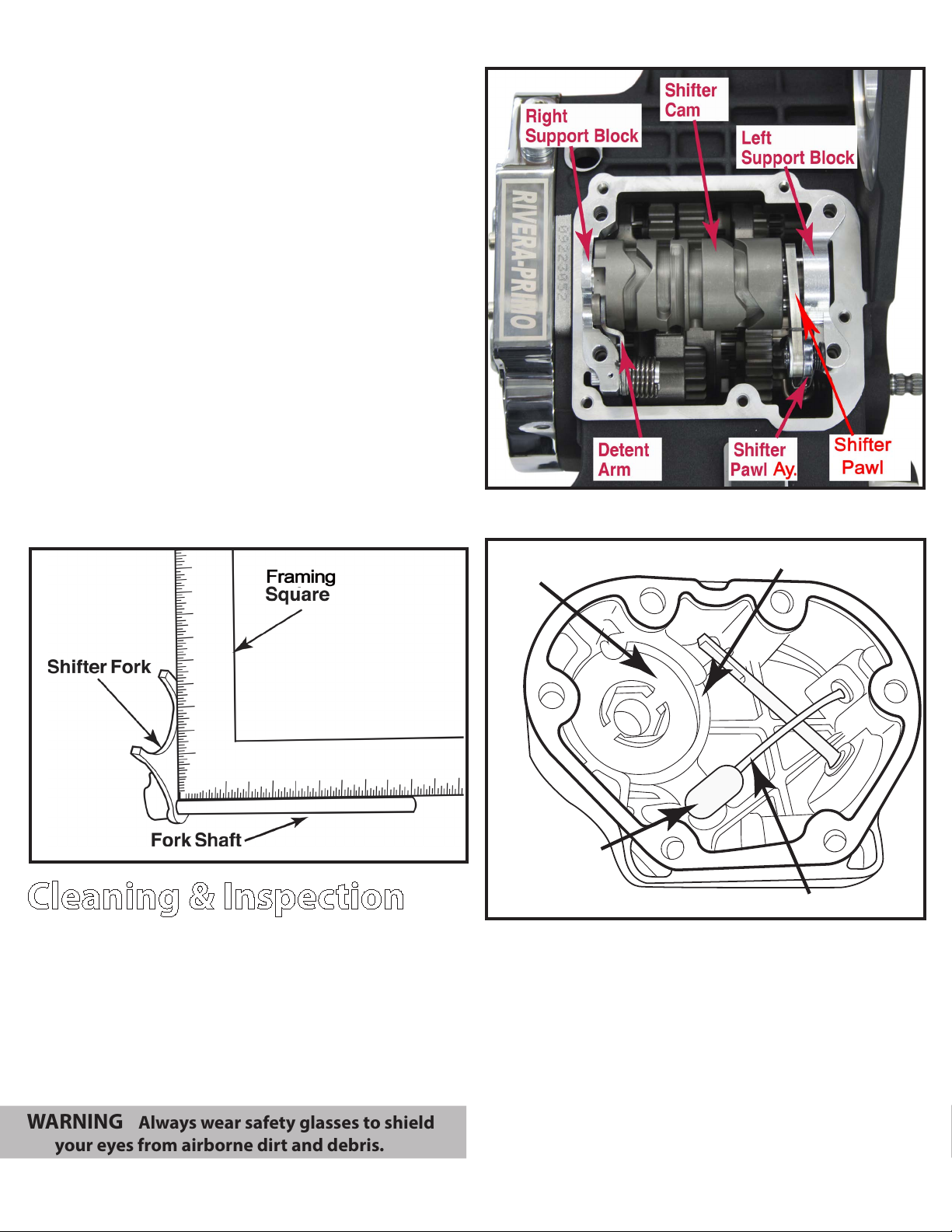
6. Remove the four bolts and washers from the right
and left shifter cam support blocks. Raise the shifter
pawl and lift the shifter cam assembly from the
dowels on the transmission case.
7. If necessary, disassemble the shifter cam
assembly as follows:
a. Lift detent arm and slide right support block
o end of shifter cam. Remove pivot screw to release
detent arm,spring sleeve and spring. Remove
retaining ring (Do not re-use). If the needle bearing
is damaged, remove the bearing from the support
block by pressing it out and replace
with a new bearing.
b. Moving to opposite side, using a snap ring pliers
remove retaining ring from groove at left end of
shifter cam. Slide left support block o end of shifter
cam. DO NOT re-use retaining ring. If the needle
bearing is damaged, remove the bearing from the
support block by pressing it out and replace
with a new bearing.
WARNING
Always wear proper eye protection when removing
retaining rings. Failure to do so may result in eye injury.
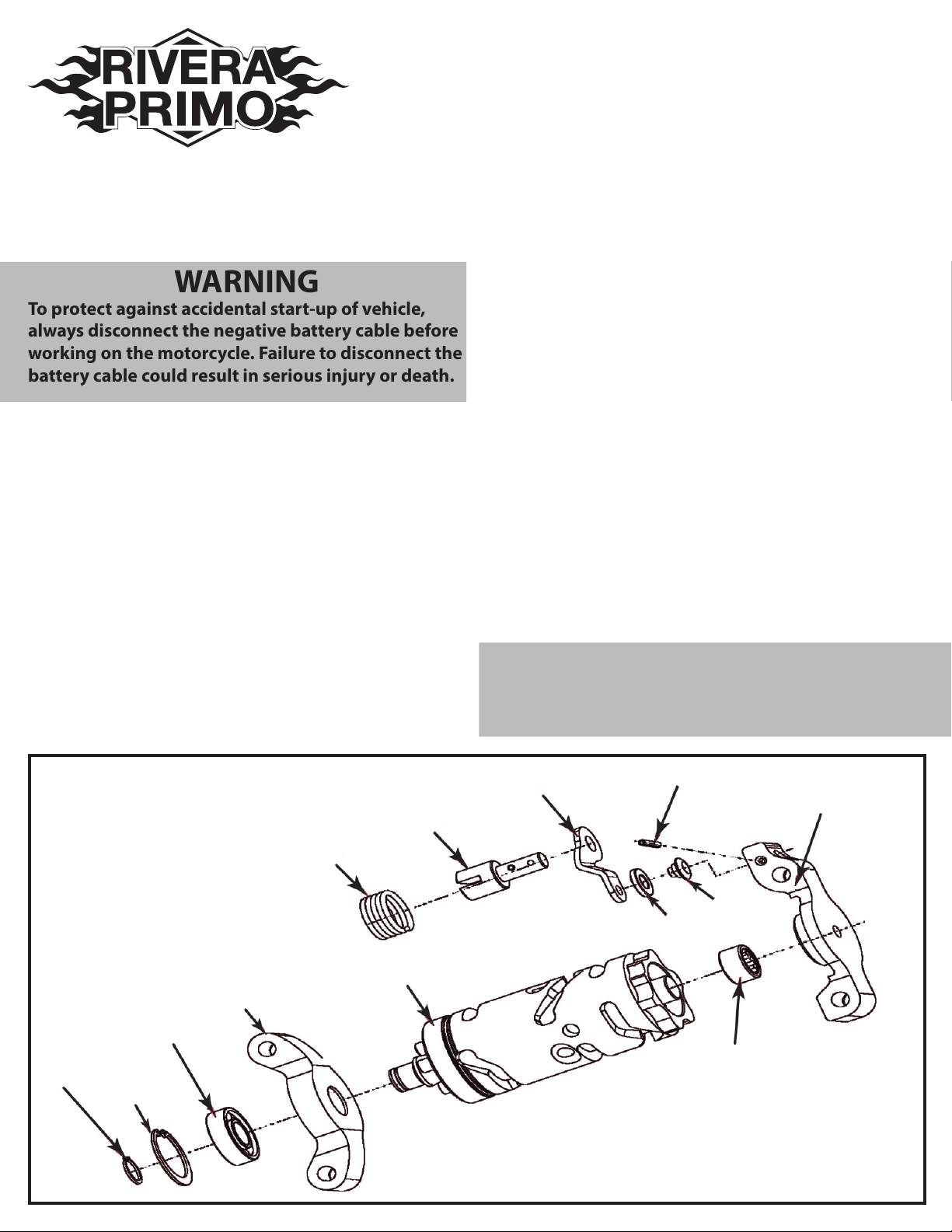
Shifter Cam Assembly
Exploded View
Support Tower (LH)
1217-0641
Cam Bearing
1018-0016
Retaining Ring
1101-0061
Retaining Ring
1101-0062
Coil Spring
1217-0645
Spring Hanger
1217-0640
Cam LSD
1217-0636
Cam Follower Arm
1217-0639
Roll Pin
1217-0647
Roller
1217-0646
Roller Shaft
1217-0644
Bearing
1018-0017
Support Tower (RH) LSD
1217-0642
Fig.1
8. Slide rubber boot o clutch cable adjuster. With a 1/2
inch wrench holding the cable adjuster, loosen jam
nut to get a signicant amount of free
play at hand lever.
9. Remove six socket head screws to remove clutch
release cover from the transmission side door.
DO not re-use the gasket.
10. Remove retaining ring from inner ramp, then lift inner
ramp out of clutch release cover. Turn the inner ramp
over so that ball pockets are facing outboard. Remove
hook of ramp from button on coupling. Remove the
coupling from clutch cable end.
11. Unscrew the cable from the clutch release cover. Remove the clutch cable.
12. Remove the mainshaft fork shaft from the hole on the
right side of the transmission case by sliding outward,
then remove the 1st gear fork shaft by rst removing
the threaded plug, then slide the shifter fork back
and forth until the shouldered head of the fork shaft
protrudes through the hole in the bearing housing.
Remove the shifter forks from the mainshaft and
countershaft grooves. (See Fig. 5 & 6)
Check Shifter Forks for Squareness
Shifter Cam Assembly
Fig.2
Clutch Release Cover Assembly
Fig.3
Cleaning & Inspection
1. Clean all parts with solvent prior to installing any
bearings. Blow dry with low pressure air.
2. Inspect roller bearings make sure that bearings rotate freely without binding.
3. Inspect the shifter cam for cracks or wear. Inspect the
ends for grooves or pitting. Always install new roller
bearings whenever the shifter cam is replaced.
WARNING: Always wear safety glasses to shield
your eyes from airborne dirt and debris.
4. Inspect the shifter fork shaft and replace
if bent or damaged.
Retaining Ring
Inner Ramp
Coupling
Fig.4
5. Using a small framer’s square, verify that the shift-
er fork shafts are square. If a fork does not rest at
against the square, it is bent and must be replaced.
(See Fig. 3)
6. Inspect the shifter forks for wear. With a micrometer
or dial caliper, measure the width of the fork where
they contact the gear fork grooves. Replace any fork
that measures less than 0.170” (4.32 mm)
7. Inspect the neutral safety switch. Depress plunger
and observe the action. Plunger should pop back
without binding. The switch is not repairable and
must be replaced if inoperable.
Clutch Cable
 Loading...