


HOME OF PRIMO® BELT DRIVES
QUALITY & PERFORMANCE SINCE 1973
INSTALLATION INSTRUCTIONS FOR
Brute IVTM
Belt Drives
3” Wide 8mm Belt
Fits 1970-2006
Big Twins
(Except Late 1978-86 w/Rotary Top 4-Speed Trans)
**To prevent serious injury, all open belt drives must be run with a full coverage Belt Guard !
BRUTE IV TM SHOWN WITH STANDARD POLISHED ALUMINUM BELT GUARD (PP-419-P-AY), SUPPLIED IN KIT (NON RUBBER-MOUNT MODELS)
BRUTE IV TMKIT SHOWN WITH OPTIONAL FLAMED BELT GUARD
# 2014-0010
It’s common knowledge that a belt drive primary can provide advantages and service that a chain cannot, especially considering the new technology present in every belt. For dependable, high performance, long-life service nothing beats a modern Primo® Belt Drives primary-drive belt-kit! Primo’s long-time tradition of “Quality & Performance” has made our belt drives the most popular in the world. That same quality & performance is now available in the Brute IVTM 3” wide open electric-start primary belt-drive for most Big-Twin motorcycles. The Brute IVTM is ideal for streetperformance, competition, and show-bike applications. It looks as good as it works. Carefully read and follow these instructions for a quick, convenient installation. If you have any questions regarding this installation call (562) 907-2600 and a PRIMO® BELT DRIVES technician will be happy to assist you!
Use of the word Harley-Davidson, various motorcycle model names & designations & OEM part numbers are for end-user reference or application information only. No affiliation between Rivera Primo Inc. & The Harley-Davidson Motor Company exists or is implied by the use of said information. Rivera Engineering, ProClutch, Primo, and Primo Belt Drives are registered trademarks of Rivera Primo Inc. Unauthorized use is prohibited by law. law.
IMPORTANT SAFETY NOTE....
When performing any motorcycle work such as installing a belt drive it should be securely fastened in an upright position with easy access to the primary drive. If you are working with a lift, fasten the motorcycle securely to prevent it from falling.
Always remove the battery to prevent accidental start-up.
www.riveraprimo.com |
2108-0005 |
1 |

STEP 1:
Begin by disconnecting battery cables. Removing all the OEM primary-drive components including the inner primary cover, AND THE FACTORY INNER-BEARING RACE ON THE TRANSMISSION MAIN SHAFT! Check the motor shaft & transmission main shaft for leaky seals. Check & thoroughly clean the motor drive shaft & trans main shaft. Check & tighten the shift-lever as needed at this time!
If you wish to change the final drive ratio, now is the time to install a rear belt drive transmission pulley (tighten nut perprocedure outlined in HD facto-
ry service manual). Primo’s billet aluminum rear drive pulley is available with 29, 30, 32, or 34 teeth & weighs 3 pounds less than the OEM unit.
STEP 2:
Install the starter coupler onto the end of the starter motor as shown. This component must be installed prior to the installation of the bearing support.
1
2
1986-1988 Softail / FXR applications: |
2A |
Adequate clearance for the coupler must be made. Remove |
|
approximately .150” of material in the area indicated by the X |
|
(use the 7 o’clock position as your guide). |
|
A 1990 or later starter motor is required. The Primo Belt |
|
Drives adapter plate (PP-407H) is mounted between the |
|
starter motor and the transmission starter boss as pictured. |
|
1970-78 Shovelhead applications (ratchet top only). |
|
A 1990 & later starter motor is required for Shovelheads. A |
|
Primo Belt Drives adapter plate (PP-306) is mounted between |
|
the starter motor & the transmission starter similar to the Softail |
|
adapter. |
|
STEP 3: |
3 |
|
Install the bearing support (rear motor plate section PP-304, PP-404, PP-504, or PP-604). Carefully align the bolt-holes and install the bearing support over the starter extender. Only hand tighten the bolts at this time. Attach the 1990 or later starter motor to the rear of the bearing support (1986 Softails require an adapter PP-407-I) (1970-78 Shovelhead with ratchet top requires the starter adapter PP-306).
2
STEPS 3A & 3B: |
|
|
|
|
|
|
|
|
|
|
|
|
|
|
|
|
||
|
|
|
|
|
|
3A |
|
|
|
|
3B |
|
|
|||||
Primo Belt Drives PP-502 Motor Plate assembly (rear section) for |
|
|
|
|
|
|
|
|||||||||||
Dyna Glide is notched for swing-arm pivot-boss clearance (photo 3A). |
|
|
|
|
|
|
|
|
|
|
|
|
||||||
|
|
|
|
|
|
|
|
|
|
|
|
|||||||
|
|
|
|
|
|
|
|
|
|
|
|
|||||||
Approximately .125” of material must be removed from the end of the |
|
|
|
|
|
|
|
|
|
|
|
|
||||||
nut & swing arm pivot bolt assembly (photo 3B) to allow clearance for |
|
|
|
|
|
|
|
|
|
|
|
|
||||||
the Brute IV starter ring-gear before installing the clutch basket. |
|
|
|
|
|
|
|
|
|
|
|
|
||||||
Remove enough material from the end of the nut & bolt to allow the |
|
|
|
|
|
|
|
|
|
|
|
|
||||||
starter ring gear & clutch basket assembly to be installed & rotated with |
|
|
|
|
|
|
|
|
|
|
|
|
||||||
approximately .100” clearance between the ring gear & the nut-bolt. |
|
|
|
|
|
|
|
|
|
|
|
|
||||||
STEP 4: |
|
|
|
|
|
|
|
|
|
|
|
|
|
|
|
|
||
|
|
|
|
|
|
|
|
|
|
|
|
|
|
|
|
|||
|
|
|
|
|
|
|
|
|
|
|
|
|
|
|
|
|||
|
|
|
|
|
|
|
|
|
|
|
|
|
|
|
|
|||
Install the Motor Plate (front section PP-303, PP-403, PP-503, |
|
|
4 |
|
|
|
|
|
|
|
|
|
|
|
|
|
||
or PP-603), start the four front section bolts, but only hand tight- |
|
|
|
|
|
|
|
|
|
|
|
|
|
|
||||
en at this time! |
|
|
|
|
|
|
|
|
|
|
|
|
|
|
|
|
|
|
|
|
|
|
|
|
|
|
|
|
|
|
|
|
|
|
|
||
|
|
|
|
|
|
|
|
|
|
|
|
|
|
|
|
|
||
Install the 4 center bolts that attach the front section of the |
|
|
|
|
|
|
|
|
|
|
|
|
|
|
|
|
||
Motor Plate Assembly to the rear section. TIGHTEN THE |
|
|
|
|
|
|
|
|
|
|
|
|
|
|
|
|
||
MOTOR PLATE BOLTS, THE BEARING SUPPORT BOLTS |
|
|
|
|
|
|
|
|
|
|
|
|
|
|
|
|
||
AND THE CENTER BOLTS TO 29 FOOT POUNDS OF |
|
|
|
|
|
|
|
|
|
|
|
|
|
|
|
|
||
TORQUE AT THIS TIME, WHILE ENSURING THAT THE |
|
|
|
|
|
|
|
|
|
|
|
|
|
|
|
|
||
PLATES ARE PROPERLY SEATED AND ALIGNED. If you |
|
|
|
|
|
|
|
|
|
|
|
|
|
|
|
|
||
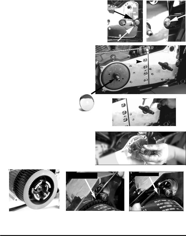
have a PP-400 (show chromed alternator cover) install it now! |
|
|
|
|
|
|
|
|
|
|
|
|
|
|
|
|
||
|
PP-400 |
|
|
|
|
|
|
|
|
|
|
|
|
|
|
|
|
|
|
|
|
|
|
|
5 |
|
|
|
|
|
|
|
|
||||
STEP 5: |
|
|
|
|
|
|
|
|
|
|
|
|
|
|
|
|||
|
|
|
|
|
|
|
|
|
|
|
|
|
|
|
|
|||
Apply a liberal amount of bearing grease to the transmission main-shaft |
|
|
|
|
|
|
|
|
|
|
|
|
||||||
splines to act as a corrosion inhibitor. The grease also protects the |
|
|
|
|
|
|
|
|
|
|
|
|
||||||
splines by absorbing shock-loads & preventing rust. |
|
|
|
|
|
|
|
|
|
|
|
|
|
|
|
|
||
|
|
|
|
|
|
|
|
|
|
|
|
|
|
|
|
|
|
|
STEP 6: |
|
|
|
|
|
|
|
|||
|
|
|
|
6 |
|
|||||
Install the starter jack shaft mechanism (extender, spring, pin- |
|
|
||||||||
ion gear, thrust washer, lock washer, and bolt). Make sure the |
|
|
||||||||
|
|
|
|
|||||||
lock washer is correctly oriented. Use 1-2 drops of blue |
|
|
|
|
||||||
threadlock & snug the bolt. Bend the locking-tab over to keep |
|
|
|
|
||||||
the bolt from vibrating loose. |
|
|
|
|
|
|
|
|||
|
See page 7 for starter mechanism diagram! |
|
|
|
|
|||||
|
|
|
|
|
|
|
|
|
|
|
|
|
|
|
|
|
|
|
|
|
|
|
|
7 |
|
|
|
|
|
|
|
|
|
|
|
|
|
|
Air gap between ring gear |
|
|
|
|
|
|
|
|
|
|
and pinion gear |
|
|
|
|
|
|
|
|
|
|
|
|
|
|
|
|
|
|
|
|
|
|
|
|
|
|
STEP 7:
Measuring the air gap
Install the rear pulley (clutch basket) and hand tighten the clutch hub nut making sure it is snug. Note that this nut is left-hand thread. At this time it is important to check the air gap between the back side of the starter ring
gear and the pinion gear. Recommended gap should be .075” to .125”. Use an 1/8” Allen wrench to measure the gap. Just slip the short end of the wrench between the ring gear & the pinion gear. If it fits, great. If there is too much gap, the jackshaft assembly should be shimmed to reduce the gap to the spec above (order #1185-0500 shim kit).
3
 Loading...