

Page 1

1
I
I
NST
NST
ALLA
ALLA
TION
TION
Instructions
for SHOVELHEAD & IRONHEAD XL
42mm Mikuni Carburetor & Manifold Kit
12450 Whittier Blvd., Whittier, CA 90602 Tel:(562) 907-2600 Fax: (562) 907-2606
www.riveraprimoinc.com
REQUIRES 1990-95 OEM BIG-TWIN STYLE THROTTLE CABLES.
THROTTLE CABLE LENGTH IS DEPENDENT UPON HANDLEBAR HEIGHT.
1108-0010 / Revised 3-08
For all Shovelhead applications 1970-1984 and all Ironhead Sportster models 1971-1985.
Pre-1971 model XL cannot be fitted due to the fact that 1958 XLCH used a magneto or distributor located directly
below the carburetor. 1954-to-1970 KH, XL, XLH, XLH-70, and XLCH have a stand-up a distributor located directly
below the carburetor.
* NOT LEGAL FOR SALE OR USE IN CALIFORNIA OR ON ANY POLLUTION CONTROLLED MOTOR VEHICLES.
HOME OF PRIMO®BELT DRIVES
QUALITY & PERFORMANCE SINCE 1973
Page 2
APPLICATIONS
This installation instruction set applies to the Rivera-MIkuni HSR42
carburetor kits for 1970-1984 Harley-Davidson "Shovelhead" BigTwin & 1971-1985 Iron Head XL motorcycles. Intake manifold, all necessary hardware & a high performance Mikuni / K&N air filter are
included. 1990-95 style throttle cable cables are required.
DISASSEMBLY
1) Disconnect the negative (minus) battery terminal.
2) Turn the gas petcock to the off position.
3) Removes the gas tank(s) from the motorcycle or elevate
the rear of the gas tanks for better access to the
cylinder/intake manifold area.
4) Remove the air cleaner assembly including backing
plate.
5) Disconnect the choke cable from the motorcycle.
6) Disconnect the vacuum hoses and gas supply hose from
the carburetor.
7) Remove the carburetor from the motorcycle.
8) Remove existing throttle cables. 1990-1995 OEM style
throttle cables are required.for this installation.
INSTALLATION
1. INTAKE MANIFOLD
A) Attach the enclosed rubber flange to the Rivera intake
manifold with 2 each 5/16" X ¾" bolts & flat washers.
B) Attach the Mikuni intake manifold assembly to the heads
in place of the stock intake manifold. Do not torque the
clamps tight at this time; later, installation of the air cleaner
assembly will bring the manifold into proper alignment.
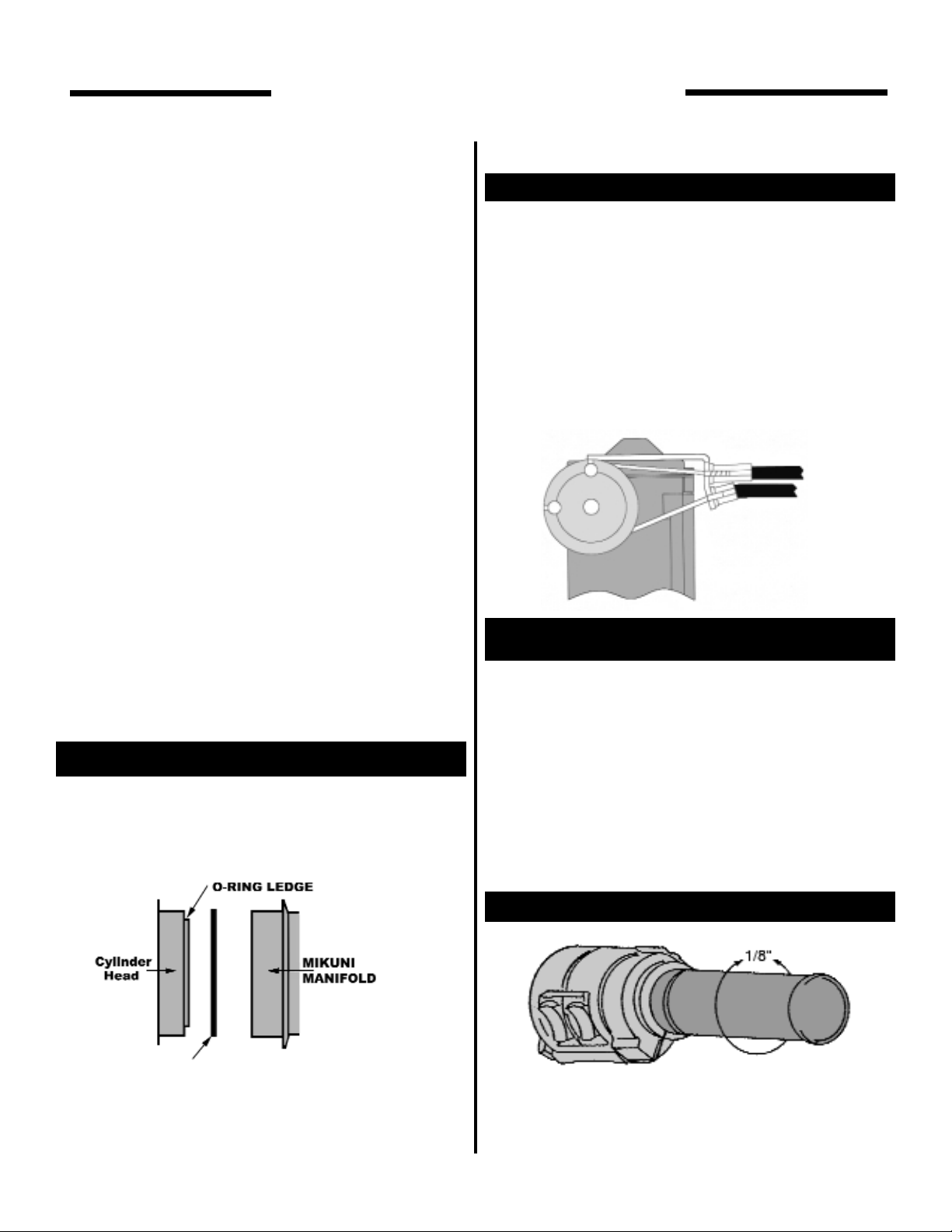
Please note
Special adapter rings are included to be used on the
intake manifold as illustrated. These rings enable the
use of "rubber-band" style manifold seals and large
diameter clamps. See the following illustration.
2. CARBURETOR INSTALLATION
A) Insert the carburetor spigot into the rubber flange, and
tighten the clamp securely.
3. THROTTLE CABLES
CAUTION
Two throttle cables are REQUIRED for the HSR carb. If
you do not have a dual cable pull-open, pull-closed
throttle cable assembly, you must obtain a dual cable
throttle assembly. Lubricate throttle cables prior to
connecting to carburetor..........
USE 1990-95 OEM throttle cables
A) Route the cables to the carburetor along the right side of
the frame (just like stock). Next, route the cable below the
top motor mount to the carb
B) Connect the cables to the carburetor bracket as shown.
First the pull-to-close cable (idle cable) and then the pull-toopen cable.
4. THROTTLE CABLE ADJUSTMENT
A) Rotate the throttle grip to the full open position, look into
the throttle bore and see if the throttle valve (slide) opens
completely. If the throttle valve does not open completely
unscrew the adjuster on the opening cable until it does. This
adjustment should be made carefully to assure maximum
carburetor performance. After adjustment tighten the
adjuster jam nut.
B) After adjusting the open cable, adjust throttle freeplay
with the closing (idle) cable to approximately 1/8" an indicated in the following illustration.
note
It is very important to adjust the cables in the preceding
described manner to ensure that the idle cable operates
correctly for safety. It must close the throttle completely
2
PLEASE NOTE
USE CAUTION
PLEASE NOTE
SAFETY WARNING
pull open cable
pull close cable
SHOVELHEAD/IRONHEAD XL
Installation Instructions
Page 3

Check and make sure that the throttle cables are routed properly by rechecking the throttle play as the handlebars are turned from side-to-side; the amount play
should remain consistent.
C) After the throttle cables have been adjusted, make sure
that all the lock nuts are securely tightened.
5. AIR CLEANER
A) The air filter bracket is attached to the crankcase with 1
long bolt, and a bracket-spacer. Removed the crankcase
nut located between the tappet blocks & replace it with the
enclosed bracket spacer; tighten the spacer securely.
B) Remove the stud protectors from the K&N filter and
place the two backing plates on the studs. Now slip the the
filter onto the carburetor.
C) Attach the 2 long brackets to the air filter studs with the
enclosed nuts & flat washers, and to the bracket spacer with
the enclosed bolt using the lock washers, and flat washers.
When the carburetor and air cleaner are properly aligned,
securely tighten all of the mounting hardware including the
intake manifold clamps.
In some cases it may be necessary to bend the
brackets slightly to arrive at the correct fit.
D) Use the enclosed hose clamps to secure the fuel hose to
the petcock, and the HSR carburetor. The screw clamp
goes on the petcock end and the spring clamp attaches to
the carburetor end.
E) Attach the chrome air filter cover with the enclosed
socket head screw.
7. CHOKE CABLE INSTALLATION
A) Attach the Mikuni choke cable bracket to the original
choke cable bracket on the air cleaner stud with the enclose
hardware as illustrated.
B) Route choke cable to it's mounting bracket and tighten
the jam nut securely. After the cable is securely fastened,
adjust choke cable to have 1mm (.040") of free play with the
adjuster located under the rubber cover at the carb.
8. OVERFLOW HOSE
A) Route the carburetor overflow hose between the push
rod tubes and the rear cylinder, then downward towards the
frame.
9. STARTING
Reconnect the battery and reassemble the remainder of
the motorcycle. Turn on the gas, and start the motorcycles
as you would normally. After the motor has warmed up,
adjust the idle to the desired RPM.
CAUTION
To properly maintain the HSR42's superior high
performance capabilities, it is recommended
that the air cleaner be inspected at 5,000 mile
intervals. Clean/replace the filter as needed.
3
USE CAUTION
use the new case bolt included in the kit!
USE CAUTION
SHOVELHEAD/IRON HEAD XL
Installation Instructions
spacer
Page 4

4
Parts list for HSR42mm Mikuni
Part # Description Qty.
990-662-002 Choke Cable Assembly 1
HSR42/012 Air Cleaner 1
HSR42/018-42 Rubber Flange 1
HSR42/021-250 Cover A/C (CHR) 1
HSR42/027 Bracket, Air Filter 2
1043-0004 Carb Assembly 1
N100.604-155 Main Jet#155 1
N100.604-165 Main Jet#165 1
RE-0069 Bracket spacer 1
RE-AD-8183 Manifold Adapter 2
RIV-002 Bolt socket head
for rubber flange 2
RIV-0029 Lock Washer, 5/16" 4
RIV-003 Center Case Bolt 1
RIV-0045 Flat Washer, 5/16" 6
RIV-005 Choke Bracket 1
RIV-0061 Manifold 1
RIV-007 5/16" AN Flat Washer 2
RIV-017 Fuel Line 2 feet 1
RIV-0070 Cable Bracket 1
RIV-020 Clamp, Hose 2
RIV-201 Nut, 5/16"18 2
RIV-202 Bolt, 5/16"18 x 3/4" 1
RS36/47 Plate, Back 2
RS36/54 Screw, Cover 1
TMX/0032 Clamp, Hose 1
SHOVELHEAD/IRON HEAD XL
Installation Instructions
Page 5

5
MIKUNI HSR42 CARBURETOR
HSR42'S TUNING CIRCUITS & HOW THEY
WORK:
IDLE CIRCUIT (PILOT SYSTEM)
The idle circuit supplies fuel at idle speeds & has a big influence on fuel flow up to 1/4 throttle. There are three tunable
parts in the idle circuit:
1). PILOT JET-controls maximum fuel flow thru the idle circuit.
2). PILOT AIR JET-controls the maximum amount of fuel that
will flow thru the pilot jet by allowing a higher (smaller air jet) or
lower (larger air jet) vacuum signal at the pilot jet.
3). PILOT SCREW-controls how much fuel is allowed to enter
the carburetor venturi.
The pilot screw is used to control idle mixture. Turn the screw
out to richen the idle mixture. Turn it in to lean the mixture. The
engine should have a smooth, steady idle with the screw
between 1/4 and + 3-1/2 turns out from fully bottomed (gently!).
If the engine requires more than three turns out, the pilot or
pilot air jet may be too lean. If it requires less than 1/4 turn, it
may be too rich.
As the throttle is opened the pilot screw's position becomes
less important than the size of the pilot & pilot air jets. A larger
pilot jet richens the mixture from just off-idle to 1/4 throttle. A
smaller one leans it. A change in pilot air jet has the reverse
effect. A larger pilot air jet leans the mixture and a smaller one
richens it. The pilot jet & pilot air jet have slightly different
effects on mixture strengths. These effects are discussed in the
"General Tuning Procedure”.
The idle circuit is adjusted by changing either the pilot or the
pilot air jets. A one-size larger pilot jet will have nearly the same
effect as a one-size smaller pilot air jet. It is generally easier to
change the air jet since it is more accessible.
After changing either jet, it will be necessary to re-adjust the
pilot screw for best idle.
MAIN SYSTEM
The main system delivers fuel from 1/16 to full throttle. The idle
circuit delivers the majority of the fuel near 1/16 throttle. The
main system becomes the important mixture control from
about 1/4 throttle.
The main system has three tunable parts:
1). NEEDLE JET-controls mixture from 1/16 to approximately
1/4 throttle (varies with needle position).
2). JET NEEDLE-controls mixture from 1/4 to 3/4 throttle.
3). MAIN JET-controls mixture from 3/4 to full throttle.
The jet needle has a constant diameter section & a tapered
section. The diameter of the needle & the inside diameter of
the needle jet form an orifice thru which all main system fuel
flows.
Until about 1/4 throttle, the constant diameter section of the
needle is within the needle jet & main system fuel flow is con-
trolled by the size of the needle jet. Needle jets are available
with different inside diameters. A larger needle jet richens mixture within its range of operation.
Notches at the top of the needle allow it to be raised or lowered. Raising or lowering the needle will determine at what
throttle setting the tapered part of the needle is raised out of
the needle jet. Main system fuel flow is controlled by the needle's taper from where it begins to lift out of the needle jet until
about 3/4 throttle. Raising or lowering the needle will respectively richen or lean the mixture. At about 3/4 throttle the orifice
formed by the needle & needle jet becomes large enough that
the size of the main jet begins to control fuel flow. Until this
point the main jet has no effect on mixture strength. At full throttle the needle has no influence.
ACCELERATOR PUMP
Mikuni's HSR42 carburetor is fitted with an accelerator pump.
The purpose of the pump is to inject fuel into the throat of the
HSR42 when the throttle is opened. As the throttle is opened,
especially at low rpm, air velocity through the carburetor drops
and the mixture naturally leans-out. The pump maintains a
more correct mixture until the air velocity returns to normal.
The accelerator pump can be adjusted to inject fuel into the
throat of the carburetor over a wide range of throttle openings.
The rate at which it injects fuel can also be controlled with different sized pump nozzles. Total flow volume depends upon
the pump's beginning & end point adjustments.
STARTER SYSTEM
Mikuni's starter system takes the place of the crude choke
mechanism of the stock carburetor. It is actually a small helper
carburetor designed to supply a rich mixture for starting purposes. The starter system only works when the choke knob is
pulled open & when the throttle is closed. If the throttle is
opened with the choke knob pulled out, air will cease flowing
through the starter system & it will stop delivering its rich mixture to the engine. If the engine begins to load-up while the
starter system is engaged, it may be cleared by opening the
throttle. When the throttle is closed, the starter system will
resume operation.
The starter system has one replaceable component, the starter
jet. A larger starter jet makes the starter mixture richer, a smaller jet makes it leaner. The #55 jet fitted to the HSR42 will suit
most installations. However, if you live in a warm climate, the
alternate #45 jet may perform better.
DETAILS
1). Throttle return spring adjustment:
The throttle return spring has 3 pre-load positions. The HSR42
is supplied with the spring in the stronger of the 3 positions.
You may wish to try a weaker spring position. However, in
some installations, the softer spring position may result in
erratic return to full idle.
2). Fuel float adjustment:
Fuel float level is critical to proper operation of any carburetor,
the HSR42 is no exception. Mikuni correctly adjusts the floats
during assembly but they may be accidentally bent out of
SHOVELHEAD/IRON HEAD XL
Installation Instructions
Page 6

6
If you allow the engine to get too hot during the pilot screw
adjustment procedure, the resulting adjustment will probably
be on the lean side of correct. If you have a large fan use it
while adjusting the idle mixture. If you do not have one, you
may need to take time out for a short ride to cool the engine
back to normal temperature.
Remember, if best idle is achieved with the pilot screw less
than 1/4 turn out, the pilot jet is too large or the pilot air jet is
too small. One or the other will need to be changed.
On the other hand, if the pilot screw must be more than three
and a half turns out for best idle, the pilot jet is too small (or the
pilot air jet is too large). Either will need to be changed.
If the pilot screw's best idle position is outside the 1/4 to 3-1/2
turn range, the carburetor's mixture will be either too lean or
too rich as the throttle is just being raised off the idle position.
When you have a good idle with the screw within this range,
you may proceed to the next stage: tuning the needle jet.
Pilot air jet is selected by riding at 15 to 30 mph. If the engine
surges or detonates (lean), the pilot air jet should be reduced
in size. Example: 1.1 to 1.0. If on the other hand the engine
misfires or there is after burn from the exhaust (rich), it would
indicate the pilot air jet is too small. If the air jet is changed, the
pilot screws should be re-checked and adjusted if needed.
As mentioned earlier, the idle circuit has an important effect on
mixtures up to quarter throttle. However, the idle system's
effect on mixture strength overlaps the effect of the needle jet
in this range. If the idle circuit is incorrectly adjusted, it will not
be possible to get the needle jet correct.
TUNING THE NEEDLE JET
It is unlikely that you will need to change the needle jet from the
one supplied in your Mikuni HSR42. However, in case you do,
you should be aware of how it works and how to tell if the one
you have is too large (richer) or too small for your particular
engine set up.
The needle jet's effect on mixture is limited from about 1/16
throttle, where the main system begins to deliver fuel, to 1/4
throttle, when the tapered section of the needle begins to
emerge from the mouth of the needle jet.
LEAN CONDITION
If the needle jet is too (lean) small, part throttle acceleration will
be flat. There may also be some detonation during part throttle
acceleration although this can be caused by other factors. A
lean needle jet will also result in a slow warm up.
If part throttle acceleration is flat, install a one-size larger needle jet and compare the performance. If acceleration is
improved, leave the larger jet in and take a fairly long ride at
steady speeds to give the spark plugs time to color evenly.
Take a spark plug wrench with you & after a few miles at steady
speeds, stop & remove a plug for inspection. Be careful as you
stop not to operate the throttle. The extra fuel from the accelerator pump can cause a false plug reading. The body of a
spark plug can be from light grey to brown to dark grey. If the
plug body is black & has a sooty appearance then the needle
jet is probably too rich & a smaller jet is needed.
RICH CONDITION
adjustment during tuning or other handling. If you have doubts,
check the float level and re-adjust if needed. A float level that
is too high makes fine tuning of the idle circuit impossible. Too
low will have a similar effect on mid-range tuning.
GENERAL TUNING PROCEDURES:
MIKUNI HSR42 CARBURETOR
Your Mikuni HSR42 is fitted with tuning parts we found to work
with a majority of engine tuning combinations. However, the
tremendous number of differing exhaust systems & cams available for Harley engines make it impossible to accommodate all
possible combinations with one carburetor set-up. You will
probably find that the HSR42 will run perfectly on your engine
without exchanging any parts. If it doesn't, alter tuning to suit
your engine's needs by following this guide.
There are many replaceable parts that affect tuning in the
HSR42. With these parts you will be able to precisely tailor the
HSR42 to your engine's requirements throughout its rpm &
throttle setting range. Each tuning system is easy to modify &
diagnose, but only when you understand what each system
does & how it works. Before making any alterations to the
HSR42, if any are needed at all, read the section of this manual describing the various tuning components & their functional range. There is no point in attempting to tune any carburetor
unless the engine is completely sound. Valves and rings must
seal properly, the ignition timing must be correct & the spark
plugs clean & gapped. Some exhaust systems also make carburetor tuning difficult. It is almost impossible to get smooth
responsive carburetion with straight or open pipes. If you have
doubts about the condition of your engine, tune & test it before
beginning what could be a frustrating & unproductive effort to
fix another problem with the carburetor.
TUNING THE IDLE CIRCUIT (PILOT SYSTEM)
The first step in tuning any carburetor is to get the idle circuit
correctly adjusted. The first step in this procedure is to adjust
the pilot screw position for best idle. Mikuni sets the pilot screw
at three turns open during assembly. This is the position found
to be right most of the time. If the screw position has been
altered, gently bottom it & re-open three turns out from the fully
closed position.
Next, ride the bike until the engine is at its normal operating
temperature. This may require several miles at highway
speeds. If you have an oil temperature gauge, ride until the oil
temperature is at or near 150 degrees.
With the machine vertical & the engine idling near 1,000 rpm,
adjust the pilot screw in one half turn at a time until the idle
either slows or becomes irregular. The pilot screw is now in too
far & the idle mixture is too lean. Pause for a few seconds at
each half turn to allow the engine to settle down and give a
clear indication of the mixture strength. Now, begin turning the
screws out in half turn intervals until the engine again slows or
begins an irregular idle. Count the turns between the too lean
and too rich positions. Set the pilot screw mid-way between the
too-lean and too-rich positions. You may further refine the pilot
screw position with further riding experience but this will be
very close to the perfect idle mixture setting.
SHOVELHEAD/IRON HEAD XL
Installation Instructions
Page 7

7
While a black and sooty spark plug is a sure sign of richness,
there are others that are a bit more subtle. If your engine
responds crisply at low throttle when it is cold, chances are the
needle jet is one size larger than it needs to be. Assuming, of
course, the idle circuit is correctly tuned & adjusted.
Poor fuel mileage is another sign of richness and because of
the way most of us ride our Harleys, that richness is usually the
result of a needle jet that is too large. The color of the end of
the exhausts is a sign of mixture strength. Dark grey with some
black is normal for today's lead free gasoline. If the exhaust
color is black you can reduce the size of the needle jet.
It may be that you will prefer a needle jet that is slightly on the
rich side of the correct range. A slightly over-rich condition lets
a Harley accelerate a little better at very low (1,000 - 1,500)
rpm and with very low throttle settings. Be aware that you will
lose some fuel economy if you choose to do this.
GENERAL MAINTENANCE
TUNING THE JET NEEDLE
Like the idle circuit and needle jet, the needle, within its range
of operation, has a gradually increasing effect on fuel mixture
as the throttle is opened. From the time (about 1/4 throttle) that
the tapered section of the needle leaves the mouth of the needle jet, it has a major effect on the amount of fuel entering the
engine. Between 1/2 and 3/4 throttle the needle's influence is
greatest and it controls most of the fuel flow.
All needle & main jet testing should be done with the engine
near the middle of its rpm range. Start your acceleration tests
at about 50 mph. The best needle position will give the
strongest acceleration.
With the engine at operating temperature, accelerate at 1/2 to
3/4 throttle, in top gear, from 50 mph or so. If acceleration
seems soft or flat and the engine is slow to respond when the
throttle is quickly opened from the 1/2 to the 3/4 throttle position, the mixture is too lean. Raise the needle one notch &
repeat the test. If acceleration is crisp but the engine hesitates
or staggers when the throttle is suddenly shut down from 3/4 to
1/2 throttle, the mixture is too rich. Lower the needle one notch
and repeat the test. Needle position will be near correct when
acceleration is crisp at mid rpm yet the engine does not load
up during throttle shut down.
TUNING THE MAIN JET
You could, in fact, remove the main jet from your Mikuni
HSR42 and the engine would run fine until the throttle was
near the 3/4 mark. The needle & needle jet restrict the amount
of fuel until about that point. There is no point in changing main
jets if a mixture problem exists below the 3/4 throttle position.
The main jet is the last jet you need to deal with & is the easiest to get right, if you have the room. The most effective
method for getting the main jet right is to measure the time
required to accelerate between two points. The start & end
markers should be spaced so that starting at about 35 mph at
the first marker will have you going past the second at near 55
mph.
Set up markers that are far enough apart, to meet the conditions mentioned above. When you pass the first marker roll the
throttle fully open and have a friend (its easier with help) measure the time needed to get to the second marker. The jet that
gives the shortest time is the correct jet. This method is simple
and effective.
ACCELERATOR PUMP TUNING
The beginning point of the pump stroke is adjusted with adjusting screw #1 on the white plastic pump lever. To start the pump
sooner, back the screw out. Turn the screw in to make the
pump start its stroke at a larger throttle opening. Most engines
will perform best if the pump begins its stroke as soon as the
throttle is moved from the idle position.
The end point of the accelerator pump stroke is adjusted by the
adjusting screw #2 located on the top of the carburetor just
behind the pump lever. Best performance is generally achieved
when the pump stroke ends at 3/4 throttle. It is important that
the nozzle be aimed correctly. The nozzle is held in position by
the friction of its 0-ring seal and can be turned quite easily with
a pair of long nosed pliers. Rotate the nozzle until the fuel
stream strikes the needle. This ensures an even distribution of
fuel between front & rear cylinders. Nozzle adjustment should
be made with the engine stopped & a minimum of pump
strokes to avoid flooding.
FINE TUNING THE PILOT SYSTEM
NOTE: Before you apply any of the information in this section
be sure that the basic pilot system is correct. Be sure that your
engine idles smoothly with the mixture screw between one and
three turns out from the seated position.
The pilot and pilot air jets have slightly different effects on mixture strength within the effective tuning range of the pilot system 0-1/4 throttle. When you change the pilot jet, it will have a
slightly greater effect on mixture strength at zero throttle than it
will at 1/4 throttle. On the other hand, when you change the
pilot air jet, it will have a slightly greater effect above 1/8 throttle than it will below that setting.
If your engine has slightly soft acceleration just as the throttle
is raised from the off idle position, the size balance between
SHOVELHEAD/IRON HEAD XL
Installation Instructions
Page 8

adjusting; however, if a problem has been diagnosed as a
fuel level that is too high or too low, adjustment can be
done as shown in Fig. 10.
AIR FILTER SERVICE INSTRUCTIONS
A. PRE-CLEANING: Tap the element to dislodge any large
embedded dirt, then gently brush with a soft bristle brush.
B. PAN CLEANING: Soak or roll element in a large shallow
pan of K&N air filter cleaner (1/4 the depth of 1 pleat). Remove
immediately and let it sit for approximately 10 minutes.
C. RINSE OFF: Rinse off the element with low pressure water,
tap water is OK. Always flush from the inside of the filter out.
This removes the dirt and does not drive it into the filter.
IMPORTANT: Air dry only.
D. OILING: After the filter has dried always re-oil before using.
Apply K&N air filter oil with one pass per pleat. Wait 10 minutes
and reoil any white spots still showing. IMPORTANT: Do not
use gasoline or cleaning solvent to service the filter element as
this will damage the filter.
FLOAT LEVEL ADJUSTMENTS
A. Invert the carburetor and remove the float bowl.
B. Float assembly's actuator tab should just begin contact with
the Needle Valve assembly when the bottom of the float is 19
± 1.5mm from the carburetor bottom surface.
C. If adjustment is required, adjust by bending the actuator tab.
NOTE: Extreme care should be used whenever removing the float
pin; the pin is a "press fit" into the support bosses. If you must
remove the pin for any reason, use caution to prevent breakage of the
support bosses.
SHOVELHEAD/IRON HEAD XL
Installation Instructions
8
12450 Whittier Blvd., Whittier, CA 90602 Tel:(562) 907-2600 Fax:(562) 907-2606
the pilot jet and pilot air jet may be incorrect. If the softness is
more pronounced when the engine is at normal running temperature, install a larger (leaner) pilot air jet. If there is minor
coughing or "popping" through the carburetor when the engine
is cool, install a smaller (richer) pilot air jet.
After you have changed the pilot air jet, you will need to readjust the mixture screw. If the new mixture screw adjustment
is outside the one to three turn range, change the pilot jet. If the
mixture screws give idle at more than three turns, install the
next larger (richer) pilot jet. If, on the other hand, correct idle
requires less than one turn, fit the next smaller pilot jet.
It is unlikely that changing the pilot jet will have an adverse
effect on the pilot air jet requirement.
GENERAL MAINTENANCE
MIKUNI HSR42 CARBURETOR
There are very few moving parts in the HSR Series carburetor.
This carburetor will not require much servicing, but there are a
few items to be mentioned to assure good performance season after season.
A.If the motorcycle is to be stored for any length of time the
carburetor float bowl should be drained.
B.The float bowl drain plug should be removed periodically and
cleaned of any sediment that may have settled during
long periods of use.
C. DO NOT drill or modify any part of this carburetor for any
reason as the result will surely be more problems. Refer to
TROUBLE-SHOOTING (GENERAL) or TROUBLE-SHOOTING (JETTING) to correct any problems that you may have.
D. If a jet or passage does become plugged, use only carburetor cleaner and compressed air. DO NOT push a drill or any
other object through the jet or passage to clean them.
E. If the air filter is dirty and requires servicing, follow these
steps. Typical service is done after about 20,000 miles.
F. The Fuel Level in the carburetor will probably never need
To order a current
Rivera Primo
catalog please call
800-872-1515
GENERAL WARRANTY
Rivera Primo Inc.’s sole obligation and the customer’s sole remedy is limited to replacement or repair of products free of
charge in the event products fail to perform as warranted for a period of one year from actual date of purchase. Proof of
purchase must accompany any warranty claim. In no event shall Rivera Primo Inc. be liable for claims for any other damages, whether direct, incidental, foreseeable, consequential, or special (including but not limited to loss of use, revenue or
profit), whether based upon warranty, contract, tort (including negligence) or strict liability arising in connection with the
sale or the failure of Rivera Primo Inc. products to perform in accordance with the stated specifications.
Rivera Primo Inc. makes no other warranty of any kind whatsoever, and specifically disclaims and excludes all other warranties of any kind or nature whatsoever, directly or indirectly, express or implied, including, without limitation, as to the
suitabilitly, productivity, durability, fitness for a particular purpose or use, merchantability, condition, or any other matter
with respect to Rivera Primo Inc. products.
 Loading...