

M
INSTALLATION PROCEDURE for BRUTE IV EXTREME
T
MID-CONTROLS (PART NO. 2084-0504)
OTE: USE BLUE LOCTITE ON ALL FASTENERS
N
TORQUE 1/4” fasteners to 120 inch pounds . . . 5/16” fasteners to 30 foot pounds . . . 3/8” fasteners to 42 foot pounds
BRAKE SIDE ASSEMBLY (P/N 2084-0502) / INSTALLATION PROCEDURE
1. Remove the battery per O.E. manual.
2. Remove the exhaust system per O.E. manual.
3. Remove the stock forward brake controls & brake line per O.E. manual.
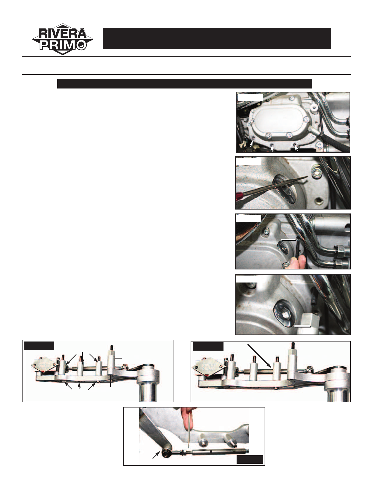
4. Remove the three(3) lower 5/16-18 socket head cap screws on the
bottom right side of the transmission. (Photo 1)
5. Remove the top front 1/4-20 socket head cap screw on the right side of
the transmission. (Photo 2)
6. Install supplied 1/4-20 set screw into the top front hole (P/N 2100-0049)
on the right side of transmission. (Photo 3)
7. Install supplied threaded spacer (P/N 2084-0079) over stud with the hex
end towards the transmission and torque to 12 foot pounds. (Photo 4)
8. Install the brake assembly onto the transmission using three(3) each
5/16-18 x 3.00” socket head cap screws (P/N 2100-0001) with
spacers (P/N 2084-0069) and one(1) each 5/16-18 x 1.00” socket
head cap screw (P/N 2100-0047). (Photo 5A)
9. Check the working of the brake pedal up & down to make sure nothing
is rubbing or hitting any of the linkage or pedal (the plunger rod will stop
when it touches the front lower spacer and at this time the master cylinder
will be bottomed out). (Photo 5B)
10. Adjust the free play in the brake lever. You should have 1/8” up & down
free play. This can be adjusted with the plunger rod (P/N 2084-0065).
Loosen jam nuts then turn the plunger to add or take away free play.
When you have 1/8” of free play lock the jam nut (P/N RIV-201) to the
rod end (P/N 2018-0099). (Photo 6)
11. Now it’s time to measure for your rear brake line and light switch. Be
sure to run the brake line away from the exhaust system and any
moving parts. Once you’ve installed the brake line you can bleed the
brake system per the O.E. manual.
12. Install your footpeg and brake pedal peg (not supplied).
13. Reinstall your exhaust system & check for clearance.
Photo 1
Photo 2
Photo 3
2100-0049
2100-0049
Photo 4
2084-0079
2084-0079
Photo 5A
OE=Original Equipment
SHCS=Socket Head Cap Screw
SFHCS=Socket Flat Head Cap Screw
2084-0069
2100-0001
2100-0047
2084-0079
2018-0099
RIV-201
Photo 5B
2084-0065
Photo 6
1108-0046 / 6-08
BRAKE SIDE ASSEMBLY. . . P/N 2084-0502
ITEMIZATION OF PARTS
* NOTE: USE BLUE LOCTITE ON ALL FASTENERS
Master Cylinder Assembly
Qty Part Number Description
1 2034-0051 Polished Master Cylinder Body Photo 1 & 2
1 2037-0001 Master Cylinder Rebuild Kit Photo 1
1 2034-0056 Polished Master Cylinder Top Cover Photo 1
1 2094-0001 Master Cylinder Top Cover Gasket Photo 1
2 2100-0112 10-24 x .500” Top Cover Screws Photo 1
1 2084-0412 Master Cylinder Assembly Photo 2
Master Cylinder Assembly to Brake Mounting Plate
Qty Part Number Description
1 2084-0063 Polished Brake Mounting Plate Photo 3
2 2100-0045 3/8-24 x 2.75” SHCS Photo 3
2 2084-0076 Spacers (Master Cylinder) Photo 4
2 RIV-318 3/8” Flat Washers Photo 4
2 3/8-24 Locknuts Photo 5A
Brake Pedal Ext. Spacer Assembly
Qty Part Number Description
1 2084-0066 Brake Pedal Ext. Spacer Photo 6
2 2084-0048 Bronze Bushings Photo 6
2094-0001
Photo 1
Photo 4
Brake Pedal Ext. Spacer Assembly to Brake Mounting Plate
Qty Part Number Description
4 2100-0113 1/4-20 x 1.00” SHCS Photo 7
1 2100-0042 1/4-20 x 1.375” SHCS Photo 7
1 2084-0071 Chrome Spacer for P/N 2100-0042 Photo 7
1 2084-0409 Brake Pedal Ext. Spacer Assembly Photo 7
2034-0051
O-Ring
2037-0001
RIV-318
2100-0112
2034-0056
Rubber
Cup Seal
Photo 2
2084-0412
Photo 5A
2084-0076
RIV-318
Photo 3
M/Cylinder
Assembly
2100-0045
Photo 7
2100-0113
2084-0063
2084-0063
2084-0076
2084-0048
Photo 6
2084-0066
2084-0071
2100-0042

Brake Side Assembly & Brake Linkage Assembly
Qty Part Number Description
1 Welded Brake Linkage Photo 8
3
1 2084-0075 Brake Shaft Spacer Photo 8 & 10
1
1 1101-0020 Thrust Washer (Small) Photo 10
1 1101-0022 Thrust Washer (Large) Photo 11
2101-0008 .125” x .750” Dowell Pins Photo 8 & 9
1100-0018 Curved Disc Spring Washer Photo 10
Master Cylinder Plunger Rod Assembly
Qty Part Number Description
1 2018-0099 Rod End 5/16-24 Female Photo 12
1 2084-0065 Plunger Rod Photo 12 & 13
1 RIV-201 Jam Nut for Rod End on Plunger Rod Photo 13
1 1101-0023 Return Spring Photo 13
1 2100-0043 5/16-24 x 1.25” SFHCS Photo 12 & 13
1 2084-0073 Spacer (Rod End) Photo 12 & 13
1 2100-0044 5/16-24 Center Locknut Photo 12 & 13
Photo 12
1101-0023
2084-0075
2084-0093
1100-0018
2084-0073
1101-0020
Photo 8
1101-0022
2101-0008
2100-0043
Photo 9
2084-0065
Photo 10
2100-0044
1101-0022
2084-0075
1100-0018
1101-0020
Photo 11
2018-0099
RIV-201
Photo 13
1101-0023
2100-0043
2100-0044
2084-0073
Brake Lever Assembly
Qty Part Number Description
1 2084-0055 Brake Lever Mounting Block Photo 14
1 2084-0053 Brake Lever Photo 14
1 2084-0073 Brake Lever Retainer Photo 15A
7 2100-0048 10-24 x 1.125” SHCS Photo 15B
1
2100-0047 5/16-18 x 1.00” SHCS Photo 15B
Installing Brake Lever Assembly to Brake Mounting Plate
Qty Part Number Description
1 Brake Mounting Plate Assembly Photo 16A/B
1 Brake Lever Assembly Photo 16A/B
Installing Spacers onto Brake Mounting Plate
Qty Part Number Description
3 2100-0001 5/16-18 x 3.00” SHCS Photo 17/18
1 2100-0047 5/16-18 x 1.00” SHCS Photo 17/18
3 2084-0069 Spacers Photo 17/18
1 2084-0079 Spacer Photo 17/18
1 2100-0049 1/4-20 x 1.50” SSS Photo 17/18
Photo 14
2084-0073
2084-0053
Photo 16A
1101-0022
Photo 18
Line-up Hole
2084-0055
2084-0069
2100-0048
2100-0049
Photo 14
Retainer
Retaining
Block
Top Front
Photo 16B
2100-0047
2084-0079
Photo 15A/B
Photo 17
2100-0001
2084-0069
2084-0079
2100-0047
2100-0049
2100-0001

COMPONENT ASSEMBLY / BRAKE SIDE
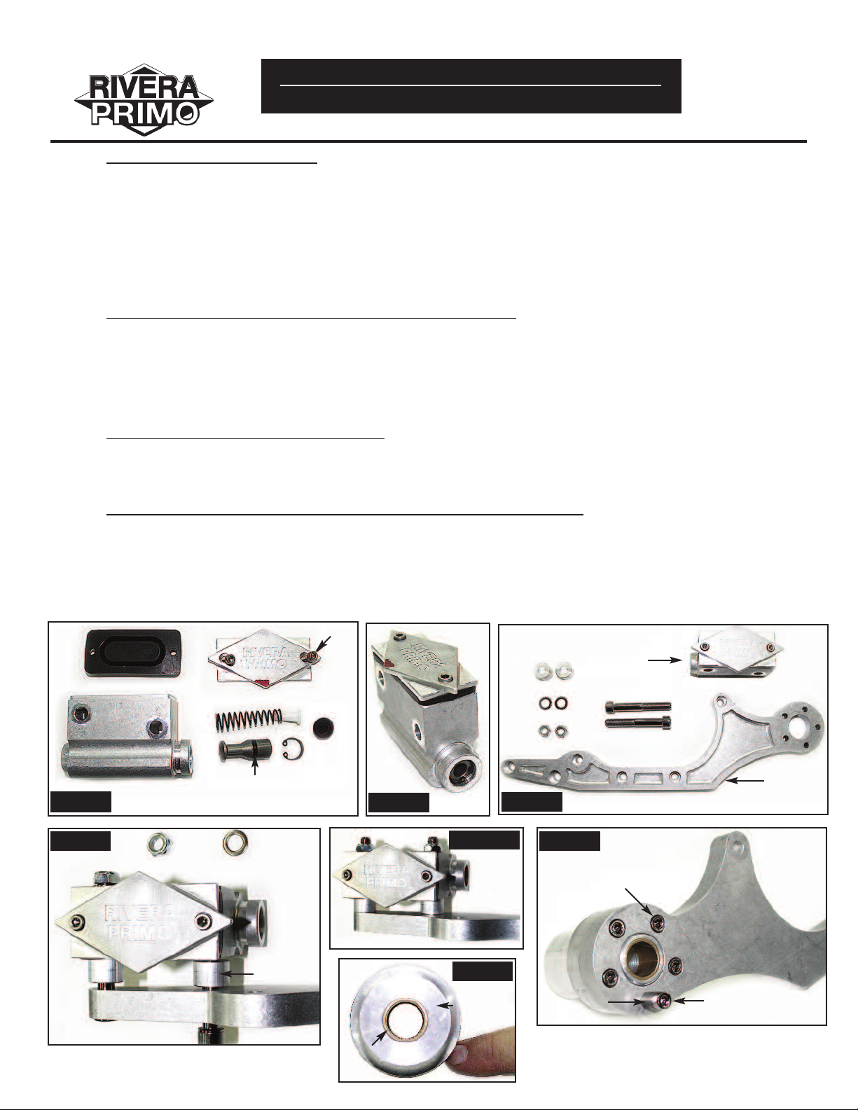
1. Master cylinder rebuild kit (P/N 2037-0001). Lubricate rubber
cup seal & o-ring on piston with DOT 5 BRAKE FLUID.
(Photo 1A)
2. Install large end of spring into the master cylinder (P/N 2034-
0051) bore with nylon pin inserted into small end of spring
followed by rubber cup seal (flat side of rubber cup seal faces
outward). (Photo 1A)
3 Spread a small amount of brake fluid in master cylinder base.
Install aluminum piston with the o-ring end facing outward and
push aluminum piston into the master cylinder bore and install
snap ring. (Photo 1B)
4. Install master cylinder top cover rubber gasket (P/N 2094-
0001) with master cylinder top cover (P/N 2034-0056) using
two(2) each 10-24 x .500” SHCS (P/N 2100-0112) and hand
tighten. (Photo 1C)
2094-0001
O-Ring
2
034-0056
2100-0112
ubber Cup
R
Seal
Photo 1A
084-0412
2
2034-0051
2084-0076
RIV-318
M/Cylinder Assy
2100-0045
1. Install two(2) each 3/8-24 x 2.75” SHCS
(P/N 2100-0045) thru the two counterbored
holes at end of brake mounting plate (P/N
2084-0063) followed by two(2) each spacers
(P/N 2084-0076). (Photo 3 & 4)
2. Now slide master cylinder onto 3/8-24 x 2.75”
SHCS followed by two(2) each washers
2084-0063
Photo 3 Photo 4
(P/N RIV-318). (Photo 4)
1. Press two(2) each bushings (P/N 2084-0048) into each end of brake pedal
ext. spacer (P/N 2084-0066). (Photo 6)
NOTE: TRY INSTALLING WELDED BRAKE LINKAGE INTO BRAKE PEDAL
EXT. SPACER. THIS WILL LET YOU KNOW IF THE BUSHINGS
NEED TO BE REAMED.
Photo 1B Photo 1C
RIV-318
M/Cylinder Assy
2084-0076
2084-0063
Photo 6
2084-0066
2084-0048
1 Install brake pedal ext. into the machined and pocketed side of brake
mounting plate. (Photo 7)
2. Install four(4) each 1/4-20 x 1.00” SHCS (P/N 2100-0113) into counterbored
holes and then slide spacer (P/N 2084-0071) onto 1/4-20 x 1.375” SHCS
(P/N 2100-0042) and torque these to 12 foot pounds. (Photo 7)
2100-0113
2084-0071
Photo 7
2100-0042

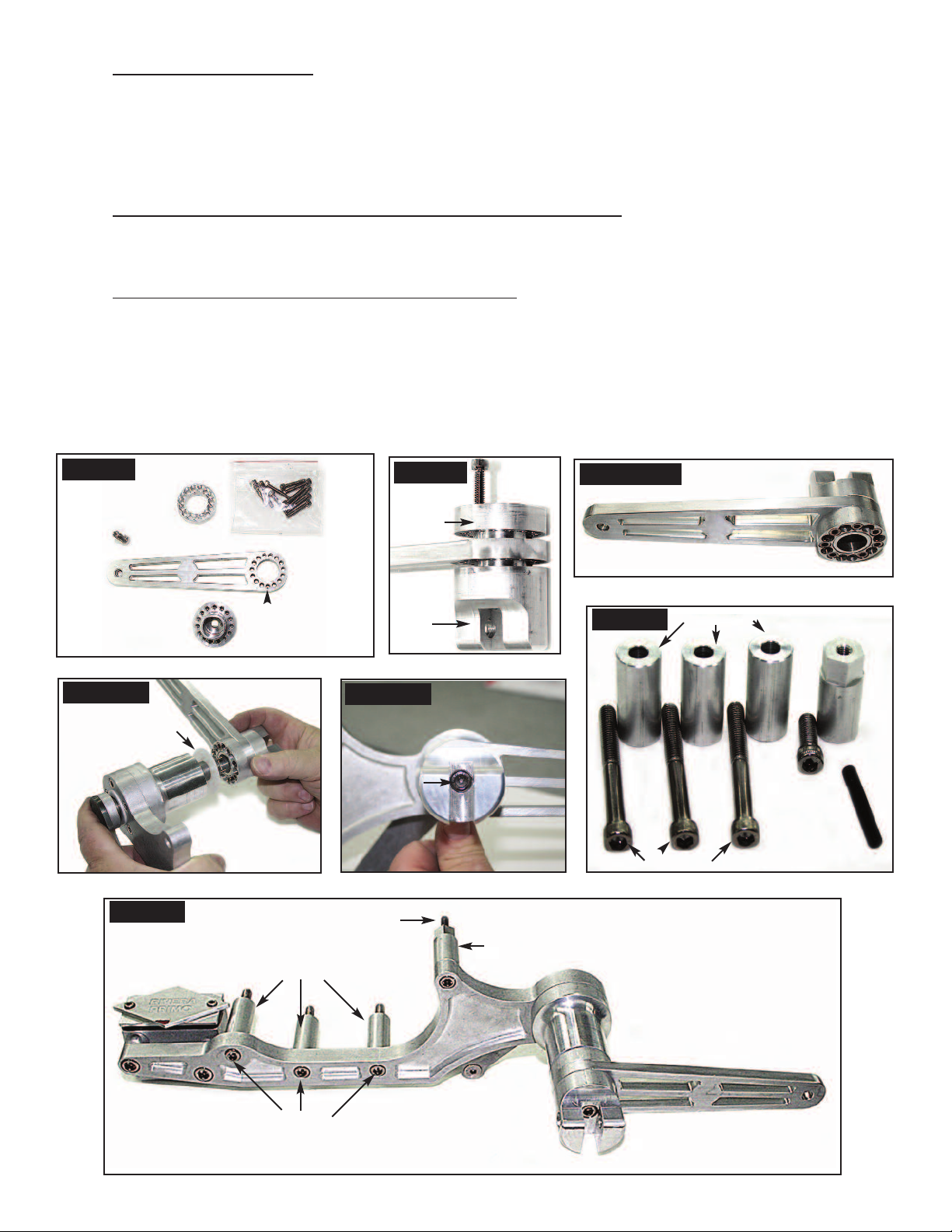
1. Install three(3) each pins (P/N 2101-0008) into the three holes on the threaed
end of welded brake linkage. Using a hammer tap the three pins until they
bottom out. (Photo 8 & 9)
2084-0075
100-0018
1
hoto 8
P
101-0022
1
hoto 9
P
2. Install spacer (P/N 2084-0075) onto welded brake linkage (flat side facing out).
Now install curved disc spring washer (P/N 1100-0018) followed by small
thrust washer (P/N 1101-0020). (Photo 10)
100-0020
1
3. Install welded brake linkage (Photo 10) onto brake mounting plate with brake
pedal ext. and master cylinder from the master cylinder side. Now slide the
large thrust washer (P/N 1101-0022) onto welded brake linkage from the
outside. (Photo 11)
2101-0008
084-0075
2
1100-0018
Photo 11
NOTE: NOTCH ON WELDED BRAKE
LINKAGE GOES BEHIND SHCS
(P/N 2100-0042) & SPACER
(P/N 2084-0071) ON BRAKE
MOUNTING PLATE. (Photo 7)
Photo 7
Photo 10
100-0020
1
1100-0022
1. Install jam nut (P/N RIV-201) onto threaded end of of plunger rod (P/N 2084-0065) followed by rod end (P/N 2018-0099). (Photo 12)
2. Install 5/16-24 x 1.25” SFHCS (P/N 2100-0043) into welded brake linkage. On the other side install spacer (P/N 2084-0073).
(Photo 13)
3. Now install spring (P/N 1101-0023) on machined end of plunger rod (P/N 2084-0065). Guide the plunger rod & spring into the
master cylinder and install rod end onto P/N 2100-0043 followed by center locknut (P/N 2100-0044). (Photo 13)
4. Torque to 30 foot pounds.
Photo 12
2084-0073
100-0043 2100-0044
2
2100-0044
2018-0099
1101-0023
1101-0023
2084-0065
RIV-201
2018-0099
Photo 13
1. Holding brake lever mounting block (P/N 2084-0055) so top front
is facing you, install brake lever (P/N 2084-0053) onto brake
mounting block lining up the top two mounting screw holes
Retainer
(NOTE: THE BRAKE LEVER WILL POINT TO YOUR RIGHT).
(Photo 14)
2. Now install brake lever retainer (P/N 2084-0073) with counter-
bored holes facing outward. Start by installing 10-24 x1
(P/N 2100-0048) in top hole and now install 10-24 x 1-
-1/8” SHCS
1
/
” SHCS
8
Retaining
Block
Top Front
in every other hole going downwards and tighten. (Photo 15A/B)
1. Install brake lever with mounting block assembly onto welded brake linkage shaft that is installed
in brake mounting plate. The top hole on the brake mounting block will go in the top pin on brake
linkage shaft with thrust washer between the two.
2. Now tap the brake lever mounting block onto the welded brake linkage with a rubber hammer.
(Photo 16A)
3. Now install
5
/
-18 x 1” SHCS (P/N 2100-0047) thru center hole in brake lever mounting block
16
and thread onto welded brake linkage. (Photo 16B)
NOTE: YOU WILL USE THE
4. Now that the unit is complete remove
5
/
-18 x 1” SHCS TO PULL THE TWO UNITS TOGETHER
16
5
/
-18 x 1” SHCS and put one(1) drop of blue loctite
16
onto threads and torque to 30 foot pounds.
Photo 14
Photo 15A/B
2084-0065
2084-0073
2100-0043
Photo 16A
1101-0022
2100-0047
Photo 16B
1. Install three(3) each 5/
-18 x 3” SHCS (P/N 2100-0001) thru brake
16
mounting plate. Then slide three(3) each spacers (P/N 2084-0069)
5
/
onto
-18 x 3” SHCS.
16
2. Install one(1) each 5/16-18 x1” SHCS (P/N 2100-0047) into top hole
and thread round end of spacer (P/N 2084-0079) onto SHCS.
Thread 1/4-20 x 1.50” SSS into hex end of spacer (P/N 2100-0049).
2100-0049
2084-0069
2100-0001
2084-0079
Photo 18
2100-0047

M
INSTALLATION PROCEDURE for BRUTE IV EXTREME
T
MID-CONTROLS (PART NO. 2084-0504)
NOTE: USE BLUE LOCTITE ON ALL FASTENERS
TORQUE 1/4” fasteners to 120 inch pounds . . . 5/16” fasteners to 30 foot pounds . . . 3/8” fasteners to 42 foot pounds
SHIFT SIDE ASSEMBLY (P/N 2084-0500) / INSTALLATION PROCEDURE
1. Remove primary covers and primary drive per O.E. manual.
2. Remove the shifter and shifter mounting plate per O.E. manual.
3. Remove block-off plug from motor plate & install supplied shifter crossover tube(P/N 2084-0050) (Photo 7A, 7B, 7C)
Photo 7A
Photo 7C
2084-0050
4. Install spring washer (P/N 1101-0018) onto shifter shaft &
then thrust washer (P/N 1101-0022). Install shifter shaft
into shifter crossover tube. (Photo 8)
5. Install motor plate onto motorcycle per your BRUTE IV
TM
EXTREME
instructions.
6. Install belt drive and clutch per your BRUTE IV EXTREME
instructions.
Photo 7B
TM
Welded
Shifter
Linkage
1101-0018
Photo 8
1101-0022
7. Install the shifter rod to the shifter linkage
and shifter arm on transmission using
two(2) each 5/16-24 x 1.00” socket head
cap screws (P/N 1100-0017) & one(1) each
5/16-24 lock nut (P/N 2100-0044). (Photo 9)
Photo 9
2100-0044
1101-0017
Shifter Rod Assy
1101-0017

. Remove block-off cap from outer belt guard. (Photo 10A & 10B)
8
f your outer belt guard does not have a block-off cap
I
you will have to finish machining the shifter crossover
tube hole. (Photo 10C)
hoto 10A
P
Photo 10B
M
9. Install the outer belt guard per BRUTE IV EXTREME
T
instructions.
10. Install thrust washer (P/N 1101-0022) over shifter shaft.
(Photo 11)
Photo 10C
Photo 11
1101-0022
11. Install shifter yoke onto shifter shaft aligning the
three(3) each dowel pins on the shaft to the yoke
using one(1) each 5/16-18 x 1.00” socket head cap
screw to pull the yoke onto the shifter shaft and torque.
(Photo 12)
12. Install footpeg and shifter peg.
13. Reinstall the battery.
Photo 12
Shifter Lever Assy

SSHIFT SIDE ASSEMBLY. . . P/N 2084-0500
ITEMIZATION OF PARTS
* NOTE: USE BLUE LOCTITE ON ALL FASTENERS
Shifter Support Tube Assembly
Qty Part Number Description
1
2 2084-0048 Bronze Bushings Photo 13
Shifter Lever Assembly
Qty Part Number Description Photo 14
1 2084-0055 Shifter Lever Mounting Block Photo 15A
1 2084-0053 Shifter Lever Photo 15B
1 2084-0073 Shifter Lever Retainer
7 2100-0048 10-24 x 1.125” SHCS
Shifter Linkage Assembly
Qty Part Number Description Photo 25
1 Welded Shifter Linkage Photo 20
3 2101-0008 .125” x .750” Dowell Pins Photo 21
1 1101-0018 Curved Disc Spring Washer Photo 22
1 1101-0020 Thrust Washer (Small) Photo 23
1 1101-0022 Thrust Washer (Large) Photo 24
1 2100-0047 5/16-18 x 1.00” SHCS
2084-0050 Shifter Support Tube Photo 13
Shifter Rod End Assembly
Qty Part Number Description Photo 26
2 2018-0099 Rod Ends 5-16-24 Female
1 2084-0080 Rod 5/16-24 Male Each End
2 1100-0017 5/16-24 x 1.00” SHCS
1 2100-0044 5/16-24 Center Locknut
Photo 13
2084-0048
Photo 15A
2084-0050
Top Front
Photo 14
2084-0073
2100-0048
2084-0053
Line-up Hole
Photo 15B
2084-0055
Line-up Hole

2101-0008
Photo 20 Photo 21
1101-0018
1101-0020
Welded Shifter Linkage
2084-0050
2084-0091
1101-0022
2100-0047
Photo 23
Photo 22
1101-0018
1101-0020
Welded Shifter Linkage
Photo 26
2018-0099
1101-0022
2084-0081
Photo 24
2018-0099
Photo 25
Shifter Linkage
Assembly

COMPONENT ASSEMBLY / SHIFT SIDE
1. Press two(2) each bushings (P/N 2084-0048) into shifter support tube (P/N 2084-0050)
NOTE: TRY INSTALLING WELDED SHIFT LINKAGE INTO SHIFTER SUPPORT TUBE.
THIS WILL LET YOU KNOW IF THE BUSHINGS NEED TO BE REAMED.
084-0050
084-0048
2
NOTE: ASSEMBLY OF SHIFT LEVER IS THE SAME AS BRAKE LEVER ASSEMBLY, EXCEPT SHIFTER POINTS TO YOUR LEFT
1. Holding shift lever mounting block (P/N 2084-0054) top front install shift
lever (P/N 2084-0053) onto mounting block lining up the top two
mounting screw holes (NOTE: THE SHIFT LEVER WILL POINT TO
YOUR LEFT). Photo 15A
2084-0072
2. Now install the shift lever retainer (P/N 2084-0072) with counterbored
holes facing outward. Start by installing 10-24 x 1.125” SHCS
(P/N 2100-0048) in top hole and now 10-24 x 1.125” install SHCS in
every other hole going downwards and tighten. Photo 15B
Photo 15A
2
100-0048
2
Top Front
Photo 15B
1. Install three(3) each pins (P/N 2101-0008) into the threaded end of
welded shifter shaft. Using a HAMMER tap the three (3) each pins until
they bottom out. Photo 21
2. Install the curved disc washer (P/N 1101-0018) onto the welded shifter
shaft, then slide on the thrust washer (P/N 1101-0020). Photo 22
3. Install the welded shifter linkage into the shifter support tube. Photo 23
4. Install thrust washer (P/N 1101-0022) onto the shaft & line-up the pin on
the welded shift linkage with the top hole on the shifter lever assembly.
Photo 24
5. Using a NO BOUNCE HAMMER give one light tap and start 5/16-18 x1.00”
SHCS (P/N 2100-0047).
Photo 21 Photo 22
1101-0020
1101-0018
2084-0050
2084-0053
Line-up Hole
2084-0054
Line-up Hole
2101-0008
1101-0018
1101-0020
Welded Shifter Linkage
Photo 23 Photo 24
1101-0022
2100-0047
1101-0022
Welded Shifter Linkage

2084-0081
2018-0099
1. Thread rod ends (P/N 2018-0099) onto the threaded rod (P/N 2084-0081) using blue loctite. When tightening the rod ends they
should both face the same way.
BRINGIN’ OUT THE BEAST !
BRINGIN’ OUT THE BEAST !
Performance upgrades are
often obscured in such a way
that you really never get what
you’re looking for. After you
peel-off all the fancy trimmings
you’re basically left with about
what you started with.
2018-0099
Rivera Primo®delivers performance, plain & simple. Every go-fast
item has been tried & tested. We
work real hard at making sure your
buck will get you somethin’!
So, join us & the thousands worldwide who’ve made it a habit of
upgrading with the best . . . you
won’t be disappointed !
Start by gettin’ your hands on a Rivera Primo®parts catalog. It’s filled with the
goods that serious riders want, products that do perform. If you don’t have one
simply call us and ask for your copy of “BRINGIN’ OUT THE BEAST”.
RIVERA PRIMO INC. 12450 WHITTIER BLVD. WHITTIER, CALIFORNIA 90602
TEL: 562-907-2600 FAX : 562-907-2606 ORDERS: 800-872-1515
www.riveraprimoinc.com
 Loading...