

HOME OF PRIMO®BELT DRIVES
INSTALLATION INSTRUCTIONS FOR PRIMO’s
BRUTE III
8mm - 1-3/4” Wide
FITS:
1986-2000
FXR, FLT & FLH
1986-89 Softails
QUALITY & PERFORMANCE SINCE 1973
TM
BELT DRIVE
t is common knowledge that a belt drive primary provides advantages & service that a standard chain drive
I
primary cannot. For dependable, high-performance, long lasting service nothing beats a modern Primo®primary Belt Drive! A long standing tradition of ”Quality & Performance” has made Primo®Belt Drive systems
the most popular in the world! The wet clutch nightmare is over, no more leaky primary, no more draining the
primary for inspection or maintenance. Carefully read & follow these instructions for a quick, convenient installation. If you have any questions please call (562) 907-2600.
IMPORTANT SAFETY NOTICE....
When performi ng an y mot orcycle work such as inst all ing a b elt d rive, secure the motorc ycle in an u pright position with convenien t acces s to the primar y dr ive . If you are wor kin g wi th the moto rcycle on a lif t ma ke s ure it is
securely fastene d to preve nt it from falling .
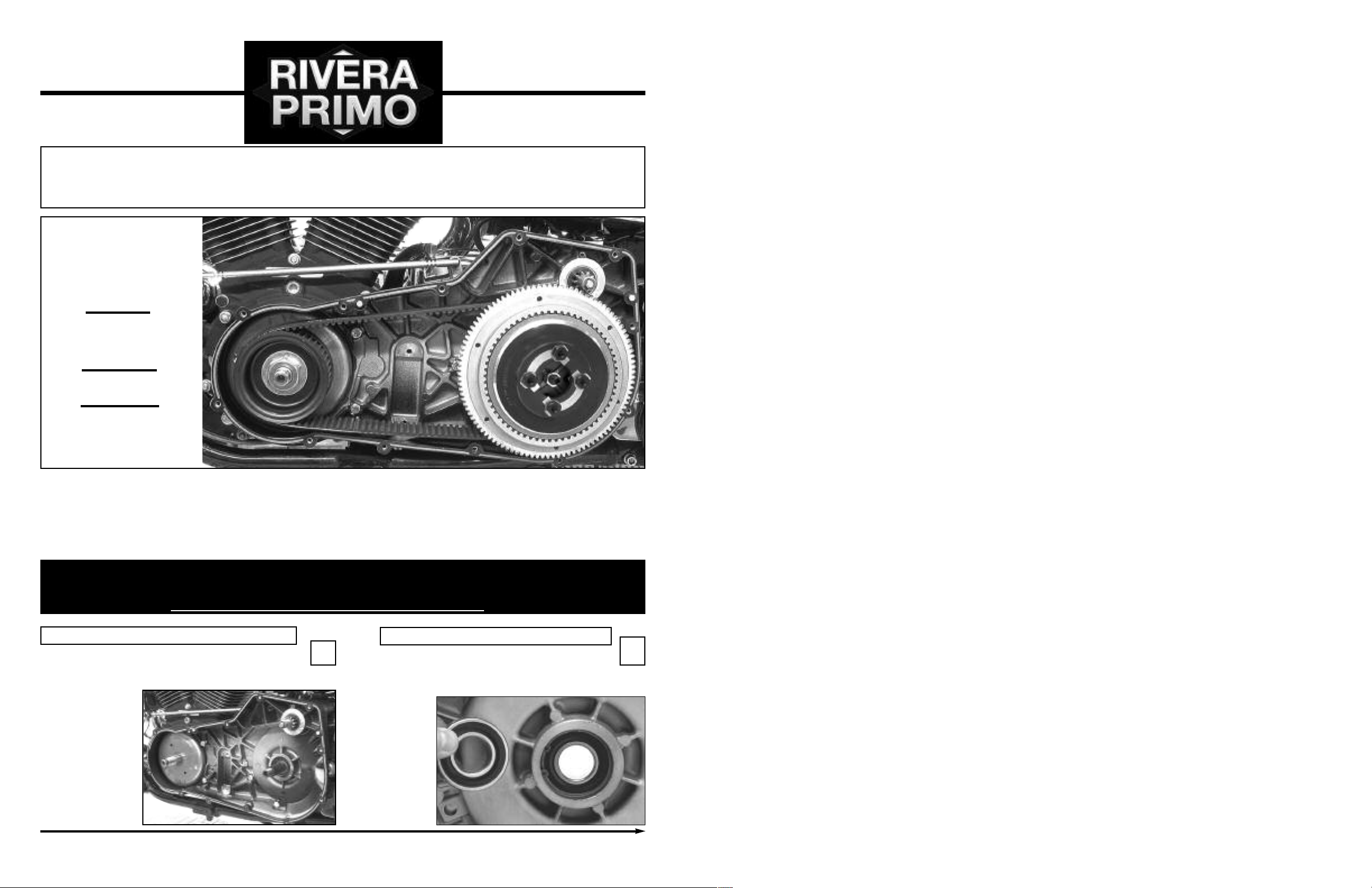
Strip the primary
Drain the primary case, remove both the inner & outer primary covers, & all OEM chain drive components from the
primary chaincase. Thoroughly clean the inner & outer
primary covers to
remove all traces
of primary fluid.
Pictured is a 1995
H arley -D a v i d s on
Dyna-Glide primary.
Remove the factory
bearing race from the
transmission mainshaft using the Jims
tool part # 34902-84.
®
Remove the battery prior to start ing the installation.
Install the sealed bearing (1018-0021)
1
Install Primo’s one-piece, sealed bearing included in the kit.
2
www.riveraprimoinc.com
1
2108-0001 Rev. 9/2014
nstall buttonhead Allen bolt
I
NOTE: Replace the OEM hex-head bolt (Dyna Glide only) with the
button-head Allen bolt provided in the kit. TORQUE THE BUTTON-
EAD BOLT TO 29 FOOT POUNDS.
H
Early FXR models may need to have some material removed from
the inner primary in the area indicated by the X’s. Check
pulley/belt clearance here before tightening clutch hub nut.
3
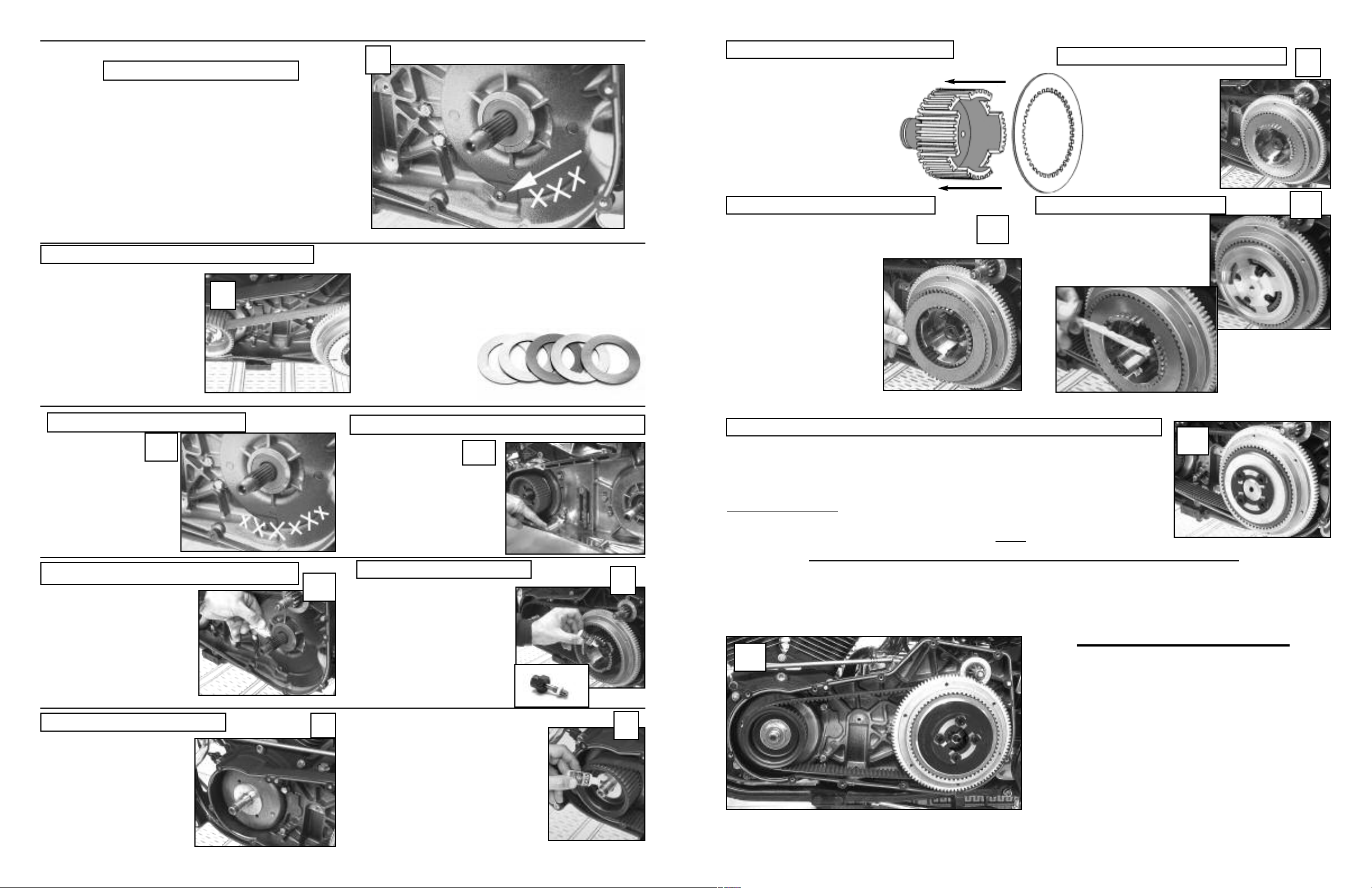
UPDATED CLUTCH HUB INFORMATION
rimo’s new clutch hub uses a .120” thick
P
teel plate at the back of the clutch pack
s
eplacing the permanently attached alu-
r
inum backing plate of the earlier model
m
lutch hub. See drawing.
c
Install the .120” thick steel plate at the
rear of the clutch pack as shown. The
clutch pack can then be installed.
.120” thick Steel Plate plate first.
After installing the .120”
steel drive plate, Install
the rest of the clutch pack
per steps 10 and 11.
9
Check pulley alignment with a straight-edge
Install front pulley. Install the
rear pulley without the belt &
check alignment as shown
(straight edge flush with rear of
ring-gear lines-up with outer
edge of front pulley). Remove
pulleys and proceed with installation. If alignment isn’t satisfactory see photo 8. The provided
.100” washer can be used to
space the front pulley outward
as needed, however it may be
nesecary to use less or more
shim.
4
Check for proper belt clearance
5
After ensuring proper pulley alignment, again
check the areas indicated
in the photo for belt and/or
pulley clearance. Always
check rear-pulley and belt
clearance here before
operating the motorcycle.
Shims are manufactured from high quality steel, precision
ground for parallel & flat surfaces to ensure perfect pulley
alignment. Correct pulley alignment & correct belt tracking
are a must for long belt life. These shims make pulley alignment easy. Shims are available in .020", .030", .050", .075" &
.100” thick dimensions, or sets of "one-of-each.”
Optional pulley shims kit
Part # 2100-0066
Includes one each of
.020”, .030”, .040”,
.050” and .100”
Check primary belt clearance here
5A
This inner primary (Early
Ev o) ha s had a tab
re moved to allow belt
clearance in the area indica ted. Most insta ll ations
require some grinding on
the outer primary webbing.
Friction Plate plate second...
Friction plate 2nd, then alternate
steel, friction, steel, friction. The
clutch plates should be installed in
the same order as delivered.
The clutch pack height is preset prior to shipment, &
should not be altered without
consulting a Primo technician.
10
Install the pressure plate
nstall the pressure plate as shown.
I
pply a generous dab of high
A
quality anti-seize to each of the
Pro-Clutch studs (as shown).
Install the locking tabs & retainer, & adjust the clutch.
Inst a ll t h e di a phra g m sp ring , spr i ng r e tain e r (b e vele d si d e in w ard agai n st
the spr i n g) lock i n g t abs, and sho u lder e d n u ts as s hown . T IGH T E N T HE
NUTS EQU A LLY U NTILTH E Y B O TTO M , & T HEN TIGH T EN T O 3 0 INC H PO U N DS
OF TOR Q UE. B end a ta b o v er e ach nu t t o k e ep i t t ight ! S p ring ad just m ent
(and c lutc h pack h eigh t ) is e s t abl i s hed p r ior t o ship p ing.
Clut c h adju s tmen t : Run th e c l utch c a b le all th e w a y out unt i l t he clu t c h
leve r touc h es th e hand l ebar g rip. T hen r u n the c ente r adju s ting s crew i n
unti l it to u ches t he pu s hrod , b ack i t out 1 / 4 tur n and t i ghte n t he j a m nut.
Adju s t the cl utch c a b le fo r 1 /8” fr e e pla y. No te: B r aid e d c lutc h c able s
requ i re li t tle o r no fr e e pla y.
11
12
Apply grease to the main-shaft splines
Apply a thin coat of grease to
the splines of the transmission
main-shaft to act as both a corrosion inhibitor, & lubricant.
The grease also acts as a cushion for the splines on the transmission main-shaft during
operation.
Install washer as needed.
A .100” washer may be
needed behind the front
pulley on some Dyna-Glide
& Softail applications.
5B
7
Install rear pulley & belt.
Install the rear pulley (clutch basket) & belt. Apply 2 drops of blue
thread-lock to the main-shaft
threads as shown. INSTALL THE
CLUTCH HUB NUT (WITH SEAL),
& TIGHTEN TO 70-80 FOOT
POUNDS OF TORQUE. The center adjustment screw/sealed nut
combination prevents transmission oil from leaking thru the
main-shaft into the clutch pack.
Install front pulley, washer & inner/outer
guides. Use 1-2 drops of blue threadlock on the threads of the motor shaft.
INSTALL & TIGHTEN NUT TO FACTORY
SPECS (150-165 FOOT POUNDS) using
a quality torque wrench or air impact
driver.
2
6
8
Belt s houl d h ave 3 / 4”-t o -1” o f u p & do w n play w hen the d r ive t r a in is co l d. Re - i nst a l l the o u ter p r imar y
cove r an d che c k b e l t c l eara n ce. I nsta l l a louv e red o r v ent e d de r by o r in s pect i on c o ver, a n d yo u ’re read y
to ride . C h eck be l t t e nsio n a f ter th e driv e t r ain re a ches no r mal op e rati n g t empe r atur e . T h e b elt sh o uld
feel s nug b u t not e xces s ivel y t igh t !
AT T EN T I ON!
13
BELT SHOULD HAVE
1/2” - TO - 1” UP & DOWN
PLAY WHEN THE DRIVE
TRAIN IS COLD!
Always check the clearance between the OUTER PRIMARY
COVER, & the belt drive assembly PRIOR TO OPERATING THE
MOTORCYCLE with a new belt drive, particularly with 95 and
later motorcycles.
3

WEAR COMPENSATION ADJUSTMENTS
Pro-Clutch clutch-pack requires no immediate adjustment, the clutch pack height having been set at the factory.
After significant mileage, some adjustment may be necessary due to normal wear. Use procedures outlined
below when adjustment is required. For best all around performance the spring should be compressed to within
.010” of being flat! This will provide best clutch lever action at the handlebar, & normal spring pressure to the
clutch pack. Slightly more clutch pressure can be gained with the diaphragm spring with .030” of spring height
(outward bow), but this will increase slightly the hand effort needed to operate the clutch. This spring configuration can be obtained by placing a small diameter washer on each of the clutch hub studs, as shown in photo B!
Three clutch spring strengths are available: A stock equivalent spring (black), a medium spring for street performance applications (silver ), & a competition spring (gold) for drag race only applications.
BRUTE III CLUTCH PACK HEIGHT = 1.715”-1.745”
If when installed the diaphragm spring is not compressed
to within .010”-to.020” of being flat (as measured at the
outer edge of the spring) optimum clutch function will not
be available. To increase compression a special .028”
washer can be installed on each shoulder nut as shown.
When adjusted correctly a typical diaphragm spring will
provide more than twice the spring pressure of it’s coil
spring counterpart. Rivera offers three different
diaphragm springs. Stock, medium, and heavy for any
street or competition applications
If when installed diaphragm spring is completely flat, or
the center of the spring is pushed past the point of being
flat, (excessive compression) correct spring function will
not be available. To reduce diaphragm spring compression, a special .022” flat washer can be installed on each
of the clutch hub studs as shown at right. Always check
the compression or curvature of the spring with a quality
straight edge.
correct
incorrect
IMPORTANT INFORMATION
LIMITED WARRANTY:
All pulleys are warranted to be free from defects in material and workmanship under normal use for a period of one year from
actual date of purchase. Seller’s liability shall be limited to repair or replacement of any materials found to be defective, free
of charge at it’s plant or authorized service depots, of specific manufactures components. It is further warranted that products
that were designed for a specific purpose, shall perform for that purpose when installed exactly as defined in the Installation
Instructions accompanying the unit. In no event shall Rivera Primo Inc. or seller be liable for consequential or special damages asserted to be attributed to malfunction of our product, for any reason including, but not limited to, damage asserted to
be from improper installation of our purchased Primary Belt Drive components.
This warranty shall not apply to any products which have been subjected to abuse, neglect or accident, nor shall it apply to
any product which has been repaired or modified by any person not specifically authorized in writing by the manufacturer.
THERE IS NO WARRANTY ON BELTS.
and used, Gates Rubber Company will not warranty any belt for length of service. Regardless of belt type, keeping your
system free of debris and other objects is most important. Remember too, improper handling of the belt can shorten service
life. Do not crimp the belt. Do not twist the belt. Do not pry the belt onto the application. If you’re shipping or storing, try to
eliminate forward and back-bending of the belt.
LIMITATION OF LIABILITY:
THERE ARE NO IMPLIED WARRANTIES WHICH EXTEND BEYOND THE DESCRIPTION ON THE FACE OF ANY SHIPMENT AND THERE IS NO IMPLIED WARRANTY OF MERCHANTABILITY AND FITNESS EXCEPT THAT THE MATERIAL
SOLD HEREUNDER SHALL BE OF SELLER’S STANDARD QUALITY, and buyer assumes all risk and liability for all loss,
damage or injury to person or property resulting from the use of said material in manufacturing processes or in combination
with other substances, or otherwise. Except as otherwise provided herein quality shall be in accordance with seller’s specifications. Final determination of the suitability of the material for the use contemplated by buyer is the sole responsibility of
buyer, and seller shall have no responsibility in connection with such suitability.
Due to the differing conditions and circumstances under which all belts are installed
RIV E R A P RIMO I n c .
12450 Whittier Blvd, WHITTIER, CA 90602
(562) 907-2600 FAX (562) 907-2606 E-mail: info1@riveraprimoinc.com
www.riveraprimoinc.com
4
 Loading...