

Page 1
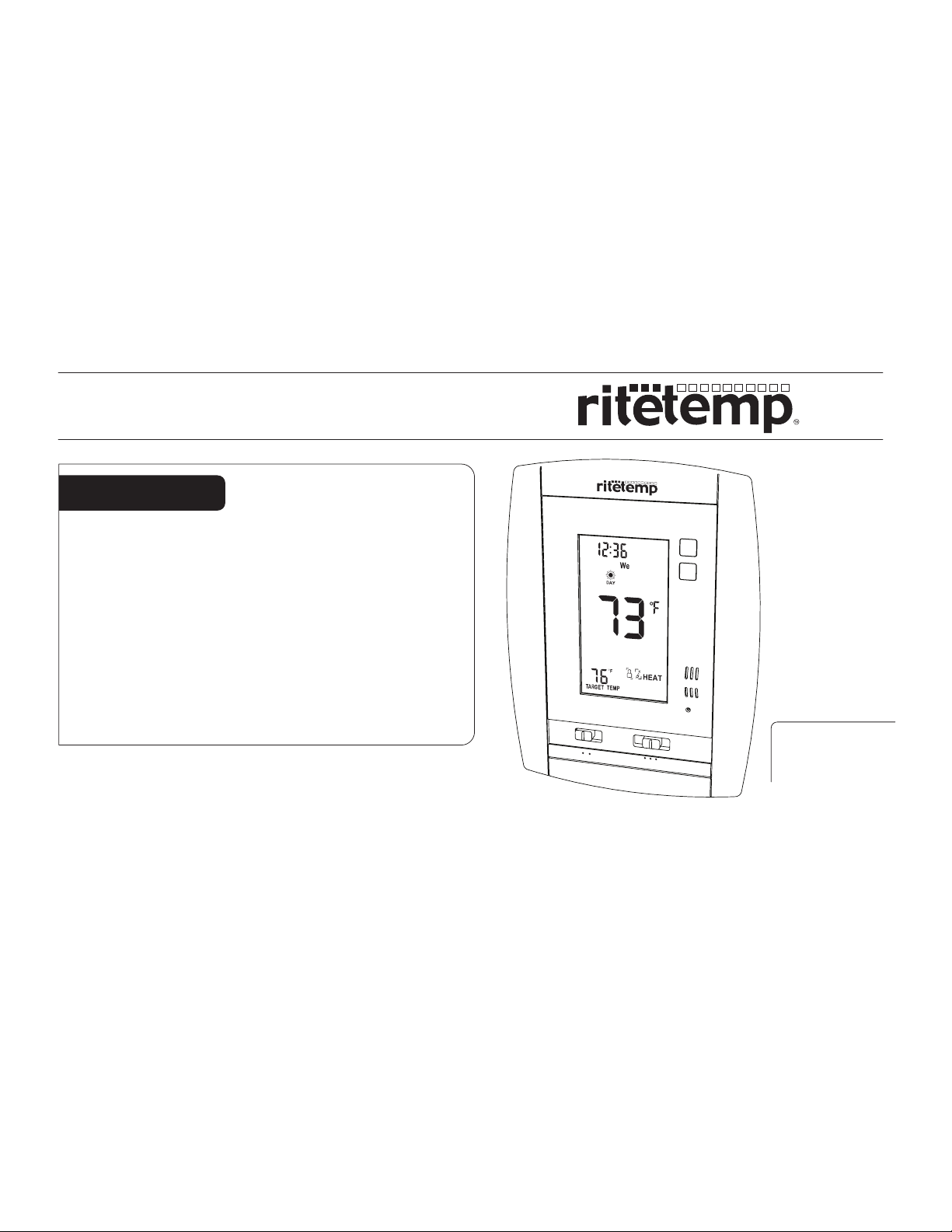
Install guide 6036
Caution
• Your thermostat is a precise instrument, handle it with care.
• Turn off electricity to the appliance before installing or
servicing thermostat or any part of the system.
• Do not turn electricity back on until work is completed.
• Do not short (jumper) across electric terminals at control on
furnace or air conditioner to test the system. This will damage
the thermostat and void your warranty.
• All wiring must conform to local codes and ordinances.
• This thermostat is designed for use with 24 volt AC and
millivolt systems. The thermostat should be limited to a
maximum of 1.0 amps; higher amperage may cause damage
to the thermostat.
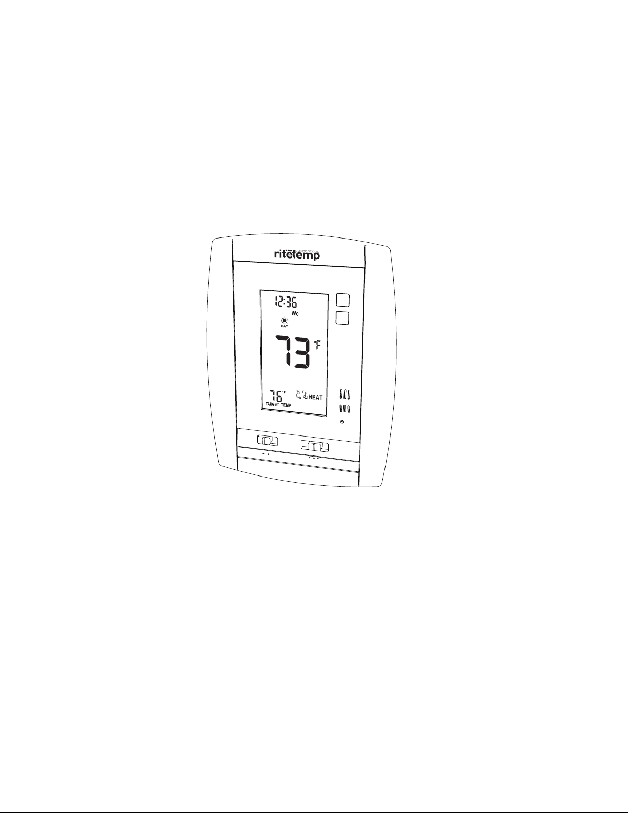
AUTO
PM
ON
FAN
COOL OFF HEAT
MENU
PROG
RESET
ENGLISH
Page 2
Install guide 6036
To avoid electrical shock and to prevent damage to the furnace, air conditioner,
Caution
and thermostat, disconnect the power supply before beginning work.
This can be done at the circuit breaker, or at the appliance.
PG
1
Tools
You will need a Phillips screwdriver, Sheet rock Saw, level, Pencil.
Location
Replacement installations - mount the new thermostat in place of the old one.
New installations - follow the guidelines listed below.
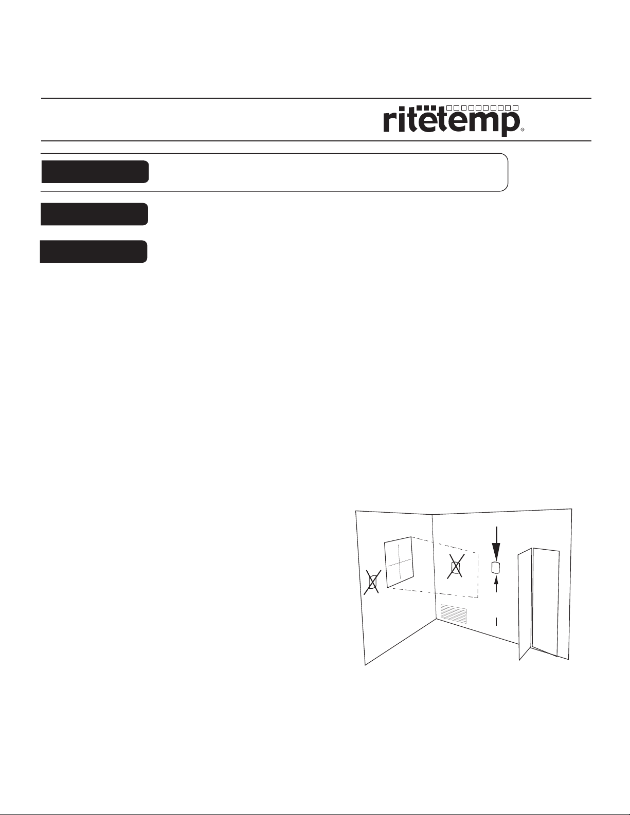
• Locate the thermostat on an inside wall, about 5 ft. (1.5m) above the floor, and in
a room that is used often.
• Locate 2" away from the nearest wall stud to allow wall box clamps to operate.
• Locate where HVAC wiring can be easily accessed.
• Do not install it where there are unusual heating conditions, such as: in direct
sunlight; near a lamp, radio, television, radiator register, or fireplace; near hot water
pipes in a wall; near a stove on the other side of
a wall.
• Do not locate in unusual cooling conditions,
such as: on a wall separating an unheated
room; or in a draft from a stairwell, door, or
window.
• Do not locate in a damp area. This can lead to
corrosion that will shorten thermostat life.
• Do not locate where air circulation is poor,
such as: in a corner or an alcove; or behind an
open door.
• Do not install the unit until all construction
work and painting has been completed.
• This thermostat does not require leveling.
PG
Good
5ft.
(1.5m)
2
Page 3
IMPORTANT : LABEL ALL WIRES
Remove old unit
BEFORE DISCONNECTING THEM!
• Switch electricity to the furnace and air conditioner
OFF; then proceed with the following steps.
• Remove cover from old thermostat. Most are snap-on
types and simply pull off. Some have locking screws on
the side or front. These must be loosened. Note the
letters printed near the terminals. Attach labels
(enclosed) to each wire for identification.
Read instructions carefully before removing any wiring from existing thermostat.
Caution
Wires must be labeled before they are removed. THERE IS NO STANDARD
COLOR CODE. When removing wires from their terminals, ignore the color of
the wires since these may not comply with any standard.
• Label the wires one at a time. You must label all the wires before you
proceed. With all wires labeled, remove them from the old unit.
• Make sure the wires do not fall back inside the wall. You can wind them
around a pencil to keep them from falling.
• Loosen all screws on the old thermostat and remove it from the wall.
B
G
W
PG
3
Cut Wall Opening
Wall
Box
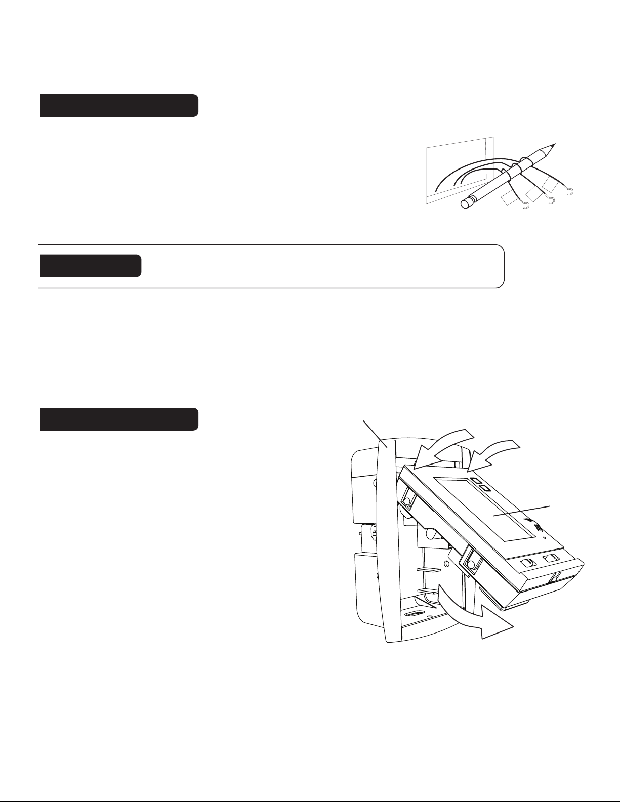
The 6036 uses a cut-in type wall box (a
type of electrical box that attaches to the
drywall, not the studs). Remove the
thermostat unit from the wall box as shown.
The Thermostat may be placed at the
existing wire location or select a better
location where you can easily relocate the
HVAC wires.
To install wall-box it is necessary to cut a
hole in the wall. Use the marking template
provided. Carefully measure where you want
the box, check for level, and mark its perimeter on the wall and
make its cutout using a drywall saw. Additional Thermostat wire
may be needed to complete installation.
Push top here
Thermostat
unit
bottom
swings out
PG
4
Page 4
Cut Wall Opening cont
Wall
Stud
• Use a stud finder to locate stud positions.
"
1/4
3
• Place the cutting template so that the 6036 will be
located between the studs [no closer than 2" from
a stud] but as close to the thermostat wires as
G
possible.
• Mark the opening for cutting in pencil. Take care
that it is level.
"
3/8
5
• Cut through craft paper surface w/ a razor knife
will give the best cut. Cut a 45o cut in each courner
to help free the pieces of wallboard you remove.
Cut the opening for the wall box using a using a
drywall saw. Take care as the box location and plumb
will be based on the precision of the wall cut out.
• Clean up edges of the hole with a file as needed.
• For best results place insulation in the wall above the opening.
RH
2"
Y
W
C
PG
5
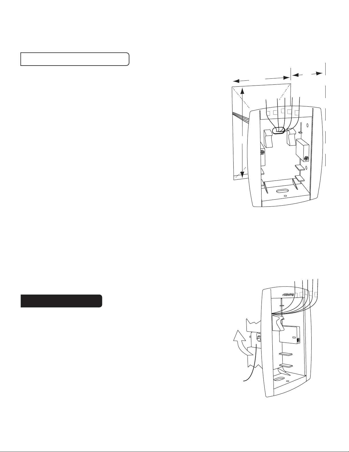
• Before placing the wall box in the opening, pull wire into the box. Select
the Wire Opening in the box that gives you the most slack in the wire. If the
wires are not long enough, you may need to lengthen some wires. If so be
sure they cannot short to each other. Wire nuts are recommended.
RH
G
Mount Wall Box
• Insert the wall-box with the RITETEMP log up.
• Tighten the 2 clamping screws located on the
sides of the wall box. Tighten until you feel
resistance. This means the clamp has made
contact with the inside of the wall board - stop
tightening when you feel this.
• Do not over tighten as it may cut into the
wall board and weaken it.
Clamp
flips out
inside wall
Y
W
C
PG
6
Page 5
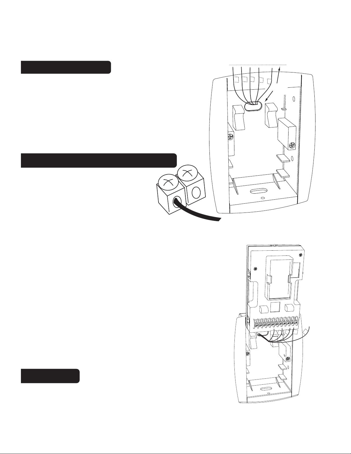
Prepare wires
With the wall box mounted position the wires
upward in the opening
• You will need 3-4" of wire for each of your
connections to the 6036.
• Fan out wires below the hole as shown.
• Trim them evenly to make inserting wires in
screw terminals easier.
Before you Connect Wires
[DO NOT connect wires until you
have cunsulted the Step by Step
digrams. ]
Please follow these guidelines for
safe and secure wire connections.
PG
7
Trim
Y
RH
G
W
C
4"
• Easy Terminals do not require stripping the wire.
• Clip any bare wire from previous installation.
• Do not to damage the labels for each wire in handling.
• Fan wires out as illustrated with 6036 above the
wall box.
• Wires will need to dress behind the 6036 and into the
wire hole
• Use the Step-By-Step diagram as your guide.
• Do not bunch wires behind 6036. Feed slack back
into the wall opening.
• Connect labeled wires only to a terminal with
corresponding letter.
Caution
Do not allow wires to touch each
other or parts on thermostat.
Y
RH
G
C
W
PG
8
Page 6
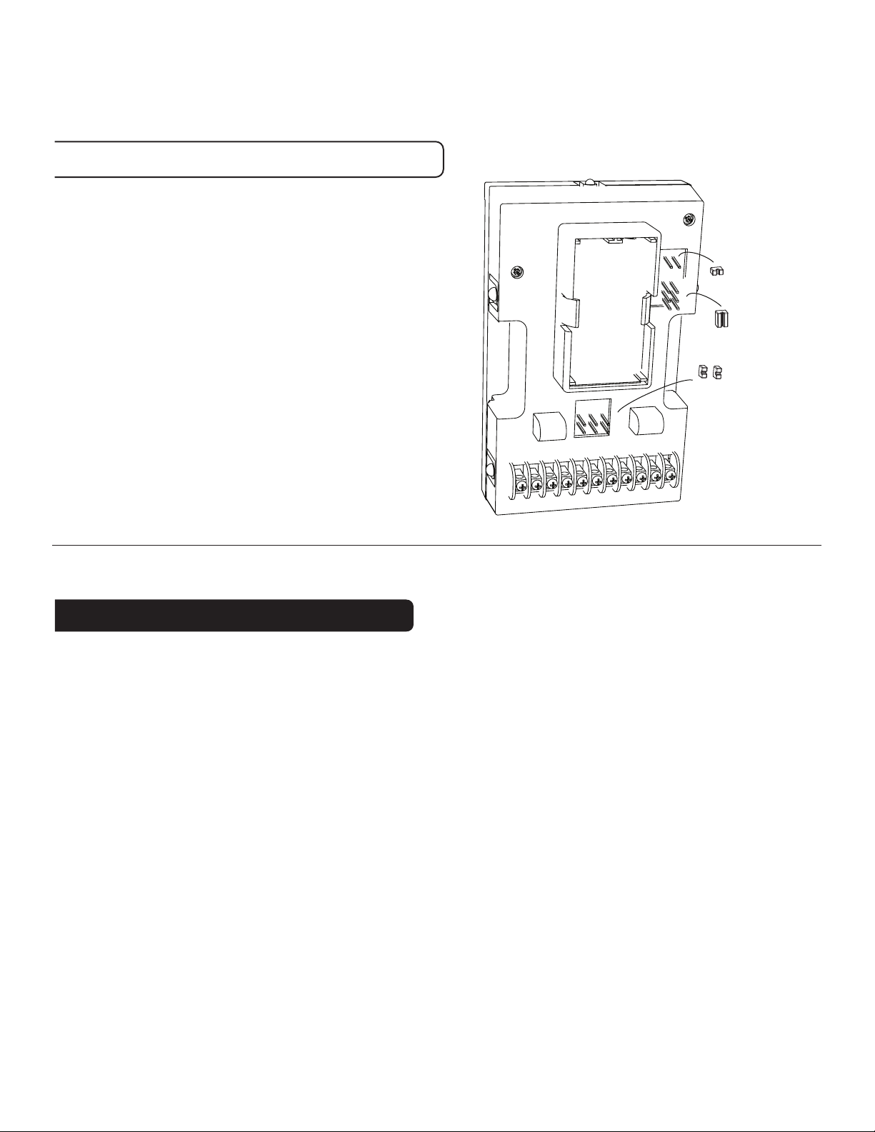
Before you Connect Wires cont
• Remember to insert the wire in the
terminal and tighten the screw securely.
PG
9
• You will need to set Configuration
Jumpers per the Step-By-Step
diagram.
• Set these jumpers first before
connecting wires.
• Needle-nose pliers may be needed to
modify jumper locations.
• ALWAYS press RESET after
changing jumpers.
What wires do you have?
1
3B
3A
5
4
2
Jumpers
On the next page you will determine which step-by-step wiring
diagram you should use. Make sure your wires are labeled. Never
guess about what a wire is, it can damage your HVAC system.
This may require you to find the 'other end' connection for each
wire on your heating or air conditioning equipment and read the
label there.
If you have a wire marked "C" it is optional. If you do connect it,
the thermostat will draw power from the C wire. This extends
battery life.
PG
10
Page 7
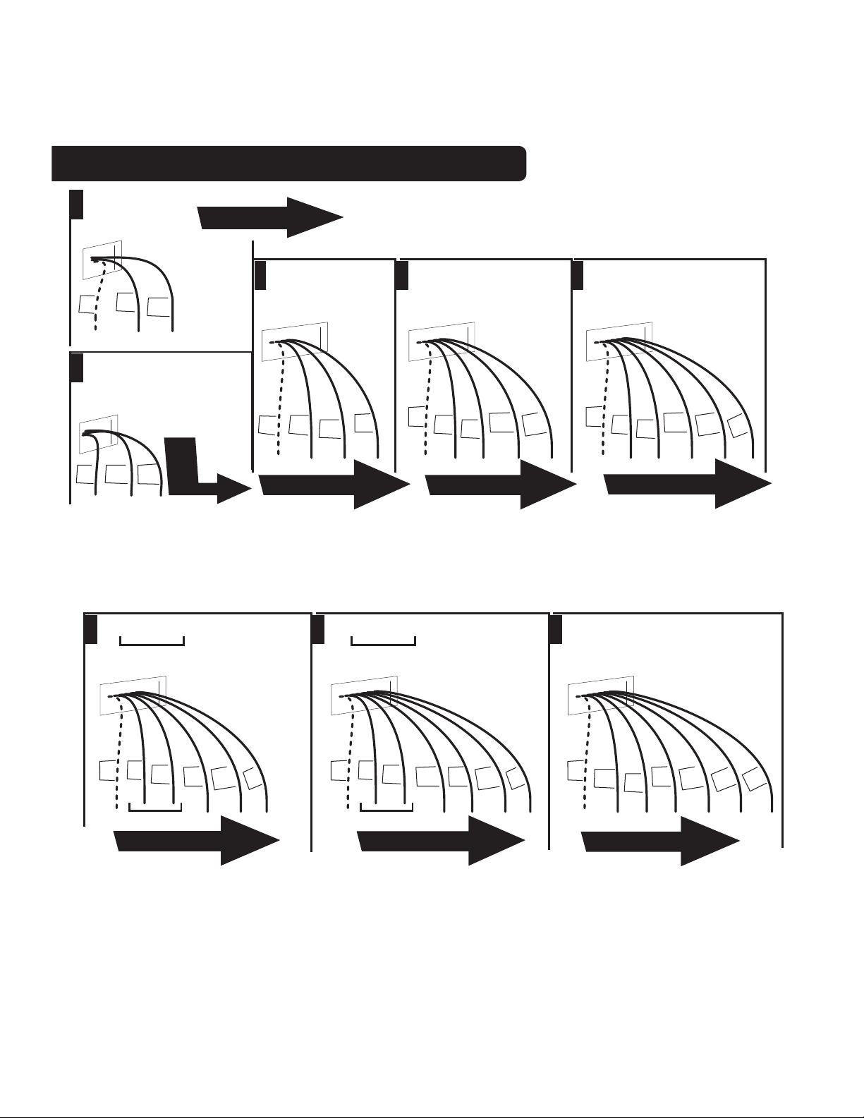
Find the set-up diagram for your system
WIRES
C W RH
From
Furnace
C
WIRES
2 Wire
Heat
W
RH
Go To Page 19
WIRES
C W RH G
From
Furnace
3 Wire
Heat
• Find the reference page with your wiring
diagram and jumper set-up information.
Remember, the C wire is optional.
WIRES
C W Y RH G
From
Furnace
4 Wire
Heat/Cool
W RH A
RH
3 Wire
Zoned
Hot Water
Go
To
A
P
AGE
26
RH
G
W
C
C
W
RH
Y
From
Furnace
W
G
WIRES
C W Y RH RC G
From
Furnace
C
W
Go To Page 22Go To Page 21Go To Page 20
RH
Y
5 Wire
Heat/Cool
RC
G
PG
11
WIRES
C B or O Y RH G
From
Furnace
4 Wire Heat Pump
w/o Aux Heat
WIRES
C B or O W2 Y RH G
From
Furnace
5 Wire
Heat Pump
WIRES
C W2 W Y Y2 RH G
From
Furnace
2 stage Cool
2 stage Heat
w/ Aux Heat
B
C
or
O
Y
RH
G
Go To Page 23
•
If your combination of wires is not above you can use the
B
C
O
or
Go To Page 24
W2
Y
RH
G
C
W
2
W
Y
Go To Page 25
wiring table on pages 24-25 to determine your connections,
or call our USA support line at 1-877-505-2353 for help.
2
Y
RH
G
PG
12
Page 8
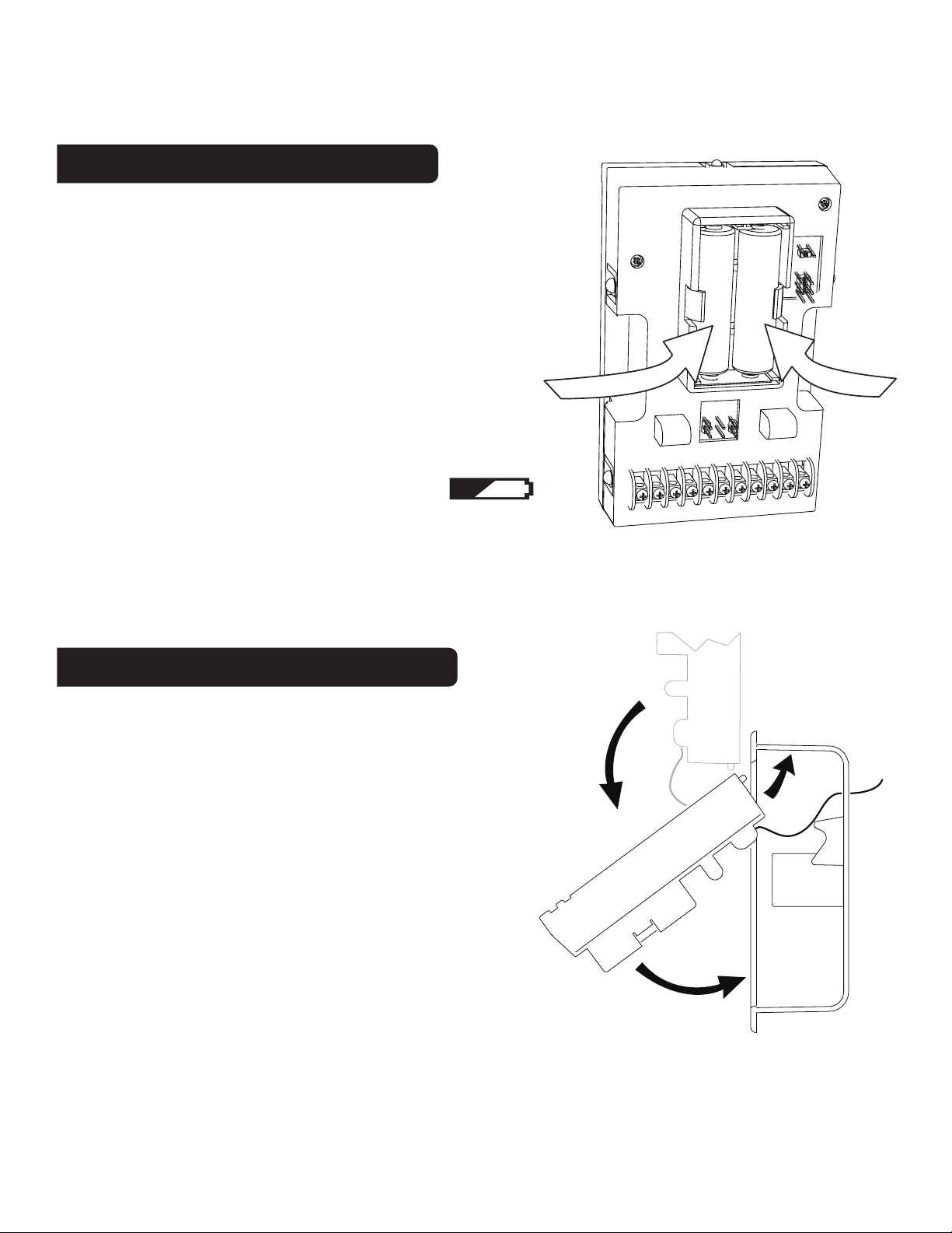
Install AA Batteries
• The 6036 requires 2 AA batteries to
PG
13
operate.
• Switch MODE switch to OFF and the
FAN switch to AUTO.
• Install 2 AA alkaline batteries
according to the polarity noted in the
compartment. LCD segments will go
on.
• Press the RESET button (under right
cover) to clear transient program
memory. NOTE: Replace the
batteries when this LOW battery
indicator appears on the display or once a
year. No backlight means low battery.
Mount the 6036 in wall box
+
AA
-
4
2
-
1
AA
+
5
• Insert the top of the 6036 into the wall
box, with the wires coming out the back of
the unit.
• Feed wires back through the wire hole as
possible.
• Swing the bottom of the 6036 into the
wall box and snap in place.
• Take great care that the wires remain
connected to the screw terminals as you
insert the 6036. Old or sub-standard wire
may break if moved excessively.
• Press the RESET button once unit is
mounted in the wall box.
PG
14
Page 9
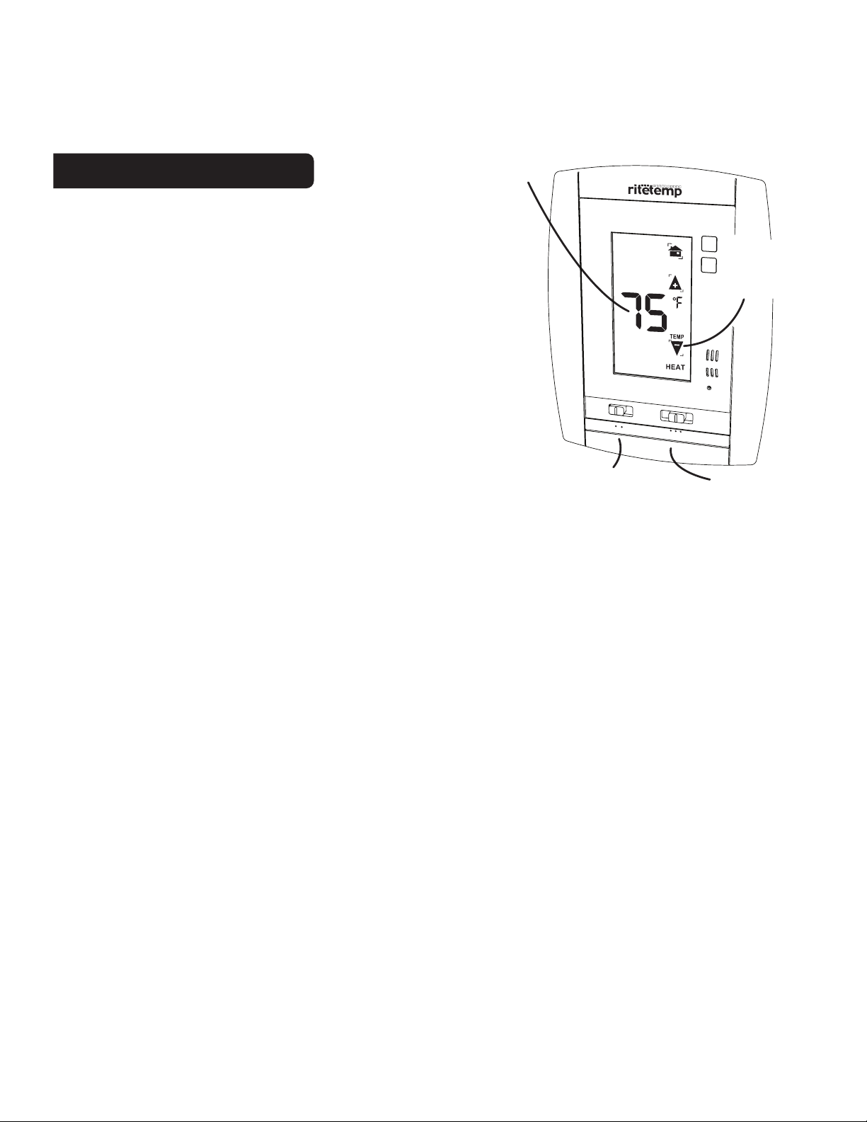
Touch
Check Unit
Temperature
Display
Follow these procedures to verify you
have correctly installed the 6036.
To check Fan:
(If you connected the G wire - fan relay)
• Switch the FAN switch to the ON position. Verify
that air is blowing from the system. Return to
AUTO position for normal operation.
To check HEAT mode:
• Set the mode switch to HEAT.
PG
MENU
Temperature
PROG
UP/DOWN
Arrows
RESET
15
• Set the fan switch to AUTO.
• Touch the room temperature and the heat target
temperature will be displayed. Use the UP arrow to
raise the target temp to 90F.
Allow the system 2
AUTO
Fan
Switch
ON
FAN
COOL OFF HEAT
Mode
Switch
minutes to respond then verify that heat is blowing from the system.
To check COOL mode:
• Set the mode switch to COOL.
• Touch the room temperature and the cool target temperature will be
displayed. Use the DOWN arrow to lower the target temperature to 50F.
Allow the system 2 minutes to respond
• Verify that cool air is blowing from the system.
• Switch MODE to OFF
Remember that handling the thermostat during installation will heat it up.
It will take 1 hour to equalize to the correct temp reading.
Congratulations, you have successfully installed your unit.
Please proceed to the OPERATING Guide to initialize the 6036.
NOTE: If you have labeled your wires, follow the correct Step-By-Step, and
these Check procedures do not operate your system call support at
1-877-505-2353
PG
16
Page 10
PG
17
Power Options
BATTERIES ONLY - This thermostat can run on batteries only using 2AA
alkaline batteries. The batteries will last at least 1 year; replace the batteries
once a year or when the low battery icon comes on the display. If the batteries
are not replaced, the thermostat will shut off the HVAC and then stop working.
24VAC - This thermostat can run on the HVAC 24VAC (C wire) if available.
As shown in the wiring diagrams, the C wire is the other side of the 24VAC
heating transformer and can be found where the other thermostat wires
connect at the wall or at the furnace. Do not use the common or ground side
of the line voltage. If the C wire is used, the batteries are then for back-up in
case of power loss only and will last much longer. With the C wire connected,
the thermostat will continue to work if the batteries die or are removed.
Calibration
NOTE:Your thermostat comes from the factory calibrated to +/- 1o of actual
temperature. It is an accurate instrument. If you want your thermostat to
display the same temperature as another thermometer in your home, you
can adjust its calibration.
To change the calibration:
Push the MENU button; the present room temperature is
displayed. To change it, use the up/down arrows and change
the displayed room temperature as you wish +/- 6F. Your
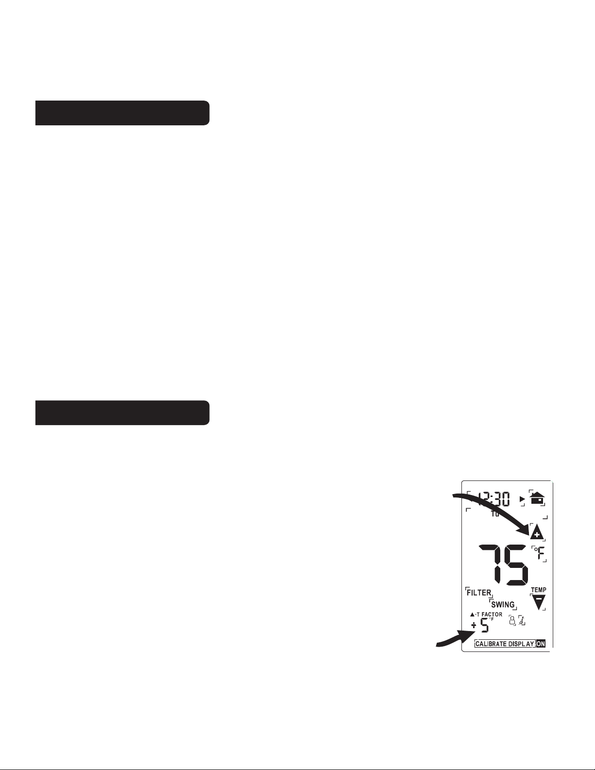
change will also be displayed on the lower left as the DELTA T
factor or number of degrees changed. Push HOME icon or
wait 60 seconds. The new room temperature will now be
displayed on the HOME screen.
NOTE: Handling the thermostat during installation will heat it up.
It will take 1 hour to equalize to the correct temp reading.
Calibrate controls
Calibrate factor
PM
PG
18
Page 11
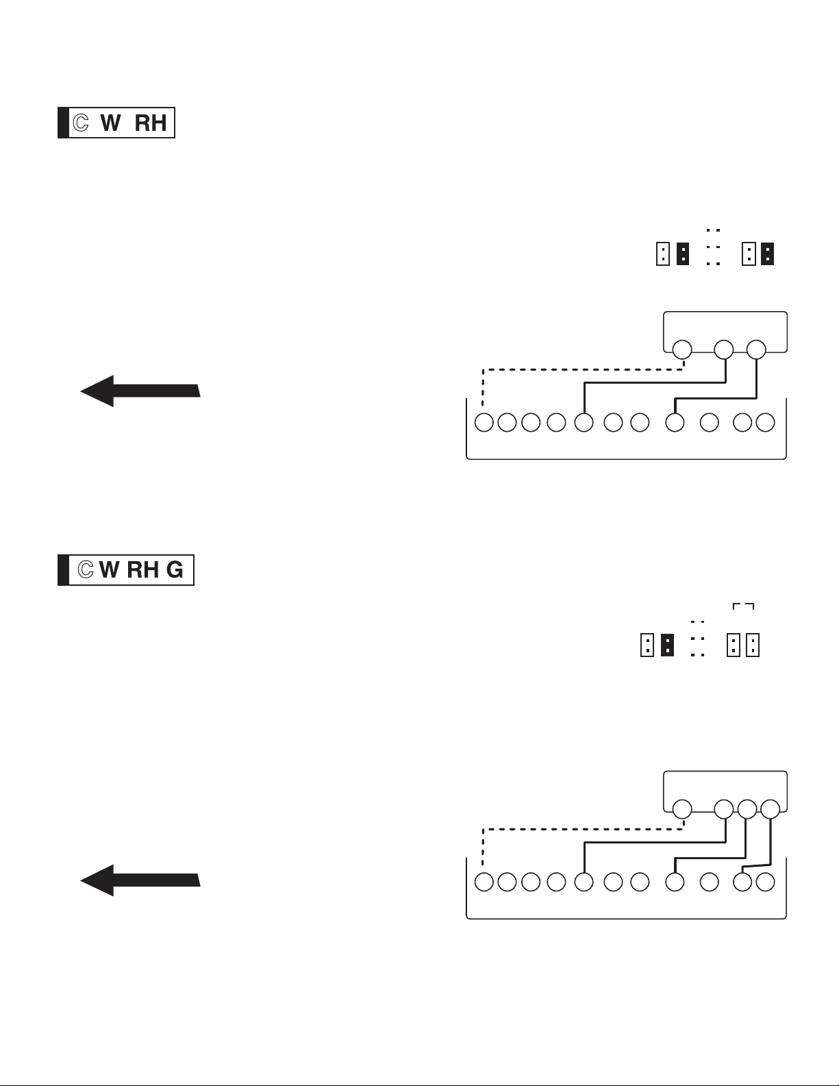
WIRES WIRES
2 WIRE HEAT Heating GAS MILLIVOLT or 24vac
PG
19
STEP 1 - Connect the R (or RH) wire to the RH terminal on
the 6036. This connects the Heater Power to the thermostat.
STEP 2 - Connect the W wire to the W on the 6036.
This connects the heater control line to the 6036.
STEP 3 - Set Config jumpers per this diagram.
Your Heater is now connected to the 6036.
Please Go To Page 9
NOTE: Wires marked with
dotted line are optional.
OPTIONAL POWER
C B O
W2
6036
W Y Y2 RH RC G A
SET
JUMPERS
3
1 2 4 5
GAS Milivolt Heat
C
W
A
B
R
3 Wire Heat
STEP 1 - Connect the R (or RH) wire to the RH terminal
on the 6036. This connects to the Heater Power .
STEP 2 - Connect the W wire to the W terminal on the
6036. This connects the heater control line to the 6036.
STEP 3 - Connect the G wire to the G terminal on the
thermostat. This connects the Fan to the 6036
STEP 4 - Set Config jumpers per this diagram. If you
have Electric heat set 4, if you have Gas or Oil set 5.
Your system is now connected to the 6036.
Please Go To Page 9
PG
20
OPTIONAL POWER
C B O
W2
W Y Y2 RH RC G A
1 2 4 5
3
SET JUMPERS
HVAC SYSTEM
C
6036
or
A
B
W
R G
Page 12
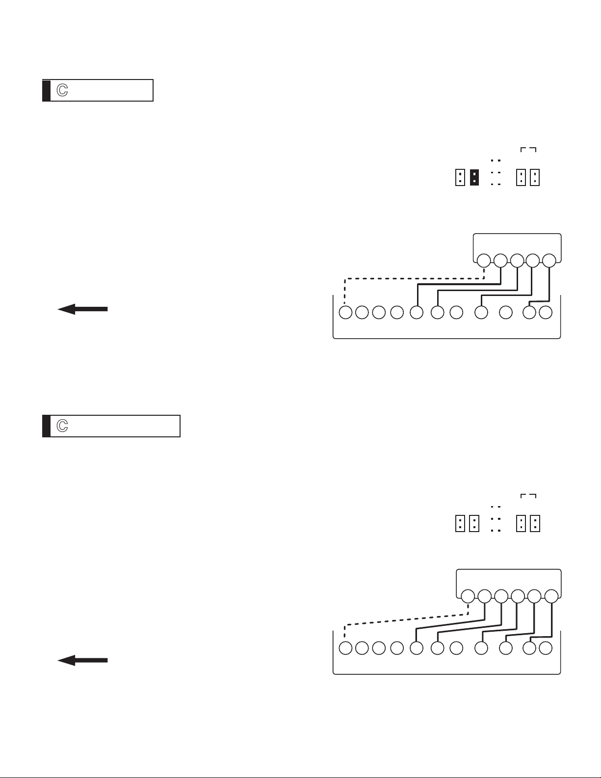
WIRES
W Y RH G
4 Wire Heat/Cool
PG
21
STEP 1 - Connect the W wire to the W terminal on the
thermostat. This connects to the heater control line.
STEP 2 - Connect the Y wire to the Y terminal on the
6036. This connects to the Cooler compressor.
STEP 3 - Connect the RH or R wire to the RH terminal on
the thermostat. This connects the Heater/Cooler Power.
STEP 4 - Connect the G wire to the G terminal on the
Thermostat. This connects to the Fan.
STEP 5 - Set Config jumpers per this diagram. If you
have Electric heat set 4, if you have Gas or Oil set 5.
Your HVAC system is now connected
OPTIONAL POWER
to the 6036.
Please Go To Page 9
6036
Terminals
C B O
W2
W Y Y2 RH RC G A
SET JUMPERS
3
1 2 4 5
HVAC SYSTEM
C
or
A
B
YWR G
WIRES
W Y RH RC G
5 Wire Heat/Cool
STEP 1 - Connect the W wire to the W terminal on the
thermostat. This connects to the heater control line.
STEP 2 - Connect the Y wire to the Y terminal on the
6036. This connects to the Cooler compressor.
STEP 3 - Connect the RH wire to the RH terminal and the
RC wire to the RC terminal on the 6036. This connects
the Heater and Cooler Power.
STEP 4 - Connect the G wire to the G terminal on the
Thermostat. This connects to the Fan.
STEP 5 - Set Config jumpers per this diagram. If you
have Electric heat set 4, if you have Gas or Oil set 5.
Your HVAC system is now connected
OPTIONAL
to the 6036.
Please Go To Page 9
PG
22
6036
Terminals
C B O
W2
SET JUMPERS
A
B
Y
or
RH RC
3
1 2 4 5
HVAC SYSTEM
W
C
W Y Y2 RH RC G A
G
Page 13
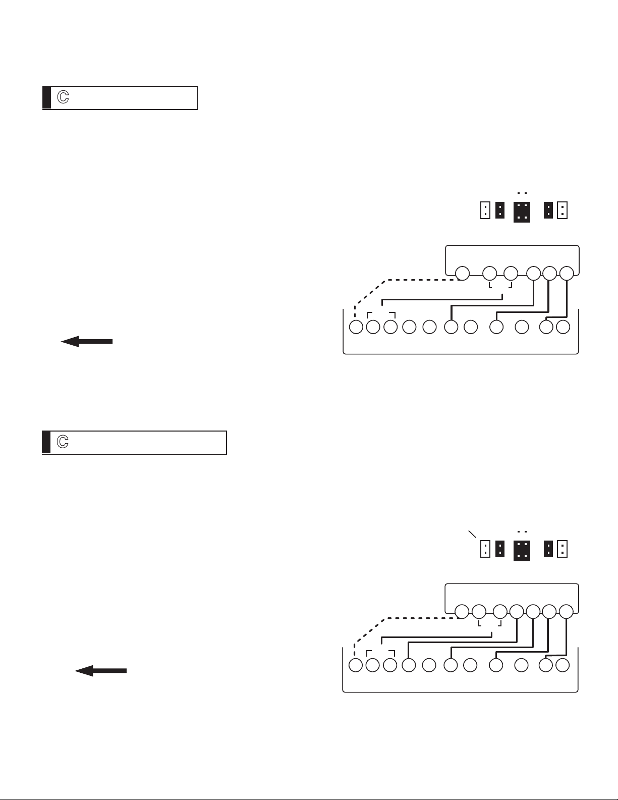
WIRES
B
or
O Y R G
4 Wire Heat Pump w/o Aux
STEP 1 - Connect O wire to the O terminal or B wire to the B terminal on
the 6036. (If you have both O and B - connect O wire to O terminal
DO NOT connect B to B terminal - see pg 24 Trane for B wire terminal)
This connects the change-over valve.
STEP 2 - Connect the Y wire to Y on the 6036.
This connects the Compressor.
1 2 4 5
SET
3
STEP 3 - Connect the R wire to RH on the 6036.
This connects to the 24vac power.
STEP 4 - Connect the G wire to the G terminal on the
6036. This connects the Fan.
STEP 5 - Set Config jumpers per this diagram.
OPTIONAL POWER
JUMPERS
HEAT PUMP SYSTEM
C
O
or
YB
A
B
PG
R G
23
Your HVAC system is now connected
or
to the 6036.
Please Go To Page 9
WIRES
B
or
O W2 Y RH G
5 Wire Heat Pump w/ Aux Heat
6036
Terminals
C B O
W2
W Y Y2 RH RC G A
STEP 1 - Connect O wire to the O terminal or B wire to the B terminal on
the 6036. (If you have both O and B -connect O wire to O terminal DO NOT
connect B to B terminal - see pg 24 Trane for B wire terminal)
STEP 2 - Connect the W2 wire to W2 on the 6036.
STEP 3 - Connect the Y wire to Y on the 6036.
STEP 4 - Connect the R wire to RH on the 6036.
STEP 5 - Connect the G wire to G on the 6036.
STEP 6 - Set Config jumpers per this diagram.
Set jumper 1 if you have Gas or Oil aux heat.
OPTIONAL POWER
Your HVAC system is now connected
?
SET
JUMPERS
C
1 2 4 5
HEAT PUMP SYSTEM
O
or
3
A
B
W2
B
Y
to the 6036.
or
R G
Please Go To Page 9
PG
24
6036
Terminals
C B O
W2
W Y Y2 RH RC G A
Page 14
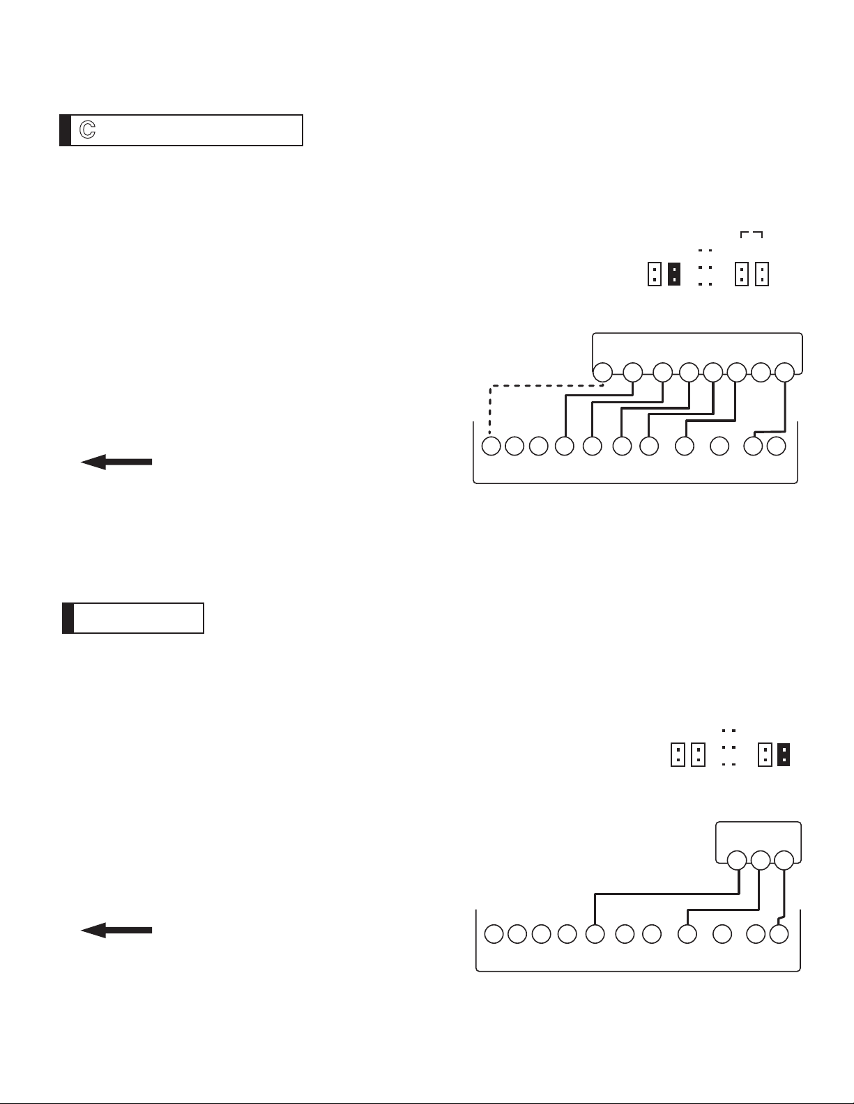
WIRES
W2 W Y Y2 RH G
2 Stage Heat and Cool
STEP 1 - Connect the W wire to the W terminal and W2 to
W2 on the 6036. This connects 2 stages of heat.
STEP 2 - Connect the Y wire to the Y terminal and Y2 wire
to Y2 on the 6036. This connects 2 stages of cool.
STEP 3 - Connect the RH or R wire to the RH terminal on
the thermostat. This connects the Heater/Cooler Power.
STEP 4 - Connect the G wire to the G terminal on the
Thermostat. This connects to the Fan.
STEP 5 - Set Config jumpers per this diagram. If you
have Electric heat set 4, if you have Gas or Oil set 5.
Your HVAC system is now connected
to the 6036.
OPTIONAL
POWER
C
SET JUMPERS
3
1 2 4 5
HVAC SYSTEM
W2
W
A
B
Y2
Y
RH
PG
or
RC
25
G
Please Go To Page 9
WIRES
6036
Terminals
C B O
W2 W Y Y2 RH RC G A
W RH [A?] 3 Zoned Hot Water - Motor Valve
Step 1 - based on your valve type
Motor driven Valve- Connect the R (or RH) wire to the RH
terminal on the 6036. Connect the W wire to the W terminal
on the 6036. Connect the remaining wire to the A terminal.
Solenoid valve -Connect the R (or RH) wire to the RH
terminal on the 6036. Connect the W wire to the A terminal
on the 6036. Connect the remaining wire to the W terminal.
STEP 2 - Set Config jumpers per this diagram.
Your system is now connected to the 6036.
SET JUMPERS
3
1 2 4 5
A
B
Motor Valve
W
R A
Please Go To Page 9
PG
26
6036
Terminals
C B O
W2 W Y Y2 RH RC G A
Page 15
PG
27
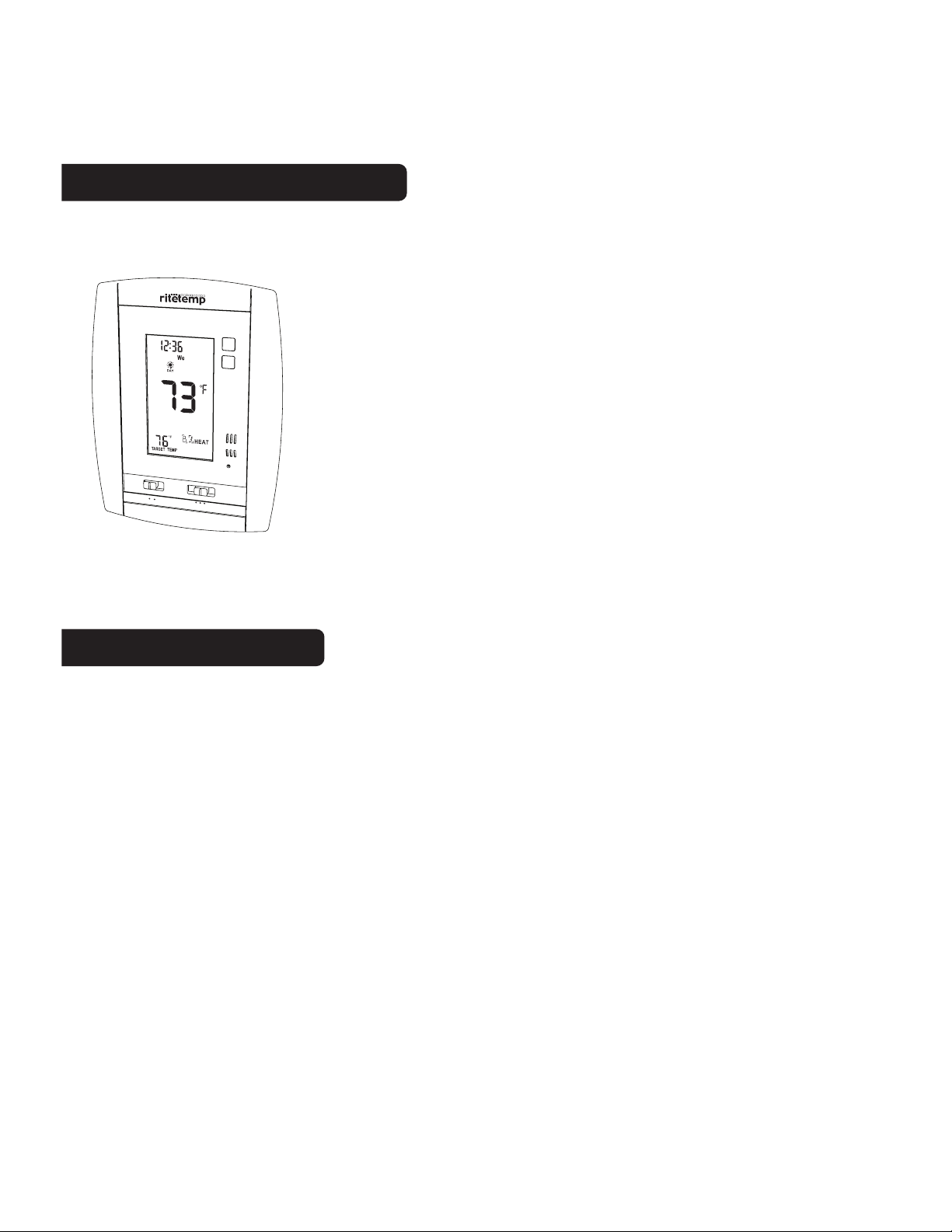
6036 Features
This thermostat can be used with all millivolt and 24VAC heating and cooling systems. It
cannot be used with line voltage systems. This thermostat is digital and your desired heat or
cool temperatures can be easily be set on the large touch screen with
the UP/DOWN arrows. A minimum 4 minute off time protects heating
and cooling systems from damage.
MENU
PM
PROG
RESET
AUTO
ON
FAN
COOL OFF HEAT
This thermostat uses a new technique called sequential staging for
more comfort with faster reaction to requested temperature changes.
When using a heat pump with Auxiliary heat, if the heat pump
cannot keep up or is defective, move the large jumper 3 from B
(lower) HEAT PUMP position to the A (upper) AUX ONLY position
(reset is not necessary). The Auxiliary heat will then be your only
source of heat. When the heat pump is again operational, be sure to
change jumper 3 back to the B position as the Auxiliary heat is more
expensive than the heat pump.
Wire Reference
Your Wires Ritetemp Terminal
R or V or VR RH and RC Single power for HEAT and COOL
RH or 4 RH Power for HEAT (RH not connected to RC)
RC RC Power for COOL (RH not connected to RC)
W W Heat control
W2 W2 2nd stage HEAT or heat pump auxiliary heat
? A 3rd wire for zoned hot water heat (see zoned)
Y Y COOL control
Y2 Y2 2nd stage COOL control
G or F G FAN control
C or X C Common 24VAC power (to power thermostat)
E Emergency heat (do not connect, tape off)
L System monitor (do not connect, tape off)
T Outdoor sensor (do not connect, tape off)
B or B Heat pump changeover (cool to heat, powered in heat)
O O Heat pump changeover (heat to cool, powered in cool)
B and O SEE NOTE
B and O
NOTE: If
there are both
B and O wires
(Trane pump
products)
DO NOT
CONNECT B
to B terminal,
connect B to C
terminal
PG
28
Page 16
PG
29
Wire Reference cont
Your Wires Ritetemp Terminal
Lennox Heat Pump
V or VR or R RH
M or Y Y
Y or W or W2 W2
F or G G
R or O O
X or X2 or C C
Trane Products [American Standard]
B C
W or W1 W2
Zoned Systems
Your Wires Ritetemp Terminal
2 wire Zoned Hot Water
R RH
W W
3 Wire Zoned Hot Water
Motor Driven Valves
R RH
W W
Y (the 3rd wire) A
3 Wire Zoned Hot Water
Solenoid Valves
R RH
W A
Y (the 3rd wire) W
Jumper Reference
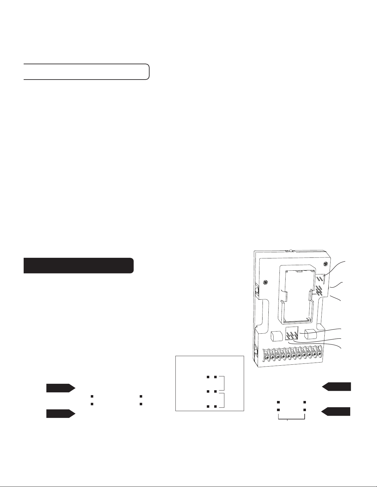
Configuration jumpers allow your
6036 to be adapted to many
different HVAC control applications.
RESET UNIT AFTER CHANGING JUMPERS
HEAT TYPE
CLOSED
AUX
Only
or
HEAT
PUMP
NORMAL
PG
CLOSED
OPEN
30
HP-AUX
TYPE
GAS/OIL
1 2
ELECT
HVAC
POWER
SINGLE
POWER(R)
POWER RH
POWER RC
1
1
3B
3A
5
4
2
FAN CONTROL
A
3
B
ELECTRIC
or H-PUMP
4
NO FAN
or
GAS or
OIL
5
CLOSED
3
3
5
4
2
OPEN
B
A
Page 17
AUTO
PM
ON
FAN
COOL OFF HEAT
MENU
PROG
RESET
Customer Support: 877-505-2353 or
Visit our web site www.ritetemp-thermostats.com
Printed in China
1709-006
 Loading...