

Page 1

Agility 2-Way Wireless Keypad
INTRODUCTION
The 2-Way keypad is used to remotely program and operate the Agility security system. Being bi-directional the 2-Way keypad receives a reply status
indication from the panel for each command that it has sent to the panel. To use functions of the keypad you can use a code or a proximity tag.
MAIN FEATURES
Bi-directional Wireless Communication
Full wireless engineer programming
Up to 3 Wireless keypads per system
S.O.S / Two way communication emergency key
Proximity tag operation
Double tamper protection (Box & Wall)
Battery economy mode
COMMUNICATION SETUP
The 2-Way keypad must identify itself to the system receiver. This can be done by using RF mode.
Setup using RF communication:
1. Set the receiver to Learn Mode by pressing the large button on the main unit for 10 seconds.
2. Send a Write message by pressing both keys
system will sound an allocation message.
3. If required to change the keypad's default settings configure the keypad's parameters according to the system installation manual.
Note :
Adding the keypad to the system can be done remotely using the configuration software by entering the serial number of the keypad.
MOUNTING THE KEYPAD
Mount the keypad on the wall using the supplied mounting bracket.
Note :
Before mounting the keypad test the keypad communication with the system.
1. Release the Mounting bracket captive screw (1).
2. Slide up the Main Unit (3) to release it from the two mounting bracket's locking tabs (2).
3. Mount the bracket.
simultaneously for at least 2 seconds. The keypad will sound a confirmation beep and the
Figure 1 Figure 2
4. Release the battery cover screw (1) and place the supplied 3 batteries.
1
Page 2

Figure 3
5. Close the battery compartment and mount the keypad to the mounting bracket in a reverse sequence to the removal.
MAIN USER OPERATIONS
The following list details the user operations from the 2-way wireless keypad. User operation can be defined to be activated by a quick mode or high
security mode that requires the use of a code or proximity tag.
In the high security mode the proximity tag can be used as a substitute for inserting a user code when the display prompts to "Insert a code".
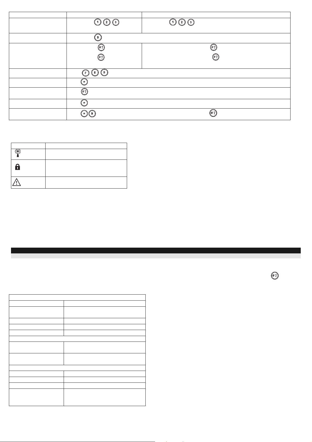
COMMON OPERATIONS
Operation Quick Operation High Security Mode1
Full Set
(Away)
Part Set
(Stay)
Full Unset
(Disarm)
1. For optimal use of the proximity tag, use it from a distance of 1-2 cm from the center of the keypad's door.
2. For Part Setting (Away Arming) with no entry delay press the
Press
Press
Press
Press followed by code or proximity tag
Press
code or proximity tag2
followed by code or proximity tag
followed by
key for two seconds
KEY OPERATION DURING PROGRAMMING MODE
Key Description
Numerical keys are used to input the numeric codes that may be required for setting,
unsetting, or used to activate specific functions
Exits from the current menu and returns to Normal Operation mode
Confirms commands and stores data
Used to browse through the menu: Scrolls up a list or moves the cursor
Changes data
ADVANCED OPERATIONS
Operation1 Quick Operation High Security Mode
Full Setting (Away)
partition 1/2/3
Part Setting (Stay)
partition 1/2/3
Unsetting (Disarming)
partition 1/2/3
Panic alarm / Service call
Fire Alarm
Emergency / Medical
Alarm
System Chime On/Off
Main unit Speaker
Volume
Select partition
press
Select partition
press
Select partition
Press both keys
Press
Press
Press the button
Press the button
Select the volume level (0=No sound, 4=Full volume)
/ / and
/ / and
/ / and press followed by the code or the proximity tag
simultaneously.
simultaneously for 2 seconds
simultaneously for 2 seconds
for 2 seconds
for 2 seconds
Select partition
tag
Select partition
tag
/ / and press followed by code or proximity
/ / and press followed by code or proximity
Set keypad LCD contrast
Press
Press
to save your selection
for 2 seconds. Use the keys to adjust the keypad's display contrast and press
2
Page 3
Operation1 Quick Operation High Security Mode
t
Output control A/B/C2
View Last Alarm
View system Status
Press button
seconds
Press button
Short press on
/ / for 2
for two seconds
: LCD display
Press button / / for 2 seconds followed by code or proximity tag
Only LCD display : Short press on
followed by code or proximity tag
Long press on
voice
Macro Activation3
Wake up keypad
Update Keypad
Parameters
Enter programming mode
Changing Keypad
Language
All operations are available while keypad is turned on (Not in Sleep Mode)
Press
Press
Press
Press
Press
for 2 seconds after changing parameters in the system
and enter the code
: LCD display +
/ / for 2 seconds
simultaneously for 2 seconds. Select the language and press to confirm.
LCD display + voice: Long press on
followed by code or proximity tag
LEDS INDICATION
Key Function
(Blue)
(Red)
(Yellow)
Communication with the panel
On: Fully or partially se
Slow flash: Exit delay
Rapid flash: Alarm
Fault in the system while the system is
unset.
SLEEP MODE
For extending the battery life of the keypad, the keypad is designed with a Sleep mode function. By default, 10 seconds after the last key has been pressed,
the keypad will turn off its display and LEDs. The time can be configured by your engineer to a maximum of 60 seconds.
REPLACING BATTERIES (see Figure 3)
1. Remove the battery compartment cover screw located at the bottom of the cover by turning screw counter clockwise.
2. Pull up the battery compartment cover according to arrow direction.
3. Pull out the battery and replace it with a new one. Pay attention to the polarity when inserting the new batteries.
4. Close the case and secure the screw to its place.
CAUTION :
Risk of explosion if battery is replaced by an incorrect type. Dispose of used batteries according to local regulations.
CHANGING KEYPAD PARAMETERS
Any change performed in the definition of the keypad parameters requires to update the keypad as well. This is performed by pressing the key for 2
seconds. Doing so, the panel will send an update to the keypad
TECHNICAL SPECIFICATION
Electrical
Battery Type CR123, 3V lithium battery (x 3)
Current Consumption Stand by current 10µA,
Max current 100 mA
Frequency 868.65 MHz
Modulation Type OOK
Typical Battery Life 3 years
Physical
Dimension (HxWxD) 150 mm x 125 mm x 45 mm
(5.9 x 4.9 x 1.77 inches)
Weight (Including
batteries)
Environmental
RF Immunity According to EN50130-4
Operating temperature -10°C to 40°C (14°F to 104°F)
Storage temperature -20°C to 70°C (-4°F to 158°F)
Compliance Statement EN50131-1, EN50131-3 Grade 2
0.395 kg
EN50130-5 Environmental class II
EN50131-6 Type C
3
Page 4

PRODUCT ORDERING INFORMATION
R
P/N Description
W132KPPW31A Agility 2-Way Wireless Square LCD Keypad, 868MHz
RTTE Compliance Statement
Hereby, RISCO Group declares that this equipment is in compliance with the essential requirements and other relevant provisions of Directive 1999/5/EC.
For the CE Declaration of Conformity please refer to our website: www.riscogroup.com
.
FCC Note
This equipment has been tested and found to comply with the limits for a Class B digital device, pursuant to Part 15 of the FCC rules. These limits are
designed to provide reasonable protection against harmful interference in a residential installation. This equipment generates, uses and can radiate radio
frequency energy and, if not installed and used in accordance with the instructions, may cause harmful interference to radio communications. However,
there is no guarantee that interference will not occur in a particular installation. If this equipment does cause harmful interference to radio or television
reception, which can be determined by turning the equipment off and on, the user is encouraged to try to correct the interference by one or more of the
following measures:
a) Reorient or relocate the receiving antenna.
b) Increase the separation between the equipment and receiver.
c) Connect the equipment to an outlet on a circuit different from that to which the Receiver is connected.
d) Consult the dealer or an experienced radio/TV technician.
FCC ID: JE4RW132KP
IC: 6564A-RW132KP
FCC Warning:
The manufacturer is not responsible for any radio or TV interference caused by unauthorized modifications to this equipment. Such modifications could
void the user's authority to operate the equipment.
RISCO Group Limited Warranty
RISCO Group and its subsidiaries and affiliates ("Seller") warrants its products to be free from defects in materials and workmanship under normal use for
24 months from the date of production.
Because Seller does not install or connect the product and because the product may be used in conjunction with products not manufactured by the Seller,
Seller can not guarantee the performance of the security system which uses this product.
Sellers' obligation and liability under this warranty is expressly limited to repairing and replacing, at Sellers option, within a reasonable time after the date
of delivery, any product not meeting the specifications.
Seller makes no other warranty, expressed or implied, and makes no warranty of merchantability or of fitness for any particular purpose. In no case shall
seller be liable for any consequential or incidental damages for breach of this or any other warranty, expressed or implied, or upon any other basis of
liability whatsoever. Sellers obligation under this warranty shall not include any transportation charges or costs of installation or any liability for direct,
indirect, or not be compromised or circumvented; that the product will prevent any persona; injury or property loss by intruder, robbery, fire or otherwise;
or that the product will in all cases provide adequate warning or protection. Buyer understands that a properly installed and maintained alarm may only
reduce the risk of intruder, robbery or fire without warning, but is not insurance or a guarantee that such will not occur or that there will be no personal
injury or property loss as a result.
Consequently seller shall have no liability for any personal injury, property damage or loss based on a claim that the product fails to give warning.
However, if seller is held liable, whether directly or indirectly, for any loss or damage arising from under this limited warranty or otherwise, regardless of
cause or origin, sellers maximum liability shall not exceed the purchase price of the product, which shall be complete and exclusive remedy against seller.
No employee or representative of Seller is authorized to change this warranty in any way or grant any other warranty.
WARNING: This product should be tested at least once a week.
Contacting RISCO Group
RISCO Group is committed to customer service and product support. You can contact us through our website www.riscogroup.com or as follows:
United Kingdom & Eire
Commerce House
Whitbrook Way
Stakehill Distribution Park
Middleton
Manchester
M24 2SS
Tel (UK): 0161-655-5500
Tel (Eire) : 0376-680-5903
technical@riscogroup.co.uk
All rights reserved.
No part of this document may be reproduced in any form without prior written permission from the publisher.
© RISCO Group 02/2014 5IN2179
4
 Loading...