

Page 1
RISCO Group
Access Control Installer Station
User Manual
Page 2

User Manual for ACIS Version
About This Manual
Purpose
This manual has been written to help you understand and use the Access Control Installer Station (ACIS)
application. It presents the operational details and functional capabilities of the application.
Intended Audience
This manual is primarily intended for Installers who will use the ACIS application to register and configure
Proxies, Controllers and Doors. Installers can also create and manage Sections, create other installers and
generate section level reports.
Prerequisites for Use
Basic understanding of Access Control System is required. Basic understanding of Windows and GUI operations
is required. Knowledge of Web-based applications is essential. Basic knowledge of configuration of devices and
network addresses is essential.
Organisation of the Manual
The information in this document is organised as follows:
About ACIS introduces ACIS. It provides the software and hardware details required for ACIS.
Getting Started describes how to log on and log off from ACIS. It also provides an overview of the activities that
you need to perform after you set up firmware devices at the client side.
Registering Proxy describes the process to register and configure Proxy.
Registering Controller describes the process to register and configure Controller.
Door Configuration describes the process to configure Doors after controllers are configured.
Performing Built in Test for a Proxy describes how to test the Proxy from ACIS.
Performing Built in Test for a Controller describes how to test the Controller from ACIS.
Downloading Firmware describes the process to upgrade the firmware version.
Adding Locations describes the steps to add, rename and delete the location in ACIS.
Adding Sections describes the process to add new section.
Creating and Editing Installer Profiles tells you how to create new installers and edit the existing ones.
Generating Section Level Reports describes the reports that can be generated in ACIS.
Contact provides the contact details of Risco.
Glossary provides explanation for terms used in this manual.
Index of the terms, concepts and tasks in the manual are provided in this section.
Uncontrolled when printed © RISCO Group i
Page 3

Typographical Conventions
The typographical conventions used in this manual are:
Convention Indicates Example
User Manual for ACIS Version
Command and Screen
element names
URLs and Hyperlinks URLs and hyperlinks. http://www.riscogroup.com
<Text> Examples are placed in angular
Cross-reference
System Messages
Buttons, check boxes, option
buttons, etc. Commands that you
choose from the menus or dialog
boxes appear in title case and in bold
font.
brackets. User needs to replace them
with appropriate options.
Cross-references are marked in
orange and made bold.
System messages, alerts and error
messages appear in bold and italics.
Click Next after choosing the
option Every one or Just Me
Replace localhost with <Server
Name>.
For details, see Glossary.
The system displays a message, “No
proxy with the given Reference
Number exists”
Feedback and Suggestions
Home: http://www.riscogroup.com
Email: support@riscogroup.com
Uncontrolled when printed © RISCO Group ii
Page 4

User Manual for ACIS Version
Contents
1 ABOUT ACIS .................................................................................................................................. 1
2 GETTING STARTED WITH ACIS .................................................................................................... 3
2.1 Before Using ACIS ..................................................................................................................... 3
2.2 Logging on to ACIS .................................................................................................................... 3
2.3 Logging Off from ACIS .............................................................................................................. 5
2.4 Overview of the Activities in ACIS............................................................................................. 5
3 REGISTERING PROXY ................................................................................................................... 7
3.1 Register Proxy ............. ......................... ......................... ......................... ......................... ........... 7
3.2 Configure Proxy ....................................................................................................................... 12
3.3 Delete Proxy ............................................................................................................................. 17
3.4 Add a Template Proxy .................. .............................. ............................... .............................. . 18
3.5 Replace Proxy .......................................................................................................................... 21
3.6 Transfer Proxy .......... ............................... .............................. ............................... .................... 23
3.7 View Action Log ....................................................................................................................... 25
4 REGISTERING CONTROLLER ..................................................................................................... 27
4.1 Register Controller ................. ............................... .............................. ............................... ...... 27
4.1.1 Configure Controller ........................................................................................................... 30
4.1.2 Configure Relay Details ...................................................................................................... 32
4.1.3 Configure Sensor Details .................................................................................................... 34
4.1.4 Configure Reader Details ................................................................................................... 36
4.2 Door Configuration .................................................................................................................. 37
4.2.1 Basic .................. ............................ ............................ ............................ ............................ 37
4.2.2 Devices .............................................................................................................................. 39
4.2.3 Events ................... ................... .................... ................... .................... ................... ...... ...... 43
4.3 Duplicate the Controller ........................................................................................................... 44
4.4 Delete a Controller ................................................................................................................... 45
4.5 Add a Template Controller ....................................................................................................... 46
4.5.1 General ........................................................................................................................ ...... 46
4.5.2 Relay Details ...................................................................................................................... 48
4.5.3 Sensor Details .................................................................................................................... 49
4.5.4 Readers Details .................................................................................................................. 50
Uncontrolled when printed © RISCO Group iii
Page 5

User Manual for ACIS Version
4.6 Replace Controller ................................................................................................................... 54
4.7 Transfer Controller .............. ............................... ............................... ................................. ...... 57
5 PERFORMING BUILT-IN TEST FOR PROXY ............................................................................... 61
6 PERFORMING BUILT-IN TEST FOR CONTROLLER ................................................................... 64
7 DOWNLOADING FIRMWARE ....................................................................................................... 66
7.1 Upgrade Proxy ................................................................................................................... ...... 66
7.2 Upgrade Controller .................................................................................................................. 67
7.3 Tasks ........................................................................................................................................ 70
8 ADDING A LOCATION .................................................................................................................. 72
8.1 Add a Location ......................................................................................................................... 72
8.2 Rename a Location .................................................................................................................. 73
8.3 Delete a Location ............................................................................................................... ...... 74
9 ADDING A SECTION .................................................................................................................... 75
9.1 Add Section .............................................................................................................................. 75
9.1.1 LDAP Server Configuration ..................... ............................... .............................. ............... 77
9.2 Edit Section .............................................................................................................................. 78
10 ADDING AND EDITING AN INSTALLER PROFILE .................................................................. 80
10.1 Add an Installer Profile ............................................................................................................ 80
10.2 Edit Installer Profile ................................................................................................................. 83
11 GENERATING SECTION LEVEL REPORTS ............ ............................... ............................... ... 86
11.1 As Built Report ......................................................................................................................... 86
11.2 Proxy Configuration ................................................................................................................. 88
11.3 Controller Configuration .......................................................................................................... 90
11.4 Door Configuration .................................................................................................................. 91
11.5 System Parameters .................................................................................................................. 94
GLOSSARY .......................... ............................... .............................. ................................................ ... 96
Uncontrolled when printed © RISCO Group iv
Page 6

User Manual for ACIS Version
INDEX ............. ......................... ......................... ......................... ......................... ........... ....................... 99
RISCO GROUP LIMITED WARRANTY ............................................................................................... 101
CONTACTING RISCO GROUP ........................................................................................................... 102
Uncontrolled when printed © RISCO Group v
Page 7

User Manual for ACIS Version
List of Tables
TABLE 1: CONFIGURE PROXY ................................................................................................................ 13
T
ABLE 2: ADD TEMPLATE PROXY ........... ......................... ......................... ......................... .................... 19
T
ABLE 3: CONFIGURE CONTROLLER ...................................................................................................... 31
ABLE 4: CONFIGURE RELAY ................................................................................................................ 33
T
T
ABLE 5: CONFIGURE SENSOR ............................................................................................................... 35
ABLE 6: CONFIGURE READER .............................................................................................................. 36
T
T
ABLE 7: CONFIGURATION OF BASIC DEVICES ......... ........ ........ ......... ........ ........ ......... ........ ........ ......... ... 38
T
ABLE 8: DEVICE CONFIGURATION ......... ... .. ... ... ... ... .. ... ... ... ... .. ... ... ... .. ... ... ... .. ... ... ... ... .. ... ...... .. ... ... ... ... .. . 40
ABLE 9: RELAY MODES ....................................................................................................................... 41
T
ABLE 10: EVENTS CONFIGURATION ..................................................................................................... 44
T
ABLE 11: ADD TEMPLAT E CONTROLLER .................. ......................... ......................... ......................... . 47
T
T
ABLE 12: ADD A SECTION ........................ ......................... ......................... ......................... ................. 76
List of Figures
FIGURE 1: LOGIN SCREEN ................. ............................... .............................. ............................... ........... 4
IGURE 2: ACIS HOME PAGE .... .................... ................... ................... .................... ................... .............. 5
F
F
IGURE 3: ACTIVE PROXIES IN A SECTION ................ ........ ........ ......... ........ ........ ......... ........ ........ ......... ..... 8
F
IGURE 4: SECTION HOME PAGE ................ ............................ ........................... ............................ ........... 9
F
IGURE 5: REGISTER PROXY .................................................................................................................. 10
IGURE 6: PROXY REGISTRATION ON ENTERING ALL THE VALUES ..... ................... .................... .............. 11
F
IGURE 7: SUCCESS MESSAGE ON PROXY REGISTRATION ............ ............................ ............................ ... 12
F
F
IGURE 9: CONFIGURE PROXY ............................................................................................................... 13
IGURE 10: PROXY CONFIGURED SUCCESSFULLY .................................................................................. 16
F
F
IGURE 11: CONNECTED CONTROLLER .................................................................................................. 17
F
IGURE 12: DELETING A PROXY ... ........... ........ ......... ........ ........ ......... ........ ........ ......... ........ ........ ......... ... 18
F
IGURE 13: ADDING A TEMPLATE PROXY .............................................................................................. 19
F
IGURE 14: TEMPLATE PROXY CREATED SUCCESSFULLY ...................................................................... 21
IGURE 15: REPLACING A PROXY .................... ...... ..... ...... ..... ...... ...... ..... ...... ..... ...... ..... ...... ...... ..... ...... ... 22
F
F
IGURE 16: MESSAGE ON SUCCESSFULLY REPLACING A PROXY ............................................................. 23
IGURE 17:TRANSFER PROXY ................................................................................................................ 24
F
IGURE 18: PROXY TRANSFERRED SUCCESSFULLY ................................................................................ 25
F
F
IGURE 19: PROCESS STATUS ................................................................................................................ 26
F
IGURE 20: REGISTER CONTROLLER ...................................................................................................... 28
F
IGURE 21: CONTROLLER REGISTRATION IN DIFFERENT SECTION .................. ............ ........... ........... ...... 29
F
IGURE 22: CONTROLLER REGISTERED SUCCESSFULLY ......................................................................... 30
IGURE 23: CONFIGURING THE CONTROLLER ..... ........ ......... ........ ........ ......... ........ ........ ......... ........ ........ . 31
F
F
IGURE 24: RELAY DETAILS .................................................................................................................. 33
F
IGURE 25: SENSOR DETAILS .......................... .............. .............. .............. .............. .............. .............. ... 35
F
IGURE 26: READER DETAILS ................................................................................................................ 36
IGURE 27: CONFIGURATION OF BASIC DEVICES ...... .. ... ... ... ... .. ... ... ... .. ... ... ... .. ... ... ... ... .. ... ... ... .. ...... ... ... .. . 38
F
F
IGURE 28: CONFIGURATION OF DEVICES .............................................................................................. 39
F
IGURE ............... ................... .................... ................... .................... ................... .................................. 41
IGURE ............... ................... .................... ................... .................... ................... .................................. 42
F
F
IGURE 29: EVENTS ........................ .............................. ............................... .............................. ............ 43
IGURE 30: DUPLICATI NG CONTROLLER ............ ............................ ............................ ........................... . 45
F
F
IGURE 31: DELETE THE CONTROLLER .................................................................................................. 46
Uncontrolled when printed © RISCO Group vi
Page 8

User Manual for ACIS Version
FIGURE 32: ADD TEMPLATE CONTROLLER .......................... ........ ........ ......... ........ ........ ......... ........ ........ . 47
F
IGURE 33: TEMPLATE RELAYS ............................................................................................................. 49
F
IGURE 34: TEMPLATE SENSOR DETAILS ............................................................................................... 50
F
IGURE 35: TEMPLATE READERS ........................................................................................................... 51
IGURE 36: TEMPLATE READER TECHNOLOGY DETAILS ........................ ................................. ............... 52
F
F
IGURE 37: TEMPLATE READER ASSIGN TO DETAILS ............ ......... ........ ........ ......... ........ ........ ......... ...... 53
F
IGURE 38: TEMPLATE CONTROLLER CREATED SUCCESSFULLY ............................................................ 54
IGURE 39: REPLACING THE CONTROLLER .......................... ..... ...... ..... ...... ..... ...... ...... ..... ...... ..... ...... ..... . 55
F
F
IGURE 40: SEARCH RESULTS ............................... ......................... ......................... ......................... ...... 56
IGURE 41: NEW CONTROLLER .................. ................... .................... ................... ................... ............... 57
F
F
IGURE 42: TRANSFER CONTROLLERS ................................................................................................... 58
F
IGURE 43: TRANSFER CONTROLLER – SEARCH RESULTS ...................................................................... 59
IGURE 44: TRANSFER TO A SECTION .................... ........ ........ ......... ........ ........ ......... ........ ........ ......... ...... 60
F
F
IGURE 45: BUILT IN TEST – PROXY ...................................................................................................... 61
IGURE 46: PROXY LOG .................... ................. ................. ................ ................. ................. ................ . 62
F
IGURE 47: BUILT-IN TEST REPORT ....................................................................................................... 62
F
IGURE 48: BUILT IN TEST - CONTROLLER ................. ............................... .............................. ............... 64
F
F
IGURE 49: CONTROLLER LOG .......... ......... ........ ........ ......... ........ ........ ......... ........ ........ ......... ........ ........ . 64
F
IGURE 50: RESTART MESSAGE ............................................................................................................. 65
F
IGURE 51: BUILT IN TEST REPORT ................. .............. .............. .............. .............. .............. .............. ... 65
IGURE 52: FIRMWARE DOWNLOAD....................................................................................................... 66
F
IGURE 53: PROXY FIRMWARE DOWNLOADED SUCCESSFULLY .............. ................. ................. .............. 67
F
F
IGURE 54: UPGRADING FIRMWARE OF THE CONTROLLER ........................... ........................... ............... 68
F
IGURE 55: CONTROLLER UPGRADED SUCCESSFULLY ........................................................................... 69
IGURE 56: ACIB FIRMWARE UPGRADE SUCCESSFULLY ....................................................................... 70
F
IGURE 57: FIRMWARE UPGRADE STATUS ............................................................................................. 71
F
IGURE 58: SECTION HOME PAGE .......................................................................................................... 72
F
F
IGURE 59: LOCATION ........................................................................................................................... 73
F
IGURE 60: ADD LOCATION NAME ........................................................................................................ 73
IGURE 61: RENAME LOCATION NAME .................................................................................................. 74
F
IGURE 62: DELETE LOCATION .... ......................... ......................... ......................... ......................... ...... 74
F
F
IGURE 63: ADDING A NEW SECTION ............ ................ ................. ................ ................. ................. ...... 75
F
IGURE 64: NEW SECTION CREATED ..................... ................ ................. ................. ................. .............. 77
F
IGURE 65: CONFIGURE A SECTION ...... ...... ..... ...... ..... ...... ...... ..... ...... ..... ...... ..... ...... ..... ...... ..... ...... ...... ... 78
F
IGURE 66: ADDING AN INSTALLER ....................................................................................................... 80
F
IGURE 67: INSTALLER CREATED .......................................................................................................... 82
IGURE 68: ACIS HOME PAGE FOR NEW INSTALLER ........ ..... ...... ...... ..... ...... ..... ...... ..... ...... ..... ...... ...... ... 83
F
F
IGURE 69: SEARCH AN INSTALLER .......................... .. ... ... ... ... .. ... ... ... .. ... ... ... .. ... ... ... ... .. ... ... ... .. ... ...... ... .. . 84
F
IGURE 70: CONFIGURING AN INSTALLER .............................................................................................. 85
IGURE 71: SECTION LEVEL REPORTS ............. ................. ................. ................ ................. ................. ... 86
F
F
IGURE 72:AS BUILT REPORT ................................................................................................................ 87
IGURE 73: DOOR DETAILS ............. ............. .............. .............. .............. .............. .............. .............. ...... 88
F
F
IGURE 74: PROXY CONFIGURATION REPORT ........................................................................................ 89
IGURE 75: ACCB CONFIGURATION REPORT ................... ................... .................... ................... ............ 90
F
F
IGURE 76: DOOR CONFIGURATION REPORT ................. ...................... ....................... ...................... ...... 92
F
IGURE 77: DOOR CONFIGURATION REPORT ................. ...................... ....................... ...................... ...... 93
IGURE 78: SYSTEM PARAMETERS .. ...................... ...................... ...................... ...................... ............... 95
F
Uncontrolled when printed © RISCO Group vii
Page 9

User Manual for ACIS Version
List of Abbreviations
Abbreviation/
Acronym
ACCB Access Control Controller Board
ACIB Access Control Input Output Board
ACIS Access Control Installer Station
ACOS Access Control Operator Station
ACPE Access Control Physical Entity
ACUS Access Control User Station
GSM Global System for Mobile Communication
GUI Graphical User Interface
IO Input/Output
LDAP Light Directory Access Protocol
MAC Address Media Access Control Address
NTP Network Time Protocol
OTP One-time password
PSTN Public Switched Telephone Network
RAC RISCO Access Control
Description
REN Request to Enter
REX Request to Exit
RSP RISCO Service Platform
UI User Interface
URL Uniform Resource Locator
WN Wireless Networks
Uncontrolled when printed © RISCO Group viii
Page 10

User Manual for ACIS Version
1 About ACIS
Access Control Installer Station (ACIS) is a Web-based application used by the Installer during the set up of
Access Control System and its configuration.
Each client will have an account. The premises of the client (where access control system is going to be
implemented) would be divided into one or more sections (A section is an area that divides the account into
logical configurable units). Each section is managed independently. When an account is created, a Main Section
and a Main Installer are created. The Main Installer has access to all the sections in the account and can create
new installers. An employee of an installer company would go to the customer site and do the physical setup
and wiring, installation and configuration of the devices.
This application will enable you to configure devices for each section. The devices that you configure from ACIS
are:
• Proxy: Proxy is the communicating device between the Access Control Controller Board and
Risco Server Platform
• ACCB known as Controller takes the access control decisions. You can configure Controller from
ACIS.
• Access Control Input/Output Board: The ACIB is connected to the ACCB, when you configure
doors, relays and sensors, ACIB is configured. You can upgrade the ACIB version from ACIS.
• Doors: You can configure Door settings in ACIS.
• Relays: You can connect Door Lock, Alarm and Devices on the Relay. You can configure the relay
setting from ACIS.
• Sensors: You can connect any type of Sensor to the ACCB. You can configure the sensor setting
from ACIS
• Readers: Readers are devices that read the card or any data and send message to ACIB. You can
configure the reader settings from ACIS.
You have to register and configure Proxy and Controller and configure Doors. You can upgrade the firmware
version. You can create new sections and create installers.
ACIS is available in following languages:
• English
• French
• Italian
• Hebrew
When you log on to ACIS, you need to perform the following tasks in order to start the RAC system:
1. Register a Proxy. You boot up a Proxy using a USB and register it using its unique reference ID.
2. After the Proxy is registered, you need to configure Proxy.
3. After you configure Proxy, you register Controller. A controller is booted through a Proxy. All the
unregistered controllers are available to be registered.
Uncontrolled when printed © RISCO Group 1
Page 11

User Manual for ACIS Version
4. After registering, you Configure Controller and create doors as required.
5. After doors are created, you can configure sensors and relays as required. Each door has four relays and
four sensors and two readers. A door can accommodate up to four readers.
6. The relays and sensors that are not connected to any door are external relays and sensors. You configure
external relays and sensors along with controller in the Configure Controller screen.
7. After the proxy is registered and configured, you may perform Built-in Test for Proxy, which provides the
Memory information, CPU Information, Virtual Memory Statistics, Stack Memory, RAM Information, Flash
Information, Active/Backup Proxy Connections and Hardware Information about the Proxy.
8. After the controller is registered and configured, you may perform Built-in Test for Controller, which
provides the Memory information, CPU Information, Virtual Memory Statistics, Stack Memory, RAM
Information, Flash Information, Active/Backup Proxy Connections, Access Authorization Data Count, ACIB
Communication Status and Hardware Information about the Controller.
9. You can upgrade Proxy, ACCB, ACIB, and Reader versions using Firmware Download.
After these tasks are performed, there are some generic tasks that you can do as per your requirement:
You can add a Template Proxy. A Template Proxy is not an actual device but created in case you want to
configure the Proxy settings and keep it ready till the time an actual device is available. When you obtain the
Real Proxy, you can replace the Template Proxy with the Real Proxy. Similarly, you can add and configure a
Template Controller and replace it with the real controller whenever required.
You can transfer proxies between sections provided there are no devices connected to a Proxy. You can transfer
controller between sections. The default configurations for the controller are applied. The doors created for the
controller in the original section are deleted.
You can create new sections in the account. The Main Installer can create other installers and assign sections to
them. Only the main installer has access to all the sections in the account. You can view the section level reports
for Proxy Configuration, Controller Configuration, Door Configurations and other system parameters in ACIS.
The procedures to perform each of these tasks are explained in this manual.
Uncontrolled when printed © RISCO Group 2
Page 12

User Manual for ACIS Version
2 Getting Started with ACIS
ACIS is a Web-based application. This section describes how to logon to ACIS, log off from ACIS and perform all
tasks in the application. The ACIS user is known as Installer. When a new account is created (for a company that
has bought the RAC System), the operator specifies the installer company that will install the Risco Access
Control (RAC) system at the client side. The installer has a company reference ID and is assigned accounts where
he can install RAC system. The installer manually installs the hardware devices at the client site and then uses
ACIS Web application to configure them with the system.
2.1 Before Using ACIS
Before using ACIS, ensure that you have verified the following:
• You have the correct URL where ACIS is deployed.
• You have the correct user name, password and your installer company reference number to log on to
ACIS.
• To register the devices, you need to have the hardware devices and their details (such as proxy
reference number) with you.
• The devices must be boot up to be able to configure through ACIS.
2.2 Logging on to ACIS
When the operator creates an installer company successfully, then a system-generated email with the User
Name, OTP Device ID and Company reference ID is sent to installer’s email address. The Operator creates a main
installer. The main installer can create other installers.
To log on to ACIS:
1. Enter the URL of the ACIS application in your browser. The URL is in the format:
http://<server name where ACIS is installed>/ACIS
Uncontrolled when printed © RISCO Group 3
Page 13
User Manual for ACIS Version
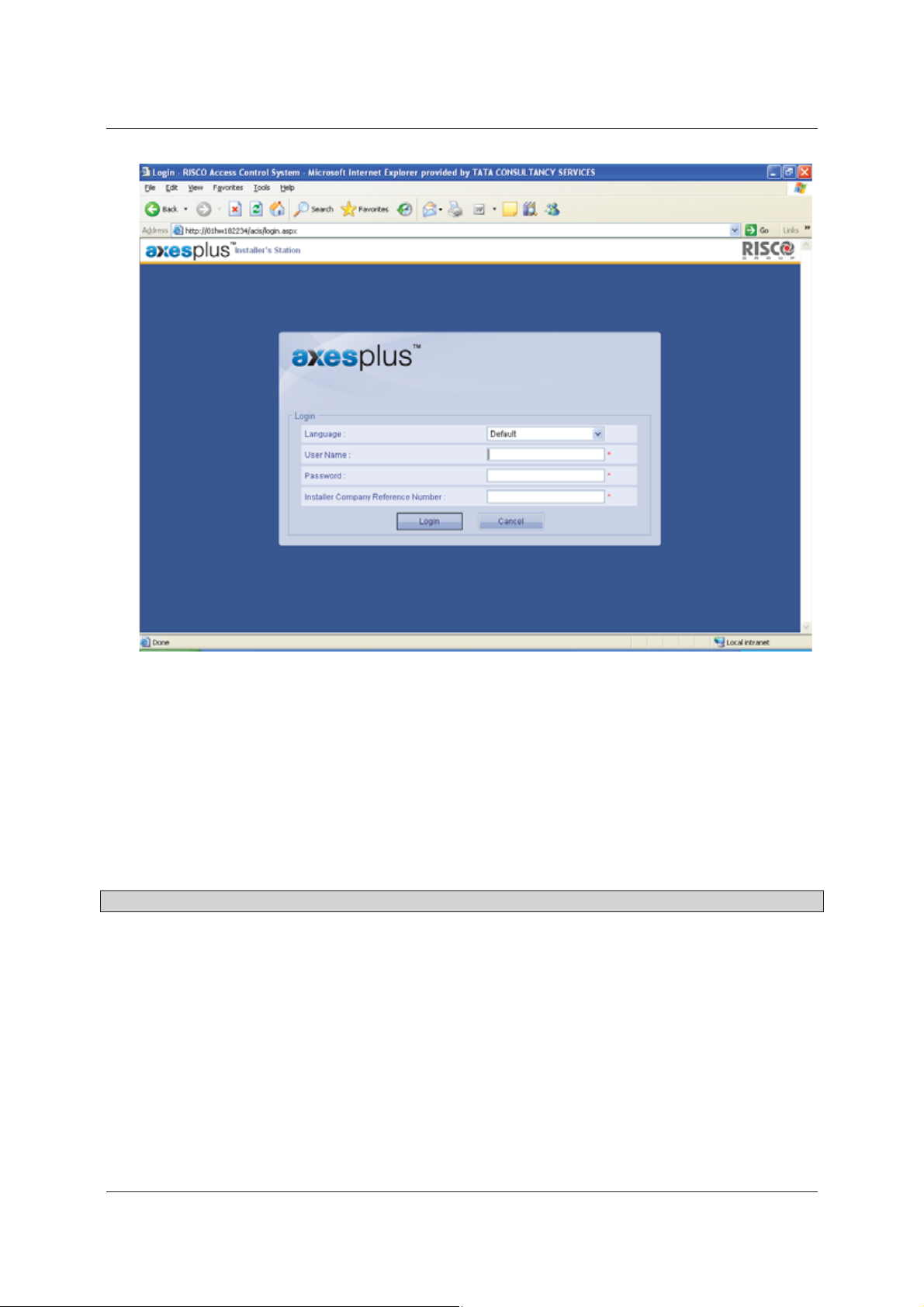
Figure 1: Login Screen
2. Select the language in which you want to be logged on to ACIS application from the Language drop-
down list. By default, Default language is selected. The languages available are:
• English
• French
• Italian
• Hebrew
Select any language and the labels and text on the user interface appears in the selected language.
Note: If you do not select any language, ACIS is displayed in the default language of the computer.
3. Enter the User Name and Password. When the operator creates a new account an assigns it to an installer
company, the main installer is created and the User Name, One Time Password (OTP) Device ID and
Company Reference ID is sent to the main installer by a system-generated email.
4. Enter the Installer Company Reference Number.
5. Click Login. The ACIS home page appears. When you logon to ACIS for the first time, only main section is
visible.
Uncontrolled when printed © RISCO Group 4
Page 14
User Manual for ACIS Version
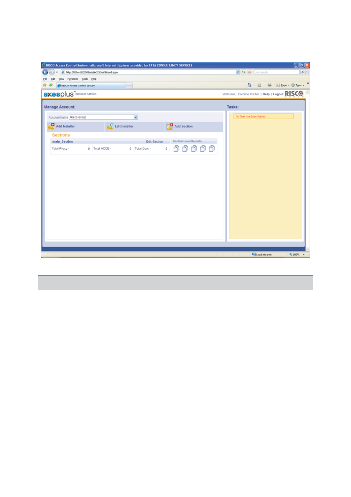
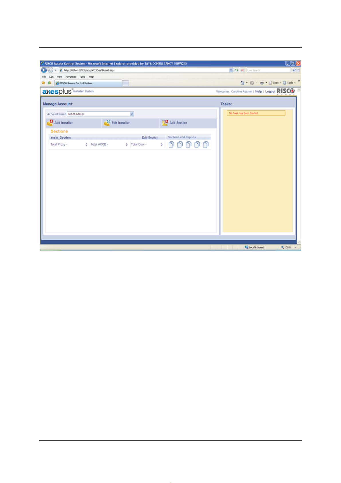
Figure 2: ACIS Home Page
Note: The fields marked with an asterisk (*) are mandatory. At any point in time, you can click Cancel to
exit the application.
The Account Name and sections to which you have access to are displayed on the screen. You can select any
other Account Name to which you have access to from the Account Name drop-down list.
After you register and configure devices for each section, the details such as the total number of proxies, ACCB’s
and doors in the section appear on the Manage Account dashboard under the particular section name. In
addition, if there are any disconnect proxies or controllers, the information in also displayed on the dashboard.
2.3 Logging Off from ACIS
Click the Logout link at the upper-left corner of the home page to log out from ACIS.
2.4 Overview of the Activities in ACIS
When you log on to ACIS, you need to perform the following tasks in order to start the RAC system:
1. Register Proxy
2. Configure Proxy
3. Register Controller
4. Configure Controller
Uncontrolled when printed © RISCO Group 5
Page 15

User Manual for ACIS Version
5. Configure Door
6. Perform Built-in Test for Proxy
7. Perform Built-in Test for Controller
After these tasks are performed, there are some generic tasks that you can do as per your requirement:
• Replace or Transfer Proxy
• Add Template Proxy
• Replace or Transfer Controller
• Add Template Controller
• Firmware Download
• Adding Locations
• Create Section
• Create and Edit Installer
• View Section Level Reports
The procedures to perform each of these tasks are explained below.
Uncontrolled when printed © RISCO Group 6
Page 16

User Manual for ACIS Version
3 Registering Proxy
You have to set up the firmware and then configure the firmware with the RSP. The devices that are setup are
Proxy, Controllers, ACIB, Relays, Sensors and Readers. Refer to the Glossary for the explanation of each of the
devices.
Each reader is connected to an Access Control Input-Output Board (ACIB). Up to four readers can be connected
to one ACIB. The ACIB is connected to the Access Control Controller board (ACCB) and up to two ACIB’s can be
connected to the board. ACCB stores the actual configurations. All the access decisions are taken by ACCB. ACCB
communicates with the Risco Service platform (RSP) through a Proxy. Proxy provides a communication channel
between the ACCB/ACIB and the RSP. This includes proxy to RSP (like events) and RSP to ACCB (configuration
updates) communication
Each section must have at least one primary proxy and can have one standby Proxy. The standby proxy serves as
a backup device in case of failure of the primary proxy, hence, it is recommended to have one stand by Proxy.
Each Proxy can have only one Stand by Proxy.
You have to register a proxy for a section and then only then it will be functional. In case the authentication of
users is through LDAP, then proxy will connect and authenticate through the onsite LDAP server, GSM, WN,
PSTN and other networks.
A proxy uses LAN/WAN first to communicate with the RSP Server. In case LAN/WAN is not available, then a proxy
will first connect to a dial-up (PSTN) connection and if that is not available, to a GSM connection.
You can perform the following actions:
• Register Proxy
• Add Template Proxy
• Transfer Proxy
• Replace Proxy
3.1 Register Proxy
Whenever you create a section, you need to register the proxy to it. For each section in the account, you can
have multiple proxies. Proxies need to be registered and assigned to the sections in order for them to
communicate with the RSP. When we select an account, all the sections in the account are displayed. Each
section displays the total number of proxies, controllers and doors assigned to the section. The number of
disconnected devices are displayed too.
To register Proxy:
1. Log on to ACIS. The home page appears.
Uncontrolled when printed © RISCO Group 7
Page 17
User Manual for ACIS Version
Figure 3: Active Proxies in a Section
2. Select the account from the Account Name drop-down list. As an installer, you may have access to
multiple accounts. Select the relevant account where you want to do configuration.
3. Click the Section Name to which you want to register a Proxy. For example, click Main_Section. The main
page for registering Proxies appears.
Uncontrolled when printed © RISCO Group 8
Page 18
User Manual for ACIS Version
Figure 4: Section Home Page
4. Click Register Proxy. The Register Proxy screen appears.
Note: The fields marked with an asterisk (*) are mandatory.
Uncontrolled when printed © RISCO Group 9
Page 19

User Manual for ACIS Version
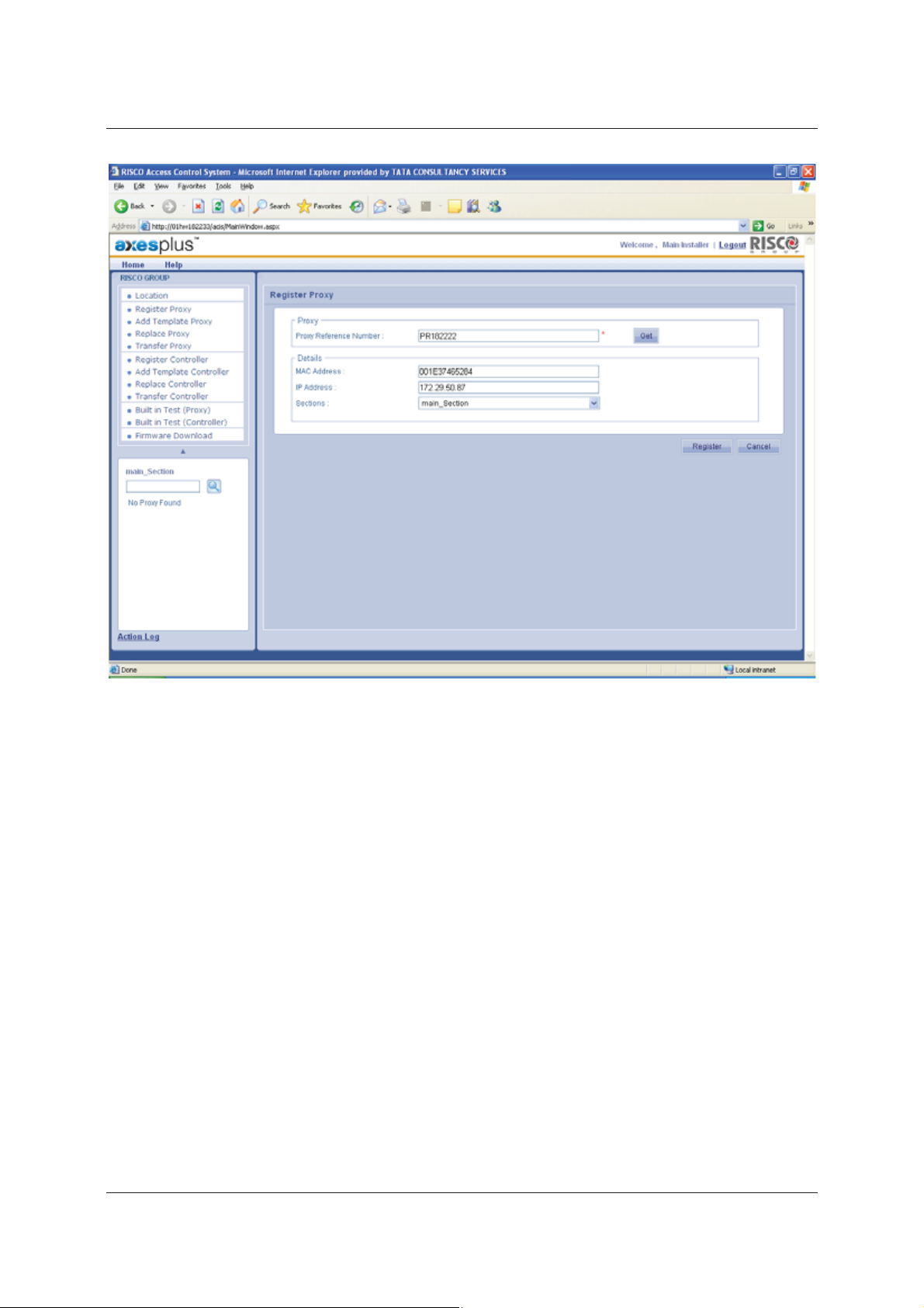
Figure 5: Register Proxy
5. Enter the Proxy Reference Number. The Proxy Reference Number is the unique identification number
written on each Proxy device.
6. Click Get. The MAC Address and the IP address of the Proxy are populated in the respective fields.
7. Select the Section to which you want to register this proxy from the drop-down list. This proxy is assigned
to the Main Section.
Uncontrolled when printed © RISCO Group 10
Page 20
User Manual for ACIS Version
Figure 6: Proxy Registration on entering all the values
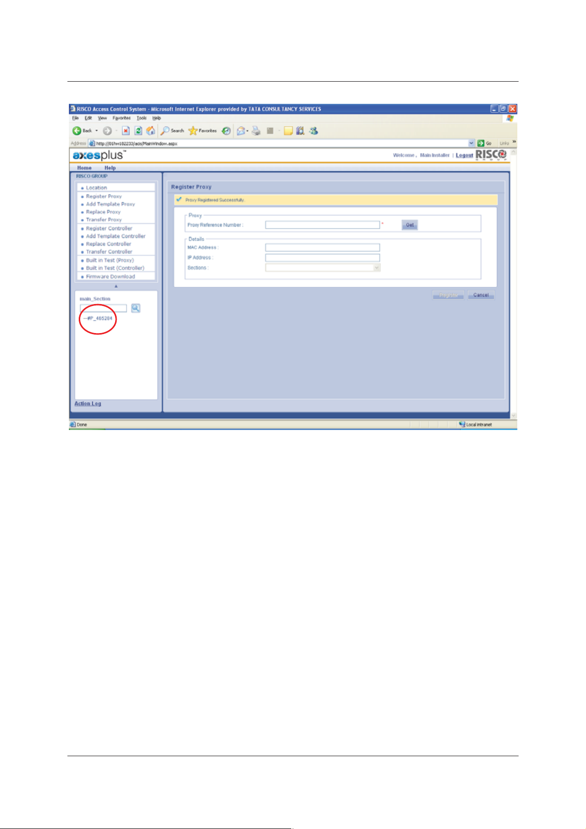
8. Click Register. The Proxy is registered for the selected section. The system displays a message, “Proxy
Registered Successfully”.
Uncontrolled when printed © RISCO Group 11
Page 21
User Manual for ACIS Version
Figure 7: Success message on Proxy Registration
After the successful registration, the Proxy Name appears in the Tree View in the bottom left corner of the
screen. The tree view displays all the Proxies, Controllers and Doors connected to the section. The registered
Proxy Name appears in the tree view.
After you register and configure devices for each section, the details such as the total number of proxies, ACCB’s
and doors in the section appear on the Manage Account dashboard under the particular section name.
After you register a proxy, you need to configure it.
3.2 Configure Proxy
To configure Proxy:
1. Click the Proxy Name that appears in the tree view. The Configure Proxy screen appears.
Uncontrolled when printed © RISCO Group 12
Page 22
User Manual for ACIS Version
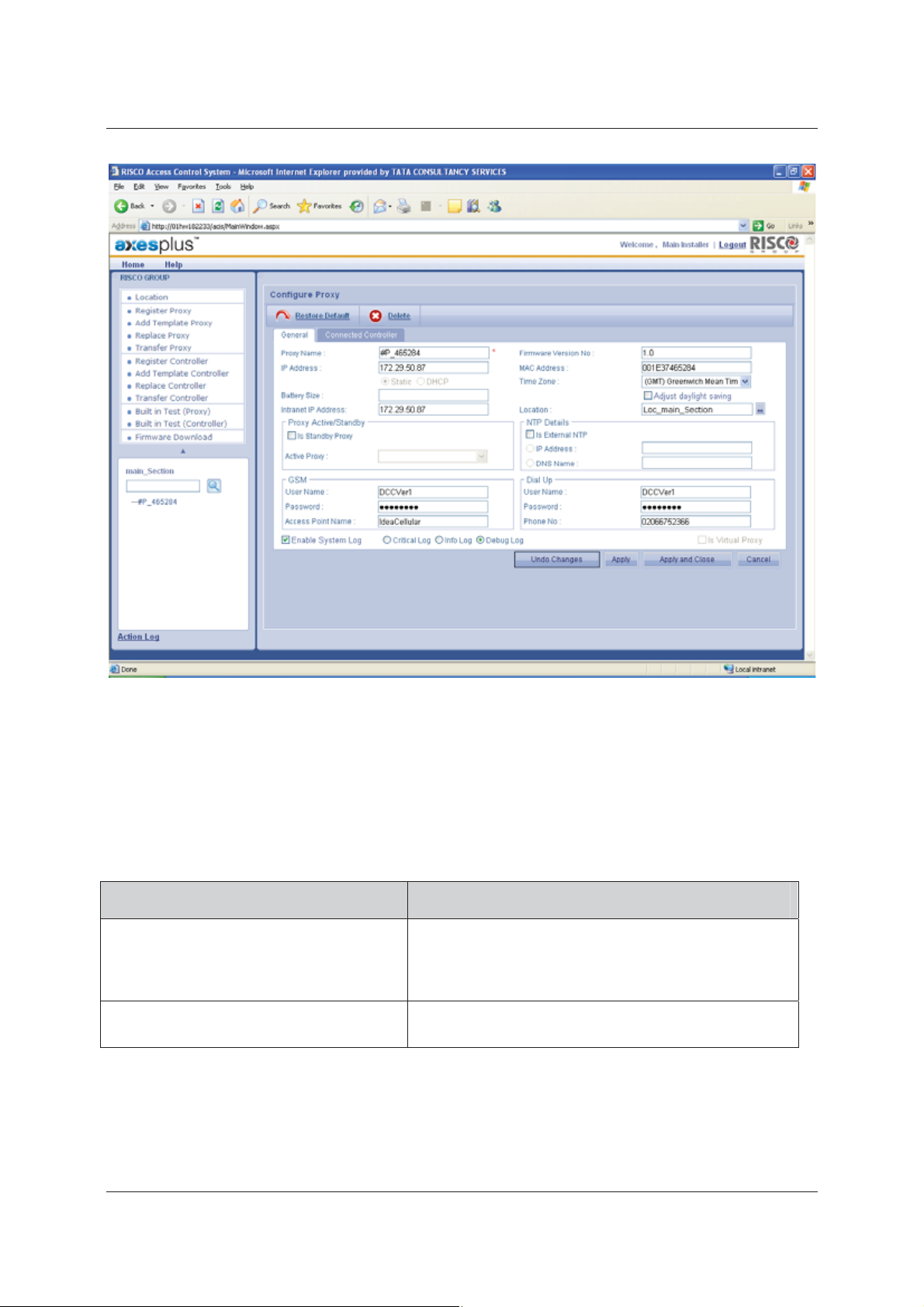
Figure 8: Configure Proxy
The Proxy Name, Firmware Version No., IP Address, MAC Address are displayed by default. IP Address and
MAC Address fields are non-editable. The Static and DHCP option buttons are read-only. The static function
makes the IP address constant. The IP is configured from the configuration file. If the DHCP option button is
selected, the proxy will extract the IP address from the DHCP Server.
2. Enter the following details in the fields:
Table 1: Configure Proxy
Field Name Description
Proxy Name
IP Address
Provide a name to the Proxy. This is the only mandatory
field on this screen. When you register Proxy, the Proxy
name is displayed in this field. You can change it if
necessary.
The IP address of the proxy is displayed. This is a read-only
field.
Uncontrolled when printed © RISCO Group 13
Page 23
Field Name Description
User Manual for ACIS Version
MAC Address
Battery Size
Time Zone
Intranet IP Address
Location
Static
DHCP
This is a read-only field.
In computer networking, a Media Access Control address
(MAC address) is a unique identifier assigned to most
network adapters or network interface cards (NICs) by the
manufacturer for identification and used in the Media
Access Control protocol sub layer.
When the device is running on battery, the percentage of
battery strength available is displayed in this field.
Select the time zone from the drop-down list. By default,
the Proxy time zone is that of the Section.
The Intranet IP address is displayed. This is a read-only field.
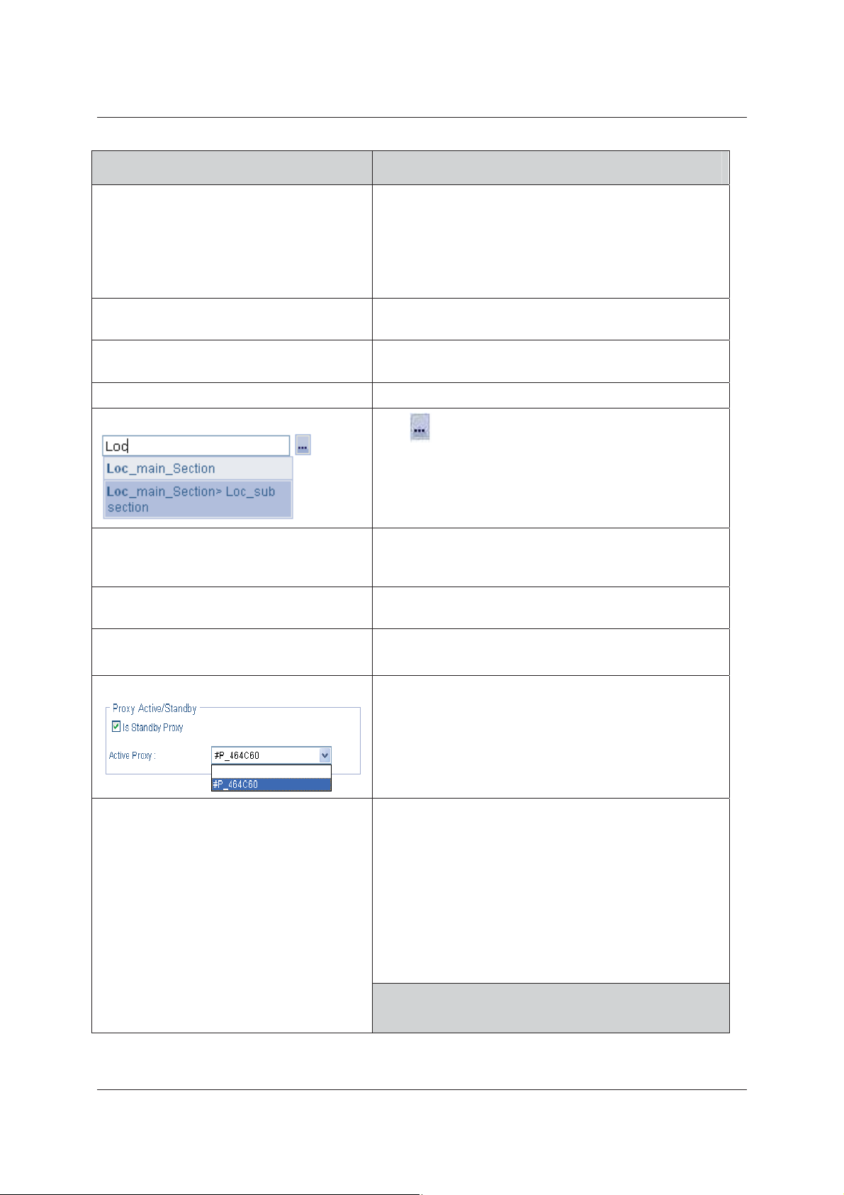
Click
a list of locations in the Account appears. Select a location.
The Location is auto-populated.
The Static and DHCP option buttons are read-only. The
static function makes the IP address constant. The IP is
configured from the CFG file.
If the DHCP option button is selected, the IP Address might
change every time the Proxy boots up.
to select the location. The Location window, with
Is Standby Proxy
Active Proxy
NTP Details
Select this check box to mark this proxy as a back-up proxy.
Select the active proxy with which you want to pair this
proxy as back-up from the drop-down list.
The Network Time Protocol (NTP) is used for automatic
time synchronization. NTP is for synchronizing the time
between the proxy and the server. It also synchronizes time
between ACCB’s.
name
Select the Is External NTP check box to enable and enter
the NTP details.
Click the IP Address or the DNS Name option button.
You can select only one option.
Note: In case you do not have an external NTP Server,
then the proxy will use DCC server as NTP
server. However, the NTP server service must
You need a valid NTP server IP / DNS
Uncontrolled when printed © RISCO Group 14
Page 24
Field Name Description
configured and running on the machine where
DCC is installed.
User Manual for ACIS Version
GSM
Dial Up
Proxy can use the Global System for Mobile
communications to communicate with the RSP server. To
do that, the GSM services need to be enabled.
The User Name, Password and Access Point Name are
reflected based on the configuration file. If the
configuration file has no data, then these fields will be
blank.
Enter the GSM details in these fields.
Note: When you enter the credentials, please ensure
that you have connected the GSM modem to the
proxy. Leave blank in case there you are not
using GSM modem.
Proxy can use the Dial up or Public Switched Telephone
Network (PSTN) to communicate with the RSP server
The User Name, Password and Access Point Name are
reflected based on the configuration file. If the
configuration file has no data, then these fields will be
blank.
Enter the Dial Up details in these fields.
Note: When you enter the credentials, please ensure
that you have connected the PSTN modem to the
proxy. Leave blank in case there you are not
using PSTN modem.
Enable System Log
Select this check box to enable system log for this proxy. By
default, the check box is enabled and the installer cannot
edit it, but can only select the type of log as required.
Note: There are three levels, Critical, Debug and Info.
Critical is enabled by default. If the user selects
Debug, then the debug info along with the critical
will be logged. If user selects Info, all three levels
of the messages will be logged.
3. Click Apply. The system displays a message, “Proxy configured successfully”.
or
• Click Apply and Close. The changes are reflected and the window is closed. The home page appears.
or
Uncontrolled when printed © RISCO Group 15
Page 25

User Manual for ACIS Version
• If you make changes and are unsure about it, click Undo Changes. The changes are not saved and all
the original details appear.
or
• Click Restore Default. The default configuration is done and all the changes are not saved.
Figure 9: Proxy Configured Successfully
You can click Cancel to close and return to the Home page.
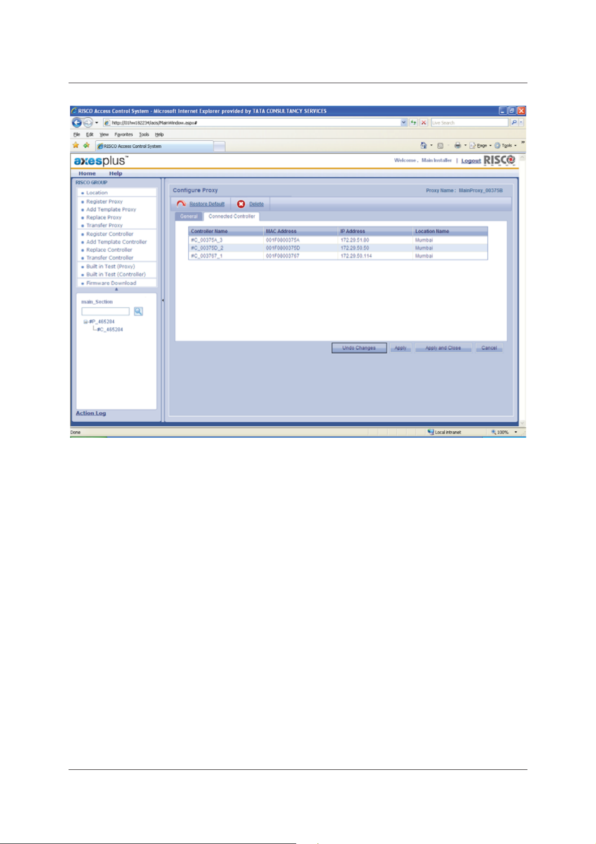
4. Click the Connected Controller tab. The list of controllers connected to the Proxy appears.
The screen displays the following details of the connected controller:
• Controller Name
• MAC Address - Unique ID for each device.
• IP Address
• Location Name
Uncontrolled when printed © RISCO Group 16
Page 26
User Manual for ACIS Version
Figure 10: Connected Controller
3.3 Delete Proxy
If we delete a Proxy with controllers which has a back up Proxy, then all the controllers are attached to the
backup proxy. It is not possible to restore a deleted Proxy, although it is possible to reboot the Proxy and register
it again.
To delete a Proxy:
1. Click the name of the Proxy in the tree view. The Configure Proxy screen appears.
Uncontrolled when printed © RISCO Group 17
Page 27
User Manual for ACIS Version
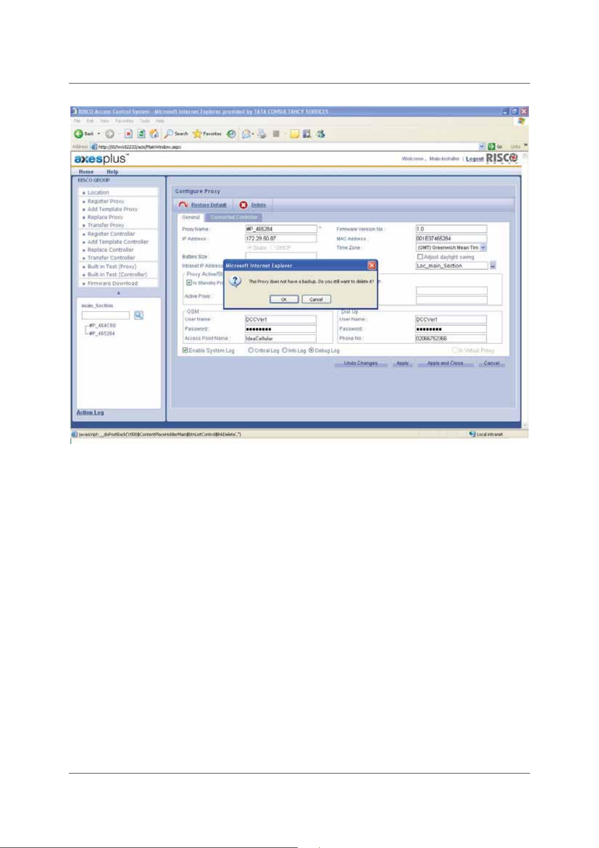
Figure 11: Deleting a Proxy
2. Click Delete, if there is a Standby proxy then the controllers attach themselves to the Standby proxy. If not,
then the system displays a message, “The Proxy does not have a backup. Do you still want to delete?”
3. Click OK. The Proxy is deleted.
3.4 Add a Template Proxy
A Template Proxy is added when there is no physical device present, but is expected to be available. You can
replace the Template Proxy by the Actual Proxy when the device is available. The configuration and the settings
done on the Template Proxy get applied to the replaced Proxy.
With the help of Template Proxy, you can configure the proxy before actually installing the hardware.
To add a Template Proxy:
1. Click Add Template Proxy. The Add Template Proxy screen appears.
Uncontrolled when printed © RISCO Group 18
Page 28
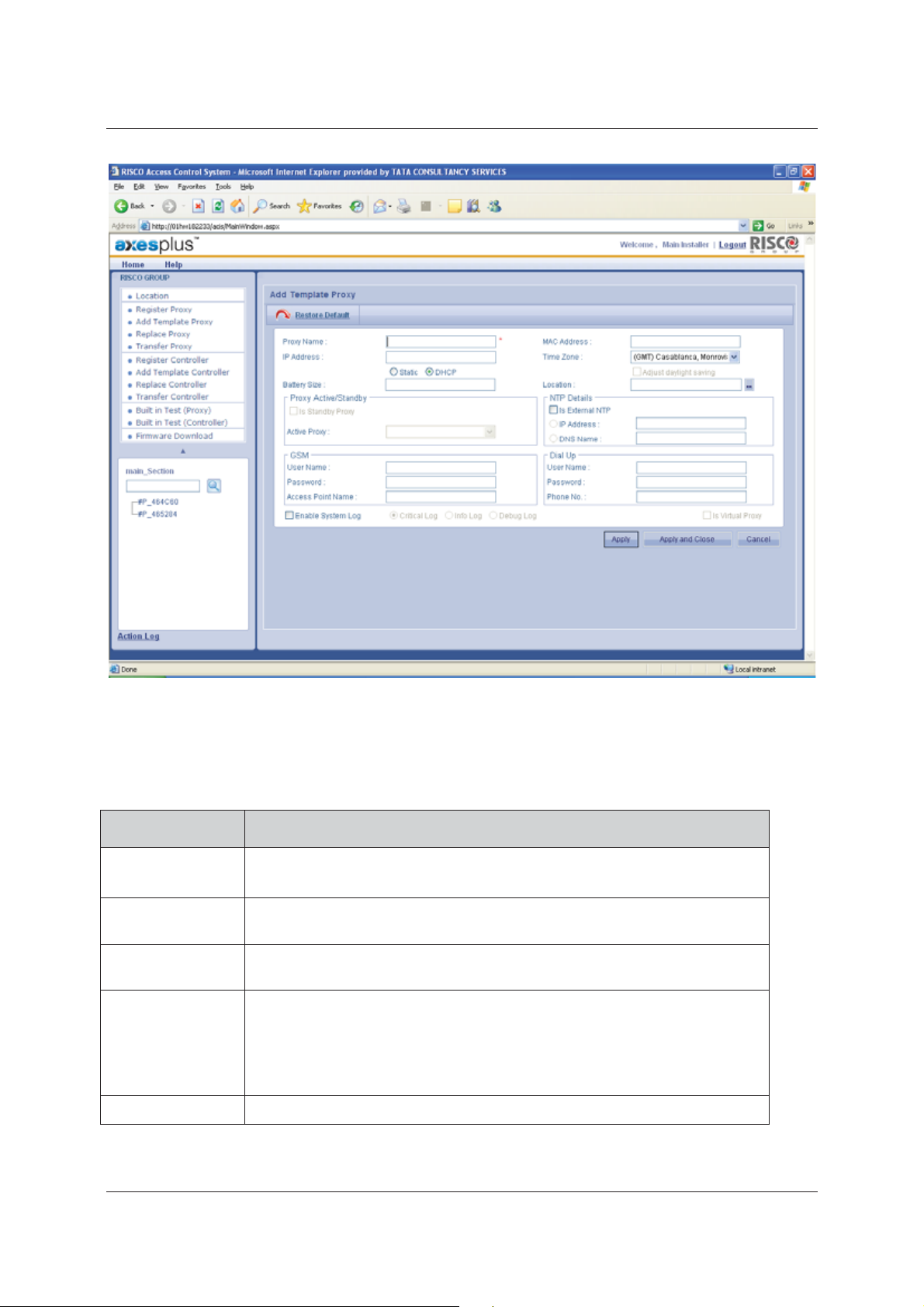
User Manual for ACIS Version
Figure 12: Adding a Template Proxy
2. Enter the details as per the following table.
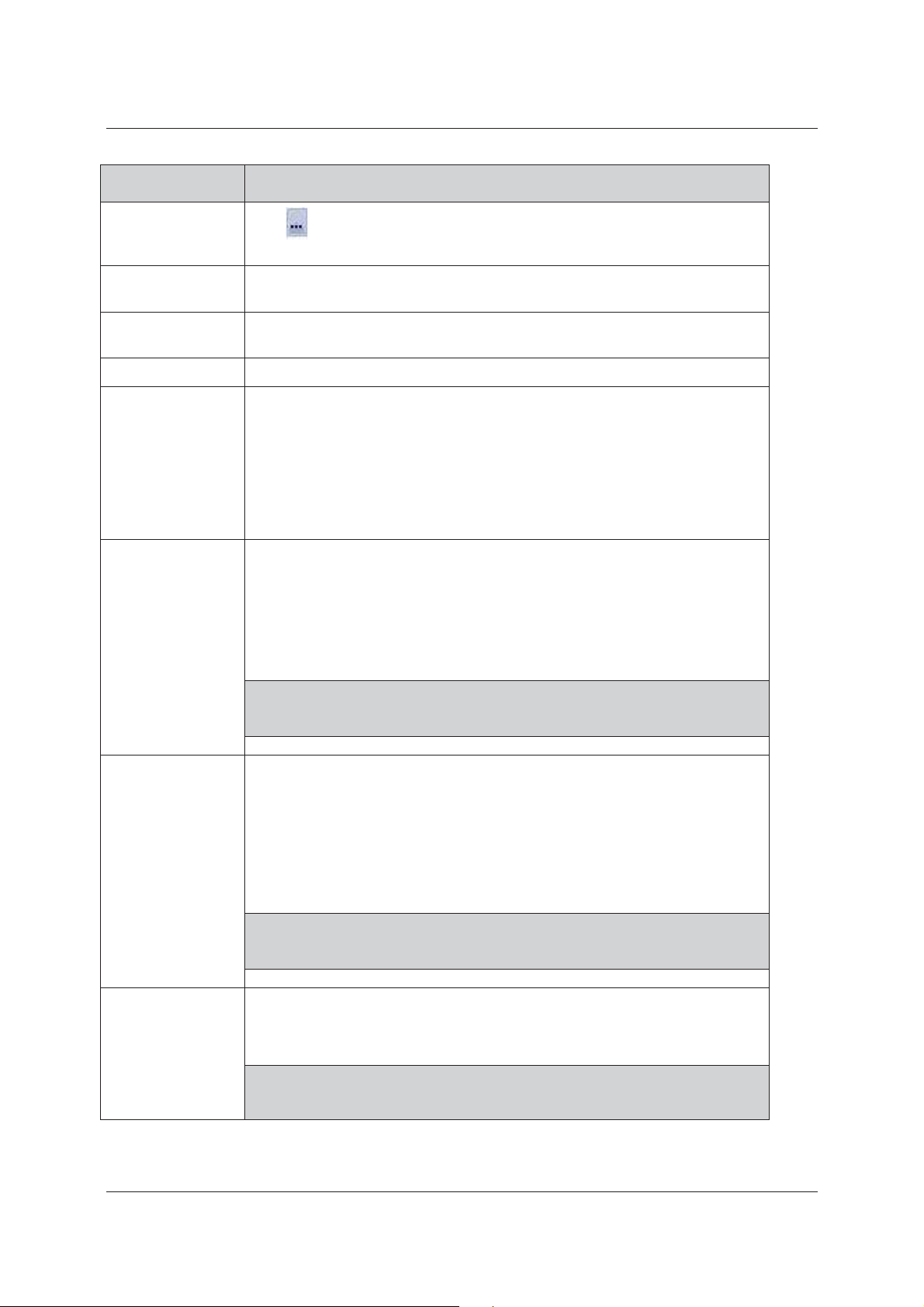
Table 2: Add Template Proxy
Field Name Description
Proxy Name
IP Address
Battery size
MAC Address
Time Zone
Provide a name to the Template Proxy.
This is the only mandatory field on this screen
Enter the IP Address of the Proxy. You also need to choose if the IP Address is of
the type Static or DHCP
When the device is running on battery, the percentage of battery strength
available is displayed in this field.
Provide the MAC Address.
In computer networking, a Media Access Control address (MAC address) is a
unique identifier assigned to most network adapters or network interface cards
(NICs) by the manufacturer for identification and used in the Media Access
Control protocol sub layer.
Select the time zone from the drop-down list
Uncontrolled when printed © RISCO Group 19
Page 29
Field Name Description
Location
Click
the Account appears. Select a location.
to select the location. The Location window, with a list of locations in
User Manual for ACIS Version
Static
DHCP
Active Proxy
NTP Details
GSM
The Static and DHP option buttons are read-only. The static function makes the
IP address constant. The IP is configured from the CFG file.
If the DHCP option button is selected, the IP Address might change every time
the Proxy boots up
You cannot configure Active Back-Up Pair for a Template Proxy
The Network Time Protocol (NTP) is used for automatic time synchronization.
NTP is for synchronizing the time between the proxy and the server. It also
synchronizes time between ACCB’s.
name
Select the Is External NTP check box to enable and enter the NTP details.
Click the IP Address or the DNS Name option button.
You can select only one option.
Proxy can use the Global System for Mobile communications to communicate
with the RSP server. To do that, the GSM services need to be enabled.
The User Name, Password and Access Point Name are reflected based on the
configuration file. If the configuration file has no data, then these fields will be
blank.
Enter the GSM details in these fields.
Note: When you enter the credentials, please ensure that you have
connected the GSM modem to the proxy. Leave blank in case there
you are not using GSM modem.
You need a valid NTP server IP / DNS
Dial Up
Enable System Log
Uncontrolled when printed © RISCO Group 20
Proxy can use the Dial up or Public Switched Telephone Network to
communicate with the RSP server
The User Name, Password and Access Point Name are reflected based on the
configuration file. If the configuration file has no data, then these fields will be
blank.
Enter the Dial Up details in these fields.
Note: When you enter the credentials, please ensure that you have
connected the PSTN modem to the proxy. Leave blank in case there
you are not using PSTN modem.
Select this check box to enable system log for this proxy. By default, the check
box is enabled and the installer cannot edit it, but can only select the type of log
as required.
Note: There are three levels, Critical, Debug and Info. Critical is enabled
by default. If the user selects Debug, then the debug info along with
the critical will be logged. If user selects Info, all three levels of the
Page 30
Field Name Description
messages will be logged.
User Manual for ACIS Version
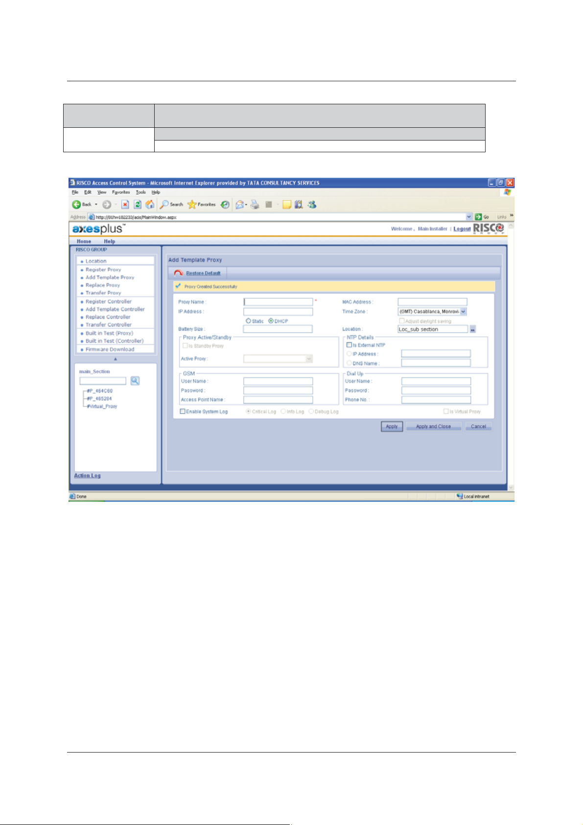
Figure 13: Template Proxy Created Successfully
3. Click Apply. The message appears, “Proxy Created Successfully”. The Proxy is visible on the tree view on
the bottom left corner of the screen.
Or
• Click Apply and Close. The Template Proxy is created and the window is closed. The home page appears.
You can create multiple Template Proxies for a given section.
3.5 Replace Proxy
If a proxy is malfunctioning, then you can replace the old Proxy with a new Proxy. In addition, when you create a
Template Proxy, you can replace the Template Proxy with the Actual Proxy. When a Proxy is replaced, all
configuration made to the earlier Proxy is transferred to the New Proxy by default. The old Proxy is deleted from
the system.
To replace the Proxy:
Uncontrolled when printed © RISCO Group 21
Page 31

1. Click Replace Proxy. The Replace Proxy screen appears.
User Manual for ACIS Version
Figure 14: Replacing a Proxy
2. Select the Proxy to be replaced from the Proxy Name to Replace drop-down list. The IP Address MAC
Address and the Location of the selected Proxy are displayed. The MAC Address, Proxy ID and IP address
are not replaced. The value is fetched from the device configuration.
3. In the New Proxy area, the registered Proxies are listed in the Proxy Reference Number drop-down list.
Select the Proxy that you want to replace the old Proxy with.
4. Click Get. The IP Address MAC Address and the Location of the selected Proxy are displayed. These are
read-only fields.
Uncontrolled when printed © RISCO Group 22
Page 32

User Manual for ACIS Version
Figure 15: Message on successfully replacing a Proxy
5. Click Replace. The old Proxy is replaced with the New Proxy. The system displays a message, “Proxy
Replaced Successfully”.
3.6 Transfer Proxy
You can transfer a Proxy in case the Proxy is connected to a wrong section. It is possible to transfer Proxies from
one section to another. However, if there controllers attached to the Proxy, and then it is not possible to transfer
the Proxy. After the transfer, the backup proxy (if available) of the transferred proxy becomes active. The old
proxy will continue to be active in the new section. Using ACIS, you can move the Proxy back to the previous
section.
You cannot transfer Template Proxies.
To transfer Proxy:
1. Click Transfer Proxy. The Transfer Proxies between Sections screen appears. The list of Proxies in the
Account is displayed.
Uncontrolled when printed © RISCO Group 23
Page 33

User Manual for ACIS Version
Figure 16:Transfer Proxy
2. Select and move the Proxies that you want from Proxies area to the Selected Proxies area.
3. Select the section in which you want to move the Proxy from the New Section drop-down list.
4. Click Transfer. The selected Proxies are moved to the new section. The message appears, “Proxy
Transferred Successfully”
Uncontrolled when printed © RISCO Group 24
Page 34

User Manual for ACIS Version
Figure 17: Proxy Transferred Successfully
5. Click Cancel to return to the home page.
3.7 View Action Log
In ACIS, whenever you perform any action, you can click the Action Log link available at the bottom-right of the
screen to view the process status. For example, if you have registered a proxy, a controller and configured doors;
performed built-in test for proxy and controller and you want to view the status of the actions, then:
1. Click Action Log. The following window displays the status of each of the activities performed in ACIS.
Uncontrolled when printed © RISCO Group 25
Page 35

User Manual for ACIS Version
Click Close to close the window.
Figure 18: Process Status
Uncontrolled when printed © RISCO Group 26
Page 36

User Manual for ACIS Version
4 Registering Controller
The Access Control Controller Board (ACCB) handles all access control logic in the RAC system. It can work
independently from the ACIS and the RSP servers. They supervise the Readers, as well as the Sensors and the
Relays related to the access control.
The ACCB has the following:
• Interface to two Access Control Input/Output board (ACIB)
• Interface to LAN network which connects it using a Proxy to the RSP Servers
• Programming storage and storage for historical events.
An ACCB is connected to the Access Control Input Output Board (ACIB). An ACCB can be connected to up to two
ACIB’s. Up to two doors can be connected to an ACIB. You can also attach a single to an ACIB. Each ACCB can be
connected to four doors, eight relays, eight sensors and four readers through ACIB’s. ACCB stores the actual
configurations. All the access decisions are taken by ACCB. ACCB communicates with RSP server through a Proxy.
You can perform the following actions:
• Register Controller
• Configure Controller
• Add Template Controller
• Transfer Controller
• Replace Controller
• Delete Controller
4.1 Register Controller
To register a controller, you need to search the controller based on its MAC address. You may also perform a
blank search which will display the available controllers with the details as MAC Address, IP Address, Proxy
Name, Section Name and Status.
To register a controller:
1. Click Register Controller. The Register Controller screen appears.
2. Enter the MAC address of the controller that you want to register and assign to the Proxy.
Or
3. Click Get. The list of controllers which are not registered, with the details such as the ACCB name, MAC
Address, IP Address, Proxy Name, Section Name and Status are displayed.
Uncontrolled when printed © RISCO Group 27
Page 37

User Manual for ACIS Version
Figure 19: Register Controller
4. Click the controller name option button.
Note: A controller uses the Proxy to register itself. If the controller has boot up from the correct proxy in
the correct section, then the Assign Proxy field is disabled. If the Assign Proxy field is enabled,
then it indicates that the controller is boot up from a proxy that belongs to some other section. In
such case, you need to assign it to the correct Proxy from the drop-down list.
Uncontrolled when printed © RISCO Group 28
Page 38

User Manual for ACIS Version
Figure 20: Controller Registration in Different Section
5. Click Register. The Controller is assigned to the Proxy and the system displays a message, “Controller
registered successfully”.
Note: You can click Discover Devices to get the list of all unidentified controllers attached to the Proxy in
the particular section.
Uncontrolled when printed © RISCO Group 29
Page 39

User Manual for ACIS Version
Figure 21: Controller Registered Successfully
The controller appears in the Tree view, under the selected Proxy.
4.1.1 Configure Controller
After the Controller is successfully created, you have to configure the controller the same way that Proxy was
configured.
To configure a controller:
1. Click the Controller Name under the Proxy in the tree view. The Configure Controller screen appears.
There are four tabs on the screen. The General tab is displayed.
Uncontrolled when printed © RISCO Group 30
Page 40

User Manual for ACIS Version
Figure 22: Configuring the Controller
2. Enter the details in the following fields.
Field Name Description
Controller Name
Time Zone
Proxy Name
Battery Size
IP Address
MAC Address
Static
Table 3: Configure Controller
The controller name appears when the controller is registered. You
can enter a new controller name if required.
Select the appropriate time zone. By default, controller will have the
time zone of the Proxy.
The name of the Proxy where the Controller is attached is displayed.
When the device is running on battery, the percentage of battery
strength available is displayed in this field.
The IP address of the Controller is displayed. This is a read-only field.
The MAC address of the Controller is displayed. This is a read-only
field.
The Static and DHP option buttons are read-only. The static function
makes the IP address constant. The IP is configured from the CFG file
Uncontrolled when printed © RISCO Group 31
Page 41

Field Name Description
User Manual for ACIS Version
DHP
Location
Is Virtual
Enable System Log
Air Lock
Firmware Version No.
If the DHCP option button is selected, the IP Address might change
every time the Proxy boots up.
Click
to select the location. The Location window, with a list of
locations in the Account appears. Select a location.
This field is disabled when you are registering a real controller.
Select this check box to enable system log for this controller. By
default, the check box is enabled and the installer cannot edit it, but
can only select the type of log as required.
Note: There are three levels, Critical, Debug and Info. Critical is
enabled by default. If the user selects Debug, then the
debug info along with the critical will be logged. If user
selects Info, all three levels of the messages will be
logged.
Air Lock will be enabled only when controller has more than one
door. When you select Air Lock check box, you can open only one
door at a time. For details, see Glossary.
The version number of the controller and ACIB is displayed. This is a
read-only field.
Doors
Each controller can be connected to maximum four doors. Select the
Doors check boxes to determine the number of doors connected to
the controller.
When you select the doors and click Apply. The door names appear
in the tree view under the controller. For example, if you select the
Door 1, Door 2, Door 3 and Door 4 check boxes, and click Apply, then
four doors appear under the controller in the tree view.
4.1.2 Configure Relay Details
When you create doors, the door type will be Door, not Turnstile. You can change the Door type from the Door
Configuration, later.
In this case, by default, Lock Relay 2 (Turnstile Relay) of the Door will be considered as External Relay and appear
on the Configure Controller screen, in the Relay Details tab.
To configure Relay Details:
Uncontrolled when printed © RISCO Group 32
Page 42

User Manual for ACIS Version
1. Click the Relay Details tab. The External Relays are displayed. The details such as the Relay ID, Relay Name
and Relay Mode are displayed. The name of the controller with whom relays are connected is also
displayed.
Figure 23: Relay Details
2. Click the Relay row that you want to configure.
3. Enter the following details on the screen.
Table 4: Configure Relay
Field Name Description
Relay ID
Relay Name
Location
Relay Status
Uncontrolled when printed © RISCO Group 33
The Relay ID is the unique identification number assigned
to the Relay. This is a read-only field.
The name assigned to the relay. You can change the name
as per your requirement.
Click
a list of locations in the Account appears. Select a location.
You can enable or disable relay as per your requirement.
to select the location. The Location window, with
Page 43

User Manual for ACIS Version
Field Name Description
Relay Mode
Pulse Duration
Activation Delay
You can change the Relay Mode. For details on Relay
mode, refer to Table 9: Relay Modes
By default, Pulse Duration is 10 seconds. You can change
the duration. The time duration for which the relay is in
the ON state.
The time duration for which the Relay will be off and
applied in continuous impulse
4.1.3 Configure Sensor Details
The external sensors, which are not connected to a door, are displayed.
To configure Sensor Details:
1. Click the Sensor Details tab. The external sensors appear. The Sensor ID and Sensor Name are displayed.
Uncontrolled when printed © RISCO Group 34
Page 44

User Manual for ACIS Version
Figure 24: Sensor Details
2. Select the Sensor row that you want to configure.
3. Enter the following details on the screen.
Table 5: Configure Sensor
Field Name Description
Sensor Name
Location
Rebound Delay
Send Events Select the Send Events check box to ensure that sensor sends an event to RSP
Enabled Click the Enabled option button to enable the sending events.
Normally Opened Select this check box if you want the status of the sensor to be Normally
The Sensor Name appears. You can change as per your requirement.
Click
the Account appears. Select a location.
It is the time taken by the output of the sensor to settle down and be functional
again. Longer the delay longer will be the response time of the sensor. The
default value is 60 seconds.
whenever there is a change in sensor status.
to select the location. The Location window, with a list of locations in
Uncontrolled when printed © RISCO Group 35
Page 45

User Manual for ACIS Version
Field Name Description
Opened.
When you select Normally Opened check box, then the sensor is inactive in
open state. When the sensor is closed, the status of the sensor becomes active.
4. Select the check boxes against the relays, which are available for the selected sensor. Whenever the sensor
becomes active, the selected relay (s) is turned on.
5. The relays available for the sensors differ according to the Sensor. For example, if you select the Sensor of
ACIB 1, then the relays of ACIB 1 appear.
4.1.4 Configure Reader Details
To configure Reader Details:
1. Click the Reader Details tab. The list of readers available for the controller appears.
Figure 25: Reader Details
2. Enter the following details in the fields.
Table 6: Configure Reader
Uncontrolled when printed © RISCO Group 36
Page 46

User Manual for ACIS Version
Field Name Description
Reader Name Click any reader to edit its properties. The reader name appears in the Reader
Name field. You may edit the reader name as per your requirement.
Reader
Technology
Assigned To Select the Door Side to which you want to assign this reader from the Assigned
Is Active Select the Is Active check box to make the reader active.
Is Connected Select the Is Connected check box if the reader is connected to the ACIB reader
Keypad Exists Select the Keypad Exists check box if the connected reader supports a keypad.
Select the Reader Technology from the drop-down list. Reader Technology is
type of the card or make of the reader used.
Note: The reader technologies that have an (A) symbol added to the name
are automatically recognised by the controller.
To drop-down list.
Maximum four readers can be connected to a single door.
port.
3. Click Apply. The message appears, “Controller Configured successfully”.
or
• Click Apply and Close. The changes are reflected and the window is closed. The home page appears.
or
• If you make changes and are unsure about it, click Undo Changes. The changes are not saved and all
the original details appear.
or
You can click Cancel to close and return to the Home page.
4.2 Door Configuration
You may configure door properties and properties of devices (relays and sensors) connected to the particular
door. You may also configure door related events.
4.2.1 Basic
You can edit configuration for a door.
Configure a door:
1. Click any Door in the tree view which you want to configure. The Door Details screen appears.
Uncontrolled when printed © RISCO Group 37
Page 47

User Manual for ACIS Version
Figure 26: Configuration of Basic Devices
2. In the Basic tab, enter the following in the fields.
Table 7: Configuration of Basic Devices
Field Name Description
Sequence Number
Door Name
Strike Delay
Reopening of the relay
This is the Door Sequence Number.
The Door Name appears by default when you select a Door from the tree view.
You may change the door name as per your requirement.
It is the time for which the door strike stays on when access is granted. If the door
does not open before the end of the door strike delay, it shall generate an event
declaring that the card was presented but the door was not opened if the user
has chosen to generate this event.
Enter the time in seconds. Default is 10 seconds
Select one of the options as mentioned below:
• At the End of Strike Delay
• As Soon As Door Closes
• As Soon As Door Opens.
Uncontrolled when printed © RISCO Group 38
Page 48

User Manual for ACIS Version
Door Type
Controller Name
Location
Door side 1 is
Relay Status Click Enabled or Disabled option button to enable or disable all relays
Door
There are two door types, door and turnstile. Select the door type as per your
requirement.
This is the controller to which the door is connected. This is a read-only field.
Click
Select whether the Door Side 1 is entry or exit from the options provided.
connected to the door.
By default, a door is enabled (the enabled check box is selected). To disable the
door, clear the check box.
and select the location from the list of locations.
4.2.2 Devices
For configuring relays and sensors connected to the door, perform the following steps:
1. Click the Device tab.
Figure 27: Configuration of Devices
2. Enter the following details in the fields:
Uncontrolled when printed © RISCO Group 39
Page 49

User Manual for ACIS Version
Table 8: Device Configuration
Field Name Description
Lock Relay 1 In the Relay Details area, the Lock Relay 1 will be used for the door lock of
a particular door.
Relay 1 will be the default relay for double door
Lock Relay shall have impulse type configuration with zero activation
delay and “door strike delay” pulse duration.
Lock Relay 2
Relay 2 will be for Turnstile door only (In turnstile, two relays are used that
is Relay 1 and Relay 2)
Lock Relay shall have impulse type configuration with zero activation
delay and “door strike delay” pulse duration.
Note: When the Lock Relay 2 check box is not selected, the relay will
considered external.
Door Open Too Long
Forced Door
Relay Mode
Activation Delay
Pulse Duration
Sensor 1: Door Sensor
Sensor 2: Conditional
Sensor
Sensor 3: Request to
Enter
When the door is open for duration more than what has been set in ACUS,
this relay will be triggered according to the relay mode. If the relay mode
is ‘Follows Sensor’ it will follow the door sensor. Door sensor should be
connected to the door physically.
If someone tries to break open into the door this relay is activated. Door
sensor should be connected to the door physically. If the relay mode is
‘Follows Sensor’ it will follow the door sensor.
You can select the Relay Mode for the relay. For details on Relay mode,
refer to Table 9: Relay Modes.
The time duration for which the Relay will be off and applied in
continuous impulse and impulse.
The time duration for which the relay is in the ON state.
A sensor which detects when a door is opened
The door sensor is connected to the IO board
It will give the open and closed state of door
Any type of sensor can be connected to the IO board. The decision to
grant access will depend upon the output of the sensor according to the
Door Configuration in ACUS.
A sensor that allows opening the door when it is in “Free access” mode. It
allows persons to enter without swiping cards at certain period of the day.
It is connected to the Free Access sensor/switch.
You can connect the request to enter sensor/switch to the IO board
Sensor 4: Request to Exit
Uncontrolled when printed © RISCO Group 40
A sensor that allows opening the door when it is in either in “Free Access”
or if the REX Schedule is valid.
It allows persons to enter without swiping cards at certain period of the
day
Page 50

User Manual for ACIS Version
It is connected to an REX sensor/switch.
The request to exit sensor/switch is connected to the IO board
Rebound Delay
Normally Opened
It is the time taken by the output of the sensor to settle down and be
functional again. Longer the delay longer will be the response time of the
sensor.
Select the check box to ensure that the normal status of the sensor is
open. If this is not selected then the normal status is closed.
3. Enter the following details in the fields:
Field Describe
Continuous Impulse
Figure 28
Table 9: Relay Modes
In this mode the Relay is in the ON state for the
duration as specified by Pulse duration and in the
OFF state for the period as specified by Activation
delay.
The mode can be set only for Custom Relays,
Forced Door relay and ‘Door Open Too Long’ relay
Default – Door Lock, Turnstile, Standard
<Explanation>
Continuous Toggle (1 sec. Pulse)
Uncontrolled when printed © RISCO Group 41
In this mode the Relay toggles in ON and OFF state
with a delay of one second between the two states.
The mode can be set only for Custom Relays,
Forced Door relay and ‘Door Open Too Long’ relay.
Page 51

User Manual for ACIS Version
Closed Until Reset
Follows Sensor
Figure 29
Impulse
30
In this state the Relay will be continuously in ON
state until an OFF command comes from ACCB or
DB server.
The mode can be set only for Custom Relays,
Forced Door relay and ‘Door Open Too Long’ relay
Default for door forced
The relay in this mode will follow the Sensor state
i.e. the relay will behave as per the details selected
in the Sensor Configuration
The mode can be set only for Custom Relays,
Forced Door relay and ‘Door Open Too Long’ relay
Default – Door Open too long
In this mode the relay will be in ON state for the
time duration as specified in Pulse duration. After
the time elapses it will switch to the OFF state.
The mode can be set only for Custom Relays,
Forced Door relay and ‘Door Open Too Long’ relay.
For Lock Relay 1 and Lock Relay 2 the default relay
mode will be Impulse and the ON time will be strike
delay(Pulse duration).
Toggle
Previous State Current State
ON OFF
OFF ON
In the Toggle mode if a command is received by
the Relay (from Server, ACCB) and the Relay is ON at
that point it will change the Relay State to OFF and
vice versa. It means it will toggle the sate of the
relay.
The mode can be set only for Custom Relays,
Forced Door relay and ‘Door Open Too Long’ relay
4. Make changes wherever you want and click Apply.
or
• Make changes and click Apply and Close. The changes are reflected and the window is closed. The
home page appears.
or
Uncontrolled when printed © RISCO Group 42
Page 52

User Manual for ACIS Version
• If you make changes and are unsure about it, click Undo Changes. The changes are not saved and all
the original details appear.
or
• Click Restore Default. The default configuration is done and all the changes are not saved.
You can click Cancel to close and return to the Home page.
4.2.3 Events
You configure the events that the door can generate in this tab.
1. Click the Events tab for configuring the Events. The list of Events that can be sent is displayed.
Figure 31: Events
2. Select the Send Events check box to ensure that the events provided in the list are generated.
3. Select the check boxes against the type of events that you want to view in ACUS. For example, if you select
the Door Open Too Long check box, then whenever this particular door will be open for a period greater
than configured, an event will be generated in ACUS.
4. The description of the events is given in the following table.
Uncontrolled when printed © RISCO Group 43
Page 53
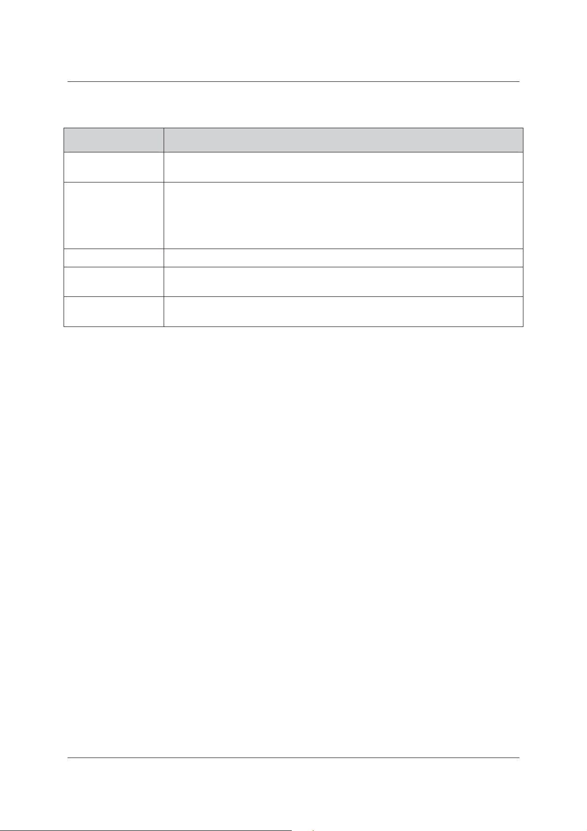
Table 10: Events Configuration
Field Name Description
User Manual for ACIS Version
Door Open/Close
Forced Door
Conditional Sensor
Door Open Too Long
Door not opened
after Access Granted
Select the check box if you want to generate an event when the door is opened or
closed.
If someone tries to break open into the door this relay is activated. Door sensor should
be connected to the door physically. If the relay mode is ‘Follows Sensor’ it will follow
the door sensor
Select the check box to generate an event if there is an intrusion and the door has been
forcibly opened.
Select the check box to generate an event when the conditional sensor is activated.
Select the check box to generate an event when a door is open for more than the time
specified in ACUS.
Select the check box to generate an event if the door is not opened within the strike
delay time.
5. Click Apply.
or
• Click Apply and Close. The changes are reflected and the window is closed. The home page appears.
or
• Click Undo Changes. The changes are not saved and all the original details appear.
or
You can click Cancel to return to the Home page.
4.3 Duplicate the Controller
The purpose is to create a duplicate of an existing controller. You can create another Template Controller with
the same configuration.
To duplicate a controller:
1. Click the Controller Name under the Proxy in the tree view. The Configure Controller screen appears.
2. Click Duplicate. The Controller Name dialog box appears.
Uncontrolled when printed © RISCO Group 44
Page 54

User Manual for ACIS Version
Figure 32: Duplicating Controller
3. Enter the Controller Name and click Apply. The controller is duplicated. The system displays a message,
“Duplicate Controller Created Successfully”. The Doors connected to the original controller are also
connected to the new controller.
4.4 Delete a Controller
You can delete a controller from the system.
To delete a controller:
1. Click the Controller Name under the Proxy in the tree view. The Configure Controller screen appears.
Uncontrolled when printed © RISCO Group 45
Page 55

User Manual for ACIS Version
Figure 33: Delete the Controller
2. Click Delete. The system displays a message, “Are you sure you want to delete this Controller?”
3. Click OK. The controller is deleted.
4.5 Add a Template Controller
A Template Controller is added when there is no physical device present, but is expected to be available. You
can replace the Template Controller by the Actual Controller when the device is available. The configuration and
the settings done on the Template Controller are applied to the replaced controller.
With the help of Template Controller, you can configure the controller before actually installing the hardware.
To add a Template Controller:
1. Click Add Template Controller. The Add Template Controller screen appears. There are four tabs on the
screen, General, Relay, Sensors, and Reader Details.
The General tab appears by default. You can enter the general details of the Template Controller in this tab.
4.5.1 General
To configure the general details of the controller:
Uncontrolled when printed © RISCO Group 46
Page 56

User Manual for ACIS Version
Figure 34: Add Template Controller
1. In the General tab, enter the details in the fields as per the following table:
Table 11: Add Template Controller
Field Name Description
Controller Name
Proxy Name
IP Address
Location
Enter the name of the controller as per your requirement.
Select the proxy to which you want to connect the controller from the
Proxy Name drop-down list.
Enter the IP Address of the Controller. You need to specify if it is a static IP
or DHCP IP.
Note: The IP of the Template Controller is just for your reference.
When you replace the Template with the actual controller it will
not affect the IP address of the actual device.
Click
. The list of locations for the selected section appears.
Uncontrolled when printed © RISCO Group 47
Page 57

User Manual for ACIS Version
Time Zone
Battery Size
MAC Address
Is Template Controller
Enable System Log
Air Lock
Select the required time zone from the drop-down field. Select the
Adjust Daylight Saving check box to adapt to the daylight saving
settings.
When the device is running on battery, the percentage of battery
strength available is displayed in this field.
Provide the MAC Address.
Note: The MAC address of the Template Controller is just for your
reference. When you replace the virtual with the actual
controller it will not affect the MAC address of the actual
device.
This field is disabled as you are creating a Template Controller.
If you wish to enable the system Logs, select the Enable System Log
check box. The Critical Log, Info Log, and option buttons are enabled.
Select the appropriate option button based on your requirements.
Air Lock will be enabled only when controller has more than one door.
When you select Air Lock check box, you can open only one door at a
time. For details, see Glossary.
Doors
Select the check boxes to create doors for Template Controller. The Doors
created are of type “Door”.
When you select the doors and click Apply. The door names appear in
the tree view under the controller. For example, if you select the Door 1,
Door 2, Door 3 and Door 4 check boxes, and click Apply, then four doors
appear under the controller in the tree view.
2. Select the Doors that you want to create. You can select one or more doors. For each ACIB, you can select
two doors. Each door has four relays.
Four doors can be connected to the ACIB. When you select the door, the readers are automatically populated.
The door name has to be in the <Door Name>_<Controller Name> format.
4.5.2 Relay Details
A relay is an electrical switch that opens and closes under the control of another electrical circuit and is a part of
ACIB. A relay is used to connect to external device:
• To open the door (Electric Lock)
• Connect to external devices like Alarms
1. Click the Relay Details tab. The already created Relays appear. By default, all Relay Names appear in the
Relay Sequence + Date Time String format. The Relay Number, Relay Name, and Relay Mode details for
all the relays appear.
Uncontrolled when printed © RISCO Group 48
Page 58

User Manual for ACIS Version
Note: The Relay Name has to be unique across the account. There cannot be two relays of the same
name.
Figure 35: Template Relays
2. The Relay name appears by default. You can change the Relay Name. The Relay Number is a read-only
field.
3. Click
4. Select the Relay Mode from the drop-down list as per your requirement. For details on relay modes, refer
to Table 9: Relay Modes
5. Enter the Pulse Duration for which the relay is in the ON state. By default, Pulse Duration is 10 seconds.
You can change the duration as per your requirement.
6. Enter the Activation Delay that is the time duration for which the Relay will be turned off and applied in
continuous impulse.
7. The relay is enabled by default. You may click Disabled to disable the relay.
4.5.3 Sensor Details
You can configure sensor properties from here. Sensors are part of the ACIB board.
1. Click Sensor Details tab. The Sensor ID and Name details appear.
and select the location from the list of locations. By default, all the relays are enabled.
Uncontrolled when printed © RISCO Group 49
Page 59

User Manual for ACIS Version
Figure 36: Template Sensor Details
2. You can change the name of the sensor. Note that this will be only for sensors not associated to a door
function and available for other use. The Sensor ID field is a read-only field.
3. Click
4. Enter the time you want to be taken by the output of the sensor to settle down and be functional again in
the Rebound Delay. Longer the delay longer will be the response time of the sensor.
5. Select the Send Events check box if you want to execute a macro using a keypad command. KP
commands are the commands for which the card has the authorization to enter a KP command to a
keypad which is attached to a door side on which the card is presented.
6. The sensor is enabled by default. You may click Disabled to disable the sensor.
7. Select the Normally Opened check box if the sensor is idle.
8. Select the check box against the relays displayed in the list to ensure that the relays are automatically
turned on when the Sensor is on. By default, all relays are selected for each sensor.
4.5.4 Readers Details
You can configure several types of readers from this tab.
1. Click the Reader Details tab. The readers are displayed according to the doors selected in the General tab.
and select the location from the list of locations.
Uncontrolled when printed © RISCO Group 50
Page 60

User Manual for ACIS Version
Figure 37: Template Readers
Maximum Four readers can be connected to one door. When you click the Reader tab, the reader details for the
selected doors appear.
1. Change the reader name as per your requirement.
2. Select the reader technology that you want from the Reader Technology drop-down list.
Uncontrolled when printed © RISCO Group 51
Page 61

User Manual for ACIS Version
Figure 38: Template Reader Technology Details
By default, Automatic is selected. You can change the reader technology as per your requirements. You can
configure the door side for every reader.
3. Select the door side to which the reader is assigned from the Assigned To: drop-down list.
Uncontrolled when printed © RISCO Group 52
Page 62

User Manual for ACIS Version
Figure 39: Template Reader Assign To Details
4. By default the Is Active and Is Connected check boxes are selected, which indicates that all readers are
active and connected to the doors.
5. Select the Keypad Exists check box if the reader requires a keypad.
6. You can use this function if you want to split the Card ID in minimum one or maximum three parts.
Depending upon the reader technology, you need to enter the start point in From Char field and length
of the characters that should appear in each window in the Over a length field. For example if your Card
ID is 0F034081B1, and you enter 1 in the From Char field and 3 in the Over a Length field, then the Card
ID which will be read by the reader will be 0F0.
7. Click Apply.
or
• Click Apply and Close. The message appears, “Controller created successfully”.
Uncontrolled when printed © RISCO Group 53
Page 63

User Manual for ACIS Version
Figure 40: Template Controller Created Successfully
You can click Cancel to close the screen and return to the home page.
4.6 Replace Controller
You can replace a controller when you want to use a new device with the existing configuration. You can also
create a Template Controller and replace with real controller as per your requirement.
To replace the controller:
1. Click Replace Controller. The Existing Controller tab appears.
Uncontrolled when printed © RISCO Group 54
Page 64

User Manual for ACIS Version
Figure 41: Replacing the Controller
2. Enter information in any of the fields (Controller Name, IP Address, Location, MAC Address, Door Name,
and Proxy Name)
3. Select the Virtual check box if you want to want to search actual and Template Controllers in this section.
4. Click Search. The actual and Template Controllers matching the specified criteria appear.
Note: You can click Reset to reset the fields.
Uncontrolled when printed © RISCO Group 55
Page 65

User Manual for ACIS Version
Figure 42: Search Results
5. Click the option button against the controller from the search results.
6. Click the New Controller tab.
Uncontrolled when printed © RISCO Group 56
Page 66

User Manual for ACIS Version
Figure 43: New Controller
7. Enter information in any of the fields (Controller Name, IP Address, Location, MAC Address, Door Name,
and Proxy Name)
8. Click Search. The existing controllers matching the specified criteria appear.
9. Select the controller to replace the existing one and click Replace. The selected controller in the Existing
Controller tab is replaced by this controller and the system displays a message, “Controller Replaced
Successfully”.
4.7 Transfer Controller
You can transfer controllers between the sections. You can transfer a controller only when the depending
entities are not used by any rules, automation and so on.
To transfer a controller:
1. Click Transfer Controller. The Transfer Controllers Between Sections dialog box appears.
Uncontrolled when printed © RISCO Group 57
Page 67

User Manual for ACIS Version
Figure 44: Transfer Controllers
2. Enter information in any of the fields (Controller Name, IP Address, Location, MAC Address, Door Name,
and Proxy Name)
3. Click Search. The existing and Template Controllers matching the specified criteria appear.
Uncontrolled when printed © RISCO Group 58
Page 68

User Manual for ACIS Version
Figure 45: Transfer Controller – Search Results
4. Select the section to which you want to transfer the controller from the Target Section drop-down list.
The Current Section name appears as per the current section by default.
5. Select the proxy to which you want to assign the controller from the Proxy drop-down list.
Uncontrolled when printed © RISCO Group 59
Page 69

User Manual for ACIS Version
Figure 46: Transfer to a Section
6. Click Transfer. The controller is transferred from the current section to the new section.
Uncontrolled when printed © RISCO Group 60
Page 70

User Manual for ACIS Version
5 Performing Built-In Test for Proxy
The Built-in test provides the diagnostic information about the proxy. You can also get a Log File of the proxy,
factory reset of the proxy, restart the Proxy and perform Built-in Test.
To get the information of the Proxy:
1. Click Built-in Test (Proxy). The Perform Built-in Proxy screen appears.
2. Enter the details in any of the fields and click Search. The Proxies in the particular section appear.
Figure 47: Built In Test – Proxy
Note: You can click reset to reset the field values.
3. Click the Proxy Name option button to select the Proxy.
4. Click Get Log File. The log for the selected Proxy appears on the same screen.
Uncontrolled when printed © RISCO Group 61
Page 71

Figure 48: Proxy Log
User Manual for ACIS Version
You can click
5. Click Restart. The Proxy is restarted.
6. Click Factory Reset. All configurations on the proxy are reset and the manufacturer’s default configuration
is restored. The Account ID will also be deleted, hence you need to insert the USB with the configuration
files in it to boot up the Proxy.
7. Click Perform Built-in-Test. The diagnostic report stating the overall health of the Proxy appears in the
same screen.
(Copy to Clipboard) to copy the log to clipboard and paste in notepad to get a better view.
Figure 49: Built-in Test Report
Uncontrolled when printed © RISCO Group 62
Page 72

User Manual for ACIS Version
The ACCB Connection information, Memory information, CPU Information, Virtual Memory Statistics, Stack
Memory, RAM Information, Flash Information, Active/Backup Proxy Connections and Hardware Information
about the Proxy is displayed.
Click
the information.
(Copy to Clipboard) to copy the log to clipboard and paste it in a notepad to get a better view of
Click Cancel to return to the Home Page.
Uncontrolled when printed © RISCO Group 63
Page 73

User Manual for ACIS Version
6 Performing Built-In Test for Controller
These are the initial tests that can be triggered to get a diagnostic report stating the overall health of the
Controller, the hardware status and so on.
To perform built-in test for Controller:
1. Click Built- in Test (Controller).
2. Enter the details in any of the fields and click Search. The Controllers in the particular section appear.
Figure 50: Built in Test - Controller
3. Click the Controllers Name option button to select the Controllers.
4. Click Get Log File. The log for the selected Controllers appears.
Figure 51: Controller Log
You can click
better view.
Uncontrolled when printed © RISCO Group 64
(Copy to Clipboard) to copy the log to clipboard and paste in notepad to get a
Page 74

User Manual for ACIS Version
5. Click Restart. The message appears.
Figure 52: Restart Message
6. Click OK. The message appears, “Restart command sent to device”.
7. Click Factory Reset. All configurations on the Controllers are reset and the manufacturer’s default
configuration is restored.
8. Click Perform Built-in-Test. The diagnostic report stating the overall health of the controller appears.
Figure 53: Built in Test Report
The Memory information, CPU Information, Virtual Memory Statistics, Stack Memory, RAM Information, Flash
Information, Active/Backup Proxy Connections, Access Authorisation Data Count, ACIB Communication Status
and Hardware Information about the Controller is displayed.
Click
the information.
Click Cancel to return to the Home Page.
Uncontrolled when printed © RISCO Group 65
(Copy to Clipboard) to copy the log to clipboard and paste it in a notepad to get a better view of
Page 75

User Manual for ACIS Version
7 Downloading Firmware
You can use this to upgrade the firmware version of the Proxy, Controller and ACIB.
7.1 Upgrade Proxy
To upgrade firmware for Proxy:
1. Click Firmware Download. The Firmware Download screen appears. The list of proxies connected to the
selected section is displayed.
Figure 54: Firmware Download
2. Select the Proxies for which you want to upgrade the firmware and move them to the Selected proxies
area.
3. Select the Firmware version number from the Proxy Firmware Version No. drop-down list.
Uncontrolled when printed © RISCO Group 66
Page 76

User Manual for ACIS Version
Figure 55: Proxy Firmware Downloaded Successfully
4. Click Upgrade. The firmware version upgrade for the proxy is initialized. The system displays a message,
“Firmware version Download message sent to device successfully”.
You can view the progress on the main dashboard, under the Tasks area on the ACIS dashboard.
7.2 Upgrade Controller
You can upgrade the firmware version for the controller in the similar manner as with the proxy.
To upgrade the Controller firmware version:
1. Click the Controller tab.
2. Click Search. The list of controllers in the particular section appears.
Uncontrolled when printed © RISCO Group 67
Page 77

User Manual for ACIS Version
Figure 56: Upgrading Firmware of the Controller
3. Select the check box against the Controller that you want to upgrade.
4. Select the new controller version from the Controller drop-down list.
5. Click Upgrade. The Controller version is upgraded. The system displays a message, “Firmware version
download Request has been sent to devices successfully. Please check Task List on dashboard for
status”.
Uncontrolled when printed © RISCO Group 68
Page 78

User Manual for ACIS Version
Figure 57: Controller Upgraded Successfully
6. Select the ACIB firmware version from the drop-down list.
7. Click Upgrade. The system displays a message, “Firmware version Download message sent to device
successfully”.
Uncontrolled when printed © RISCO Group 69
Page 79

User Manual for ACIS Version
Figure 58: ACIB Firmware Upgrade Successfully
7.3 Tasks
Whenever Firmware Upgrade is done, you can view the status of the upgrade on the home page.
Uncontrolled when printed © RISCO Group 70
Page 80

User Manual for ACIS Version
Figure 59: Firmware Upgrade Status
The Controller Names under the Tasks areas on the Home Page indicate the status of the firmware download.
You may click
Note: Normally, upgrading firmware would take maximum 4 minutes to 5 minutes. If the status on the
(Delete Tasks) to clear all pending tasks from the dashboard.
dashboard keeps on showing pending (device name still appears in red), then you need to restart
the device.
Uncontrolled when printed © RISCO Group 71
Page 81

User Manual for ACIS Version
8 Adding a Location
You may add as many locations in the section as required. From ACIS, you may add, delete and rename the
locations. This list will be generated in ACUS.
8.1 Add a Location
To add a location:
1. On the ACIS home page, click the section name where you want to add more locations.
Figure 60: Section Home Page
2. On the Section home page, click Location. The Location window appears.
Uncontrolled when printed © RISCO Group 72
Page 82

Figure 61: Location
User Manual for ACIS Version
3. Select any location, right-click and click Add. The Location Name dialog box appears.
Figure 62: Add Location Name
4. Enter the name of the location as per your requirement.
5. Click Apply. The location is added to the parent location and the message appears, “Location added
successfully”.
8.2 Rename a Location
To rename a location:
1. On the Section home page, click Location. The Location window appears.
2. Select any location, right-click and click Rename. The Location Name dialog box appears.
Uncontrolled when printed © RISCO Group 73
Page 83

User Manual for ACIS Version
Figure 63: Rename Location Name
3. Re-enter the name of the location as per your requirement.
4. Click Apply. The location is renamed and the message appears, “Location added successfully”.
8.3 Delete a Location
To delete a location:
1. On the Section home page, click Location. The Location window appears.
2. Select any location, right-click and click Delete. The following message appears.
Figure 64: Delete Location
3. Click OK. The message appears, “Location deleted successfully”.
Uncontrolled when printed © RISCO Group 74
Page 84

User Manual for ACIS Version
9 Adding a Section
Sections are partitioning entities that divide the account into logical configuration areas. Section is a part of the
access control system. It comprises physical entities (ACPE’s) and configuration entities (ACCE’s). Sections are
unique. The logged on section always belongs to the account to which you have logged on. When an account is
created in ACOS, the main section is created. This section cannot be deleted. You can add or delete other
sections.
9.1 Add Section
To add a new section:
1. On the ACIS home page, click Add Section. The Add Section dialog box appears.
Figure 65: Adding a New Section
Note: the fields marked with an asterisk (*) are mandatory. In the user interface, the ACCB is referred to
as the Controller.
2. Enter the following details on the Add Section screen:
Uncontrolled when printed © RISCO Group 75
Page 85

Table 12: Add a Section
Field Name Procedure
User Manual for ACIS Version
Section Name
HW Communication
Interval
Default language
User Update Interval
Installer Company Name
Installer Update Interval
Location
Is KeyFree Section
Is Main Section
Enter the name of the Section that you want.
The interval time is for semi-permanent connection. Enter the time in seconds.
Proxy drops the connection to RSP in case it is idle in this interval and then
would immediately reconnect again. This interval is used for load balancing at
RSP server. Defaults to 10 minutes. Minimum is one minute and maximum is 10
minutes.
Select the default language for the section.
RSP will send the application data to hardware after this time interval. Enter the
interval time minutes. It defaults to minimum one minute and maximum 60
minutes.
The installer company name appears by default.
RSP will send the application data to hardware after this time interval. Enter the
interval time in seconds. Defaults to 1 minutes and maximum is 60 minutes.
Enter the name of the main location to be created for the section. This is a
mandatory field
Select this check box to mark the current section as a KeyFree Section. This
section will be used to move data from Risco Group’s existing KeyFree system
to RSP system. This would be an identifier for identifying the section meant for
transferring data from KeyFree System.
This check box is only visible when you are editing the main section. This is an
identifier for identifying the Main Section. For all the sub-sections, this check
box will not be visible.
R/W Card Validity
The “end of validity” of card content for read/write card. Enter the interval time
in minutes This is the maximum time available for the user to swipe the card on
a Read/Write Reader. Defaults to 1440 minutes. After this time expires the
reader does not allow access to the card.
Default Time Zone
A drop-down field populated with a list of predefined time zones across the
world. Select the required time zone.
This is a Section level time zone. Devices can have their own time zones.
Adjust Daylight Saving
Select this check box to adjust day light saving as per the Time Zone selected (if
the country practices day light saving).
Logging
The errors at runtime are logged for reference. This is useful for RISCO during
the maintenance activity.
Select the Enabled check box to enable logging. If you enable logging, you can
log the errors either in Database or in Windows NT.
Select either the Database or Windows NT check box depending upon where
you want to enable logging.
LDAP Server
This is used for authentication of the user. Whenever a user logs on to ACUS,
the RSP sends request to LDAP server for authentication with Installers login
credentials. Refer to 9.1.1 LDAP Server Configuration for details about the
LDAP.
Uncontrolled when printed © RISCO Group 76
Page 86

User Manual for ACIS Version
LDAP Server Name
IP Address
Port Number
Enter the LDAP Server name.
Enter the IP address of the Server.
Enter the port number.
3. Click Save. The new section is created and the message, “Section created successfully” appears. The
home page appears with the section details displayed on the home page.
Note: If you click Cancel, the section is not saved and the home page appears.
The newly created section appears on the home page with the ACPE details. You can edit the section.
Figure 66: New Section Created
9.1.1 LDAP Server Configuration
The Lightweight Directory Access Protocol or LDAP is an application protocol for querying and modifying
directory services running over TCP/IP. This authentication mechanism can be used in ACIS and ACUS.
The LDAP protocol defines operations that clients use to search and update the directory. Whenever an installer
logs on to ACIS, the RSP sends request to LDAP server for authentication with Installers login credentials. The
users of RSP system can be authenticated using a LDAP server through the Proxy on the client’s LAN.
Uncontrolled when printed © RISCO Group 77
Page 87

User Manual for ACIS Version
9.2 Edit Section
To modify/edit the section details:
1. Click the Edit hyperlink next to the Section Name. The Configure Section screen appears.
Figure 67: Configure a Section
Uncontrolled when printed © RISCO Group 78
Page 88

User Manual for ACIS Version
2. Make changes wherever you want and click Apply. The message appears, “Section updated successfully”.
The home page appears with the edited section.
Note: If you click Undo Changes, the system reverts to all the details before any changes were made to
the section. If you click Cancel, the edited changes are not saved and the home page appears.
Click to delete the section.
Uncontrolled when printed © RISCO Group 79
Page 89

User Manual for ACIS Version
10 Adding and Editing an Installer Profile
When the operator creates the account, an installer company is created. When an installer company is created,
the main installer is also created. The main installer has the rights to create other installers. The main installer
cannot be deleted from the system. The main installer can log on to ACIS to create new installers.
10.1 Add an Installer Profile
The main installer creates other installers. The other installers can also create installers and assign sections to
them. However, the installer can only assign sections to the new installer to which he has access and can only
edit those installers that he has created.
To add an installer:
1. Click Add Installer on the home page. The Add Installer dialog box appears. There are two sections on
the window.
Figure 68: Adding an Installer
Note: The fields marked with an asterisk (*) are mandatory. If you click Restore Default, the default
entries appear and the new changes are not reflected.
In the Basics area, enter the following details:
2. Enter the Login ID. The login ID is a unique number and an alphanumeric field. The minimum length is 5
characters and the maximum is 30 characters. There can be no spaces in the login ID. If you try to assign a
Uncontrolled when printed © RISCO Group 80
Page 90

User Manual for ACIS Version
previously existing login ID, then the system displays an error message, “Login ID already exists. Please
select another Login ID”
3. Enter the Last Name, Middle Name and the First Name of the installer that you want to create. The
maximum length of this field is 50 characters.
4. Enter the OTP Device ID.
5. Enter the Phone number and Address.
6. Select the language from the Language drop-down list. The language selected for the installer becomes
the default language when the new user logs on to ACIS.
7. The installer company name is a read-only field. This has been created in ACOS when the account was
created.
The main installer will assign sections to the new installer. To assign sections:
8. In the Sections area, click the Section which you want to assign to the installer.
9. Click
installer.
Note: You can use the arrow to assign sections to the installer. You can add all the sections in the
area to the installer using the arrow. You can also remove all the assigned sections using the
10. Click Create, The installer is created and the sections are assigned to the new installer, the system displays
a message, “Installer created”.
and move the section to the Assigned Sections area. You can assign multiple sections to an
arrow or remove one by one using the arrow.
Uncontrolled when printed © RISCO Group 81
Page 91

User Manual for ACIS Version
Figure 69: Installer Created
You can click Cancel to return to the home page. In this case, the data that has been entered will not be saved.
When the installer will logon to ACIS, only the sections assigned to the installer will be visible. For example, if you
created an installer; assigned only DLF and Quadra sections, then when the installer log on to ACIS, the following
home page appears.
Uncontrolled when printed © RISCO Group 82
Page 92

User Manual for ACIS Version
Figure 70: ACIS Home Page for New Installer
10.2 Edit Installer Profile
Installers can create several installers. However, an installer can edit only those installers that have been created
by him. The installer can only assign those sections to which the installer has access.
To edit an installer:
1. Click Edit Installer on the home page. The Search Installer page appears.
2. Enter the search criteria and click
installer appear.
(Search). The list of all the installers created by the logged on
Uncontrolled when printed © RISCO Group 83
Page 93

User Manual for ACIS Version
Figure 71: Search an installer
3. Click the <Installer Name> which you want to edit. The Installer details appear.
Uncontrolled when printed © RISCO Group 84
Page 94

User Manual for ACIS Version
Figure 72: Configuring an Installer
4. Make changes wherever required and click Apply. The system displays a message, “Installer Updated”
Note: You can click Undo Changes to reflect the earlier details made prior to editing. If you click Apply
and Close, the installer is updated and the system closes the window. You can click Cancel to
cancel the edits and go to the home page. Click to delete the installer.
Uncontrolled when printed © RISCO Group 85
Page 95

User Manual for ACIS Version
11 Generating Section Level Reports
On the Manage Account Dashboard, you can view six types of Reports generated for a given section:
• As Built
• Proxy Configuration
• Controller Configuration
• Door Configuration
• System Parameters
Figure 73: Section Level Reports
11.1 As Built Report
1. Click the As Built report from the Section Level Reports area.
The As Built report displays the data pertaining to Proxy, MAC Address, IP Address, and Door Configuration
Details against a given section.
Uncontrolled when printed © RISCO Group 86
Page 96

User Manual for ACIS Version
Figure 74:As Built Report
Door Details are displayed in the following table:
Uncontrolled when printed © RISCO Group 87
Page 97

User Manual for ACIS Version
Figure 75: Door Details
11.2 Proxy Configuration
The details of the proxy configuration that is the Proxy Name, MAC Address, NTP details and GSM details will be
displayed in this report.
1. Click the Proxy Configuration report from the Section Level Reports area.
Uncontrolled when printed © RISCO Group 88
Page 98

User Manual for ACIS Version
The fields displayed are:
• Proxy Name
• MAC Address
• Firmware Version Number
• Time Zone
• IP Address
• Location
• Status
• NTP IP Address
• NTP DNS Name
• GSM User Name
• GSM Password
• GSM Access Point name
• Dial Up User Name
Figure 76: Proxy Configuration Report
• Dial Up Password
Uncontrolled when printed © RISCO Group 89
Page 99

User Manual for ACIS Version
11.3 Controller Configuration
The Controller Configuration Report displays the reports on the various attributes of a controller namely its
name, MAC Address, Versions and so on as displayed in the following figure.
1. Click the Controller Configuration report from the Section Level Reports area.
Figure 77: ACCB Configuration Report
The following details are displayed:
• Controller
• IP Address
• MAC Address
• Proxy Name
• Location
• Time Zone
• Battery Size
• Relay Name
• Relay Type
Uncontrolled when printed © RISCO Group 90
Page 100

• Relay Mode
• Relay Pulse Duration
• Relay Activation delay
• Sensor Name
• Sensor Type
• Rebound delay
• Reader Name
• Reader Technology
• Reader Assigned to
• Read from Char - Window1
• Read over length - Window1
• Read from Char - Window2
• Read over length - Window2
• Read from Char - Window3
• Read over length- Window3
User Manual for ACIS Version
11.4 Door Configuration
The Door configuration is a consolidated report on the Door with all the technical configuration details. The
following figure displays the report.
Uncontrolled when printed © RISCO Group 91
 Loading...