

Riello UPS Master HE, Master HE 200 kVA, Master HE 100 kVA, Master HE 160 kVA, Master HE 120 kVA Technical Specifications
...Page 1
Technical specifications
Master HE
100/250 kVA THREEPHASE/THREEPHASE
On Line Double Conversion Technology (VFI)
Page 2

MASTER HE
SPTMHEE3T16FREN
1
INDEX
1. PURPOSE ......................................................................................................................................... 2
2. SYSTEM DESCRIPTION .................................................................................................................. 2
3. REFERENCE STANDARDS ............................................................................................................. 2
4. APPLICATIONS ................................................................................................................................ 3
5. CONFIGURATIONS .......................................................................................................................... 4
6. UPS DESCRIPTION ........................................................................................................................ 10
6.1. AC/DC Converter ............................................................................................................... 11
6.1.1 Easy Source ....................................................................................................................... 11
6.1. DC/DC Converter ............................................................................................................... 12
6.2.1 Battery Care System ......................................................................................................... 12
6.2. DC/AC Converter ............................................................................................................... 12
6.3. Static switch ....................................................................................................................... 14
7. CONTROL PANEL .......................................................................................................................... 15
8. DISCONNECTING SWITCHES....................................................................................................... 17
9. COMMUNICATION ......................................................................................................................... 18
9.1. Report Signals ................................................................................................................... 18
9.2. Commands ......................................................................................................................... 18
9.3. Emergency Power Off (E.P.O.) ......................................................................................... 18
9.4. Monitoring and control software ..................................................................................... 19
10. UPS CABINET ................................................................................................................................ 19
11. INSTALLATION .............................................................................................................................. 19
12. OPTION ........................................................................................................................................... 20
12.1. Communication ................................................................................................................. 20
12.2. LED Remote mimic panel ................................................................................................. 22
12.3. Remote graphic panel ....................................................................................................... 22
12.4. Battery cabinet ................................................................................................................... 23
12.5. Starting up from battery (Cold Start) ............................................................................... 23
12.6. UGS - UPS Group Synchroniser ...................................................................................... 23
12.7. PSJ - Parallel Systems Jo in er .......................................................................................... 23
12.8. Isolating transformers ...................................................................................................... 23
12.9. Voltage adaptation ............................................................................................................ 24
12.10. Kit for UPS without input and output neutral ................................................................. 24
12.11. Protection levels ................................................................................................................ 24
12.12. Top cable entry .................................................................................................................. 24
12.13. Environmental sensors ..................................................................................................... 25
12.14. Fan Failure monitoring ..................................................................................................... 25
13. ENVIRONMENATL REQUIREMENTS ........................................................................................... 26
14. TECHNICAL DATA ......................................................................................................................... 26
Page 3

MASTER HE
SPTMHEE3T16FREN
2
1. PURPOSE
The present specificati on defin es the te chnica l charac teri stics of the UPS Master HE 100-120-160-200-250 kVA, a dev ice
which supplies clean energy to the c onnected load, withou t an y interrupti on due to distur bances in the m ains pow er supply,
including a total power failure.
Master HE is a series of UPSs designed entirely by Riello UPS a leading manufacturer of uninterruptible power supplies
from 350 VA to 800 kVA, with over 25 years of experience in the sector.
To find out about other produ cts av ailabl e, a s for ex ample Stat ic Tran sfer Sw itch ( STS ) and the s olar inverter s, please visit
the website www.riello-ups.com
.
2. SYSTEM DESCRIPTION
The Master HE series is available in three phase model s 100-120-160-200-250-300-400-500-600 kVA with On Line double
conversion technology in accordance with VFI-SS-111 classification – as defined by standard IEC EN 62040-3 - with
transformer in output to the inverter.
Master HE is compatibl e with the mos t critical, i ndustrial and Information Technology (IT), services thanks to its many
features including:
a) Easy Source
• Low input current distortion below 3% and power factor up to the unit, from 10% to 100% of the load. This is
possible thanks to the rectifier realized with IGBT three phase bridge and controlled by DSP technology;
• Compatibility with motor generators t hanks functio ns as p ower walk-in, th at gu arantee s a pr ogressiv e start-up
of the rectifier, power walk-in delay timer and battery inhibition.
b) Battery Care System
• Battery recharge with two voltage levels as per characteristics IU
1 U2
;
• Voltage Recharge with temperature compensation;
• Compatibility to recharge battery with long autonomy;
• Battery test to check a battery decay.
c) Isolation transf ormer on the inv erter that prote cts the load fr om network distur bances in all t he working conditio ns
without influencing the overall efficiency that can catch up to 95,5%
d) Double load protection towards the batt ery: one furnished w ith intrinsic electro nic protection in t he control circuit s
and galvanic furnished with output transformer from the inverter.
e) Thermal overrating of the inverter to guarantee an overload (kVA) at 110% for 60 minutes.
f) The nominal output power rating of the UPS is given with a power factor of.
g) Backfeed protection.
h) System expandability up to 8 units, Dual BUS and Dynamic Dual Bus systems.
i) “Energy Management System” function for systems in parallel configurations.
3. REFERENCE STANDARDS
Our company quality system is certified ISO 9001/2000 (Certificate No CERT-04674-99-AQ-VEN- SINCERT) and covers
all procedures, operating methods and monitoring of all stages from design to production and sales activities.
This certification is a guarantee for the customer with regard to the following aspects:
• Use of quality materials;
• meticulousness in the production and testing phases;
• Constant customer support.
Page 4

MASTER HE
SPTMHEE3T16FREN
3
Besides company certification, the product is classified VFI-SS-111 in conformity with standard IEC EN 62040-3 and
satisfies the following UPS specific standards:
• IEC EN 62040-1: Static uninterruptible power supplies (UPS): general and safety provisions;
• IEC EN 62040-2: Electromagnetic compat ibi lity (EMC) requirements category C3;
• IEC EN 62040-3: Methods of specification of performances and test provisions;
The Master HE series also makes reference to the following general standards, where applicable:
• IEC 60529: Degree of protection provided by enclosures;
• IEC 60664: Insulation for low -v oltage equi pm ent;
• IEC 60755: General Requirements for Residual Current Operated Protective Devices;
• IEC 60950: General safety provisions for "Information Technology" equipment;
• IEC 61000-2-2: Electromagnetic compatibility immunity;
• IEC 61000-4-2: Electrostatic discharge immunity test;
• IEC 61000-4-3: Radio frequencies, electromagnetic immunity test;
• IEC 61000-4-4: Transitory overvoltage immunity test;
• IEC 61000-4-5: Overvoltage immunity test;
• IEC 61000-4-11: Voltage dips, short interruptions and voltage variations immunity test;
• IEC 61000-3-12: Harmonic current emissions (for equipment with rated current > 16 A ≤ 75).
European Directives:
LVD directive 2014/35/EU
The LVD covers all health and safety risks of electrical equipment operating with a voltage between 50 and 1000 V for
alternating current and between 75 and 1500 V for direct current.
EMC directive 2014/30/EU
The EMC Directive limits electromagnetic emissions from equipment; The Directive also governs the immuni ty o f
such equipment to interferences.
4. APPLICATIONS
The UPSs of the Master HE series are suitable for all applications requiring protection of the critical load, from simple
installations to more complex systems where a higher level of reliability and maintainability is required.
Data Centers and Telecom m unicatio n: the u nint errup tible power system c an gr ow t ogether w ith y our busi ness since t he
basic system can be expanded with up to eight units connected in parallel without compromising the initial investment.
Furthermore, greater levels of reliability and maintainability can be achieved with the more advanced configurations such
as the “Dual Bus” and “Dynamic System Expansion”.
Industrial processes and electro-medical systems: the UPS is particularly suitable for application with industrial
processes and the power supply to electro-medical systems, thanks to its design principles and technical features, such
as for example:
• inverter with output transformer guaranteeing isolation of the load from mains interference in all conditions;
• high short circuit and overload capacity;
• high battery recharging capa city , enabling ap pli cation s with di fferent kinds of batt eries (se aled, v ented or Ni cke l
Cadmium) with long back-up time.
Emergency systems: the Stand-by O FF mode of oper ati on can be selected to activate the emergency back-up function,
as defined by standard EN 50171 (Central Power Supply Systems).
Page 5
MASTER HE
SPTMHEE3T16FREN
4
5. CONFIGURATIONS
The following configurations ar e available:
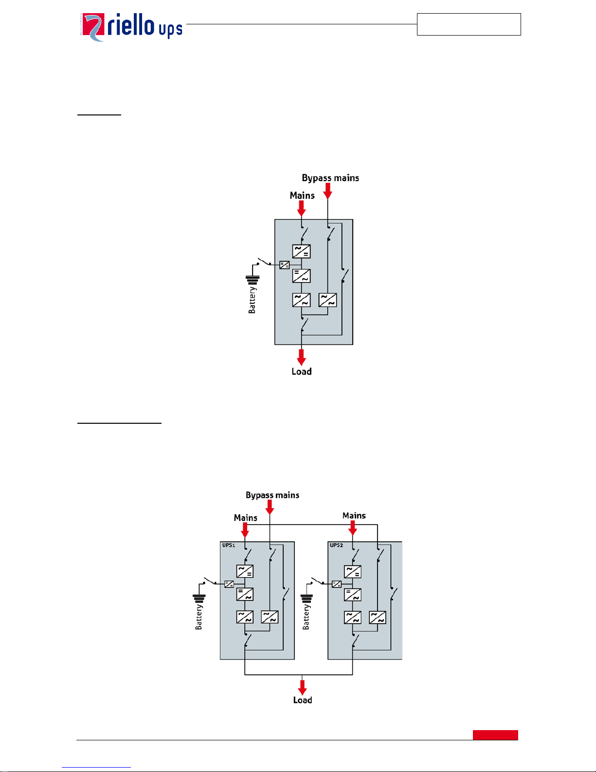
Single UPS
The single version of the system, nor mally used for simple in stallations, can be ex tended to up to 8 units to sat isfy increases
in load power or to introduce a level of redundancy. The same group can function as a frequency converter of 50/60 Hz
and vice versa with or without battery by a simple arrangement that can be done in site (refer to dedicated paragraph).
Parallel configuration
Up to 8 UPSs can be c onne cte d in parallel to increase the pow er of the uninterruptible power system ( power parallel) or to
enhance its reliability (redundant parallel).
The system is defined as “redundant parallel” when the block of one or several UPSs does not determine the loss of the
power supply.
All the UPSs fed the load simultaneously with automatic sharing of the current.
UPS in 1+1 redundant configuration
UPS single module
Page 6
MASTER HE
SPTMHEE3T16FREN
5
The units exchange information on the operating status and the sync signals by the connections in loop with dual
redundancy. This means that even in the event of the accidental interruption of both connections, only the UPS affected
by this interruption cuts itself off, while the other one continues to operate without any interference.
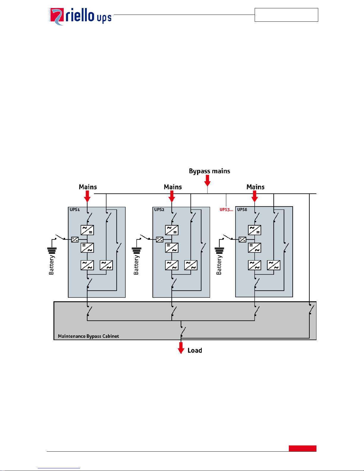
The “Hot System Expansio n ” (HSE) feature means that a new UPS can be ad ded t o t he s y stem while the other units are
on-line and powering the load from the inverter.
The integrated UPS will configure itself automatically with the system data without any disturbance to the load.
In configurations with more t han tw o units, to i mprove the nor mal and ex traordinary mainten ance operatio ns, it is adv isable
to install an external maintenance by-pass and to inhibit the UPS’s internal one.
The UPS will be equipped with terminal to connect the following auxiliary contacts:
• External Maintenance Switch
• External Load Output Switch
The parallel system may function w ith a separat e battery or a single battery, that is, one battery shared by severa l UPSs.
In the case of loss of redundancy the system has an alarm message.
Parallel configuration up to 8 units
In parallel systems, the “Efficiency Control System” (ECS) function enables the UPS to be switched on and off
automatically according to lo ad variations, w hile retaining the l evel of redundan cy defined by the oper ator. This signifi cantly
reduces the total energy dissipated by the system since only those UPSs required to power the connected loa d remain
switched on (for example during the night or at weekends).
Page 7

MASTER HE
SPTMHEE3T16FREN
6
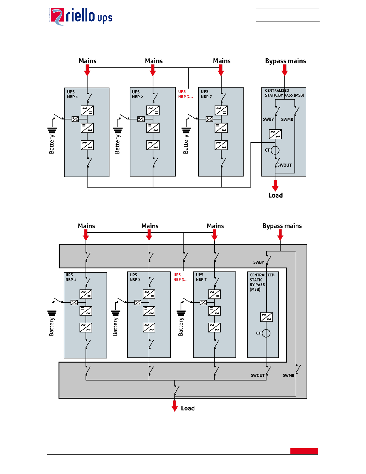
Centralized By-pass: Master Static Bypass (MSB)
The configuration with centralized By-pass comprises up to UPS modules (MHE NBP type) having not embedded static
switch connected in parallel and a separated By-pass section. The By-pass unit is equipped with a static switch which
automatically switches the power supplied to the load by the whole system directly to the mains power supply and vice
versa. Switching is needed during system maintenance operations, or when the whole system is unable to support the
load due to overloads or output short circuits over the current limits.
This configuration assumes the selection of n UPS modules having the same power rating.
The following site prescriptions should be taken into account for the site planning:
• Distance between UPS module and central by-pass shall not exceed 40 meters
• Communication bus cable between units shall not exceed 50 meters
• Total communication ring (UPS units and by-pass) shall not exceed 150 meters
• Battery can be arranged as common or separate (same as distributed parallel system)
• Maintenance bypass is part of the system either embedded in Riello UPS solution (Fig. 1) or supplied by the
customer together with all Input/Output/distribution switches (Fig. 2)
This manually control switch will enable the load feeding directly from the mains insulating the UPS whenever
there is an intervention on its critical parts.
According with site arrangement and UPS modules pairing layout, it will be possible to arrange for MSB having switches
inside (Fig 1) or MSB without any breaker, leaving the coupling arrangement to the customer which shall ensure handy
and safe operations during maintenanc e. (Fig 2)
These two different layouts modify the system current reading but it won’t affect the system operation.
Below we resume the two different scenarios according with system operations either on Inverter or bypass mode:
Display MHE NBP Display MHE MSB
Riello UPS will provide the system as for Fig. 1
System on
inverter
Unit current in: kW, kVA, peak, rms and %
refers to single unit capacity
System current in: kW, kVA, peak, rms, and %
refers to MSB capacity
System on static
bypass
No info
System current in: kW, kVA, peak, rms and %
referred to MSB capacity with inverters locked
(fault) or % referred to unit modules with
inverters ready to supply load.
Riello UPS will provide the system as for Fig. 2
System on
inverter
Unit current in: kW, kVA, peak, rms and %
refers to single unit capacity
System current in % referred to unit module
(master one will pass the data) and not MSB
capacity
System on static
bypass
No info
System current in: kW, kVA, peak, rms and %
referred to MSB capacity with inverters locked
(fault) or % referred to unit modules with
inverters ready to supply load.
Page 8
MASTER HE
SPTMHEE3T16FREN
7
Fig 1. System configuration with centralized bypass and switches:
Fig 2. System configuration with centralized bypass without:
NOTE: It is warmly suggested to arrange a proper on site procedure (written or via castell key mechanical
interlock) so that SWOUT can be open just after SWBY opening manoeuvre.
Page 9
MASTER HE
SPTMHEE3T16FREN
8
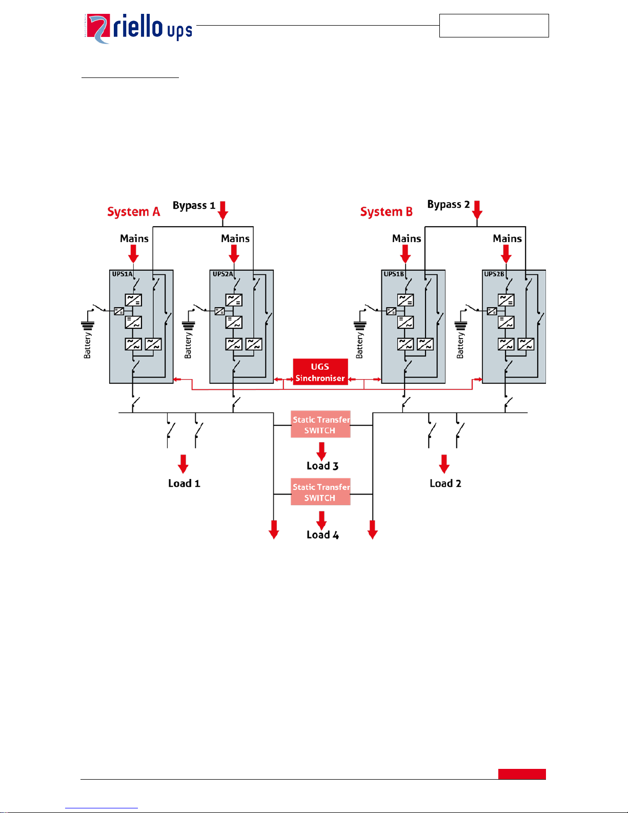
Dual Bus System (UGS)
Two independent systems can be configured in Dual Bus with a single or separate power source.
The synchronization option (UGS) keeps the outputs of the two systems constantly synchronized, regardless of the input
variations and when the system is powered by the battery.
Each system comprises up to a maximum of 8 parallel UPSs. Finally up to 16 units might be mutually synchronized.
This system has been designed for configurations that use the STS (Static Transfer Switch) since it guarantees switching
from one continuous source to the other without disturbances to the loads.
Note: UGS may operate with parallel systems either in distributed or centralized by pass arrangement. Refer to dedicated
manual for installation and operations details.
Page 10
MASTER HE
SPTMHEE3T16FREN
9
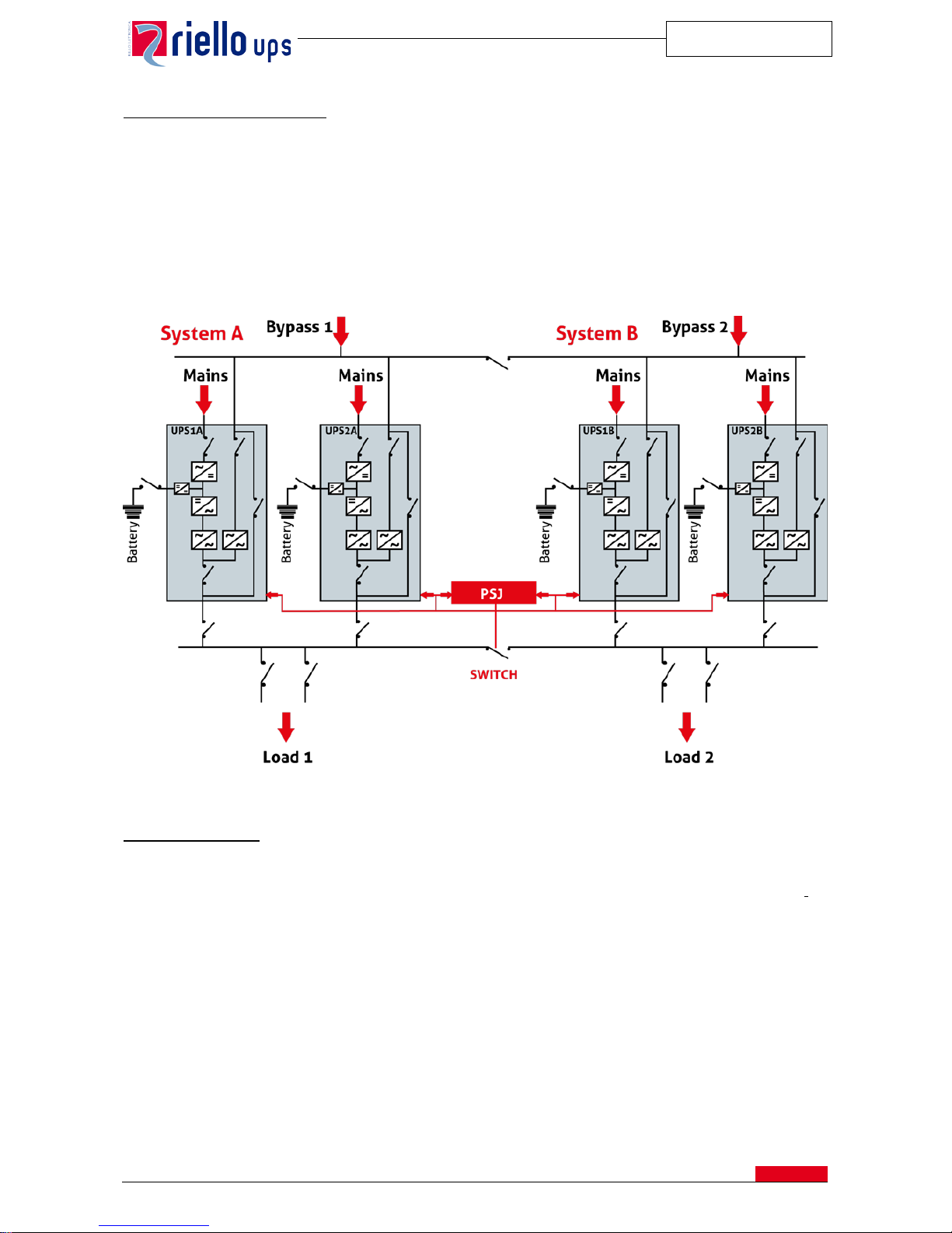
Dynamic Dual Bus System (PSJ)
Two independent systems (up to 4 units each) can be connected in a “Dynamic Dual Bus” configuration by means of the
PSJ (Parallel System Joiner) option.
This enables the two systems to be joined to form a single system when, for example, part of one system is undergoing
maintenance and it is felt appropriate to use the redundant UPS for both bars of the load. The synchronization and the
equal distribution of power is guaranteed by the PSJ.
This characteristic provides an extreme flexibility of the systems in case of maintenance or when is necessary to modify
the redundancy level between the two bus.
Note: PSJ operates with distributed parallel systems, only.
Frequency Converter
Units in standard configuration at 400 V can operate as frequency converters (50/60 Hz and vice versa), whether or not
batteries are present. This feature can be set at the commissioning. The bypass is inhibited in this configuration and
frequency converters with operating voltages other than 400 V, such as 440 V, 460V, etc. can be supplied on request.
With such configuration the UPS can be used without input neutral cable.
Note: For Frequency converter applications please contact your sales representative to ensure that converter layout and
technical arrangements comply with all tender requirements.
Page 11
MASTER HE
SPTMHEE3T16FREN
10
6. UPS DESCRIPTI ON
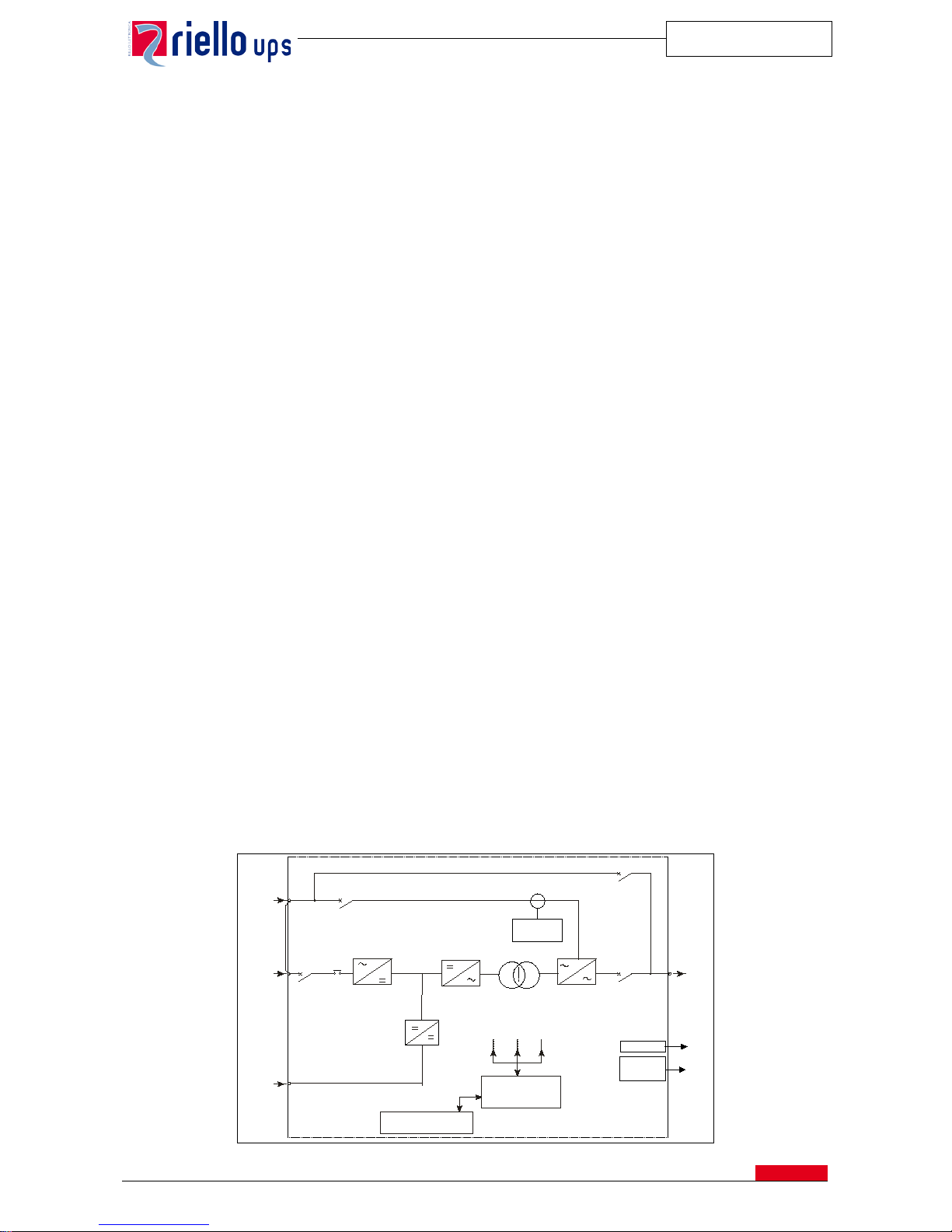
The uninterruptible power supply can be set to operate in four operating modes: ON-LINE, STAND-BY ON, SMART
ACTIVE and STAND-BY OFF.
Mode: ON-LINE
• Normal Operation: The rectifier draws energy from the mains to power the inverter and keep the batteries
charged; the inverter powers the load with voltage and frequency stabilised and in sync with the by-pass mains,
if appropriate.
• Emergency operation: when the main s power supply goes out of the pre-set limits, the rectifier switches off an d
the inverter is powered fr om the batt ery for the envisage d back-up t ime without a ny distur bance to the load. When
the mains power supply is rest ored, the Rectifier star ts to operate gradually (power walk in), pow ering the batteries
again and charging the inverter
• By-pass operation: in the event of an inverter overload beyond the envisaged limits, or a manual shutdown, the
load is automatically transferred onto the by-pass mains by means of t h e Static switch without any disturb an ce to
the load.
Mode: STAND-BY ON
The load is normally powered from the by-pass mains, the rectifier keeps the batteries charged. W hen the mains goes
outside the preset range, the load is transferred automatically onto the inverter (within three milliseconds) until the mains
returns to a suitable level.
This mode is suitable for powering loads that are not sensitive to mains interference, thus allowing increased system
efficiency of up to 98%.
Mode: SMART ACTIVE
When the Master HE is configured in SMART ACTIVE mode, it automatically defines whether to operate in ON-LINE or
STAND-BY OFF mode.
This is done by monitoring the by-pass mains: if this remains suitable for a defined period, the system sets itself to STAND BY ON mode; otherwise it remains in ON-LINE mode.
Mode : STAND-BY OFF
When the mains power supply is present, the rectifier keeps the batteries charged and the inverter is switched off. When
the mains fails, the rectifier switches off and the inverter is activated in approx. 200 ms, using the battery energy.
This application is suitable for the power supply of emergency lighting, as defined by standard EN 50171.
The block diagram of the Master HE system is shown below:
SWBY
SWIN
SWMB
SWOUT
Inverter
Static Switch
Control logic circuit
with microprocessor
PFC
Converter
Mains
Bypass
Mains
Battery
Out
Signaling and Control
panel
Backfeed
Protection
Alarms Card
Comunication Card
SNMP, MODBUS;
JBUS etc.
Step-UP/Step-Down
Converter
TL
Page 12
MASTER HE
SPTMHEE3T16FREN
11
6.1. AC/DC Converter
The AC/DC Converter conver ts th e alter nate volta ge int o d irect v oltage to power the inverter at nomina l loa d a nd to charge
the batteries. The input stage of Master HE UPS is realized with a t echnol ogy such a s to reduc e the har monic s of cur ren t
rejected into the mains by up to 3% and increase the power factor up to the unit from 10 to 100% of the load (see the
tables with the Technical Data at the end of the present specifications).
6.1.1 Easy Source
Master HE is designed in order to reduce at minimum the impact on the mains source or on the upstream Generator Set.
In detail the features are as follow:
• Input Harmonics: thanks to a low input harmonics content of the and the high power factor, the installation
costs are reduced as well as the sizing of a possible generator set upstream.
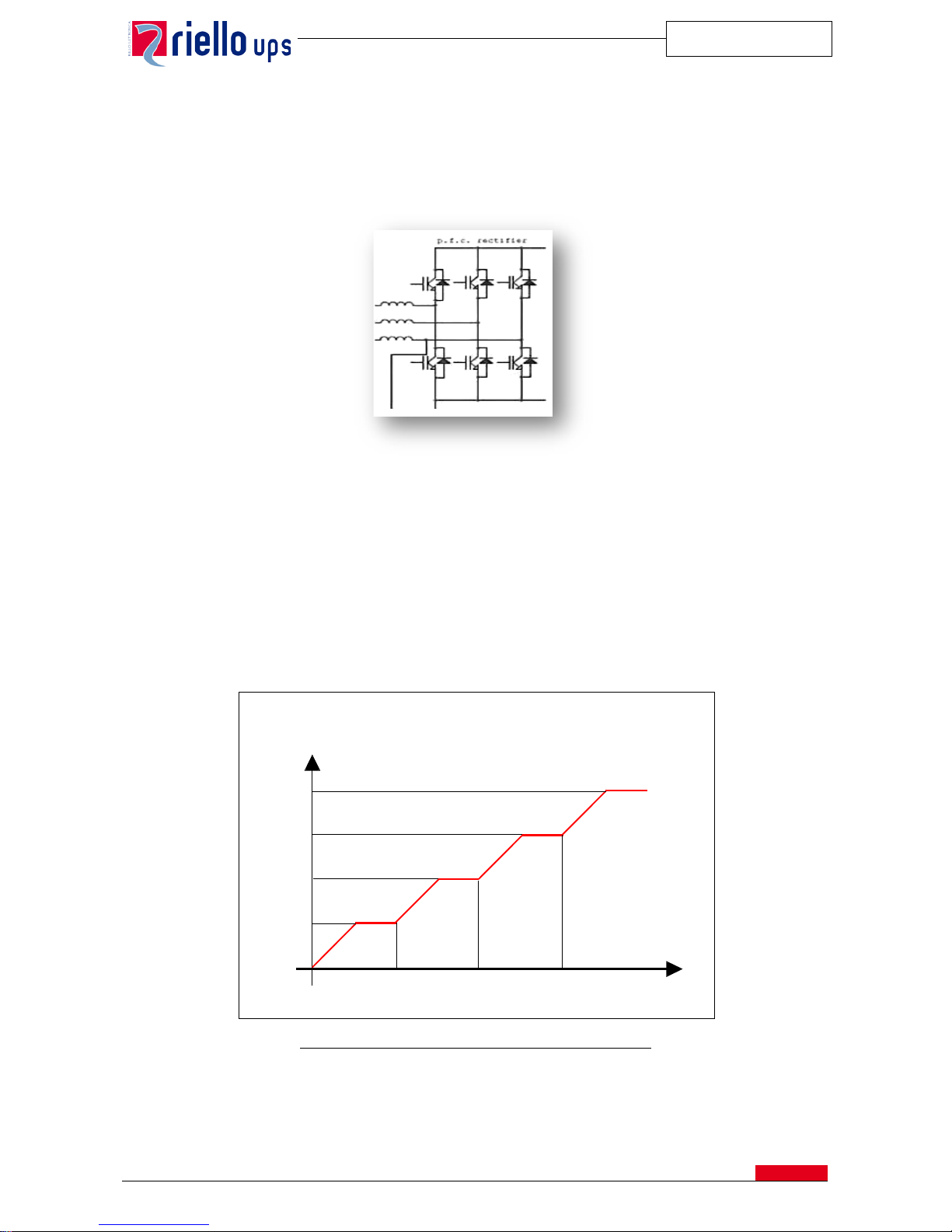
• Power Walk-In duration: when the input vo ltag e is app lie d to the rectifier, as per example after a mains power
failure, this reaches the nominal power progressively in a programmable time from 0 to 30 seconds.
• Power Walk-in start delay: in parallel configurations the start-up of the rectifiers can be delayed to reduce the
impact to any generator located upstream. The delayed start-up is programmable up to 120 seconds.
Example of calibration from the rectifiers in a parallel system
• Inhibition of the battery charge current: while the UPS is operating with a generator set, battery recharging
can be excluded and all the available power can be used to feed the load.
UPS1
UPS1+UPS2
UPS1+
UPS2+
UPS 3
UPS1+
UPS2+
UPS3+
UPS4
Potenza Gruppo
elettrogeno (kVA)
25 %
50 %
75 %
100 %
30
60
90
Secondi
Power of
Generator Group (kVA)
Seconds
Page 13

MASTER HE
SPTMHEE3T16FREN
12
• Inhibition of bypass synchronism: in case of the generator set with a very unstable output frequency, the
Inverter synchronization with bypass can be inhibited. In such as case the inverter generates an output voltage
in the free running mode by us ing th e internal oscillator. Consequently, the tr ansfer of the load on the bypass is
not allowed.
The “battery recharge current” and “Inverter Synchro with bypass” inhibitions are activated by a remote contact of the
generator set connected to the optional Rely Card (see Chapter 12 – Options ).
6.1. DC/DC Converter
The DC/DC converter takes the output direct current from PFC converter to allow the battery recharge. Such a system
closes inside it a STEP-UP/STEP-DO WN converter that takes care o f the charging an d discharging of the battery, reduc ing
drastically the current ripple in the battery. The DC/DC converter is also characterized by the following fundamental
function:
6.2.1 Battery Care System
The “Battery Care System” is a set of functions to control, manage and preserve the battery as long as possible.
a) Battery Recharging: This UPS is suitable for hermetic lead batteries (VRLA), AGM, open vase and Ni-Cd.
Depending on the battery type, two recharge methods are available:
• Cyclical rechar ging ( factory set): the state of the battery ch arge is k ept co nstantly under cont rol an d w hen
the charge level drops below the establi she d lev el, a re char g e cyc le start s up automatically following the IU
characteristic (EN 50272-2). In any case the UPS automatically runs a top-up charge cycle every 24 hours.
• Two level recharging (configurable): this recharge is carried out with two levels of current at two voltage
levels following th e IU
1 U2
characteristic (EN 50272-2). During the first phase the charging takes place at
the rapid charge voltage (U
1
), followed by a second phase at the floating charge level (U2). Both these
recharge values are ensured with temperature compensation of the recharge current as requ ired by the
battery manufacturers so that battery life is not jeopardize. This type of recharge can be configured on-site
and is mainly used with open vase or Ni-Cd batteries.
b) Battery test: in normal operating conditions the battery is checked automatically at regular intervals or on
manual command. The test takes place without appreciably discharging the battery, in complete safety for the
load and without compromising the battery service life. If the test has a negative outcome, a report signal will
appear on the UPS panel and remotely.
c) Protection against slow discharge: in the event of discharges of long duration and low load, the end of
discharge voltage is raised to approx. 1.8 V/el as prescribed by the battery manufacturers so at to avoid
damaging the batteries.
d) Current Ripple: Thanks to the STEP-UP/STEP-DOWN converter, that provides to recharge and discharge the
battery, the current rippl e in the battery is extremely reduced. This feat ur e el im inat es one o f the main causes of
reduced battery reliability.
6.2. DC/AC Converter
The DC/AC converter convert s direct voltage in to stabilized, alternate s inusoi dal curre nt to supply the load. With the UP S
in ON-LINE mode, the load is always powered from the inverter.
This comprises a three phase inverter with IGBT (Isolated Gate Bipolar Transistor), a transistor that allows high switching
frequencies (>20 kHz) and consequently low consumption and low noise.
The inverter output is connected to the transformer, thus ensuring galvanic isolation between output and battery.
Voltage regulation
Output voltage is regulate d by using the inde pendent p hase control , a characteri stic that all ow s a better static and dy namic
response. In detail:
a) Static condition: the output voltage from the inverter remains within ±1% for all the input tension variations
within the permissible limits;
b) Dynamic condition: for load variations from 0 to 1 00%, the output volt age remains w ithin ±5% below the v alues
defined by class 1 of standard EN 62040-3.
Page 14

MASTER HE
SPTMHEE3T16FREN
13
Frequency regulation
The inverter output frequency is generated autonomously by an internal oscillator in synch with that of the by-pass mains;
the frequency stability towards the load therefore depends on the operating conditions:
a) Frequency stability
a. With mains available: the internal oscillator follows the variations in frequency of the by-pass mains,
according to the set value, which is normally ±2% (can be calibrated form ±1% al ±6%).
b. W ith mains not available: the inverter generates the output current frequency autonomously with a stability
of ±0,05%.
b) Speed of frequency variation
The maximum output fr eque ncy variatio n of the invert er t o rea ch onto t hat of the bac kup by -pass mains is 2Hz/s
for the single UPS and 1Hz/s for the parallel version.
Output voltage distortion
The regulation of the inver ter guarantees the o utput voltage distort ion with linear l oads within 1% (max imum 2% with battery
nearly discharged). W ith non-linear loads, as defined by standard EN 62040-3, the output voltage distortion does not
exceed 3%.
Output power
The Inverter is sized to supply 100% of active power with nominal load pf 1 in the temperature operating range without
downgrading.
MASTER HE supplies capacitive loads with PF form 1 to 0,9 with no any power downgrading applied.
Overload
The inverter is sized to supply a power overload (kVA) of 110% for 1 hour, 125% for 10 minutes and 150% for 1 minute,
on the three phases. On one phase, the limit is 200% for 6 s.
If the time or power limits are exceeded, the load is transferred onto the by-pass mains.
Short circuit capacity
In the event of a short circuit on the load and with power supply from the battery, the inverter can supply a current limited
to 180% for 1 s in the event of a short circuit on the three phases, and 300% for 1 s in the presence of a short circuit
between phase and neutral.
Symmetry of output voltage
In all conditions, the sy mmetry output v oltage i s guara nteed w ithin ±1% , for bala nced loads and ± 2% f or 100% u nbalan ced
loads (e.g. one phase at nominal load, the other two without load).
Phase displacement
The inverter three phase output voltages are guaranteed with a phase shift angle of 120° ±1° for 100% balanced and
unbalanced loads.
Page 15

MASTER HE
SPTMHEE3T16FREN
14
6.3. Static switch
The Static Switch is an electronic device that transfers the load onto the by-pass mains without any break in power in the
following circumstances:
a) manual shutdown of the inverter;
b) exceeding of the inverter overload limits;
c) exceeding of the internal over temperature limits;
d) inverter fault;
e) DC voltage outside the admitted range.
If at the time of switching the inverter voltage is not in sync with that of the by-pass mains, the transfer takes place with a
delay to avoid possible damage to the load. However this value can be adjustable to cover all the requirements of the
various types of load Refer to Technical data table.
By-pass mains voltage
Transfer onto the by-pass mains only takes place if the v oltage and frequency are consider ed “suitable” to power the load.
The limits of acceptability are defined by the user in relation to the connected load:
• Voltage window: ±10% (can be calibrated from ±5% to ±25%);
• Frequency window: ±1 Hz (can be calibrated ±1 Hz to ±6 Hz).
Overload
In order to guarantee th e maximum of service cont inuity, the static sw itch does not hav e protection f or overload. This allows
the compatibility w ith any typ e of syst em, commi ssioning t o protection devices , externally installe d, the sel ectivity ensuring.
The UPS Static switch is sized to support the following overloads:
• 110% for 60 minutes
• 125% for 10 minutes
• 150% for 1 minute
The short-circuit capacity may also vary according to the load (see table in the Technical Data section).
Page 16
MASTER HE
SPTMHEE3T16FREN
15
7. CONTROL PANEL
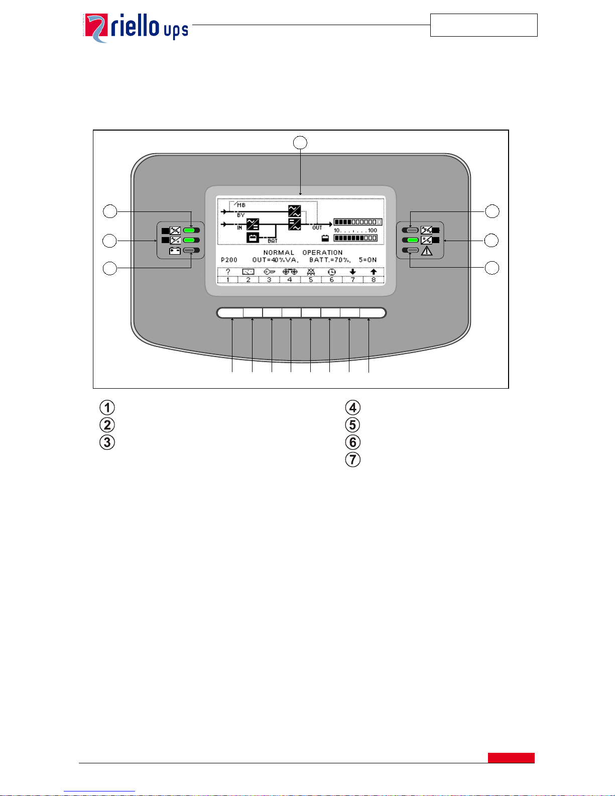
The control panel located at the front of the equipment may be used to monitor and control all the parameters of the UPS
and the batteries connecte d to it . The oper atin g statu s of the UPS is show n on a liquid cryst al displ ay (LCD), with two rows
of 40 characters and four LEDs with three operating states: On (steady), On (flashing), and Off.
LED Bypass input line indicator
LED bypass output
LED Mains input line indicator
LED Normal output
LED Battery indicator
LED alarm for internal
Graphic display
F1, F2, F3, F4, F5, F6, F7, F8: FUNCTION KEYS
The function of each key is shown at the bottom of the display screen and varies according to the menu displayed.
The display shows the ev ent history log up to 120; the me as u r emen ts and a sso cia ted ala r m s ar e recorded for each event.
The messages are available in the following languages: Italian, English, French, German, Spanish, Portuguese, Dutch,
Swedish, Polish, Hungarian, Turkish, Czech, Romanian and Russian (as options).
1
2
3
4
5
6
7
F1
F2
F3
F4
F5
F6
F7
F8
Page 17
MASTER HE
SPTMHEE3T16FREN
16
Measurements
• Input voltage and frequency
• By-pass voltage and frequency
• Input power
• Output voltage and frequency
• Output power
• Output power peak
• Battery voltage
• Battery recharge/discharge current
• Inverter input voltage
• Internal temperature (logic control, rectifier, Inverter, static switch and magnetic components)
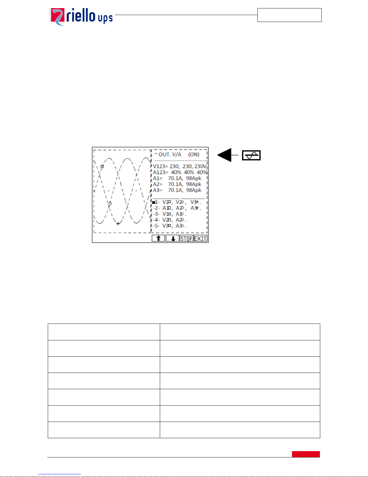
• Sinewave view of the following signals :
- Input Current /Output Current
- Input Voltage/ Output Voltage
• Hours of operation on inverter
• Hours of operation on by-pass
• Hours of operation on battery
• Battery attuation time
• Number of complete battery discharges
Messages
The alarm messages are the following:
DISTURBANCES ONBY-PASS LINE
Presence of disturbances on the by-pass line.
MANUAL BY-PASS SWITCH CLOSED
The manual maintenance by-pass switch is closed.
INCORRECT BY-PASS VOLTAGE OR SWBY,
FSCR OFF
The line voltage or frequency is outside the limits or the switch is
open.
INCORRECT VOLTAGE SUPPLY OR SWIN
OFF
The rectifier power supply voltage is outside the limits or the rectifier
is faulty.
PREALARM FOR MINIMAL BATTERY LIFE
The battery is discharging and has reached the minimum back-up
time value (can be calibrated).
BATTERY TEST FAILED OR BATTERY
SWITCH OPEN
The battery test has failed or the battery switch is open.
SUPPLY VOLTAGE LOW
The battery voltage is below the preset limit.
Page 18
MASTER HE
SPTMHEE3T16FREN
17
OUTPUT OVERLOAD
The load connected to the inverter has exceeded the nominal value
in kVA.
LOAD SUPPLIED BY BY-PASS PER
MINIMUM LOAD
When the load is less than the value set by the operator, it is
transferred onto the bypass line.
INTERNAL DAMAGE number
Internal fault, details of the alarm are provided by a code.
LOAD TEMPORARILY ON BY-PASS
The load is temporarily on the bypass due to inrush current or
inverter start-up.
LOAD ON BY-PASS DUE TO OUTPUT
OVERLOAD
Load on bypass due to exceeding of the inverter overload limits.
ACTIVE BY-PASS COMMAND
Load forced onto bypass.
REMOTE COMMAND FOR BY-
PASS: ACTIVE
Load forced onto by-pass by a remote command.
OVERLOAD TEMPERATURE OR
VENTILATION DAMAGED
The temperature inside the cabinet has exceeded the maximum limit
due to too high ambient temperature or ventilation fault.
INPUT PHASE SEQUENCE INCORRECT
Indicates that the sequence of the input phase is incorrect.
MISSING OUTPUT VOLTAGE
Alarm when the output voltage is not present because the SWOUT
and SWMB are open at the same time.
AUTO-OFF Timer: Toff= 0: 0', Ton= 0: 0'
Setting of the date and time of automatic UPS start-up and
shutdown.
8. DISCONNECTING SWITCHES
The UPS is equipped w ith four sw itches under l oad located o n the front of t he cabinet tha t can be acces sed by the ope ning
of the door:
• Rectifier input;
• By-pass mains input;
• Output load;
• Maintenance by-pass.
The battery switch is located in the battery cabinet or in a wall panel.
Page 19
MASTER HE
SPTMHEE3T16FREN
18
9. COMMUNICATION
The alarms, commands and the communication software supplied together with the UPS to interface the unit with the
system are listed below.
If these are not sufficient, please see the Options chapter.
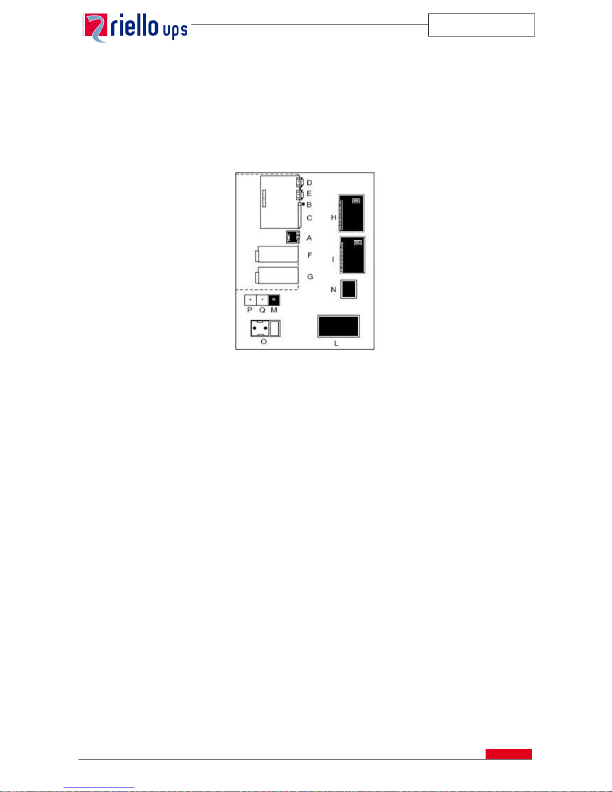
Two DB9 connectors are available for RS232 connection; these outputs can be connect to a remote computer or to a
Modem.
Interface card with connectors for signa ls and remo te com ma nds
9.1. Report Signals
These are provided by means of voltage-free relay contacts (the maximum capacity of the contacts is: 1 A – 42 V):
• Battery low;
• Battery discharged;
• Load on by-pass or UPS fault.
9.2. Commands
The following commands in the UPS can be activated by means of an external voltage at + 12 V 80 mA (max):
• ON/OFF Inverter (Such alarm can be modified as listed on pages 28-29);
• Complete shutdown of the UPS.
This signals reporting can be set.
9.3. Emergency Power Off (E.P.O.)
In the event of an emergency the UPS can be completely shut down by an external command.
A-PARALLEL (optional)
H- REMOTE ALARMS (optional)
B- EPO (emergency power off)
I- REMOTE ALARMS (optional)
C- REMOTE
L- MODEM (optional)
D- RS232-1
M-battery temperature sensor (optional)
E- RS232-2
N- UGS (optional)
F- SLOT 1 (main)
O- 230V-auxilliary outlet
G- SLOT 2 (aux)
P- SWOUT aux
Q- SWMB aux
Page 20
MASTER HE
SPTMHEE3T16FREN
19
9.4. Monitoring and control software
The system is provided with Powershield³ monitoring and control software with the following features:
• Event chronology;
• Total events management;
• E-mail, modem, SNMP Agent support;
• Sequential shutdown of all the PCs in the network, saving the active work of the most varied applications.
10. UPS CABINET
The cabinet is made in galvanized steel with degree of protection IP20 even with the front door open. In addition, on
request, different versions with higher protection degrees are available.
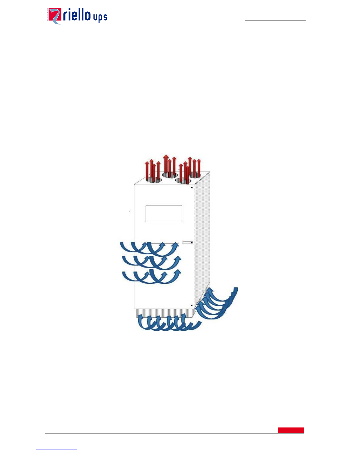
The forced ventilation is ensured by means of fans at the top; air intake is from the front, and output is from the top.
The parts with greater d issip ation, such a s the power modules and magnetic par ts, are mo nitor ed by temperat ure sensor s.
Air flow through the UPS
11. INSTALLATION
The UPS are designed to allow all the regular and extraordinary maintenance opera tion s f r om the fr ont , th us making back
or side access superfluou s. The cables input is fr om th e bott om, and opt ionally can be po ssible requir e the cable entr ance
from the top (please refer to the description in the section of options).
Pallet lifters may be used to move the systems.
Page 21
MASTER HE
SPTMHEE3T16FREN
20
12. OPTION
12.1. Communication
The software PowerNETGuard is a centralized management program used by the UPS that operates through the SNMP
communication protocol. It is an ideal instrument for EDP manager in medium and large scale Data Center.
The main features are the following:
• Display at various levels of geographical areas, building plans, maps.
• Multi-user accesses with several levels of safety.
• Compatible with standard RFC 1628 SNMP agents.
• Creation of graphics and saving on file for physical input and output values.
• Alarm notification via e-mail and SMS.
• Integrated Wap Server for the display of the alarms.
• Suitable for operation with Windows operating systems: (98, ME, NT, 2000, 200 3, Xp and Vista) Linux , M ac OS
X, Solaris 8 and 9.
Note: the complete and updated list of options is available on the website: www.riello-ups.
com
Hardware
Two slots are available inside the device, at the bottom, to house two of the following communication options:
a) NetMan 102 Plus: network agent for the management of the UPS connected directly on the LAN 10/100Mbps
using the main protocol of network communication (TCP/IP, HTTP and SNMP). A MODEM can also be
connected to the same device.
b) Netman 202 Plus: network agent like Netman 102 Plus, but improved with USB host, SNMP v1 and v3,
maximum expandability and firmware upgradeable via USB port FTP and http.
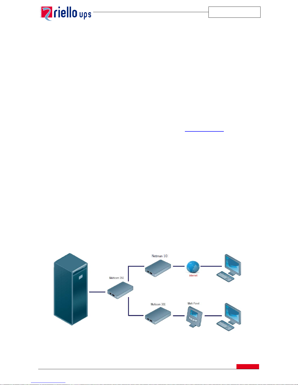
c) MultiCom 302: Modbus/Jbus protocol converter by means of RS232 or RS485 output for the monitoring of
UPSs in BMS (Build Management System). It also manages a second independent RS232 serial line that can
be used to connect other devices such as NetMan Plus or a PC.
d) MultiCom 352: a device that makes it possible to connect two devices to a single UPS serial port. It can be
used in all cases where several serial connections are required for multiple interrogation of the UPS.
The communication cards can be used simultaneously in various combinations to achieve greater flexibility and therefore
enhanced services, as can be seen in the following example:
Page 22

MASTER HE
SPTMHEE3T16FREN
21
In addition to the cards above mentioned the following communication options are available:
e) Multi I/O Card: an accessor y mounted inside t he UPS that c onverts external signals from t he UPS (e.g. amb ient
temperature, battery room temperature, etc.) into signals by means of relay contacts or on an RS485 serial
output in MODBUS protocol.
f) Contact card with programmable power relay (5A-250V) for connecting a remote control device. The
following default alarm signals are available:
a. Load on inverter;
b. Load on mains power;
c. Low battery;
d. Overload;
e. Over-temperature;
f. Load on maintenance by-pass.
There are also two programmable inputs (24VCA) for: “battery charge inhibition” and “by-pass inhibition” that can be used
when is connected a generator-set.
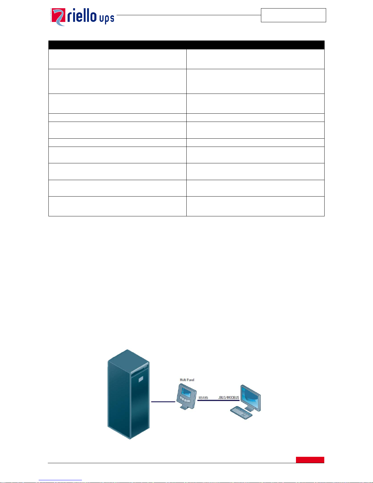
The UPS is predisposed to house two alarm cards, having so up to 12 programmable alarms and 4 inputs. The settable
alarms are listed in the following table:
ALARM DESCRIPTION
INTERFERENCE ON BYPASS LINE
Disturbance on the bypass line (e.g. voltage peaks,
harmonic distortion etc.) while the voltage and frequency
values remain within acceptable limits. The inverter is not
synchronised with the mains power supply.
MANUAL BY-PASS, SWMB-ON
SWMB Manual by-pass switch is closed
FAULTY BY-PASS VOLTAGE or SWBY, FSCR OFF
This alarm is present if the input voltage of the bypass
line is not correct, or the SWBY switch is open.
FAULTY MAINS SUPPLY VOLTAGE or SWIN
OFF
The voltage supplied to the rectifier is incorrect or the
SWIN switch is open. The battery is in discharge mode.
PRE-ALARM FOR LOW BATTERY VOLTAGE
The battery voltage is below the calculated value to
furnish about 5 minutes of autonomy; the pre-alarm value
is settable.
DISHCHARGED BATTERY OR BATTERY SWITCH
(SWB) OPEN
The battery is discharged or the switch is open.
LOW POWER VOLTAGE or OVERLOAD
The power voltage is lower than the nominal value or
there is an output overload.
OUTPUT OVERLOAD
The inverter is overload status.
BY-PASS FOR OUTPUT VA < AUTO_OFF VALUE
This alarm is present when the power expressed in %VA,
absorbed by the load is lower than the "AUTOOFF" value.
(function to be activated when the system is powered up).
INTERNAL FAULT: number
An internal anomaly is present
TRANSITORY BY-PASS
The load is powered temporarily by the bypass line (e.g.
for transitory current peaks)
BY-PASS FOR OVERLOAD ON OUTPUT
The load is powered by the bypass line for overloads on
the inverter in excess of the set limits.
BY-PASS COMMAND ACTIVE; DISABLED.
This alarm indicates when the load is forced over to the
bypass line using a command on the front panel. The
inverter is switched off.
REMOTE COMMAND FOR BY-PASS: ACTIVE/
DISABLED.
This alarm indicates when the load is forced over to the
bypass line via a remote command. The inverter is
switched off.
OVERTEMPERATURE or FAULT ON FANS.
This alarm indicates an internal overtemperature caused
by an increase in environment temperature outside the
set limit s or due to malfunctioning of the fans.
FAULTY INPUT PHASE SEQUENCE
The input sequence phase for the by-pass line is
incorrect.
Page 23
MASTER HE
SPTMHEE3T16FREN
22
ALARM DESCRIPTION
OUTPUT SWITCH AND MANUAL BY-PASS SWITCH
OPEN
This alarm indicates when there is no output voltage due
to the simultaneous opening of the SWOUT output switch
and the SWMB manual bypass switch.
ACTIVE/DISABLED SHUTDOWN COMMAND.
This alarm indicates when the shutdown command
(Rectifier + Inverter + by-pass) has been activated on the
front panel or through the connection of the RS232
interface (Powershield³).
REMOTE SHUTDOWN COMMAND:
ACTIVATED/DISABLED.
This alarm indicates when the shutdown command
(Rectifier + Inverter + by-pass) has been activated via
remote contact.
CHANGED MEMORY: CODE = NUMBER
Indicates that the system settings have been changed.
BATTERY OVERTEMPERATURE
The temperature in the battery cabinet has exceeded the
set limits.
BATTERY TEST FAILED
The battery test has encountered a battery fault
FAULTY FAN ALARM
This alarm indicates a faulty fan inside the system
(optional function - on request).
FAULT FUSE
This alarm indicates one or more faulty fuses inside the
system (optional function - on request).
FAULT ON PARALLEL CONNECTION
The parallel connection has been interrupted or is
disconnected
AUTO-OFF Timer: Toff= 0: 0', Ton= 0: 0'
This alarm indicates when the daily timer comes in
function set for the automatic UPS start-up and
shutdown. If required this function is enabled at start-up.
12.2. LED Remote mimic panel
It can be connected up to a distance of 200m from the UPS for remote supervising.
The panel provides information about UPS functions:
• Green LED: normal operation;
• Yellow LED: not critical alarm;
• Red LED: alarm.
UPS start-up and shutdown commands can also be sent from the mimic panel.
12.3. Remote graphic panel
Graphic remote panel gets ava ilable remotely on the Graphic Display the information on the UPS status, the measurement s
and the alarms. In addition it i s fitte d a R S485 por t which gets available the same information in JBUS/MODBUS protocol
for the BMS.
The max distance between the UPS and remote panel is approx 300 mt.
RS232
Page 24
MASTER HE
SPTMHEE3T16FREN
23
12.4. Battery cabinet
The battery cabinets are available with the following characteristics:
• protection fuse and switching disconn ect ors;
• Protection degree IP20 with front door open;
• Complete with batteries or empty with connection cables between the compartments (cells).
The size is (WxDxH): 860 x 800 x 1900 mm, weight 200 Kg (empty).
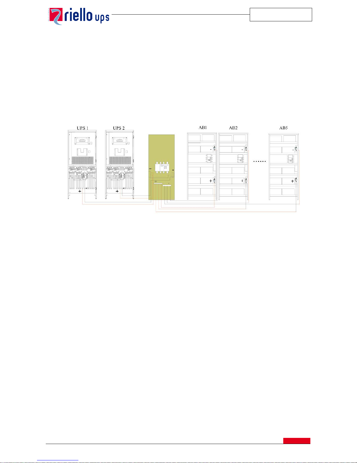
Such battery cabinets can be conne cted in paralle l to reach th e required aut onomy; for more than 2 in parallel it i s advisable
to add a single module cabinet where the paralleling of the cables can be connected. Below an installation example is
provided:
12.5. Starting up from battery (Cold Start)
This device makes it possible to switch on the UPS even in the event of a mains failure using only the battery energy.
12.6. UGS - UPS Group Synchroniser
This allows 2 systems connected i n a “ DUA L BUS” confi gura tion to keep synchronised with each oth er for any variation in
the mains voltage, including total failure. The UGS also allows an RIELLO UPS to be synchronised with another power
source or to an independent non RIELLO UPS system, even one of a different power rating.
The UGS box is designed to be wall-mounted:
• Dimensions (W x D x H): 150 x 70 x110 mm
• Weight: 2 Kg
12.7. PSJ - Parallel Systems Joiner
This allows two UPS units to be con nected in para llel, w ith the syste m on (without interrupti ng output) by me ans of a pow er
coupling switch in accordance with the system indicated in Chapter 4 (Dynamic Dual Bus System) .
The PSJ box is designed to be wall-mounted:
• Dimensions (W x D x H): 300 x 220 x120 mm
• Weight: 2 Kg
12.8. Isolating transformers
Cabinets with a delta/star bypass isolation transformer are available. Such transformers can also be used to recreate the
power supply neutral where this is not present.
In the case of installations with external maintenance bypass, contact the commercial office.
Battery switch
cabinet
Page 25
MASTER HE
SPTMHEE3T16FREN
24
12.9. Voltage adaptation
On request, the UPS can have different input and output voltages according to requirements.
For more information, please contact the sales office.
12.10. Kit for UPS without input and output neutral
The UPS requires input neutral to work correctly. . In applications where the neutral is not available in input and is not
required in output, a dummy neutral can be created using this kit.
This device is used only for reference to the internal logic and not for the supply of power.
12.11. Protection levels
The UPSs can be provided with levels of cabinet protection over IP20 in accordance with standard EN 60529.
12.12. Top cable entry
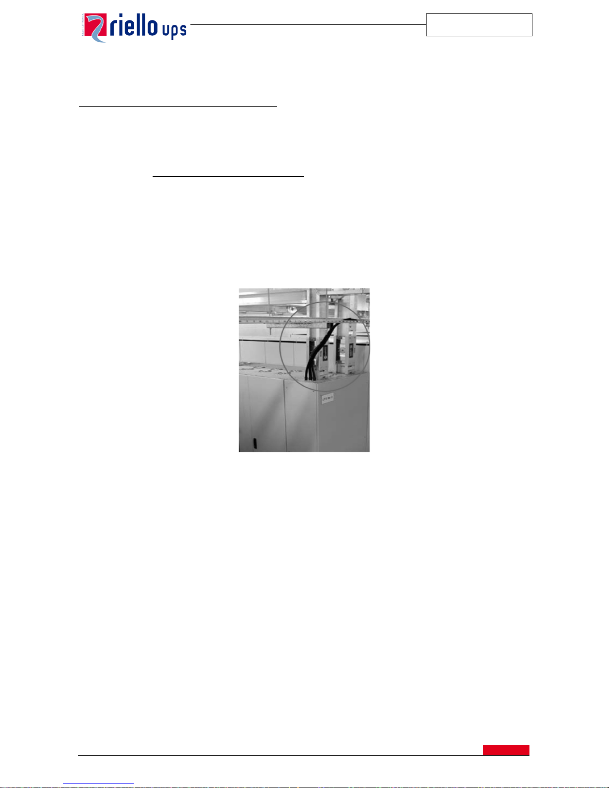
In order to facilitate cable entry from the top, a special cabinet is placed next to the UPS;
Example of Installation with cable entry from the top
There is the availability of two kinds of cabinets:
• Empty Cabinet: size (W x D x H) 400 x 1000 x 1900 mm
• Cabinet with terminals: size (W x D x H): 800 x 1000 x 1900 mm
Page 26
MASTER HE
SPTMHEE3T16FREN
25
12.13. Environmental sensors
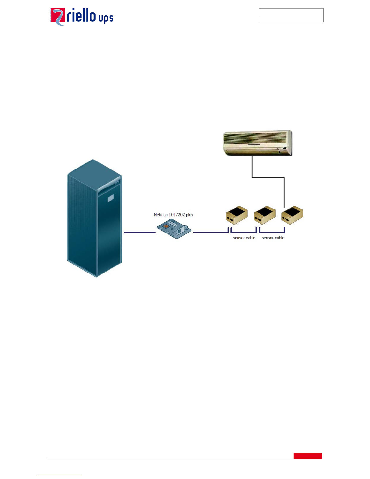
The environmental sensors are devices to be connected to the communication card Netman 101 plus or to a Netman 102
plus, in order to monitor the temperature and humidity of the environment and they have equipped with digital inputs and
outputs opportunely sett abl e.
The available sensors are :
• Temperature: detects ambient temp er atur e
• Humidity & temperature: detects percent of relative humidity and ambient temperature in °C.
• Digital I/O & Temperature: detects the environment temperature in degrees °C and is equipped with a digital
input and output.
12.14. Fan Failure monitoring
In addition to the standard internal tem perature control, the Master HE series can also be fitt ed with a dev ice for monitor ing
the operation of each individual fan. In the event of a fault, an alarm shows on the front panel of the system via relay
contacts and software.
Page 27
MASTER HE
SPTMHEE3T16FREN
26
13. ENVIRONMENATL REQUIREMENTS
Ambient temperature for the UPS
0 ÷ 40° C
Maximum temperature for 8 hours a day
40° C
Average temperature for 24 hours
35° C
Recommended battery temperature
20 ÷ 30° C
Range of relative Humidity
30÷95% max (without condensing)
Maximum Operating Altitude
Up to 1000 m o.s.l.
(derating of 1% each 100 m between 1000 and 4000 m)
Storage Temperature
From -25°C up to 60 °C (UPS)
-15, +40°C (for battery)
14. TECHNICAL DATA
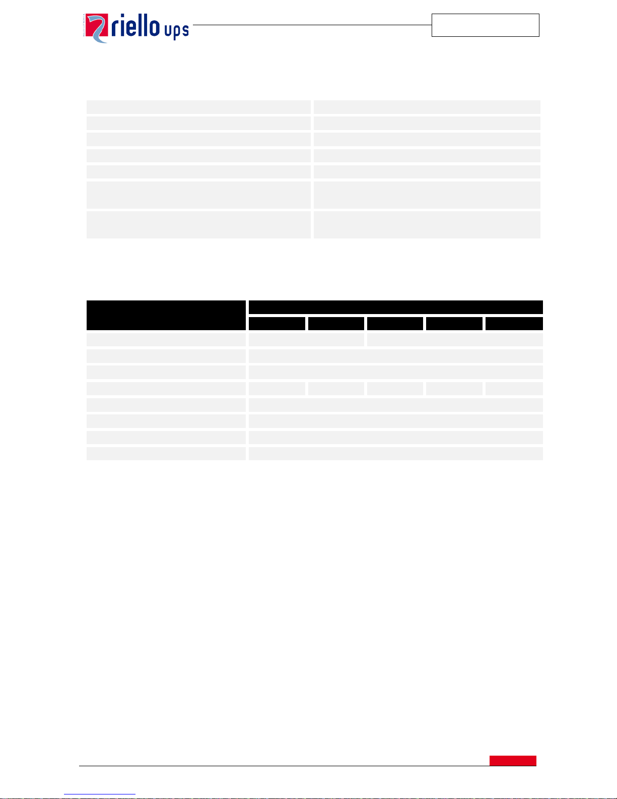
Mechanical Data
UPS Size (kVA)
100 120 160 200 250
Width (mm)
800 1000
Depth (mm)
850
Height (mm)
1900
Weight (Kg)
850
900
1015
1070
1300
Ventilation
Forced by internal fans
Level of cabinet protection
IP20 (higher levels of protection on request)
Input cables
From the bottom
Colour
RAL 7016
Page 28

MASTER HE
SPTMHEE3T16FREN
27
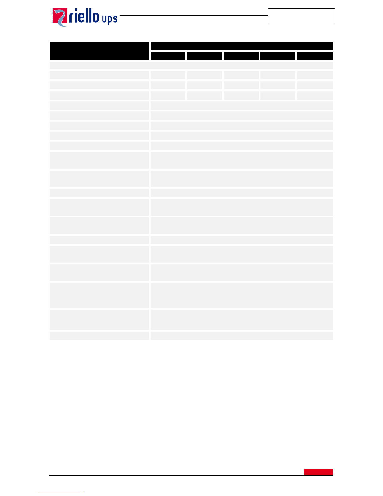
Electrical Data
UPS Size (kVA)
100 120 160 200 250
INPUT
Rated Voltage
400 Vac 3F-phase without neutral
Rated Voltage tolerance (%) without
battery sharing, according with load
rate
+20%, -10% (100% load)
+20%, -20% (85% load)
+20%, -30% (75% load)
+20%, -40% (65% load)
Rated Frequency (Hz)
50/60
Input frequency tolerance
from 45 to 65 Hz
Rated current absorbed at rated
voltage [A]
153 185 245 309 386
Rated power absorbed at rated
voltage [kVA]
106 128 170 214 267
Max current absorbed at full load
and battery in recharge [A]
170 204 273 341 426
Input Power Factor at rated voltage
with battery in recharge (from 25% to
100% load)
>0,99
Current Harmonic distortion (THDi)
with main THDV < 1%
• Load 100%
• Load 75%
• Load 50%
•
Load 25%
<3%
<3%
<5%
<8%
Progressive start of rectifier (Power
Walk-in Duration)
from 0 to 120 second (Configurable)
Delay of Progressive start of rectifier
(Power Walk-in Start Delay )
from 0 to 120 second (Configurable)
D.C. INTERMEDIATE CIRCUIT
Number of lead cells / Battery blocks
(see note 1)
240 (40 batteries)
Rated battery voltage (Vdc)
480
Ripple current with recharged
battery (%)
Approx 0
Float voltage (2,26 V/el., can be
calibrated) – Vdc
542
Recharge Voltage (2,4 V/el., can be
calibrated) – Vdc
576
Maximum output voltage (Vdc)
600
End of discharge voltage Vdc (1,6
V/el, can be calibrated) - Vdc
384
Voltage Compensation with
reference to the battery cabinet
temperature (V per °C)
-0,11%
Maximum current to charge battery
with 240 elements (A). (mains
voltage 400V)
•
Load 100%
18 20 30 37
•
Load 90%
36 45 60 75
•
Load 80%
56 65 90 110
• Load ≤ 70% 66 80 105 130
Page 29
MASTER HE
SPTMHEE3T16FREN
28
Electrical Data
UPS Size (kVA)
100 120 160 200 250
INVERTER
Rated Power [kVA]
100 120 160 200 250
Rated active Power [kW]
100 120 160 200 250
Nominal Current [A]
144 173 231 289 361
Rated Voltage
400 V 3F + N (configurable from 360 V to 420 V)
Rated Frequency
50 o 60 Hz (configurable on site)
Output Rated voltage regulation
from 360 to 420 V
Static variation
±1 %
Dynamic variation
±5%
Restore time within ±1%
20 ms
Conform To the standard EN 62040-3, class 1
Crest current factor (Ipeak/Irms as
per EN 62040-3)
3:1
Voltage distortion with linear load
≤1% (typica), ≤2% (max)
Voltage distortion with non-linear
load (EN 62040-3)
≤3%
Frequency stability with inverter not
synchronized to the by-pass mains.
±0,05 %
Speed of frequency variation
1 Hz/sec (see note 2)
Phase voltage asymmetry with
balanced and unbalanced load.
≤1%
Voltage phase shift with balanced
and unbalanced load.
120 ±1°el
Overload referred to the rated power
• Phase / Phase
•
Phase / Neutral
(@ 25°C environment)
110% for 60 minutes, 125% for 10 min., 150% for 1 min.
200% for 6 seconds
Short circuit Current
• Phase / Phase
•
Phase / Neutral
180% for 1 second
300% for 1 second
Battery mode efficiency (%)
95%
Page 30

MASTER HE
SPTMHEE3T16FREN
29
Electrical Data
UPS Size (kVA)
100 120 160 200 250
BY-PASS
Rated voltage
400 Vca 3fase + N (configurabile da 360 V a 420 V)
Rated voltage tolerance
±20% (can be regulated from ±5 % to ± 25% from the control panel)
Rated frequency
50 or 60 Hz (auto-sensing)
Frequency tolerance
±2% (can be regulated from ± 1% up to a ± 6% from the con t r ol panel)
Switching onto by-pass with Invert er
synchronized (UPS in “Normal
Mode”)
<1 ms
Switching onto by-pass with non-
synchronized Inverter (UPS in
“Normal Mode”)
~100 ms
(configurable up to 200ms)
Switching from by-pass to Inverter
(UPS in “Stand-by On mode”)
4 ms
Overload Capacity of by-pass line
(kVA)
110% for 60 minutes, 125% for 10 minutes, 150% for 1 minute
I2 t SCR bypass (25°C, 8÷10ms) [A2s]
145 k 145 k 405 k 405 k 405 k
Short circuit capacity of by-pass line
(x nominal voltage) I/In
• 1 second
• 500 ms
• 200 ms
• 100 ms
•
10 ms
12
13
15
17
24
10
11
13
14
20
12
13
15
17
24
9.5
10.5
12.5
13.5
19.5
7.5
8.5
10
10.5
15.5
Page 31

MASTER HE
SPTMHEE3T16FREN
30
Electrical Data
UPS Size (kVA)
100 120 160 200 250
SYSTEM
AC/AC efficiency (On line) – [%]
• Full load
• Load 75%
• Load 50%
• Load 25%
95.1
95.2
94.8
92.5
94.5
95.2
95.2
93.5
95.2
95.5
95.3
94.0
94.5
95.3
95.5
94.5
Efficiency system in STAND-BY
mode [%]
• Charge 100%
•
Charge 50%
99
98.5
Neutral size (I/rated current)
1.73 1.44 1,73 1,38 1,1
Dissipated power without load
• [Kw]
• [Kcal/h]
•
[BTU/h] see note 3
1.5
1290
5118
1.5
1290
5118
2.1
1806
7165
2.1
1806
7165
2.5
2150
8530
Dissipated power with 50% of load
• [Kw]
• [Kcal/h]
•
[BTU/h] see note 3
2.7
2358
9358
3
2601
10322
3.9
3392
13462
4.7
4052
16078
5.9
5065
20098
Dissipated power with 100% of load
• KW
• Kcal/h
• BTU/h ((see note 3)
5.2
4430
8790
7
6005
23831
8.1
6937
27527
11.6
10009
39718
14.6
12511
49648
Maximum current dispersion
300 mA maximum
Noise level at 1m from the front
(from 0 to full load ) - [dbA]
65 68
Notes:
(1) The number of Pb elements can vary from 222 to 258
(2) The parallel version can be calibrated from 0,1 to 1Hz/s.
(3) 3.97 BTU = 1kcal.
Page 32

MASTER HE
SPTMHEE3T16FREN
31
Electrical Data
Bypass Size (kVA)
800 kVA 1200 kVA 2000 kVA
CENTRALIZED STATIC BYPASS (if applicable)
Technology
Solid Static switch on by-pass path three pole cutting
Contactor on inverter module path (MHE NBP 100-400 kVA)
Static switch on inverter module path (MHE NBP 500-600kVA)
Power Range 1
800 kVA 1200 kVA 2000 kVA
Rated Power/Current [kVA]/[Amp]
800/1156 1200/1734 2000/2887
Dimensions (WxDxH) mm
1000x1000x1900
(SW included)
1400x1000x1900
(SW NOT Included)
W= 1800x1000x1900
(SW included)
2200x1000x1900
(SW NOT included)
Weight [kg]
570
800/1000
(With/without SW)
1200
Operating temperature
0-35°C ; 40°C (8 hours continuously)
Cooling
Redundant Forced ventilation
(fan failure monitoring as option)
Cabling
From the bottom (top/side entry cabinet standard from 1200 kVA and
higher power rating; optional for 800kVA)
Rated voltage: [V]
400 (380-415) 3 phase + N - 50/60 Hz
Input voltage limits:
±15% (configurable ±10%, ±25% from the control panel)
Frequency limits:
±2% (configurable ±1 ÷ ±6% from the control panel)
Transfer type:
2
• “Standard”
• “Asynchronous”
Inverter<->bypass with no break
Calibrated cut off selectable for asynchronous transfer on bypass side
up to 200 msec
Back feed
Standard: inverter OFF; UPS locked on by-pass
Optional: dry contact available to open external contactor for bypass line
Acoustic noise [dBA]
<65
Admissible overload (@30°C for 2MVA)
110% for 60 minutes, 125% for 10 minutes, 150% for 1 minute
Short circuit capability I/In
9 for 1 sec,
10 for 500 msec
12 for 100 msec
15 for 20 msec
18 for 10 msec
3 for 1 sec
4 for 500msec
12 for 100 msec
16 for 20 msec
20 for 10 msec
2 for 1 sec.
2.5 for 500 msec
8 for 100 msec
10 for 20 msec
12 for 10 msec
Notes:
(1) For higher power range please contact the factory
(2) Configurable on UPS side up to 200 ms (for MHE 300-400 kVA 100÷200ms; for MHE 500-800 kVA 20÷200ms) or
with transfer onto bypass inhibited.
Page 33

MASTER HE
SPTMHEE3T16FREN
32
Page 34

www.riello-ups.com
SPTMHTF3T16FREN Ver. June 2016 - Subject to change without notice and inaccuracies
.
 Loading...