

Page 1

Pressing Tools
For Use With:
MegaPress® Fitting System
• Français – 13
• Castellano – pág. 27
W A R N I N G !
Read this Operator’s Man ual
carefully before using this tool.
Failure to understand and follow
the contents of this manual may
result in extensive property
damage and/or serious person al injury.
MegaPress®Fitting System
Operator’s Manual
Page 2

ii
085-002-881.10_REV. F
MegaPress®Fitting System
Table of Contents
Safety Symbols..................................................................................................................2
Specific Safety Information
Pressing Tool Safety........................................................................................................2
Description and Specifications
Description......................................................................................................................3
Specifications..................................................................................................................3
Inspecting The Press Tool and Attachments ...................................................................4
Tool and Work Area Set-Up
Mounting Attachment Into Press Tool ..............................................................................5
Calibrating The Pressing Tool For The Specific Pressing Attachment
(320-E Pressing Tool Only) .............................................................................................5
Preparing The Connection
Preparing the Pipe ..........................................................................................................6
Inserting the Pipe Into the Fitting ....................................................................................6
Operating Instructions
Pressing the Connection with a Jaw Set.........................................................................7
Pressing the Connection with a Ring and Actuator .........................................................8
Inspecting The Press Connection ....................................................................................9
Maintenance Instructions .................................................................................................9
Optional Equipment
MegaPress
®
System ......................................................................................................10
Machine Storage ..............................................................................................................10
Service and Repair ..........................................................................................................10
Disposal............................................................................................................................10
Clearance Requirements.................................................................................................10
Troubleshooting...............................................................................................................12
EC Declaration of Conformity................................................................Inside Back Cover
Lifetime Warranty ..............................................................................................Back Cover
*Original Instructions - English
Page 3

Pressing Attachments for:
MegaPress
®
Fitting System
MegaPress®Fitting System
W A R N I N G !
Read this Operator’s Man ual
carefully before using this tool.
Failure to understand and follow
the contents of this manual may
result in extensive property
damage and/or serious person al injury.
Page 4
Safety Symbols
In this operator’s manual and on the product, safety symbols and signal words are used to communicate important safety information. This section is provided to improve understanding of
these signal words and symbols.
This is the safety alert symbol. It is used to alert you to potential personal injury hazards.
Obey all safety messages that follow this symbol to avoid possible injury or death.
DANGER indicates a hazardous situation which, if not avoided, will result in death or
serious injury.
WARNING indicates a hazardous situation which, if not avoided, could result in
death or serious injury.
CAUTION indicates a hazardous situation which, if not avoided, could result in minor
or moderate injury.
NOTICE indicates information that relates to the protection of property.
This symbol means read the operator’s manual carefully before using the equipment. The operator’s manual contains important information on the safe and proper operation of the equipment.
This symbol means always wear safety glasses with side shields or goggles when handling
or using this equipment to reduce the risk of eye injury.
This symbol indicates the risk of hands, fingers or other body parts being caught or wrapped
in gears or other moving parts.
This symbol indicates the risk of electrical shock.
• Never attempt to repair a damaged jaw
set, actuator or press ring. A jaw, actuator or press ring that has been welded,
ground, drilled or modified in any manner
can shatter during pressing resulting in
serious injury. Discard the entire damaged
jaw set. Replace with a new jaw set. Never
replace individual components except for
damaged jaw return springs. Please call
Ridge Tool Technical Service Department
for availability.
• Read and understand this manual, the
tool operator’s manual, the fitting manufacturer’s installation instructions and
the instructions for any other equipment used with this tool before operating. Failure to follow all instructions may re-
sult in property damage and/or serious injury.
Selection of appropriate materials
and joining methods is the responsibility of the
system designer and/or installer. Before any installation is attempted, careful evaluation of the
specific service environment, including chemical environment and service temperature,
should be completed.
If you have any question concerning this
RIDGID
®
product:
– Contact your local RIDGID distributor.
2
085-002-881.10_REV. F
MegaPress®Fitting System
Specific Safety
Information
WARNING
This section contains important safety information that is specific to this tool.
Read these precautions carefully before
using the Press Tool Attachments to reduce the risk of serious personal injury.
SAVE THESE INSTRUCTIONS!
Keep this manual with the machine for use
by the operator.
Pressing Tool Safety
• Only use RIDGID®Pressing Tools with
RIDGID pressing attachments. Other
uses or modifying the jaws for other applications may damage the pressing tool,
damage the jaws and/or cause personal injury.
• Keep your fingers and hands away from
jaws, press rings and ring actuator during pressing cycle. Your fingers or hands
can be crushed, fractured or amputated
if they become caught between the jaws,
press rings or ring actuator or between
these components and any other object.
NOTICE
DANGER
WARNING
CAUTION
NOTICE
Page 5
Standard Series MegaPress Jaw Sets
Compact Series MegaPress Jaw Sets
Figure 1 – MegaPress Jaw (Standard Series
Shown)
MegaPress Rings
MegaPress Rings are designed to mechanically press MegaPress and MegaPressG fittings onto 1
1
/4", 11/2" and 2" pipe. An individual
ring is required for each pipe size. 1
1
/4" to 2"
rings can only be actuated with the V2 actuator used with Standard Series Press Tools.
MegaPress XL Rings
MegaPress XL Rings are designed to press
MegaPress XL fittings onto 2
1
/2", 3" and 4"
pipe. An individual ring is required for each
pipe size. MegaPress XL rings can only be
actuated with a RIDGID
®
Z3 Actuator (such as
the Press Booster).
The MegaPress and MegaPress XL rings must
be used perpendicular to the fitting and pipe
being pressed but the ball pocket/tip feature on
the rings and actuators allows the actuator
and press tool to swivel up to 90 degrees in
each direction. This may allow use in tighter
quarters. The rings are marked to show the
correct actuator for use with that ring.
– Visit RIDGID.com to find your local
RIDGID contact point.
– Contact Ridge Tool Technical Service De -
part ment at rtctechservices@emer son.com,
or in the U.S. and Canada call (800) 519-
3456.
Description and
Specifications
Description
RIDGID Press Tool Attachments for Mega Press
®
and MegaPressG®Systems, when used
with the appropriate RIDGID Press Tool, are designed to mechanically press MegaPress fittings
onto pipe to create a permanent water or gas
tight seal. MegaPress
®
is a registered trademark of Viega GmbH & Co. When the switch on
the press tool is depressed, a motor powers a
hydraulic pump which forces fluid into the press
tool cylinder. This moves the tool rollers forward into contact with the attachment and applies thousands of pounds of force to the specially designed fitting.
The entire pressing cycle takes between 4
and 8 seconds starting from when the switch is
pressed. Once the pressing tool starts to deform the fitting, the tool will automatically continue the press until complete.
MegaPress Jaw Sets
MegaPress Jaw Sets are designed to mechanically press MegaPress and MegaPressG
fittings onto 1/2", 3/4" and 1" nominal pipe
size (NPS) steel pipe. An individual jaw set is
required for each pipe size. Jaw sets and
press tools must be used perpendicular to
the fitting/pipe being pressed.
Jaws sets are available in Standard Series
(For use with RIDGID Standard Series Press
Tools such as the CT-400, 320-E, RP 330
and RP 340) and in Compact Series (for use
with RIDGID Compact Series press tools such
as the 100-B, RP 210-B, RP 200-B, RP 240 or
RP 241).
3
085-002-881.10_REV. F
MegaPress®Fitting System
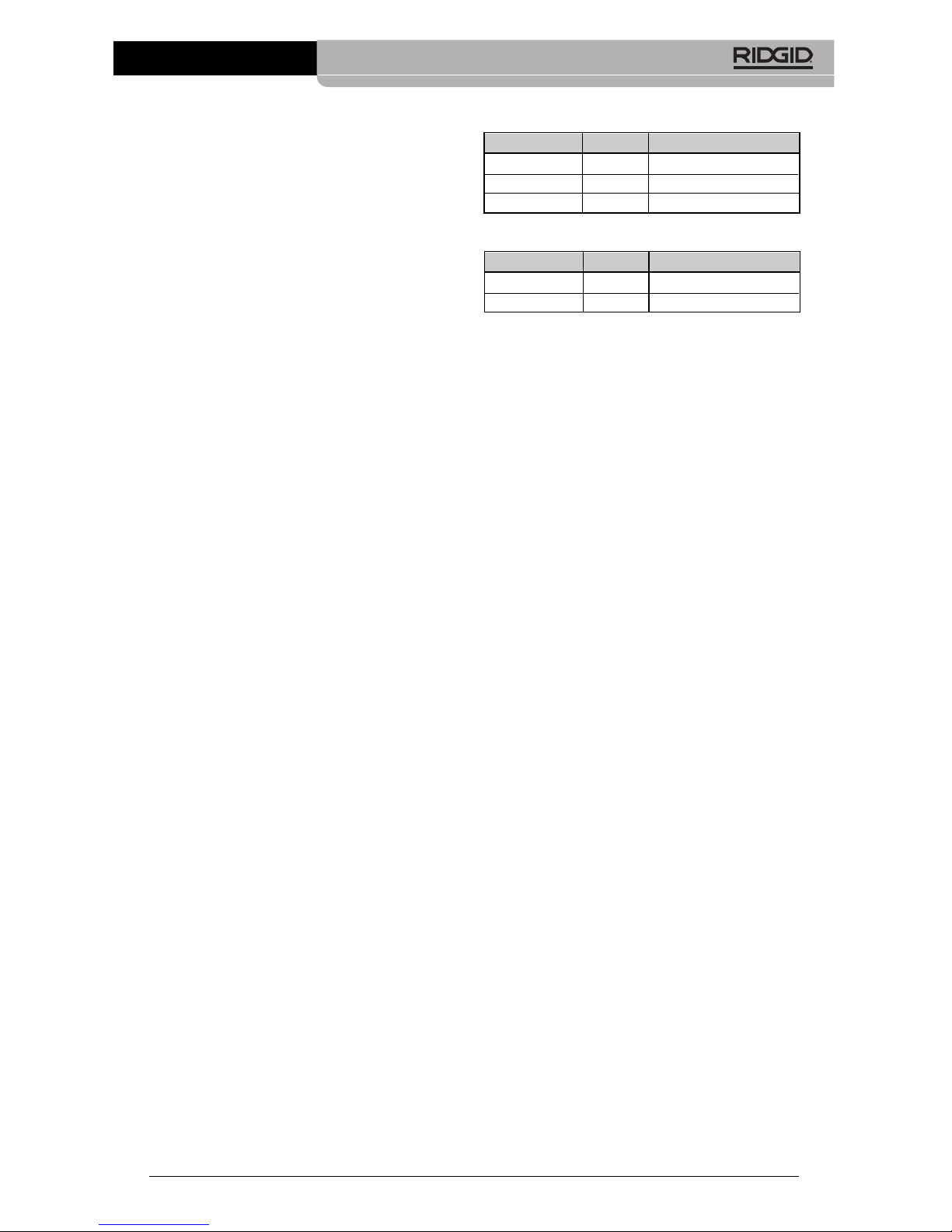
Catalog No. Size Weight
37958
1
/2" 4.46 lbs. (2,02 kg)
37963
3
/4" 4.71 lbs. (2,13 kg)
37968 1" 6.83 lbs. (3,10 kg)
Catalog No. Size Weight
48433
1
/2" 3.2 lbs. (1,45 kg)
48438
3
/4" 3.1 lbs. (1,41 kg)
Page 6
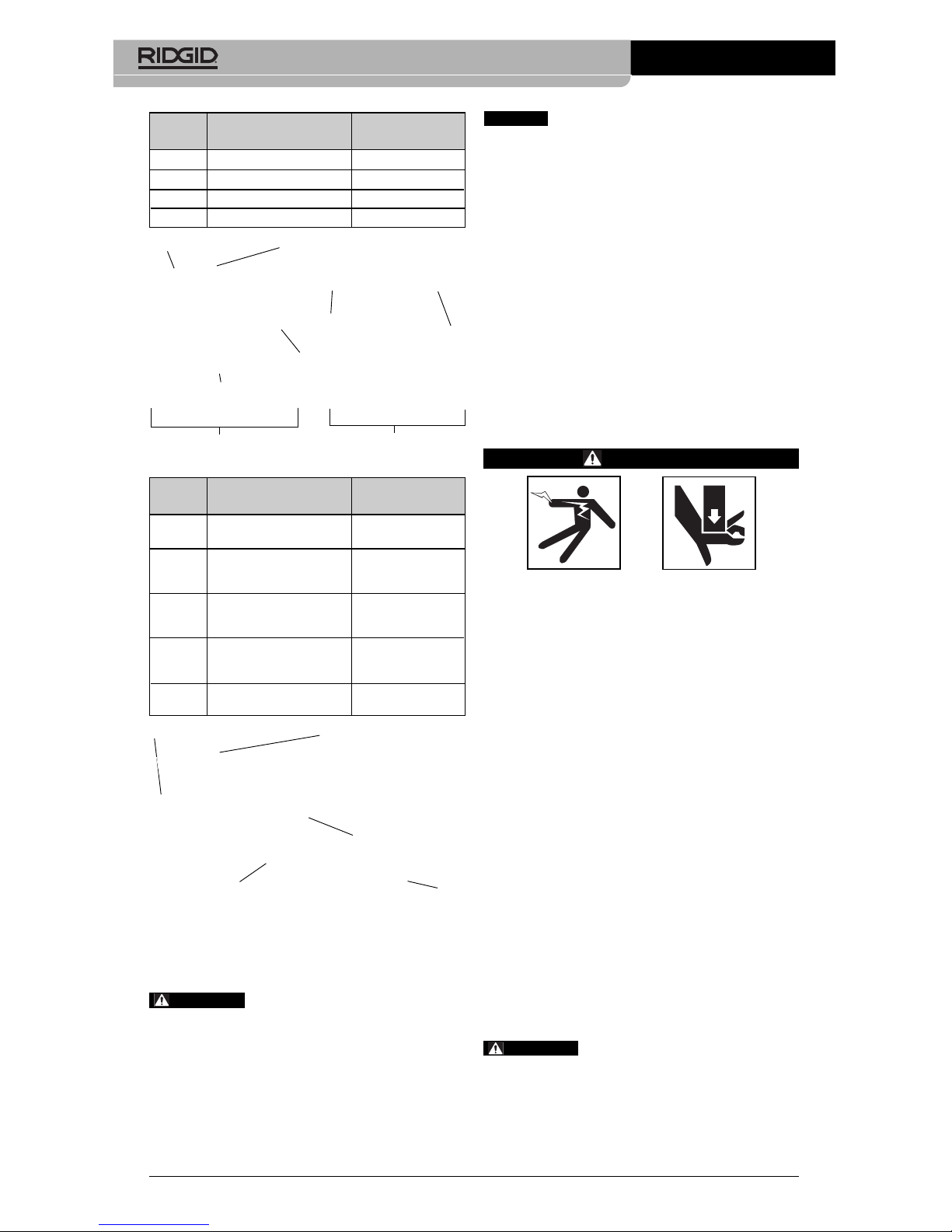
Figure 2 – MegaPress Ring and Actuator
Figure 3 – MegaPress XL Ring and Press
Booster/Z3 Actuator
Only use RIDGID Press Tools
and RIDGID press tool attachments (jaw sets,
rings, actuators, etc.) when specified by the fitting manufacturer for use with their system.
Use of incorrect press tools and/or attachments for a system can cause system leaks,
damage the press tool or attachment, void
warranties or cause severe personal injury.
Contact the fitting manufacturer for
specific information on their system, including
compatible pipe, materials, installation instructions, minimum distance between fittings, seal
material, inspection, testing, etc. Incorrect installation can cause system leaks and extensive property damage.
Contact Ridge Tool Technical Service Depart ment at (800) 519-3456 or rtctechservices@
em er son.com for a list of press fitting system
and valve manufacturers that specify RIDGID
pressing tools and attachments for their systems.
Inspecting The Press
Tool and Attachments
WARNING
Inspect your pressing tool and attachments daily and correct any problems
to reduce the risk of serious injury from
electric shock, tool and attachment failure and other causes and to prevent tool
and property damage.
1. Inspect press tool according to the specific tool operator's manual.
2. Clean any oil, grease or dirt from the
tool and attachments, especially the handles and controls. This reduces the risk of
the tool or attachment slipping from your
grip and makes inspection easier.
3. Closely inspect all pressing attachment
components (jaw sets, rings, actuators,
etc.) for any cracked, broken, worn, missing, mis-aligned or binding parts or any
other sign of damage that may prevent
proper and safe operation. Damaged parts
can cause the attachment to make incorrect pressed connections or fail during use,
and cause serious injury or property damage. If any damage is found, the attachment should be discarded and replaced.
Always discard the complete
pressing attachment. Never replace individual
components or exchange parts between assemblies. Failure to replace the entire assembly may result in component failure and serious injury.
4
085-002-881.10_REV. F
MegaPress®Fitting System
WARNING
NOTICE
WARNING
Catalog
No. Description Weight
37973 1
1
/4" MegaPress Ring 5.99 lbs (2,72 kg)
37978 1
1
/2" MegaPress Ring 6.46 lbs (2,93 kg)
37983 2" MegaPress Ring 5.77 lbs (2,62 kg)
21878 V2 Actuator 4.7 lbs (2,13 kg)
V2
Actuator
Torsion Spring
(Not Visible)
V2 Side
Plate
RIDGID V2 Actuator
V2 Actuator
Arm
V2 Actuator Spherical Tip
MegaPress Press Ring
MegaPress
Press Ring Pivot
Pin & Torsion
Spring (Not
visible)
Press Ring
Actuator Pocket
(Not Visible)
Catalog
No. Description Weight
60638 2½" to 4" MegaPress Kit
52.5 lbs (23.8 kg)
with Booster
60643 2½" MegaPress Ring For
Standard RIDGID Press 5.9 lbs (2.7 kg)
Tool & Booster
60648 3" MegaPress Ring For
Standard RIDGID Press 7.1 lbs (3.2 kg)
Tool & Booster
60653 4" MegaPress Ring
For Standard RIDGID 9.9 lbs (4.5 kg)
Press Tool & Booster
60658 Press Booster For
21.6 lbs (9.8 kg)
MegaPress XL
Handle
Actuator Arm
Actuator Spherical Tip
Press
Ring
Actuator
Pocket
Press Booster
Page 7
the Description and Specification section.
Information on clearance requirements for
various attachments can be found at the
back of the manual. Inform ation on RIDGID
Pressing Tools and oth er RIDGID press tool
attachments can be found at RIDGID.com,
or by contact ing Ridge Tool Technical Ser vice Depart ment at (800) 519-3456 or
rtctechservices@emer son.com.
Only use RIDGID Press Tools and RIDGID
press tool attachments (jaw sets, rings,
actuators, etc.) when specified by the fitting
manufacturer for use with their system.
Be sure to use the correct actuator for the
ring being used. Rings are marked to indicate the correct actuator for use with the
ring. Use of incorrect press tools and/or attachments for a system can cause system
leaks, damage the press tool and attachment or cause severe personal injury.
3. Make sure that the press tool and attachment have been inspected according to
their respective manuals or instructions.
4. Follow tool set up procedure according
to the specific press tool operator’s manual.
Mounting Attachment Into
Press Tool
1. Make sure that the press tool is unplugged or that the battery is removed
from the tool.
2. Pull the attachment mounting pin on the
press tool out. If there is already an attachment in the tool, slide it out of the
pressing tool (See Figure 4).
Figure 4 – Sliding The Attachment Out of the
Tool
3. Slide the attachment into the press tool
and fully engage the attachment mounting
pin. The press tool will not function unless
the pin is fully engaged.
Do not modify pressing attachments or use
modified attachments. A pressing attachment
component that has been welded, ground,
drilled or modified in any manner can shatter
during pressing, resulting in sharp flying objects, severe injury or death. Discard and replace damaged pressing attachments.
4. Inspect the attachment markings to make
sure that it is clearly marked as to the system and size that it is appropriate for. Do
not use an attachment that is not clearly
marked.
5. Inspect the press profile of the attachment.
If it is rusty, dirty or if there is a build up of
fitting material, clean as described in the
maintenance section. It is important to
keep the press profile clean to prevent the
formation of burrs during pressing pro cess, prevent the attachment from sticking
to the fitting and make sure that a proper
press connection is made.
6. Make sure that springs are intact and bias
the attachment in the proper direction (closed
for rings, jaws and actuators). Attach ment
should cycle freely from the fully open to
fully closed position. If needed, lubricate
pivot points with a light lubricating oil. Wipe
any excess oil from the attachment.
Tool and Work Area
Set-Up
WARNING
Set up the press tool, attachment and
work area according to these procedures
to reduce the risk of injury from electric
shock and other causes and to prevent
property damage.
1. Inspect the work to be done and determine:
• The system of fittings to be used
• The sizes of fittings to be used.
• The type of pipe to be used.
• The amount of space available for the
tool and attachments to make the
pressed connections.
2. Determine the appropriate pressing tool
and attachments for the application. See
5
085-002-881.10_REV. F
MegaPress®Fitting System
Page 8

instructions to be sure all parts are present, in place and free of dirt and debris. If
fitting parts are missing or dirty, this can
cause improper connections, leaks and
other property damage. See Figure 5.
Figure 5 – Inspection of MegaPress Fitting
Prior to Pipe Insertion
2. Check the fitting manufacturer’s instructions and mark the pipe with a permanent
marker at the appropriate distance from
the pipe end. This gives a visual reference
that the pipe has been fully inserted into
the fitting prior to pressing the connection.
See Figure 6.
Figure 6A – Marking the Pipe Before Inserting
Into Fitting Using Tape Measure
Figure 6B – Marking the Pipe Before Inserting
Into Fitting Using RIDGID
®
MegaPress®Pipe Inspection
Gauge
3. Fully insert the pipe into the fitting. Most fittings have a stop that the pipe end contacts to indicate full insertion. Other fittings do not have a stop and will allow the
pipe to fully pass through the fitting, and
are typically used in repair applications. If
there is no stop, insert the pipe so that the
Calibrating The Pressing Tool
For The Specific Pressing
Attachment
(320-E Pressing Tool Only)
The RIDGID 320-E Pressing Tool includes a
feature to help insure that complete press connections are made. To use this feature, when a
press attachment is installed on the 320-E, a
calibration cycle is done. The 320-E then compares that calibration cycle to each press connection made. If the press connection does not
match the calibration cycle, the 320-E alerts
the user that a pressing error has occurred so
that the operator can take appropriate action.
See the 320-E manual or contact Ridge Tool
Technical Service if you have any questions
regarding this feature.
Preparing The
Connection
These are generalized instructions.
Always follow the fitting manufacturer’s specific
installation instructions. Failure to follow the fitting manufacturer’s installation instructions
may lead to an improper press connection
and cause leaking connections and property
damage.
Preparing the Pipe
1. If necessary, cut the desired length of the
proper pipe for use with the fitting system. Use a pipe cutter or other method
that provides a clean cut square to the
axis of the pipe. If using a vise or other
method to hold the pipe during cutting,
make sure that the vise is far enough
from the end of the pipe not to damage
the section of pipe that is inserted into
the fitting. Scratches on the outside diameter of the pipe and deformed pipe
can cause leaks.
2. MegaPress and MegaPressG fittings require proper pipe end preparation to deburr and clean the pipe’s outside diameter. Consult fitting manufacturer’s instructions for appropriate pipe end preparation.
3. Failure to properly prepare the end of the
pipe will result in leaking connections
which can cause property damage.
Inserting the Pipe into the
Fitting
1. Inspect the fitting per the manufacturer’s
6
085-002-881.10_REV. F
MegaPress®Fitting System
NOTICE
Seal
Grip Ring
Control
Label
Separator
Ring
Page 9
Confirm that the tool and attachments have
been properly set up.
Pressing the Connection with
a Jaw Set
1. Squeeze the jaw arms to open the Jaw
set and place the open jaws around the
fitting. Allow the jaw set to close around
the fitting, making sure to align the press
profile of the Jaw set with the contour of
the fitting (See Figure 8).
Figure 8 – Opening the MegaPress Jaw set
and Placing Around Fitting
2. Confirm that the pipe is inserted to the
proper depth in the fitting as specified in
appropriate Fitting System instructions.
3. Make sure that the jaw set and pressing
tool are square to the pipe and fitting
(See Figure 9). Depress the press tool
switch. Keep fingers and hands away
from the jaw set to avoid crushing injuries in jaw set and between the jaw set
and the surroundings.
Figure 9 – MegaPress Jaw Set Square To
Fitting and Tubing
The pressing cycle takes 4-8 seconds
depending on the press tool. Once a
press cycle begins and the rollers contact
the Jaw set, the press tool will lock on and
automatically complete the press cycle.
Releasing the tool switch will not stop
mark made in the previous step is even
with the end of the fitting. In some cases,
a twisting motion during insertion makes
the process easier. Never use any lubricant unless the fitting manufacturer specifically advises to. Lubri cants can degrade
the seal and cause leaks. Pipe that is difficult to insert may be out of round or
have burrs on the pipe end, which can
damage the seal and cause leaks.
4. Make sure that the pipe is fully inserted in
the fitting and if not marked in previous
steps, mark the pipe at the end of the fitting to give a visual reference that the
pipe is fully inserted. See Figure 7.
Figure 7 – Marking the Pipe After Fully Insert -
ing Pipe
Operating Instructions
WARNING
Always wear eye protection to reduce
the risk of eye injury.
Keep your fingers and hands away from
the tool attachment during the pressing
cycle. Your fingers or hands can be
crushed, fractured or amputated in the
attachment or tool or between the attachment, work piece and other objects.
Follow operating instructions to reduce
the risk of injury from crushing and other
causes and to prevent tool damage.
Only use RIDGID Press Tools
and RIDGID press tool attachments (jaw sets,
rings, actuators, etc.) when specified by the fitting manufacturer for use with their system.
Use of incorrect press tools and/or attachments for a system can cause system leaks,
damage the press tool or attachment, void
warranties or cause severe personal injury.
7
085-002-881.10_REV. F
MegaPress®Fitting System
WARNING
Page 10

the tool once the pressing process has
begun. This ensures consistent, repeatable press connection integrity. If the tool
should malfunction, refer to the specific
press tool operator’s manual.
4. Press the jaw set jaw arms to open the
jaw set and remove from the fitting. Avoid
any sharp edges that may have formed
on fitting during pressing operation.
Pressing the Connection with
a Ring and Actuator
1. Open the appropriate Press Ring and
place squarely around the fitting. Allow
the ring to close around the fitting, making
sure to align the press profile with the
contour of the fitting. If the ring is not
properly aligned with the fitting, an improper press connection will be made
and the press ring may be damaged.
(See Figure 10.)
Figure 10 – Opening the MegaPress Ring and
Placing Around Fitting
2. Confirm that the appropriate actuator for
the ring to be pressed is in the pressing
tool (the ring will be marked with the designation of the appropriate actuator). The
correct actuator/ring combination must
be used to prevent possible injury, ring
and actuator damage, and improper press
connections. If using the 320-E Pressing
Tool, make sure that the tool and actuator
have been calibrated. If not, see the cali-
bration information in the Set Up section.
3. Squeeze the actuator arms to open the
actuator tips, place tips in ring pockets
and allow the actuator to close down and
seat into the pockets. See Figures 12A-B.
The actuator and its mating ring are designed to allow the actuator and tool to be
rotated up to ninety degrees each way
from perpendicular. Make sure that the
actuator tips are fully engaged in the ring
pockets.
MegaPress®Fitting System
085-002-881.10_REV. F
8
Misaligning actuator tip to ring pock et can damage the ring or actuator during
pressing. Make sure that the actuator tips are
fully engaged in the ring pockets. (See Figure
11.)
Figure 11 – Damaged Ring Pocket
Figure 12A – Placing Actuator Tips Into
MegaPress Ring Pockets
Figure 12B – Placing Actuator Into MegaPress
Ring Pockets At An Angle For
Additional Clearance
Do not hang the actuator and tool from
the ring. The tool and actuator could fall
from the ring and cause serious injury
or death.
4. Make sure that the ring is square to the
pipe and fitting and depress the press
tool switch. Keep fingers and hands away
from the actuator and ring to avoid crushing injuries in the attachments and between the attachments and surroundings.
For 1
1
/4", 11/2" and 2" connections, the
pressing cycle takes 4-8 seconds. For
2
1
/2", 3" and 4" connections, the pressing
cycle takes 15-24 seconds. Once a press
cycle begins and the rollers contact the
Damaged
NOTICE
Page 11

actuator, the press tool will lock on and
automatically complete the press cycle.
Releasing the tool switch will not stop
the tool once the pressing process has
begun. This ensures consistent, repeatable press connection integrity. If the tool
should malfunction, refer to the specific
press tool operator’s manual.
The MegaPress and MegaPress XL rings
are designed to fully close during the
pressing process.
5. After the pressing operation is complete,
squeeze the actuator arms to open the
actuator tips and remove from the ring.
6. Remove the ring from the fitting. Avoid
any sharp edges that may have formed
on the fitting during the pressing operation.
Inspecting The Press
Connection
1. Inspect the pressed fitting. If the fitting
is supplied with a control label by the fitting manufacturer, remove it (Refer to
Figure 5). Control labels are supplied by
the manufacturer to indicate that the fitting
has not yet been pressed. Removal of
the control label indicates to others that
the connection has been pressed.
Look for the following:
• Excessive misalignment of the pipes.
Note that a slight amount of misalignment at the pressed connection is considered normal.
• Pipes that are not fully inserted into the
fitting – double check the insertion marks
made on the pipe to see that they are
still aligned with the end of the fitting.
• Incorrect jaw or ring alignment with the
fitting contour, distorted or deformed fitting.
• Any other issues per the fitting manufac-
turer.
If any problems are found, remove the fitting and replace with properly prepared
and pressed fittings and pipe.
2. Test the system in accordance with the
system supplier’s instructions, normal
practice and local codes. The system
supplier may have specific system test
procedures to confirm the integrity of the
system.
MegaPress®Fitting System
085-002-881.10_REV. F
9
Maintenance
WARNING
Press attachments should be removed
from press tool before performing any
maintenance.
A jaw, press ring or ring actuator component that has been welded, ground,
drilled or modified in any manner can
shatter during pressing, resulting in
sharp flying objects, severe injury or
death. Discard and replace damaged
jaws, press rings or ring actuators.
1. Inspect the inside diameter of jaws and
press rings daily (Figure 13). If rusty or
dirty, clean with fine grade Scotch-Brite
®
(Scotch-Brite®is a registered trademark of
3M Company) metal polishing pads (or
equivalent), steel wool or a steel bristle
wire brush.
Do not clean pressing profile with
aggressive abrasive materials or methods,
such as emery cloth, sandpaper, grinding
wheels or rotary files. These methods may
alter critical pressing profile dimensions and
cause improper pressed connections that can
lead to leaks and extensive property damage.
2. Inspect the segment area of the Mega Press jaws/rings daily for debris or damage
that could prevent full closure and cause
out of tolerance connections. While holding
the jaw/ring open, clean the areas next to
the segment with a brush. (See Figure
13.)
Figure 13 – Cleaning Segment Area of
MegaPress Jaw
3. Pivot pins and moving points on jaws,
press rings and actuators should be
cleaned and lubricated at least once a
month with a light weight general purpose lubricating oil.
NOTICE
Page 12
4. Check return springs in press jaws, rings
and ring actuators with each use. Jaws
and ring actuators should open and close
freely with only moderate finger effort
required.
Optional Equipment
WARNING
To reduce the risk of serious injury or incorrect pressed connections, only use
accessories specifically designed and
recommended for use with MegaPress
®
Fittings such as those listed.
MegaPress®System
MegaPress Kits and Accessories
Press Tools
Machine Storage
These tools and attachments
must be kept indoors or well covered in inclement weather. Store in a locked area out of
the reach of children and people unfamiliar
with the tools. These tools can cause serious injury in the hands of untrained users.
Service and Repair
WARNING
Improper service or repair can make attachments unsafe to operate.
The “Maintenance Instructions” will take care
of most of the service needs of this machine.
Any problems not addressed by this section
should only be handled by an authorized
RIDGID service technician.
MegaPress®Fitting System
085-002-881.10_REV. F
10
No Service parts are sold for these attachments. If parts are needed, the attachment
should be discarded and a new unit purchased.
For information on your nearest RIDGID In depen dent Service Center or any service or
repair questions:
• Contact your local RIDGID distributor.
• Visit RIDGID.com to find your local RIDGID
contact point.
• Contact Ridge Tool Technical Service De partment at rtctechservices@emerson.com,
or in the U.S. and Canada call (800) 519-
3456.
Disposal
Parts of the equipment contain valuable materials and can be recycled. There are companies that specialize in recycling that may be
found locally. Dispose of the components in
compliance with all applicable regulations.
Contact your local waste management authority for more information.
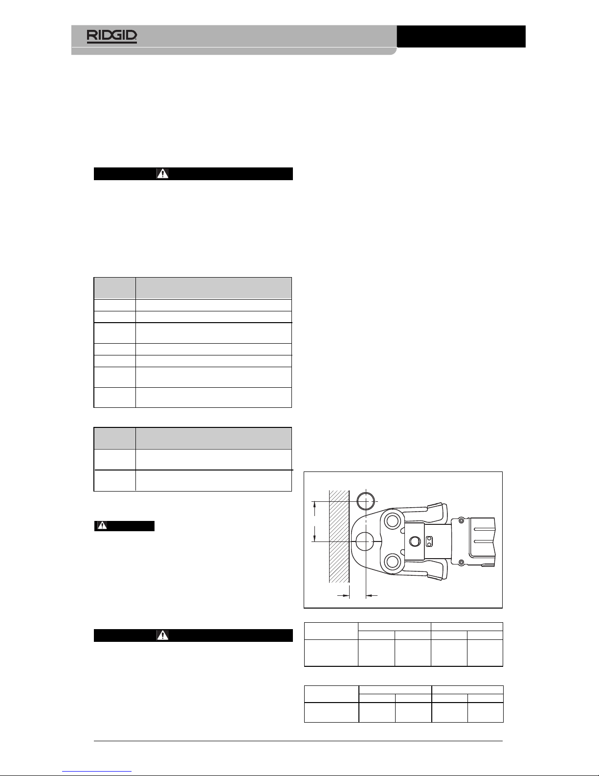
Clearance
Requirements
The following figures illustrate the clearance
requirements for the jaws and fittings and the
procedure for pressing fittings in tight quarters
with rings.
Clearance Requirements
Standard Series MegaPress Jaw Sets
Compact Series MegaPress Jaw Sets
Catalog
No. Description
48553 MegaPress Kit
1
/2" - 2"
48558 MegaPress Kit
1
/2" - 1"
48563 Carrying Case for Standard MegaPress
Tool Kits.
37993
1
/2" to 1" MegaPress Prep Tool
37988 1
1
/4" to 2" MegaPress Prep Tool
38008 Abrasive Strips for
1
/2" to 1" MegaPress
Prep Tool (Pack of 10)
38003 Abrasive Strips for 1
1
/4" to 2"
MegaPress Prep Tool (Pack of 10)
Catalog
No. Description
43348 RP 340 Battery Press Tool Kit without
Jaw Sets
43363 RP 340 Corded Press Tool Kit without
Jaw Sets
WARNING
Pipe Dia.
A (min.) B (min.)
Inches mm Inches mm
1
/2"126 25/
8
67
3
/4"1
1
/
4
32 31/
8
79
1" 1
3
/
4
45 35/
8
92
B
A
Pipe Dia.
A (min.) B (min.)
Inches mm Inches mm
1
/2"1
1
/
4
32 27/
8
73
3
/4"1
1
/
8
29 3" 76
Page 13
MegaPress®Fitting System
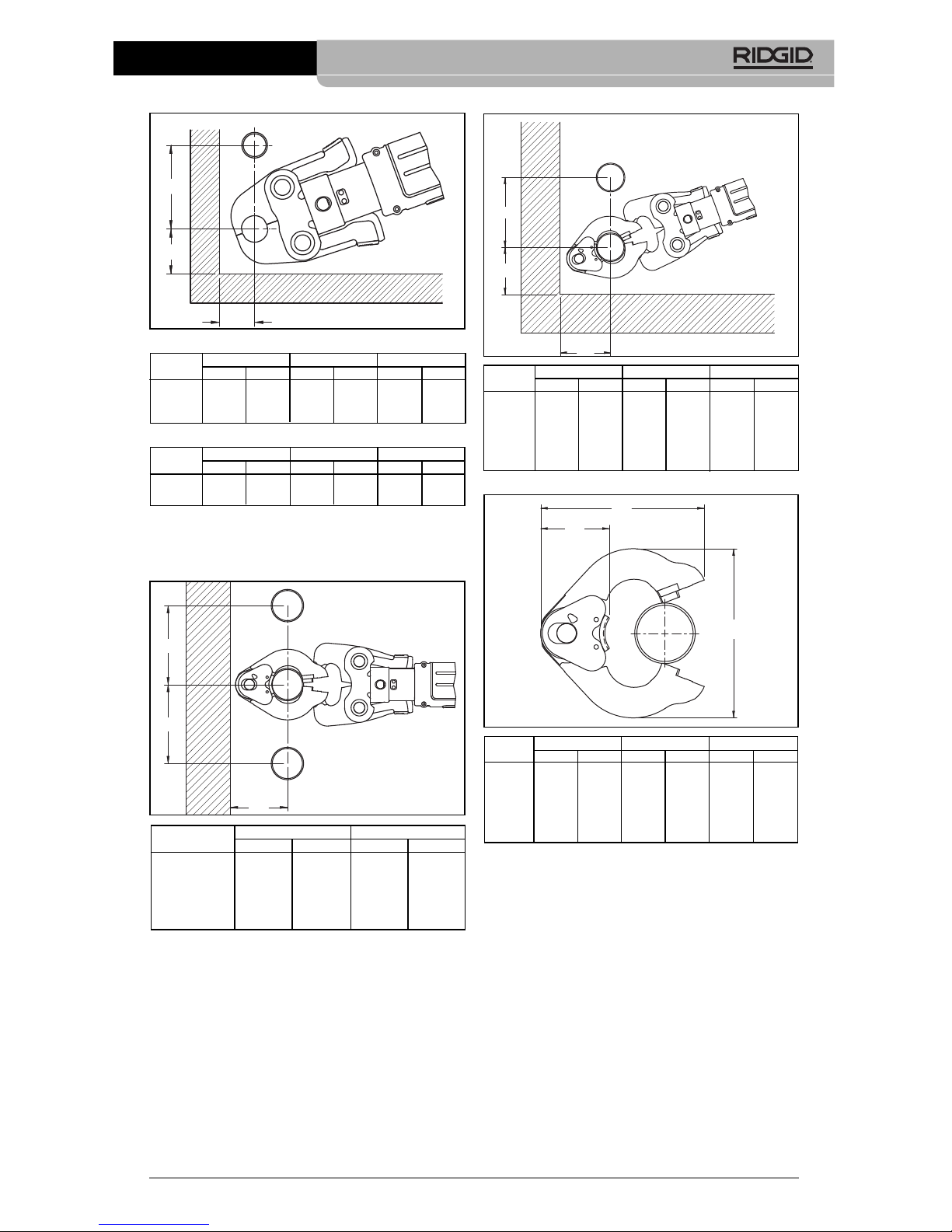
Standard Series MegaPress Jaw Sets
Compact Series MegaPress Jaw Sets
Clearance Requirements – MegaPress
Press Rings
Pipe Dia.
A (min.) B (min.) C (min.)
Inches mm Inches mm Inches mm
1
/2"11/
4
32 17/
8
48 3 76
3
/4"11/
2
38 21/
8
54 31/
2
89
1" 2 51 2
1
/
2
64 4" 101
C
A
B
085-002-881.10_REV. F
11
Pipe Dia.
A (min.) B (min.) C (min.)
Inches mm Inches mm Inches mm
1
1
/4"33/
4
95 33/
4
95 47/8124
1
1
/2"4102 4 102 51/8130
2" 4 102 4 102 5
3
/8137
21/2"41/2115 57/8150 4 100
3" 43/4120 63/4170 43/4120
4" 5
3
/8135 81/4210 51/2140
B
C
A
Pipe Dia.
A (min.) B (min.)
Inches mm Inches mm
1
1
/4"3
3
/
4
95 47/
8
124
1
1
/2"4102 51/
8
130
2" 4 102 5
3
/
8
137
21/2"4
1
/
2
115 57/
8
150
3" 43/
4
120 63/
4
170
4" 53/
8
135 81/
4
210
B
B
A
Pipe Dia.
A (min.) B (min.) C (min.)
Inches mm Inches mm Inches mm
1
/2"11/
2
38 21/
8
54 31/
8
79
3
/4"13/
8
35 21/
8
54 33/
8
86
Pipe Dia.
A (min.) B (min.) C (min.)
Inches mm Inches mm Inches mm
1
1
/4"6152 61/4159 21/
2
64
1
1
/2"6152 63/ 171 25/
8
67
2" 6 152 6
7
/8175 21/
2
64
21/2"55/8168 75/8194 21/
2
64
3" 71/2190 87/8225 21/
2
64
4" 81/2214 103/8270 25/
8
67
C
B
A
Page 14

SYMPTOM POSSIBLE REASON SOLUTION
Press connections
produced are not
complete.
Excessively large or
sharp fins present at
press joint parting
line where jaw or
ring tips come together.
Jaws or press rings
stick to fitting excessively after completing press joint.
Troubleshooting
Used wrong jaw set or press ring
for the pipe size or material.
The jaw set or ring contour was not
square to the pipe.
The jaw set or press ring has exceeded life expectations and may
have failed.
Improperly prepared pipe.
Used incorrect actuator for the ring.
Fitting material build up on jaws or
press rings in the contoured profile
area near jaw or ring tips.
Excessively worn or damaged jaws
or press rings.
Fitting material build-up on jaws or
press ring in the contoured profile
area near jaw or ring tips.
Install correct jaw set.
Redo the joint using new pipe and fitting and make sure that the jaw set
or ring is square to the fitting.
If cracked, replace old jaw set or press
ring with a new jaw set or press ring
and redo the joint using new pipe and
fitting.
Follow fitting manufacturers pipe pre paration instructions.
Use correct actuator as marked on
the ring.
Clean jaw or press ring in the contoured area using metal polishing
pads such as Scotch-Brite
®
. Refer to
Maintenance Section for instructions.
Discard jaw or press ring and replace
with new RIDGID jaw set or press
ring.
Clean jaw or press ring contour area
using metal polishing pads such as
Scotch-Brite
®
. Refer to Maintenance
Section for instructions.
MegaPress®Fitting System
085-002-881.10_REV. F
12
1. Place the press ring
around the fitting from
the front...
2. ...until the press ring
is resting on the fitting.
3. Keep the press ring
closed and rotate about
the fitting until the opening is toward the front.
4. Insert the press ring
actuator and start the
press cycle.
Tight Quarter Pressing Procedure – Pressing Rings
Page 15

Accessoires pour pince de
sertissage MegaPress
®
Système de raccordement
MegaPress
®
AVERTISSEMENT
Lisez ce manuel soigneusement
avant d’utiliser l’appareil. L’in com préhension ou le non respect des
consignes ci-devant pourrait entraîner des chocs électriques, des
incendies et/ou de graves blessures
corporelles.
Page 16

14
085-002-881.10_REV. F
Système de raccordement MegaPress
®
Table des matières
Symboles de sécurité ..................................................................................................15
Consignes de sécurité spécifiques
Sécurité de la sertisseuse.............................................................................................15
Description et caractéristiques techniques
Description ....................................................................................................................16
Caractéristiques techniques..........................................................................................16
Inspection préalable de la sertisseuse et accessoires ................................................17
Préparation de l’appareil et des lieux
Montage des outils de sertissage .................................................................................18
Calibrage de la pince de sertissage en fonction des accessoires utilisés
(Pince de sertissage 320-E uniquement)......................................................................19
Préparation des raccords
Préparation du tuyau.....................................................................................................19
Introduction du tuyau dans le raccord ...........................................................................19
Mode opératoire
Sertissage des raccords à l’aide de mâchoires ............................................................20
Sertissage des raccords à l’aide de bagues et actionneur ...........................................21
Contrôle des sertissages................................................................................................22
Consignes d’entretien.....................................................................................................22
Accessoires
Système MegaPress .....................................................................................................23
Protection du matériel.....................................................................................................23
Révisions et réparations .................................................................................................24
Recyclage .........................................................................................................................24
Tableaux des refuites minimales....................................................................................24
Dépannage .......................................................................................................................26
Déclaration de conformité CE....................................................recto de la page de garde
Garantie à vie ...............................................................................................
Page de garde
*Traduction de la notice originale
Page 17

Système de raccordement MegaPress
®
085-002-881.10_REV. F
15
Symboles de sécurité
Des symboles et mots clés spécifiques, utilisés à la fois dans ce mode d’emploi et sur l’appareil
lui-même, servent à signaler d’importants risques de sécurité. Ce qui suit permettra de
mieux comprendre la signification de ces mots clés et symboles.
Ce symbole sert à vous avertir aux dangers physiques potentiels. Le respect des consignes qui
le suivent vous permettra d’éviter les risques de blessures graves ou mortelles.
Le terme DANGER signifie une situation dangereuse potentielle qui, faute d’être
évitée, provoquerait la mort ou de graves blessures corporelles.
Le terme AVERTISSEMENT signifie une situation dangereuse potentielle qui,
faute d’être évitée, serait susceptible d’entraîner la mort ou de graves blessures
corporelles.
Le terme ATTENTION signifie une situation dangereuse potentielle qui, faute d’être
évitée, serait susceptible d’entraîner des blessures corporelles légères ou modérées.
Le terme AVIS IMPORTANT signifie des informations concernant la protection
des biens.
Ce symbole indique la nécessité de lire le manuel soigneusement avant d’utiliser le matériel.
Le mode d’emploi renferme d’importantes informations concernant la sécurité d’utilisation du
matériel
Ce symbole indique la nécessité de porter des lunettes de sécurité étanches ou à visières lors
de la manipulation ou utilisation de l’appareil afin de limiter les risques de blessure oculaire.
Ce symbole indique un risque d’écrasement des mains, des doigts et autres membres.
Ce symbole indique un risque de choc électrique.
de l’actionneur durant le cycle de sertissage. Les doigts et les mains peuvent être
écrasés, fracturés ou amputés en cas de
prise entre les mâchoires, les bagues de
sertissage ou l’actionneur, voire entre ces
éléments et tout autre objet.
• Ne jamais tenter de réparer une mâ-
choire, une bague ou un actionneur endommagé. Les mâ-choires, bagues et ac-
tionneurs qui ont été soudés, meulés, percés ou modifiés d’une manière quelconque
risqueraient d’éclater en cours de sertissage et provoquer de graves lésions corporelles. Le cas échéant, remplacez systématiquement les deux mâchoires en même
temps. Ne jamais remplacer un seul élément, sauf dans le cas d’un ressort de rappel endommagé. Consultez les services
techniques de la Ridge Tool Company pour
la disponibilité des pièces de rechange.
• Familiarisez-vous avec le manuel ci-
présent, les consignes du fabricant des
raccords et celles de tout autre matériel
employé avant d’utiliser cette sertisseuse. Le non-respect de l’ensemble des
consignes applicables augmenterait les
risques de dégâts et/ou de grave blessure
corporelle.
Consignes de sécurité
spécifiques
AVERTISSEMENT
Cette section contient d’importantes informations sur ce type d’appareil parti culier.
Afin de limiter les risques de choc électrique et d’accident grave, lisez les précautions d’emploi ci-après soigneusement avant de vous servir des outils de
sertissage.
CONSERVEZ CES INSTRUCTIONS !
Gardez ce manuel avec l’appareil afin qu’il
puisse servir à tout utilisateur éventuel.
Sécurité de la sertisseuse
• Ne montez que des outils de sertissage
RIDGID sur une sertisseuse RIDGID
®
.
L’emploi de l’appareil ou la modification de
ses mâchoires à d’autres fins pourrait endommager la sertisseuse et/ou ses mâchoires et augmenterait les risques de grave
blessure corporelle.
• Eloignez vos doigts et vos mains des
mâchoires, des bagues de sertissage et
AVIS IMPORTANT
DANGER
AVERTISSEMENT
ATTENTION
Page 18

Système de raccordement MegaPress
®
085-002-881.10_REV. F
16
MegaPressG pour tuyaux acier d’un diamètre
nominal (NPS) de
1
/2", 3/4" et 1". Chaque diamètre de tuyau utilise ses mâchoires spécifiques. Les mâchoires et pinces de sertissage
doivent être tenues à l’équerre du raccord et
tuyau concernés.
Ces mâchoires sont disponibles en série
Standard pour sertisseuses RIDGID telles
que les CT-400, 320-E, RP 330 et RP 340,
ainsi que pour les sertisseuses de la série
Compact telles que les 100-B, RP 210-B, RP
200-B, RP 240 et RP 241.
Mâchoires MegaPress série Standard
Mâchoires MegaPress série Compact
Figure 1 – Mâchoires MegaPress (série
Standard)
Bagues MegaPress
Les bagues MegaPress servent au sertissage
mécanique des raccords MegaPress et
MegaPressG pour tuyaux acier d’un diamètre
nominal (NPS) de 1
1
/4", 11/2" et 2". Chaque diamètre de tuyau utilise une bague spécifique.
Les bagues de 1
1
/4" à 2" ne peuvent être utilisées qu’avec les actionneurs V2 des sertisseuses de la série Standard.
Bagues MegaPress XL
Les bagues MegaPress XL sont prévues pour
le sertissage des raccords sur tuyaux de 2
1
/2",
3" et 4" de diamètre. Chaque diamètre de
tuyau utilise une bague spécifique. Les bagues
MegaPress XL ne peuvent être utilisées
qu’avec un actionneur de type RIDGID
®
Z3, tel
que le Press Booster.
Si les bagues de sertissage MegaPress et
Le choix des matériaux et
des techniques de raccordement reste la responsabilité du concepteur et/ou de l’installa teur du réseau. Avant toute installation, il convient d’évaluer soigneusement les conditions
d’exploitation du réseau, notamment au niveau
de son milieu chimique et des températures d’exploitation anticipées.
Au besoin, une copie de la Déclaration de
conformité CE (890-011-320.10) accompagnera ce manuel.
En cas de questions concernant ce produit
RIDGID
®
:
– Consultez votre distributeur RIDGID.
– Consultez le site RIDGID.com pour lo-
caliser les représentants RIDGID les
plus proches.
– Consultez les services techniques Ridge
Tool par mail adressé à rtctechservices
@emerson.com, ou, à partir des EtatsUnis et du Canada, en composant le
(800)519-3456.
Description et
caractéri stiques
techniques
Description
Utilisés avec une sertisseuse RIDGID appropriée, les outils de sertissage des systèmes
MegaPress
®
et MegaPressG®permettent le
ser tissage mécanique des raccords MegaPress
afin d’assurer l’étanchéité permanente des
conduites d’eau ou de gaz. MegaPress et
MegaPressG sont des marques déposées par
la société Viega GmbH & Co. Il s’agit simplement d’appuyer sur la gâchette de la sertisseuse pour lancer le cycle de sertissage mu par
son moteur électrique et sa pompe hydraulique
qui, elle, envoi du fluide hydraulique dans le
cylindre de l’appareil. Ceci a pour effet de faire
avancer les galets de la sertisseuse contre
l’outil de sertissage qui, lui, déforme le raccord spécialement conçu sous plusieurs milliers
de livres de pression.
A partir du moment où l’on appui sur la gâ chette, le cycle de sertissage ne dure que de 4
à 8 secondes. Lorsque l’appareil entame un
cycle de sertissage, il continuera automatiquement jusqu’à sa fin.
Mâchoires MegaPress
Les mâchoires MegaPress servent au sertissage mécanique des raccords MegaPress et
Réf. Catalogue Diamètre Poids
37958
1
/2" 4,46 livres (2,02 kg)
37963
3
/4" 4,71 livres (2,13 kg)
37968 1" 6,83 livres (3,10 kg)
AVIS IMPORTANT
Réf. Catalogue Diamètre Poids
48433
1
/2" 3.2 lbs. (1,45 kg)
48438
3
/4" 3.1 lbs. (1,41 kg)
Page 19

Système de raccordement MegaPress
®
085-002-881.10_REV. F
17
MegaPress XL doivent toujours se trouver perpendiculaires au tuyau, la rotule créée par le
téton de l’actionneur et l’évidement de la bague
leur permet un pivotement maximal de 90°
dans chaque sens. Cela peut faciliter leur utilisation dans les endroits restreints. Les bagues
sont marquées du type d’actionneur devant
être utilisé.
Figure 2 – Bague et actionneur MegaPress
Figure 3 – Bague MegaPress XL et actionneur
type Z3 Press Booster
N’utilisez les sertisseus es et outils de sertissage RIDGID (mâchoires,
bagues de sertissage, actionneurs, etc.) que
lorsque ceux-ci ont été stipulés par le fabricant
du système de raccordement utilisé. L’emploi
d’une sertisseuse ou d’outils inadaptés pourrait
entraîner des fuites, endommage la sertisseuse et ses outils, annuler les garanties ou
provoquer de graves lésions corporelles.
Renseignez-vous auprès
du fabricant des raccords pour tous détails applicables (compatibilité des tuyaux, matériaux,
consignes d’installation, distance minimale entre
raccords, composition des joints, méthodes de
contrôle d’étanchéité, mises à l’épreuve, etc.).
Une installation inadaptée risque de provoquer
des fuites et d’importants dégâts matériels.
Consultez les services techniques de Ridge
Tool en composant le (800) 519-3456 ou par
mail à rtctechservices@emerson.com pour la
liste des fabricants de rac cords et de vannes
qui stipulent les sertisseuses et outils de sertissage RIDGID.
Contrôle préalable
de la sertisseuse et des
outils de sertissage
AVERTISSEMENT
Examinez la sertisseuse et ses outils de
sertissage au quotidien afin de corriger
toute anomalie éventuelle et limiter les
risques blessure par choc électrique, défaillance du matériel ou autres causes, et
d’éviter la détérioration de l’appareil,
ainsi que les dégâts matériels.
1. Examinez la sertisseuse selon les consignes de son manuel.
2. Eliminez toutes traces de crasse et de
cambouis de l’appareil, notamment au
niveau des poignées et commandes,
ainsi que des outils de sertissage. Cela
limitera les risques de perte de contrôle
de l’appareil et facilitera son inspection.
3. Examinez soigneusement l’ensemble des
outils de sertissage (mâchoires, bagues de
sertissage, actionneurs, etc.) pour signes
de bris, fissuration, usure, absence, mau-
Réf.
catalogue Description Poids
37973 Bague MegaPress Ø 1
1
/4" 5,99 livres (2,72 kg)
37978 Bague MegaPress Ø 1
1
/26,46 livres (2,93 kg)
37983 Bague MegaPress Ø 2" 5,77 livres (2,62 kg)
21878 Actionneur V2 4,7 livres (2,13 kg)
Ressort
de rappel
de l’actionneur
V2 (caché)
Platine
latérale de
l’actionneur
V2
RIDGID V2 Actuator
Bras de
l’actionneur V2
Pinces sphériques
de l’actionneur V2
MegaPress Press Ring
Axe et ressort
de rappel de
bague de
sertissage
MegaPress
Dépression de
pince d’actionneur
de la bague de
sertissage
(caché)
AVIS IMPORTANT
AVERTISSEMENT
Réf.
catalogue Description Poids
60638 Kit MegaPress Ø 2½" à 4"
52,5 livres (23,8 kg)
avec Booster
60643 Bague MegaPress Ø 2½"
pour sertisseuse RIDGID 5,9 livres (2,7 kg)
standard et Booster
60648 Bague MegaPress Ø 3"
pour sertisseuse RIDGID 7,1 livres (3,2 kg)
standard et Booster
60653 Bague MegaPress Ø 4"
pour sertisseuse RIDGID 9,9 livres (4,5 kg)
standard et Booster
60658 Press Booster pour
21,6 livres (9,8 kg)
MegaPress XL
Poignée
Mâchoire de l’actionneur
Embout sphérique de
l’actionneur
Evidement
de la
bague
Press Booster
Page 20

Système de raccordement MegaPress
®
085-002-881.10_REV. F
18
Préparation de
l’appareil et du chantier
AVERTISSEMENT
Afin de limiter les risques de blessure
par choc électrique ou autres causes et
de limiter les risques de dégâts matériels
potentiels, respectez les consignes suivantes visant la préparation des lieux, de la
sertisseuse et des outils de sertissage.
1. Examinez les travaux à effectuer afin de
déterminer :
• Le type de système de raccordement
nécessaire
• Les sections de raccords nécessaires
• Le type de tuyau à prévoir
• La suffisance de refuite disponible au-
tour des tuyaux pour accommoder la
sertisseuse et ses outils afin d’effectuer
les sertissages.
2. Sélectionnez les types de sertisseuse et
d’outils de sertissage appropriés en vous
reportant au chapitre Des cription et carac-
téristiques techniques. Les refuites minimales nécessaires aux divers types d’outils
de sertissage se trouvent à la fin du ma nuel. Des renseignements concernant les
sertisseuses RIDGID et autres outils de
sertissage RIDGID peuvent être obtenus
sur le site RIDGID.com, en appelant les
services techniques RIDGID au (800) 5193456 ou par mail adressé à rtctechservices@emer son.com.
N’utilisez les sertisseuses et outils de sertissage RIDGID (mâchoires, bagues, actionneurs, etc.) que lorsque ceux-ci sont
spécifiés par le fabricant des raccords du
système utilisé. Assurez-vous que l’ac tion neur correspond bien au type de bague
utilisé. Le type d’actionneur approprié est
indiqué sur chaque bague. L’emploi de
sertisseuses et/ou d’outils de sertissage
mal adaptés risque de compromettre l’étanchéité du système, endommager la sertisseuse et les outils, voire entraîner de
graves lésions corporelles.
3. Assurez-vous que la sertisseuse et les
outils de sertissage ont bien été examinés
selon les consignes correspondan tes.
vais alignement, grippage ou autre anomalie qui pourrait compromettre le bon fonctionnement et la sécurité de l’appareil. La
moindre défaillance risque de nuire à l’étanchéité des raccords et provoquer de
graves lésions corporelles ou d’impor tants dégâts matériels. Tout élément défectueux doit être recyclé et immédiatement remplacé.
Recyclez systémati que ment l’outil défectueux au complet. Ne jamais
remplacer d’éléments individuels ou tenter
de les associer à ceux d’un autre ensemble.
Le remplacement intégral de l’outil limitera
les risques de défaillance de l’appareil et de
graves lésions corporelles.
Ne jamais modifier les outils de sertissage ou
utiliser des outils de sertissage déjà modifiés.
Tout élément soudé, meulé, percé ou modifié
d’une manière quelconque risque d’éclater en
cours d’utilisation et de provoquer des lésions
corporelles potentiellement mortelles. Recyclez
et remplacez systématiquement tout outil de
sertissage endommagé.
4. Assurez-vous de la lisibilité de l’estampe
de l’outil et de sa compatibilité avec le
type et la section des raccords utilisés. Ne
jamais utiliser un outil de sertissage dont
l’estampe est illisible.
5. Examinez la surface d’attaque de l’outil de
sertissage. En présence de rouille, de
crasse ou de dépôts métalliques, nettoyez-la selon les consignes du chapitre
Entretien. La surface d’attaque de l’outil
de sertissage doit toujours rester propre
afin d’éviter la formation de bavures en
cours de sertissage, d’éviter que l’outil
se colle au raccord, et d’assurer l’étanchéité du raccord.
6. Assurez-vous que les ressorts de rappel sont intacts et correctement installés
(fermés pour les bagues, les mâchoires
et les actionneurs). L’outil doit pouvoir
aller librement de sa position ouverte à sa
position fermée. Au besoin, lubrifiez ses
articulations à l’aide d’une huile minérale
légère, puis essuyez toutes traces d’huile
résiduelle.
AVERTISSEMENT
Page 21

Système de raccordement MegaPress
®
085-002-881.10_REV. F
19
pourrait compromettre l’étanchéité du réseau et
provoquer d’importants dégâts matériels.
Préparation des tuyaux
1. Coupez le tuyau approprié à la longueur
voulue à l’aide d’un coupe-tubes ou autre
moyen assurant une coupe franche et d’équerre. Lors de sa coupe, assurez-vous
que tout dispositif de maintien du tuyau
(étau ou autre) se trouve assez loin de
l’extrémité du tuyau pour ne pas endommager sa surface d’in sertion. La moindre
égratignure ou déformation de la surface
externe du tuyau risque de compromettre
l’étanchéité du raccord.
2. Le bon fonctionnement des raccords
MegaPress et MegaPressG dépend de
l’ébarbage et nettoyage externe appropriés des embouts de tuyau. Consultez le
fabricant des raccords pour le type de
tuyau et la méthode de préparation applicables.
3. Une mauvaise préparation de l’extrémité
du tuyau compromettrait l’étanchéité du
raccord au point de provoquer des dégâts
matériels.
Insertion du tuyau dans
le raccord
1. En vous reportant aux indications du fabricant et à la Figure 5 assurez-vous de l’in-
tégralité du raccord, de son assemblage
approprié et de sa propreté. L’ab sence
ou l’encrassement d’un ou plu sieurs éléments constitutifs du raccord risquerait
de compromettre son étanchéité et provoquer des dégâts matériels
Figure 5 – Inspection du raccord MegaPress
avant l’insertion du tuyau
2. En vous reportant aux indications du fabricant et à la Figure 6, tracez un repère
sur le tuyau pour marquer la profondeur
d’insertion nécessaire à partir de son ex-
4. Préparez le matériel selon les consignes
du manuel de la sertisseuse utilisée.
Montage des outils de
sertissage
1. Assurez-vous que la sertisseuse est dé branchée ou que sa pile a été retirée.
2. Retirez la broche de montage de la sertisseuse. En présence d’un outil de sertissage existant, retirez l’outil de la sertisseuse (Figure 4).
Figure 4 – Retrait d’un outil de sertissage
3. Enfilez l’outil de sertissage dans la sertisseuse, puis réintroduisez la broche de
montage à fond. La sertisseuse ne fonctionnera que si sa broche de montage est
complètement engagée.
Calibrage de la sertisseuse en
fonction de l’accessoire de
sertissage utilisé (sertisseuse
320-E uniquement)
La sertisseuse RIDGID 320-E est équipée
d’un dispositif qui permet de contrôler la parfaite étanchéité des raccords sertis. Ceci demande que l’on effectue un cycle de calibrage
lors du montage d’un nouvel accessoire sur la
sertisseuse. La 320-E comparera chaque sertissage de raccord successif à ce cycle de
calibrage. Si le sertissage effectué ne correspond pas au calibrage initial, la 320-E avertit
l’utilisateur pour qu’il puisse prendre les
mesures nécessaires.
Reportez-vous au manuel de la 320-E ou
consultez les services techniques de Ridge
Tool en cas de questions visant ce dispositif.
Préparation des
raccords sertis
Il s’agit ici de consignes
génériques. Respectez systématiquement les
consignes spécifiques du fabricant des raccords pour les travaux envisagés. Toute dérivation aux instructions du fabricant des raccords
AVIS IMPORTANT
Joint d’étanchéité
Anneau de serrage
Etiquette de
contrôle
Anneau de
séparation
Page 22

Système de raccordement MegaPress
®
085-002-881.10_REV. F
20
Figure 7 – Repérage du tuyau après son
inser tion
Mode opératoire
AVERTISSEMENT
Portez systématiquement une protection oculaire afin de limiter les risques de
blessure oculaire.
Eloignez vos doigts et vos mains des
outils de sertissage durant le cycle de
sertissage. L’appareil est susceptible
d’écraser, de fracturer ou d’amputer tout
membre qui se trouve entre lui et tout
autre objet.
Respectiez les consignes d’utilisation
afin de limiter les risques de blessure
corporelle et de détérioration de l’ap pareil.
N’utilisez les ser tisseuses et outils de sertissage RIDGID (mâchoires, bagues de sertissage, actionneurs,
etc.) que lorsque ceux-ci ont été stipulés par le
fabricant du système de raccordement utilisé.
L’emploi d’une sertisseuse ou d’outils inadaptés
pourrait entraîner des fuites, endommage la
sertisseuse et ses outils, annuler les garanties
ou provoquer de graves lésions corporelles.
Vérifiez le bon assemblage de la sertisseuse
et des outils de sertissage.
Sertissage des raccords à
l’aide de mâchoires
1. Comprimez les bras de l’outil afin d’ouvrir
ses mâ-choires et les enfiler autour du
raccord. Laissez les mâchoires se refermer sur le raccord en vous assurant que
le profil des mâchoires s’aligne bien sur
celui du raccord (Figure 8).
trémité. Cela laissera une indication visuelle de l’insertion complète du tuyau
avant son sertissage.
Figure 6A – Repérage de la profondeur d’inser-
tion du tuyau à l’aide d’un mètre à
ruban
Figure 6B – Repérage de la profondeur d’inser-
tion du tuyau à l’aide d’une jauge
de contrôle RIDGID
®
MegaPress
®
3. Introduisez le tuyau dans le raccord jus qu’à buter. La majorité des raccords sont
pourvus d’une butée qui permet d’assurer l’insertion complète du tuyau. Ceux
qui ne le sont pas sont généralement
destinés aux travaux de réparation et permettent au tuyau de les traverser de part
en part. En l’absence de butée, introduisez le tuyau jusqu’au repère laissé sur
lui lors de l’étape précédente. Dans certains cas, un léger mouvement rotatif facilitera l’insertion du tuyau. Sauf indication
contraire du fabricant des raccords, ne
jamais utiliser de lubrifiants. Certains lubrifiants peuvent dé tériorer le joint d’étanchéité et provoquer des fuites. Une insertion particulièrement difficile peut signaler un faux rond ou mauvais ébar bage
du tuyau qui pourrait endommager le joint
d'étanchéité du raccord et provoquer des
fuites.
4. Assurez-vous de l’insertion complète du
tuyau, et s’il n’a pas été marqué lors de
l’étape précédente, marquez l’extrémité
du raccord afin de laisser une référence
visuelle de son enfoncement (Figure 7).
AVERTISSEMENT
Page 23

Système de raccordement MegaPress
®
085-002-881.10_REV. F
21
Figure 8 – Ouverture et positionnement des
mâchoires MegaPress sur le raccord
2. Vérifiez la profondeur d’insertion du tuyau
dans le raccord selon les consignes du
système de raccordement utilisé.
3. Assurez-vous que la sertisseuse et les
mâchoires sont bien perpendiculaires au
tuyau et au raccord (Figure 9). Appuyez
sur la gâchette de la sertisseuse, tout en
éloignant vos doigts et vos mains des
mâchoires afin d’éviter leur écrasement
entre les mâchoires et entre l’outil et les
objets environnants.
Figure 9 – Mâchoires MegaPress tenues à l’é-
querre du raccord et du tuyau
Le cycle de sertissage peut durer entre 4
et 8 secondes selon le type d’outil de
sertissage utilisé. Une fois que le cycle de
sertissage est entamé et que les galets de
la sertisseuse s’engagent contre les mâ choires, la sertisseuse se verrouille automatiquement jusqu’à la fin du cycle de
sertissage. Le fait de lâcher la gâchette
n’arrêtera pas la sertisseuse une fois le
cycle entamé. Cela sert à assurer la constance et l’intégrité des sertissages à
répétition. En cas de défaillance de la
sertisseuse, veuillez consulter le manuel
de l’appareil.
4. Comprimez à nouveau les bras de l’outil
pour libérer les mâchoires et les retirer du
raccord. Evitez les bavures tranchantes
qui auraient pu se former sur le raccord
durant son sertissage.
Sertissage des raccords à
l’aide d’une bague et d’un
actionneur
Figure 10 – Ouverture de la bague MegaPress
et engagement sur raccord
1. Ouvrez la bague de sertissage ap pro priée et en gagez-la bien d’équerre sur
le raccord. Laissez la bague se refermer
autour du raccord, tout en vérifiant que
son profil s’aligne bien sur celui du raccord. Un mauvais alignement de la bague
produirait un mauvais sertissage et pourrait endommager la bague elle-même
(Figure 10).
2. Assurez-vous que la sertisseuse est équi pée de l’actionneur approprié, tel qu’il est indiqué sur la bague elle-même. L’actionneur
et la bague doivent être assortis afin d’éviter
d’éventuelles blessures corporelles, d’éviter
d’endom mager la bague et l’action neur,
et d’as surer l’étanchéité des raccords. Lors
de l’utilisation d’une sertisseuse type 320E, assurez-vous que cette dernière et l’ac tion neur ont été correctement calibrés au
préalable. Sinon, reportez-vous au chapitre
Préparation pour les modalités de calibrage applicables.
3. Comprimez les bras de l’actionneur afin
d’ouvrir ses pinces et les engager dans
les dépressions correspondantes de la
bague de sertissage. Relâchez les bras
de l’actionneur pour que les pinces se
referment sur les dépressions de la bague
(Figures 12A et 12B). L’actionneur et sa
bague sont conçus de telle manière que
l’actionneur et la sertisseuse peuvent être
déportés de 90° dans les deux sens par
rapport à la perpendiculaire. Assurezvous que les pinces de l’actionneur sont
complètement enga gées dans les dépressions de la bague.
Page 24

Système de raccordement MegaPress
®
085-002-881.10_REV. F
22
Le mauvais alignement
des pinces de l’actionneur par rapport aux
dépressions de la bague risque d’endommager à la fois la bague et l’actionneur en
cours de sertissage. Assurez-vous que les
pinces de l’actionneur sont engagées à fond
dans les dépressions de la bague (Figure 11).
Figure 11 – Déformation au niveau de la dé-
pression de bague
Figure 12A – Engagement des pinces d’ac-
tionneur dans les dépressions
de bague
Figure 12B – Engagement à 90° de l’action-
neur dans la bague MegaPress
en cas de manque de refuite
Ne jamais laisser pendre l’actionneur et la
sertisseuse depuis une bague de sertissage. La sertisseuse et l’actionneur risqueraient de tomber et provoquer de
graves blessures, voire des blessures
mortelles.
4. Assurez-vous que la bague de sertissage
est parfaitement positionnée sur le raccord, puis appuyez sur la gâchette de la
sertisseuse. Eloignez vos doigts et vos
mains de l’actionneur et de la bague afin
d’éviter leur écrasement éventuel entre les
mâchoires de l’outil et/ou celui-ci et des
objets environnants.
La durée du cycle de sertissage sera de 4
à 8 secondes pour les raccords de 1
1
/4",
1
1
/2" et 2" de diamètre, et de 15 à 24 sec-
ondes pour les raccords de 2
1
/2", 3" et 4"
de diamètre. Une fois que le cycle de sertissage est entamé et que les galets de la
sertisseuse s’engagent contre l’action neur, la sertisseuse se verrouille automatiquement jusqu’à la fin du cycle de sertissage. Le fait de lâcher la gâch ette n’arrêtera pas la sertisseuse une fois le cycle
entamé. Cela sert à assurer l’homogénéité
et l’intégrité des sertissages à répétition.
En cas de défaillance de la sertisseuse,
veuillez consulter le manuel de l’appareil.
Les bagues MegaPress et MegaPress
XL doivent être complètement fermées
durant le processus de sertissage.
5. Une fois le cycle de sertissage terminé,
comprimez les bras de l’actionneur pour
libérer et retirer la bague.
6. Retirez la bague de sertissage du raccord en évitant d’éventuelles bavures tranchantes qui auraient pu se former en cours
d’opération.
Contrôle des sertissages
1. Examinez le sertissage. Si le raccord est
pourvu d’une étiquette de contrôle, retirez-la (Figure 5). La présence d’une éti-
quette de contrôle indique que le raccord n’a pas encore été serti. Le retrait de
l’étiquette de contrôle d’un raccord permet
d’indiquer à autrui que le raccord en
question est déjà serti.
Contrôlez les points suivants :
• Désalignement excessif des tuyaux au
droit du raccord. A noter qu’une légère
déviation au droit du raccord est considérée normale.
• Déboîtement partiel des tuyaux. Vérifiez
les repères d’insertion des tuyaux pour
vous assurer qu’ils affleurent toujours
l’extrémité du raccord.
• Raccord déformé suite à un mauvais
alignement de l’outil de sertissage.
• Toute autre anomalie potentielle sig-
nalée par le fabricant des raccords.
En cas d’anomalie, il sera nécessaire de
retirer le raccord et de prévoir une nou-
Déformation
AVIS IMPORTANT
Page 25

Système de raccordement MegaPress
®
085-002-881.10_REV. F
23
velle préparation des tuyaux et un nouveau raccord.
2. Eprouvez le système selon les consignes
du fournisseur du système de raccordement, des règles de l’art et de la réglementation en vigueur. Le cas échéant, il
conviendra d’appliquer les consignes particulières du fournisseur en matière des
épreuves d’étanchéité du réseau.
Consignes d’entretien
AVERTISSEMENT
Tout accessoire de sertissage doit être
retiré de la sertisseuse avant son entretien.
Tout élément de mâchoire de bague de
sertissage ou d’actionneur qui aurait été
soudé, meulé, percé ou modifié de ma nière quelconque risquerait d’éclater en
cours d’opération et projeter des débris
tranchants susceptible de provoquer des
lésions potentiellement mortelles. Eli mi nez et remplacez toutes mâchoires,
bagues de sertissage et actionneurs de
bague endommagés.
1. Examinez les surfaces d’attaque des mâchoires et des bagues de sertissage au
quotidien (Figure 13). En présence de
rouille ou de crasse, nettoyez-les à l’aide
soit d’un tampon de polissage ScotchBrite
®
(Scotch-Brite®est une marque déposée de la société 3M) ou similaire, d’une
paille de fer ou d’une brosse métallique.
Ne jamais utiliser de produits ou de moyens agressifs (toile d’émeri,
papier verre, meule ou limes rotatives, etc.)
pour le nettoyage des outils de sertissage. De
telles méthodes pourraient déformer l’outil et
compromettre l’étanchéité des sertissages
au point de provoquer d’importants dégâts
matériels.
2. Examinez au quotidien les axes des mâchoires et bagues MegaPress pour signes
d’encrassement ou d’usure qui seraient
susceptibles d’empêcher la fermeture
com plète de l’outil et compromettre l’étan chéité des sertissages. Ouvrez les mâchoires de l’outil de sertissage concerné,
puis nettoyez ses axes à l’aide d’une 13).
Figure 13 – Nettoyage des axes d’une
mâchoire MegaPress
3. Les axes et articulations des mâchoires,
bagues de sertissage et actionneurs
doivent être nettoyés et lubrifiés au moins
une fois par mois à l’aide d’une huile
minérale légère.
4. Examinez les ressorts de rappel des mâchoires, bagues de sertissage et actionneurs lors de chaque utilisation. Les mâchoires et actionneurs doivent s’ouvrir et
se refermer librement sous une pression
modérée.
Accessoires
AVERTISSEMENT
Afin de limiter les risques de grave bles sure corporelle et de fuite des raccords,
utilisez exclusivement les accessoires
spécifiquement prévus pour les raccords
MegaPress®tels que ceux indiqués ciaprès.
Système MegaPress :
Kits et accessoires MegaPress
AVIS IMPORTANT
Réf.
catalogue Désignation
48553 Kit MegaPress Ø
1
/2" à Ø 2"
48558 Kit MegaPress Ø
1
/2" à Ø 1"
48563 Mallette de transport pour jeux d’outils
Megapress standard
37993 Outil de préparation MegaPress
Ø
1
/2" à Ø 1"
37988 Outil de préparation MegaPress
Ø 1
1
/4" à Ø 2"
38008 Paquet de 10 bandes abrasives pour
outil de préparation MegaPress
Ø
1
/2" à Ø 1"
38003 Paquet de 10 bandes abrasives pour
outil de préparation MegaPress
Ø 1
1
/4" à Ø 2"
Page 26

Tableaux des refuites
minimales
Les schémas suivants illustrent les refuites
minimales nécessaires à l’utilisation des mâchoires et raccords, ainsi que les méthodes de
sertissage dans les endroits restreints à l’aide
de bagues de sertissage.
Ecartement minimal
Mâchoires MegaPress série Standard
Mâchoires MegaPress série Compact
Mâchoires MegaPress série Standard
Mâchoires MegaPress série Compact
Système de raccordement MegaPress
®
085-002-881.10_REV. F
24
Sertisseuses
Protection du matériel
Cet appareil et ses accessoires doivent être stockés à l’intérieur ou
suffisamment bien protégés contre les intempéries. Gardez-les dans un local verrouillé,
hors de la porté des enfants et de tout individu
non familier avec leur fonctionnement. Ce
type de matériel peut s’avérer dangereux s’il
tombe entre les mains d’un individu non initié.
Révisions et réparations
AVERTISSEMENT
Toute révision ou réparation non conforme des outils de sertissage pourrait
rendre leur utilisation dangereuse.
Le chapitre “Entretien” devrait couvrir la ma-
jorité des besoins d’entretien courant de l’appareil. Toute anomalie qui n’est pas couverte
dans ce chapitre devrait être confiée à un réparateur RIDGID agréé.
Aucunes pièces de rechange ne sont prévues
pour les outils de sertissage. En cas de défaillance, l’outil tout entier devra être remplacé.
Pour obtenir les coordonnées du réparateur
RIDGID le plus proche et poser d’éventuelles
questions concernant la révision ou la réparation ce l’appareil, veuillez :
• Consultez votre distributeur RIDGID.
• Visitez RIDGID.com pour localiser l’interlocuteur RIDGID le plus proche.
• Consultez les services techniques Ridge
Tool par mail adressé à rtctechser vices@
emerson.com ou, à partir des USA ou du
Canada exclusivement, en composant le
(800) 519-3456.
Recyclage
Certaines parties de ce matériel contiennent
des matériaux de valeur recyclables. Il existe
des entreprises spécialisées dans le recyclage dont certaines peuvent se trouver localement. Recyclez ces composants selon la législation en vigueur. Consultez l’administration
compétente pour de plus amples renseignements à ce sujet.
Ø tuyau
A mini B mini
Pouces mm Pouces mm
1
/2"126 25/
8
67
3
/4"1
1
/
4
32 31/
8
79
1" 1
3
/
4
45 35/
8
92
Ø tuyau
A mini B mini C mini
Pouces mm Pouces mm Pouces mm
1
/2"11/
4
32 17/
8
48 3 76
3
/4"11/
2
38 21/
8
54 31/
2
89
1" 2 51 2
1
/
2
64 4 101
B
A
C
A
B
Ø tuyau
A mini B mini
Pouces mm Pouces mm
1
/2"1
1
/
4
32 27/
8
73
3
/4"1
1
/
8
29 3" 76
Ø tuyau
A mini B mini C mini
Pouces mm Pouces mm Pouces mm
1
/2"11/
2
38 21/
8
54 31/
8
79
3
/4"13/
8
35 21/
8
54 33/
8
86
Catalog
No. Description
43348 Jeu d’outils pour sertisseuse à piles RP
340 (sans mâchoires)
43363 Jeu d’outils pour sertisseuse électrique
RP 340 (sans mâchoires)
AVERTISSEMENT
Page 27

Système de raccordement MegaPress
®
085-002-881.10_REV. F
25
Refuites minimales pour bagues de
sertissage MegaPress
Ø tuyau
A mini B mini C mini
Pouces mm Pouces mm Pouces mm
1
1
/4"33/
4
95 33/
4
95 47/8124
1
1
/2"4102 4 102 51/8130
2" 4 102 4 102 5
3
/8137
21/2"41/2115 57/8150 4 100
3" 43/4120 63/4170 43/4120
4" 53/8135 81/4210 51/2140
B
C
A
Ø tuyau
A mini B mini
Pouces mm Pouces mm
1
1
/4"3
3
/
4
95 47/
8
124
1
1
/2" 4 102 51/
8
130
2" 4 102 5
3
/
8
137
21/2"4
1
/
2
115 57/
8
150
3" 43/
4
120 63/
4
170
4" 5
3
/
8
135 81/
4
210
B
B
A
Ø tuyau
A mini B mini C mini
Pouces mm Pouces mm Pouces mm
1
1
/4" 6" 152 61/4" 159 21/2" 64
1
1
/2" 6" 152 63/4" 171 25/8" 67
2" 6" 152 6
7
/8" 175 21/2" 64
2
1
/2"55/8168 75/8194 21/
2
64
3" 71/2190 87/8225 21/
2
64
4" 81/2214 103/8270 25/
8
67
C
B
A
Page 28

Système de raccordement MegaPress
®
085-002-881.10_REV. F
26
ANOMALIE CAUSE(S) PROBABLE(S) REMEDE
Sertissage incomplet
des raccords.
Bourrelet ou bavures
excessives sur le
raccord, là où les
embouts de
mâchoire ou de
bague se rejoignent.
Collage excessif des
mâchoires ou bagues
de sertissage en fin
de cycle de sertissage.
Dépannage
Mâchoires ou bagues de sertissage inadaptées à la section ou à
la composition du tuyau.
Mauvais équerrage des mâchoires
ou bagues de sertissage par rapport au tuyau.
Défaillance de mâchoires ou
bagues de sertissage en fin de vie
utile.
Mauvaise préparation du tuyau.
Actionneur inadapté au type de
bague utilisé.
Accumulation de résidus au niveau
des embouts de mâchoire ou de
bague.
Mâchoires ou bagues hors d’usage.
Accumulation de résidus au niveau
des embouts de mâchoire ou de
bague.
Monter les mâchoires ou bagues
de sertissage appropriées.
Refaire le raccordement (nouveau
raccord et préparation du tuyau) en
s’assurant du bon équerrage des mâchoires ou bagues de sertissage.
Remplacer tout outil de sertissage
fissuré et refaire le raccordement
(nouveau raccord et préparation du
tuyau).
Respecter les consignes du fabricant des raccords visant la préparation des tuyaux.
Utiliser le type d’actionneur indiqué
sur la bague.
Nettoyer les surfaces d’attaque des
mâchoires ou bagues de sertissage
à l’aide de tampons de polissage
Scotch-Brite
®
ou similaire selon les
consignes du chapitre Entretien.
Remplacer les mâchoires ou bagues
de sertissage par de nouvelles mâchoires ou bagues RIDGID.
Nettoyer les surfaces d’attaque des
mâchoires ou bagues de sertissage
à l’aide de tampons de polissage
Scotch-Brite
®
ou similaire selon les
consignes du chapitre Entretien.
1. Engagez la bague de
sertissage de face...
2. ... jusqu’à ce qu’elle se
referme sur le raccord.
3. Tout en la gardant
fermée sur le raccord,
tournez la bague de
sertissage d’un demi-tour.
4. Engagez l’actionneur
sur la bague et lancez
le cycle de sertissage.
Sertissage dans les endroits restreints à l’aide de
bagues de sertissage
Page 29

Accesorios de sellado para
el Sistema de Acoplamientos
MegaPress
®
Sistema de sellado MegaPress
®
ADVERTENCIA
Antes de utilizar estos accesorios,
lea detenidamente los manuales
correspondientes. Si no se comprenden y respetan las instrucciones de estos manuales, podrían
ocurrir descargas eléctricas, incendios y/o lesiones personales graves
.
Page 30

28
085-002-881.10_REV. F
Sistema de sellado MegaPress
®
Índice
Símbología de seguridad................................................................................................29
Información de seguridad específica
Seguridad de la Selladora ............................................................................................29
Descripción y especificaciones
Descripción ...................................................................................................................30
Especificaciones ...........................................................................................................30
Revisión de la Selladora y accesorios...........................................................................31
Preparación del aparato y la zona de trabajo
Montaje del accesorio en la Selladora..........................................................................32
Calibración de la Selladora 320-E para cada accesorio de sellado
(solo Selladora 320-E) ..................................................................................................32
Preparación de la conexión
Preparación del tubo.....................................................................................................33
Introducción del tubo dentro del acoplador...................................................................33
Instrucciones de funcionamiento
Sellado de la conexión con un juego de mordazas ......................................................34
Sellado de la conexión con un aro y accionador ..........................................................34
Inspección de la selladura..............................................................................................36
Mantenimiento .................................................................................................................37
Equipo opcional
Sistema MegaPress......................................................................................................37
Almacenamiento..............................................................................................................38
Servicio y reparaciones ..................................................................................................38
Eliminación ......................................................................................................................38
Espacios libres requeridos.............................................................................................38
Detección de averías.......................................................................................................40
Declaración de conformidad de la Comunidad
Europea................................................................................Interior de la carátula posterior
Garantía de por vida ................................................................................carátula posterior
*Traducción del manual original
Page 31

Sistema de sellado MegaPress
®
085-002-881.10_REV. F
29
Simbología de seguridad
En este manual del operario y en el aparato mismo encontrará símbolos y palabras de advertencia que comunican información de seguridad importante. En esta sección se describe
el significado de estos símbolos.
Este es el símbolo de una alerta de seguridad. Sirve para prevenir al operario de las lesiones
corporales que podría sufrir. Obedezca todas las instrucciones que acompañan a este símbolo
de alerta para evitar posibles lesiones o muertes.
Este símbolo de PELIGRO advierte de una situación de riesgo o peligro que, si no se
evita, podría ocasionar muertes o graves lesiones.
Este símbolo de ADVERTENCIA advierte de una situación de riesgo o peligro
que, si no se evita, podría ocasionar la muerte o lesiones graves.
Este símbolo de CUIDADO advierte de una situación de riesgo o peligro que, si no se
evita, podría ocasionar lesiones leves o moderadas.
Un AVISO entrega información relacionada con la protección de un bien o propiedad.
Este símbolo significa que, antes de usar este aparato, es indispensable leer detenidamente su
manual del operario. El manual del aparato contiene importante información acerca del funcionamiento apropiado y seguro del equipo.
Este símbolo señala que, durante la manipulación y funcionamiento de este dispositivo, el operario siempre debe proteger sus ojos con gafas o anteojos de seguridad provistos de viseras laterales para evitar herirse los ojos.
Este símbolo señala que el aparato en uso puede aplastar manos, dedos u otras partes del
cuerpo.
Este símbolo advierte del peligro de descargas eléctricas.
Sus dedos o manos pueden ser aplastados,
fracturados o amputados si se enganchan
entre las mordazas, aro sellador o accio nador o entre éstos y cualquier otro objeto.
• Nunca intente reparar un accionador o
un aro sellador averiado. Una mordaza,
accionador o aro se-llador que de cualquier
forma haya sido soldado, afilado, perforado
o modificado puede hacerse trizas durante
una selladura y causar lesiones graves.
Deseche las mordazas dañadas. Reemplá celas. Nunca reemplace individualmente
algún componente de las mordazas, salvo el
resorte de retorno. Consulte al Departa mento Técnico de RIDGID para obtener repuestos.
• Antes de ponerlos en funcionamiento,
lea y asimile este manual, el de la Sella dora, las instrucciones de instalación
provistas por el fabricante de los aco pla dores y las de cualquier otro equipo
que se emplee en conjunto con este
aparato. Se corre el riesgo de causar daños
materiales y lesiones graves si no se respetan estas instrucciones.
La selección apropiada de los materiales y del método de unión o sellado es responsabilidad del diseñador y/o instalador de
Información de
seguridad específica
ADVERTENCIA
Esta sección entrega importante información de seguridad específica acerca
de este aparato y sus accesorios.
Antes de usar los accesorios de sellado, lea estas precauciones detenidamente con el fin de prevenir lesiones
de gravedad.
¡GUARDE ESTAS INSTRUCCIONES!
Mantenga este manual junto al aparato, al alcance de la mano de cualquiera que lo use.
Seguridad de la Selladora
• Sólo use Selladoras RIDGID®con los
accesorios de sellado RIDGID. Si se
someten estos accesorios a otros usos o
se modifican estas mordazas para efectuar
con ellas trabajos que no les corresponde,
es posible que se dañe la Selladora, las
mordazas y/o que ocurran lesiones.
• Mantenga sus dedos y manos aparta-
dos de las mordazas, aro sellador y accionador durante un ciclo de sellado.
AVISO
PELIGRO
ADVERTENCIA
CUIDADO
AVISO
Page 32

Sistema de sellado MegaPress
®
085-002-881.10_REV. F
30
Los juegos de mordazas están disponibles en
la serie Standard (para usar con selladoras de
la serie Standard de RIDGID tales como la
CT-400, 320-E, RP 330 y RP 340) y en la serie
Compact (para usar con selladoras de la serie
Compact de RIDGID tales como la 100-B,
RP 210-B, RP 200-B, RP 240 y RP 241).
Juegos de mordazas MegaPress de la serie
Standard
Juegos de mordazas MegaPress de la serie
Compact
Figura 1 – Mordaza MegaPress (serie Standard
en la imagen)
Aros selladores MegaPress
Los aros selladores MegaPress están diseñados para sellar mecánicamente los acopla dores MegaPress y MegaPressG sobre tubos
de 1
1
/4", 11/2" y 2". Se exige un aro sellador
individual para cada diámetro de tubo. Los
aros de 1
1
/4" a 2" solamente pueden accionarse
con en accionador V2 usado con selladoras de
la serie Standard.
Aros MegaPress XL
Los aros MegaPress XL están diseñados para
sellar acoplamientos MegaPress XL en tubos
de 2
1
/2", 3" o 4". Se exige un aro sellador diferente para cada tamaño de tubo. Los aros
MegaPress XL solamente se pueden accionar
con un accionador Z3 de RIDGID
®
(tal como el
impulsor de sellado).
Los aros MegaPress y MegaPressXL deben
montarse perpendicularmente al acoplador y
al tubo que se va a sellar. Sin embargo, las
cavidades del aro donde se enclavan las pun-
la red. Antes de comenzar una instalación se
requiere efectuar una exhaustiva evaluación de
las condiciones ambientales imperantes, incluyendo las químicas y las temperaturas de
funcionamiento.
El folleto con la Declaración de Conformidad
CE (890-011-320.10) acompañará a este ma nual cuando sea necesario.
Si tiene alguna pregunta acerca de este producto RIDGID
®
:
– Contacte al distribuidor de RIDGID en su
localidad.
– Visite RIDGID.com para encontrar su con-
tacto RIDGID más cercano.
– Llame al Departamento de Servicio Téc -
nico Ridge Tool desde EE.UU. o Canadá al
(800) 519-3456 o escriba a rtctechservices@emerson.com.
Descripción y
especificaciones
Descripción
Los accesorios de sellado RIDGID para siste mas
MegaPress
®
y MegaPressG®, cuando se uti lizan
montados a la Selladora RIDGID apro piada, sirven para engarzar mecánicamente un acoplador
o tubo de unión sobre un tubo, cre ando entre
ellos un sello hermético –a prue ba de agua y
gas- definitivo. MegaPress
®
es una marca registrada de Viega GmbH & Co. Al oprimirse el interruptor de la Selladora, un motor propulsa una
bom ba hidráulica, la que inyecta líquido hacia el
interior del cilindro de la Selladora. Esta acción
hace avanzar los rodillos del aparato hacia delante poniéndolos en contacto con el accesorio
en uso y aplica una fuerza selladora de miles de
libras sobre el acoplador especialmente diseñado.
A partir del momento que se oprime el inte rruptor de la Selladora, el ciclo de la selladura
tarda entre 4 y 8 segundos en completarse.
Una vez que la Selladora inicia la deformación
del acoplador, el ciclo de sellado prosigue automáticamente hasta finalizar.
Juegos de mordazas MegaPress
Los juegos de mordazas MegaPress están diseñados para sellar mecánicamente los acopla dores MegaPress y MegaPressG so bre tubos
de acero de diámetro nominal (NPS) de ½", ¾"
y 1". Se exige un juego de mordazas individual
para cada diámetro de tubo. Las mordazas y las
se lladoras deben colocarse en forma perpendicular sobre el aco plador o tubo que se va a se llar.
No. en el
catálogo Diámetro Peso
37958
1
/2" 4,46 lbs. (2,02 kgs.)
37963
3
/4" 4,71 lbs. (2,13 kgs.)
37968 1" 6,83 lbs. (3,10 kgs.)
No. en el
catálogo Diámetro Peso
48433
1
/2" 3,2 lbs. (1,45 kg)
48438
3
/4" 3,1 lbs. (1,41 kg)
Page 33

RIDGID y los accesorios de sellado RIDGID
(mordazas, aros, accionadores, etc.) únicamente cuando así lo estipule el fabricante de
los acopladores que se van a utilizar. El empleo
de Selladoras y/o accesorios que no co rres ponden al sistema de sellado en uso puede
causar fugas en la red, daños a la Selladora o
al accesorio, anular las garantías pertinentes y
causar graves lesiones corporales.
Consulte al fabricante de los aco pla dores que se sellarán para obtener información
específica de todo lo concerniente al sistema
que integran: tubería compatible, mate riales, ins trucciones de instalación, distancia mínima requerida entre acopladores, materiales para se lladuras, inspección, pruebas, etc. Las instalaciones hechas de forma inco rrecta pueden
causar fugas y daños materiales de consi deración.
Llame al Departamento de Servicio Técnico
de Ridge Tool al (800) 519-3456 o visite rtctechservices@emerson.com para obtener un listado de los fabricantes de sistemas y válvulas
de sellado que recomiendan el uso de Sella doras y accesorios RIDGID para la ins talación
de sus sistemas.
Revisión de la
Selladora y accesorios
ADVERTENCIA
Revise la Selladora y sus accesorios diariamente y enmiende cualquier proble ma que detecte con el fin de evitar lesiones graves por descargas eléctricas,
fallas de la Selladora y/o accesorios, y
daños materiales.
1. Inspeccione la Selladora según las instrucciones de su propio manual.
2. Quite el aceite, grasa o mugre de la Sella dora y accesorios, y especialmente de
los mangos y controles. Esto facilita la inspección e impide que el aparato o el accesorio resbalen de sus manos.
3. Inspeccione detenidamente los componentes de los accesorios (mordazas, aros,
accionadores...) por si tienen partes o
piezas agrietadas, quebradas, desgas-
Sistema de sellado MegaPress
®
085-002-881.10_REV. F
31
tas del accionador permiten al accionador y
selladora girar en hasta 90 grados en ambos
sentidos. Esto permite usar la herramienta en
lugares estrechos. Los aros están marcados
de manera que se indica el accionador que
corresponde a cada aro.
Figura 2 – Aro y accionador MegaPress
Figura 3 – Aro MegaPress XL, impulsor y
accionador Z3
Emplee una Selladora
No. en el
catálogo Ø en pulgs. Peso
37973 Aro sellador MegaPress, 5,99 lbs (2,72 kgs)
1
1
/4pulg. Ø
37978 Aro sellador MegaPress, 6,46 lbs (2,93 kgs)
1
1
/2pulg. Ø
37983 Aro sellador MegaPress, 5,77 lbs (2,62 kg)
2 pulg. Ø"
21878 Accionador V2 4,7 lbs (2,13 kgs)
Resorte
de torsión
(no visible)
Placa
lateral
Accionador V2 RIDGID
Brazo
Punta esférica
Aro sellador MegaPress
Pasador de
pivote y resorte
de torsión
(no visibles)
Cavidad para el
enganche del
accionador
(no visible)
AVISO
ADVERTENCIA
No. en el
catálogo Descripción Peso
60638 Kit MegaPress de 2½" to 4"
52,5 lbs (23,8 kg)
con impulsor
60643 Aro MegaPress de 2½"
para selladora Standard e 5,9 lbs (2,7 kg)
impulsor de RIDGID
60648 Aro MegaPress de 3"
para selladora Standard e 7.1 lbs (3.2 kg)
impulsor de RIDGID
60653 Aro MegaPress de 4"
para selladora Standard e 9,9 lbs (4,5 kg)
impulsor de RIDGID
60658 Impulsor de sellado
21,6 lbs (9,8 kg)
para MegaPress XL
Mango
Brazo del accionador
Punta esférica del accionador
Cavidad
para el
accionador
en el aro de
sellado
Impulsor de sellado
Page 34

Sistema de sellado MegaPress
®
085-002-881.10_REV. F
32
Preparación del
aparato y de la zona de
trabajo
ADVERTENCIA
Prepare la Selladora, accesorio y la zona
de trabajo de acuerdo a estos procedimientos con el fin de evitar lesiones
por descargas eléctricas u otras causas,
y daños materiales.
1. Examine el trabajo que debe realizar y
determine:
• cuál sistema de acopladores empleará,
• qué diámetro de acopladores instalará,
• el tipo de tubería que utilizará,
• de cuánto espacio dispone para aco-
modar la Selladora y accesorios de se llado para efectuar las conexiones.
2. Seleccione el tipo de Selladora y accesorios
que requiere para efectuar las conexi ones
consultando la sección Descripción y Espe -
cificaciones. Los espacios libres míni mos
requeridos por los diversos accesorios de
sellado se encuentran al final de este ma nual. En el sitio RIDGID.com ha llará toda
la información acerca de las Selladoras
RIDGID y los accesorios de sell ado
RIDGID, o escriba a rtctechservic es@em er son.com o llame al (800) 519-3456 y
consulte con un técnico del De partamento
de Servicio Técnico de Ridge Tool.
Emplee una Selladora RIDGID y los accesorios de sellado RIDGID (mordazas, aros,
accionadores, etc.) únicamente cuan do
así lo estipule el fabricante de los aco pladores que se van a utilizar. El empleo de
Selladoras y/o accesorios que no corresponden al sistema de sellado en uso
puede causar fugas en la red, daños a la
Selladora o al accesorio, anular las garantías pertinentes y causar graves lesiones
corporales. El empleo de una Selladora
incorrecta y/o accesorios que no perte necen al sistema siendo ins talado, puede
causar fugas, dañar la Se lladora y/o el accesorio, o lesionar a alguien.
3. Asegure que la Selladora y el accesorio
de sellado han sido revisados de acuerdo
tadas, faltantes, desalineadas o agarrotadas y para detectar cualquier otra condición que podría afectar el funcionamiento
correcto y seguro de éstos. Una pieza
averiada de un accesorio podría ocasionar una selladura defectuosa y causar
graves lesiones y cuantiosos daños en
una propiedad. Si detecta algún desperfecto en un accesorio, deséchelo y reemplácelo.
Siempre deseche la totalidad del accesorio. Jamás recambie sólo
una parte o un componente individual del
conjunto, ni intercambie partes entre accesorios. Si no se recambia el accesorio completo, puede fallar y causar lesiones graves.
No modifique un accesorio de sellado ni uti lice
accesorios que han sido alterados. Un accesorio de sellado que ha sido soldado, afilado,
perforado o modificado de cualquier forma
puede hacerse trizas durante una selladura y
disparar objetos cortantes por los aires, causando lesiones, heridas graves y hasta la
muerte. Deseche y reemplace un accesorio
de sellado dañado.
4. Inspeccione las marcas de identificación
en los accesorios para cerciorarse de
que el accesorio que va a emplear corresponde al sistema y al diámetro de la
instalación. No utilice un accesorio que no
tiene su identificación legible.
5. Inspeccione el perfil o superficie en el
accesorio, aquel que efectúa la selladura.
Si está oxidado, sucio o cubierto de restos
de selladuras, límpielo como se describe
en la sección Mantenimiento en este
manual. Es importante mantener limpio el
perfil que efectúa la selladura para evitar
la formación de rebabas durante el proceso, que el accesorio se quede pegado
al acoplador, y asegurar una selladura
hermética.
6. Asegure que los resortes funcionan y que
tienden a cerrar el accesorio (aros, mordazas y accionadores) como se debe. El
accesorio debe, sin atascarse, abrirse y
cerrarse por completo. Si es necesario, lubrique los puntos que pivo tan con un
aceite lubricante liviano. Seque el exceso
de aceite.
ADVERTENCIA
Page 35

Sistema de sellado MegaPress
®
085-002-881.10_REV. F
33
Preparación de la
conexión
Éstas son instrucciones genéricas.
Por ende, siempre siga las instrucciones de
ins talación específicas del fabricante del aco plador. De lo contrario la junta, unión o conexi ón puede quedar defectuosa, tener fugas,
y/o causar cuantiosos daños materiales.
Preparación del tubo
1. Corte el tubo apropiado para el sistema
en uso del largo que desee empleando
un cortatubos u otra herramienta. Córtelo
limpiamente en ángulo recto con respecto
a su eje. Si para cortarlo sujetará el tubo
en un tornillo de banco o prensa, procure que la prensa no agarre al tubo
cerca del extremo que irá dentro del aco plador, para que no se dañe. Los rayones o arañazos en la superficie exterior del extremo del tubo o un tubo deformado podrían ocasionar fugas.
2. Los acoplamientos MegaPress y Mega PressG exigen una apropiada preparación
del extremo del tubo; es necesario quitar
rebabas y limpiar el exterior del tubo.
Consulte las instrucciones del fabricante
del acoplamiento para averiguar cómo
debe preparar el extremo del tubo.
3. Elimine las rebabas del diámetro interior
del tubo - podrían obstruir el flujo- con una
lima, escariador o herramienta similar.
Introducción del tubo dentro
del acoplador
Figura 5 – Inspección del acoplador
MegaPress antes de introducirle
un tubo
1. Revise el acoplador conforme a las instrucciones del fabricante para asegurar que cuenta con todas sus partes,
que éstas están en su lugar y que el
a sus respectivos manuales e instrucciones.
4. Prepare la Selladora según los procedi mientos que figuran en su propio manual
del operario.
Montaje del accesorio en la
Selladora
1. Cerciórese de que la Selladora está desenchufada o que no tiene puesta su
batería recargable.
2. Jale el pasador para el montaje (del accesorio) en la Selladora. Si la Selladora ya
tiene un accesorio acoplado, extráigalo
(Figura 4).
Figura 4 – Extracción del accesorio
3. Meta el accesorio en la nariz de la Sella dora y vuelva a embutir el pasador hasta
adentro. La Selladora no funcionará si el
pasador no se encuentra totalmente encajado.
Calibración de la selladora
para el acoplador específico
(solamente la selladora 320-E)
La selladora 320-E de RIDGID incluye una
característica que asegura que todas las selladuras queden herméticas. Para usar esta
característica, se hace un ciclo de calibración
cuando se instala un accesorio en la selladora 320-E. Luego la 320-E compara el ciclo
de calibración con cada selladura que efectúa.
Si una selladura no coincide con el ciclo de
calibración, la selladora 320-E avisa al usuario
que ha ocurrido un error y que debe tomar medidas apropiadas.
Vea el Manual de la selladora 320-E o comuníquese con el Departamento de Servicio
Técnico de Ridge Tool si tiene preguntas acerca de esta característica.
AVISO
Sello
Anillo de agarre
Etiqueta de
control
Aro
separador
Page 36

Sistema de sellado MegaPress
®
085-002-881.10_REV. F
34
extremo, las que pueden dañar el sello y
ocasionar fugas.
4. Asegure que el tubo se ha introducido
hasta dentro en el acoplador y si no lo
marcó anteriormente, márquelo ahora
donde asoma del acoplador, como se
muestra en la Figura 7, para dejar una ref-
erencia visual de su inserción.
Figura 7 – Si no marcó el tubo anteriormente,
márquelo ahora donde asoma del
acoplador
Instrucciones
de funcionamiento
ADVERTENCIA
Póngase siempre anteojos protectores
para reducir el riesgo de lesiones oculares.
Mantenga sus dedos y manos apartados del accesorio de la Selladora durante el ciclo de sellado. Sus dedos o
manos pueden ser aplastados, fracturados o amputados si quedan atrapados
en el accesorio o en la Selladora, o entre
éstos, la pieza de trabajo o cualquier
otro objeto.
Respete las instrucciones de funcio na miento para evitar lesiones a sus manos y
daños a las herramientas de sellado.
Emplee una Selladora
RIDGID y los accesorios de sellado RIDGID
(mordazas, aros, ac-cionadores, etc.) únicamente cuando así lo estipule el fabricante de
los acopladores que se van a utilizar. El empleo de Selladoras y/o accesorios que no corresponden al sistema de sellado en uso puede
causar fugas en la red, daños a la Selladora o
al accesorio, anular las garantías pertinentes
y causar graves lesiones corporales. El empleo
de una Selladora incorrecta y/o accesorios
que no perte necen al sistema siendo instalado,
acoplador está limpio y libre de desechos. Si al acoplador le falta alguna pieza
o está sucio, puede ocasionar una co nexión defectuosa, fugas y otros daños
materiales (Figura 5).
2. Consulte las instrucciones del fabricante
del acoplador y marque la superficie del
tubo (Figura 6) con un rotulador de tinta
indeleble (permanent marker) a la distancia requerida (medida desde el extremo
del tubo). Esta marca servirá de punto de
referencia para confirmar, antes de proceder a sellar la conexión, que el tubo ha
sido insertado hasta la profundidad debida dentro del acoplador.
Figura 6A – Valiéndose de una cinta métrica,
marque la profundidad hasta
donde debe insertarse el tubo dentro del acoplador
Figura 6B – Valiéndose de un calibrador
MegaPress
®
de RIDGID®, marque
hasta dónde debe insertarse el
tubo dentro del acoplador
3. Introduzca el tubo en el acoplador hasta
que tope. La mayoría de los acopladores
tiene un resalte en su interior donde el extremo del tubo topa y no puede seguir
de largo. Pero algunos acopladores no
cuentan con este resalte y es posible
atravesarlos por completo. Esta clase de
acopladores se usa comúnmente en trabajos de reparación. Si el acoplador no
tiene un resalte o tope, introduzca el tubo
hasta la marca que usted le ha hecho
para que ésta quede al ras con el extremo del acoplador. En algunos casos, se
facilita la introducción del tubo empleando un movimiento giratorio. Nunca emplee un lubricante salvo que el fabricante
del acoplador lo recomiende. Los lubricantes podrían degradar el sello y causar
fugas. Un tubo que entra con dificultad en
el acoplador podría no estar perfectamente redondo o tener rebabas en su
ADVERTENCIA
Page 37

Sistema de sellado MegaPress
®
085-002-881.10_REV. F
35
puede causar fugas, daños a la Selladora o al
accesorio, anular las garantías pertinentes y
causar graves lesiones personales.
Confirme que la Selladora y los accesorios
hayan sido preparados debidamente.
Sellado de la conexión con un
juego de mordazas
1. Apriete los brazos de las mordazas para
abrirlas y coloque las mordazas abiertas
alrededor del aco plador. Permita que las
mordazas se cierren sobre el acoplador
procurando que las curvas cóncavas de
las mordazas queden alineadas en ángulo recto con el contorno convexo del
acoplador (Figura 8).
Figura 8 – Apertura de las mordazas
MegaPress para colocarlas sobre
el acoplador
2. Asegure que el tubo está metido en el
acoplador hasta la profundidad debida,
según se indica en el manual del aco plador que se está instalando.
3. Asegure que las mordazas y la Selladora
estén en ángulo recto en relación con el
tubo (Figura 9). Oprima el interruptor de
la Selladora. Mantenga sus dedos y ma nos apartados de las mordazas y piezas
de trabajo para evitar lesiones.
Figura 9 – Mordazas MegaPress colocadas en
ángulo recto en relación con el
acoplador y el tubo
El ciclo de sellado tarda entre 4 y 8 segundos, dependiendo de la Selladora que
se utiliza. Una vez que comienza el ciclo
de una selladura y los rodillos hacen contacto con las mordazas, el aparato se enclava y automáticamente completa el ciclo
de sellado. Una vez que el ciclo de sellado
ha comenzado, aunque usted suelte el
gatillo, el aparato no se detendrá. Así se
asegura la integridad de todas las selladuras que se efectúan. Si el aparato llegase a fallar, consulte el ma nual de la
Selladora en usol.
4. Apriete los brazos de las mordazas para
abrirlas y desmóntelas del acoplador.
Procure no tocar cualquier borde cortante
que pudiera haberse formado sobre el
acoplador durante la operación de se llado.
Sellado de la conexión con un
aro y un accionador
1. Abra el aro de sellado apropiado que utilizará y móntelo rectamente sobre el
acoplador. Permita que el aro se cierre
sobre el acoplador procurando que las
curvas cóncavas del aro queden bien ali neadas con el contorno convexo del aco plador. Si no quedan alinea-dos correctamente, la selladura no quedará bien hecha
y podría dañarse el aro (Figura 10).
Figura 10 – Apertura del aro MegaPress para
colocarlo sobre el acoplador
2. Confirme que el accionador correspondiente al aro que se sellará es el que está
puesto en la Selladora (el aro lleva marcado el accionador que le corresponde).
Cada aro debe sellarse con el accionador
debido para evitar lesiones, daños a los
dispositivos y selladuras mal hechas. Si
está empleando la Selladora 320-E, asegure que la Selladora y el accionador
han sido calibrados. Si no es así, la calibración se explica en la sección Prepa -
ración del aparato y la zona de trabajo.
Page 38

Sistema de sellado MegaPress
®
085-002-881.10_REV. F
36
3. Apriete los brazos del accionador para
abrir sus puntas, introduzca las puntas en
las cavidades del aro y permita que el accionador se cierre y enclave en las cavidades (Figuras 12A y B). El accionador y
el aro con que se aparea permiten que el
accionador y a la Selladora giren hasta
en 90 grados en ambos sentidos en re lación con la perpendicular. Asegure que
las puntas del accionador estén bien enclavadas en las cavidades del aro.
Si las puntas del accionador quedan
mal alineadas con las cavidades del aro, se
puede dañar el aro o el accionador durante la
selladura. Verifique que las puntas del accionador estén bien encajadas en las cavidades del aro (vea la Figura 11).
Figura 11 – Cavidad dañada en el aro
Figura 12A – Colocación de las puntas del
accionador en las cavidades del
aro MegaPress
Figura 12B – Colocación del accionador en
las cavidades del aro formando
un ángulo con el aro para mayor
maniobrabilidad
Los aros MegaPress se cierran por completo durante una selladura.
4. Asegure que el aro está en ángulo recto
con relación al tubo y al acoplador. Oprima
el interruptor de la Selladora. Mantenga
sus dedos y manos apartados del accionador, del aro y demás piezas de trabajo para evitar lesiones.
Para conexiones de 1
1
/4", 11/2" o 2", el
ciclo de sellado dura 4 a 6 segundos.
Para conexiones de 2
1
/2", 3" o 4", el ciclo
dura 15 a 24 segundos. Una vez que
comienza el ciclo de una selladura y los
rodillos hacen contacto con las mordazas,
el aparato se enclava y automáticamente
completa el ciclo de sellado. Una vez que
el ciclo de sellado se encuentra en marcha, aunque usted suelte el gatillo, el
aparato no se detendrá. Así se asegura la
integridad de todas las selladuras que
se efectúan. Si el aparato llegase a fallar,
consulte el manual de la Selladora en
uso.
Los aros MegaPress y MegaPress XL
están diseñados para cerrarse por completo durante el sellado.
5. Finalizada la operación de sellado, apriete
los brazos del accionador para abrir sus
puntas y desmóntelo del aro.
6. Retire el aro de encima del acoplador.
Evite tocar cualquier borde cortante que
pudiera haberse formado sobre el aco plador durante la selladura.
Inspección de
la selladura
1. Revise el acoplador que recién selló. Si el
acoplador viene de fábrica con una etiqueta de control, quítesela (Figura 4). La
etiqueta de control la suministra el fabricante del acoplador para advertir que el
acoplador aún no ha sido sellado. Cuando
usted le quita la etiqueta de control al
acoplador, estará advirtiéndole a otros
que este acoplador ya ha sido sellado.
Verifique que no haya:
• desalineación excesiva de los tubos.
Recuerde que una pequeña desalineación en la zona de la conexión se
considera normal.
• tubos que no se introdujeron hasta la
pro fundidad debida dentro del aco plador. Verifique nuevamente que la
marca hecha con tinta indeleble alrededor del tubo todavía se encuentra al
ras con el extremo del acoplador.
Dañado
AVISO
Page 39

Sistema de sellado MegaPress
®
085-002-881.10_REV. F
37
• mordazas y aro que no se alinearon
correctamente con el contorno del aco plador, acoplador deformado.
• cualquier otro problema mencionado
por el fabricante.
Si usted detecta cualquiera de estos
problemas, será necesario desmontar el
acoplador, preparar un nuevo trozo de
tubo y sellarlo a un nuevo acoplador.
2. Someta la red de tuberías a prueba de
acuerdo a las instrucciones del proveedor
del sistema, a las prácticas habituales y a
los códigos locales en vigencia. Es posible que el proveedor del sistema haya establecido procedimientos específicos para
confirmar la integridad de las selladuras
de su sistema.
Instrucciones de
mantenimiento
ADVERTENCIA
Los accesorios de sellado deben extraerse de la Selladora antes de efectuarle cualquier mantenimiento.
Una mordaza, aro sellador o accionador
que se hayan soldado, afilado, perforado
o modificado de alguna forma se podrían hacer trizas durante la selladura y
lanzar al aire fragmentos filosos. Esto
pue de causar lesiones graves o la muer te. Deseche y re emplace mordazas, aros
selladores o accionadores del aro que
estén dañados.
1. Inspeccione a diario el diámetro interior
de las mordazas y de los aros selladores
(Figura 13). Si oxidados o sucios, límpielos con una almohadilla limpiametales
fina de Scotch-Brite
®
(Scotch-Brite®es
marca registrada de 3M Company) u otra
equivalente, con lana de acero o una escobilla metálica.
No limpie la superficie de sellado
de las mordazas con materiales abrasivos,
tales como tela de esme-ril, papel de lija,
rueda de amolar o lima rotatoria. Éstos
pueden alterar el contorno de las mordazas y
sus dimensiones, los cuales son fundamentales para lograr sellos o juntas herméticas.
Una sella dura defectuosa puede causar fugas
y daños materiales de gran envergadura.
2. Inspeccione a diario las mordazas y aros
MegaPress por si se ha dañado y elimine
los desechos o mugre que podrían impedir el cierre completo de las mordazas
y causar conexiones defectuosas. Abra
las mordazas o aros para con una escobilla limpiar sus superficies interiores
(Figura 13).
Figura 13 – Limpieza con escobilla de las su-
perficies interiores de una mordaza MegaPress
3. Los pasadores de pivote y los puntos giratorios en las mordazas, aros selladores
y accionadores deben limpiarse y lubricarse por lo menos una vez al mes con
aceite liviano multiuso.
4. Revise los resortes de retorno en las
mordazas, aros y accionadores del aro
después de cada uso. Las mordazas y
accionadores deben abrirse y cerrarse libremente con la presión normal de los
dedos.
Equipo opcional
ADVERTENCIA
Con el fin de evitar lesiones graves o se lladuras defectuosas, sólo utilice los
accesorios específicamente designados
y recomendados para usarse con aco pladores MegaPress®tales como los que
se listan a continuación:
AVISO
Page 40

• Contacte al distribuidor de RIDGID en su localidad.
• Visite RIDGID.com para ubicar su contacto
RIDGID más cercano.
• Llame al Departamento de Servicio Técnico
de Ridge Tool desde EE.UU. o Canadá al
(800) 519-3456 o escriba a rtctechservices@emerson.com.
Eliminación
Piezas y partes de este equipo contienen
materiales de valor, susceptibles de reciclarse.
Averigüe cuáles empresas se especializan
en reciclaje en su localidad. Deseche
cualquier componente en conformidad con
todas y cada una de las disposiciones vigentes en su jurisdicción. Para mayor información, llame a la agencia local encargada de la
eliminación de residuos sólidos.
Selladuras en espacios
restringidos
Las figuras siguientes muestran el espacio
libre requerido para maniobrar mordazas y
acopladores y el método para sellar aco pladores en espacios restringidos.
Espacio libre requerido
Juegos de mordazas MegaPress de la serie
Standard
Juegos de mordazas MegaPress de la serie
Compact
Sistema de sellado MegaPress
®
085-002-881.10_REV. F
38
Sistema de Sellado
MegaPress
Accesorios y kits MegaPress
Selladoras
Almacenamiento
Estas Selladoras y acce sorios de ben guardarse adentro, bajo techo,
o bien protegidos de las inclemencias del
tiempo. Almacénelos bajo llave donde no los
puedan alcanzar niños y personas no capacitadas para usarlos. Estas herramientas
pueden causar lesiones graves en manos
de personas no capacitadas para usarlas.
Servicio y reparaciones
ADVERTENCIA
Los accesorios sometidos a reparacio nes o mantenimiento indebidos pueden
volverse peligrosos.
Las instrucciones de Mantenimiento abarcan la mayor parte de los servicios que requieren las herramientas MegaPress. Cual quier problema que no se mencione en esta
sección debe confiársele exclusivamente a
un técnico autorizado de RIDGID.
Ninguna pieza de estos accesorios tiene repuestos. Si el accesorio falla, deséchelo y
adquiera uno nuevo.
Para información acerca del Servicentro
RIDGID más cercano o respuestas acerca del
mantenimiento o re paración de estas herramientas:
Ø del tubo
A (min.) B (min.)
Pulgadas mm Pulgadas mm
1
/2"126 25/
8
67
3
/4"1
1
/
4
32 31/
8
79
1" 1
3
/
4
45 35/
8
92
B
A
ADVERTENCIA
N° en el
catálogo Descripción
43348 Kit RP 340 para selladoras a baterías,
sin mordazas
43363 Kit RP 340 para selladoras con cordón,
sin mordazas
Ø del tubo
A (min.) B (min.)
Pulgadas mm Pulgadas mm
1
/
2
" 1
1
/
4
32 2
7
/
8
73
3
/
4
" 1
1
/
8
29 3 76
N° en el
catálogo Descripción
48553 Kit MegaPress,
1
/2a 2 pulg. Ø
48558 Kit MegaPress
1
/2a 1 pulg. Ø
48563 Maletín para kits MegaPress estándares
37993 Preparadora MegaPress de tubos,
1
/2a 1 pulg. Ø
37988 Preparadora MegaPress de tubos,
1
1
/4a 2 pulg. Ø
38008 Paquete de 10 cintas abrasivas para
Preparadora MegaPress de tubos,
1
/2a
1 pulg. Ø
38003 Paquete de 10 cintas abrasivas para
Preparadora MegaPress de tubos, 1
1
/4a
2 pulg. Ø
Page 41

Juegos de mordazas MegaPress de la serie
Standard
Juegos de mordazas MegaPress de la serie
Compact
Espacio libre requerido para los aros
selladores MegaPress
Sistema de sellado MegaPress
®
085-002-881.10_REV. F
39
Ø del tubo
A (min.) B (min.) C (min.)
Pulgadas mm Pulgadas mm Pulgadas mm
1
/2"1
1
/432 17/848 3 76
3
/4"1
1
/238 21/854 31/289
1" 2 51 2
1
/264 4 101
C
A
B
Ø del tubo
A (min.) B (min.) C (min.)
Pulgadas mm Pulgadas mm Pulgadas mm
1
/2"1
1
/238 21/854 31/879
3
/4"1
3
/835 21/854 33/886
Ø del tubo
A (min.) B (min.)
Pulgadas mm Pulgadas mm
1
1
/4"3
3
/4" 95 47/8" 124
1
1
/2" 4" 102 51/8" 130
2" 4" 102 5
3
/8" 137
21/2"4
1
/
2
115 57/
8
150
3" 43/
4
120 63/
4
170
4" 53/
8
135 81/
4
210
B
B
A
Ø del tubo
A (min.) B (min.) C (min.)
Pulgadas mm Pulgadas mm Pulgadas mm
1
1
/4" 33/4" 95 33/4" 95 47/8" 124
1
1
/2" 4" 102 4" 102 51/8" 130
2" 4" 102 4" 102 5
3
/8" 137
2
1
/2" 41/2115 57/8150 4 100
3" 43/4120 63/4170 43/4120
4" 53/8135 81/4210 51/2140
B
C
A
Ø del tubo
A (min.) B (min.) C (min.)
Pulgadas mm Pulgadas mm Pulgadas mm
1
1
/4" 6" 152 61/4" 159 21/2" 64
1
1
/2" 6" 152 63/4" 171 25/8" 67
2" 6" 152 6
7
/8" 175 21/2" 64
21/2"5
5
/8168 75/8194 21/
2
64
3" 7
1
/2190 87/8225 21/
2
64
4" 81/2214 103/8270 25/
8
67
C
B
A
Page 42

Sistema de sellado MegaPress
®
085-002-881.10_REV. F
40
PROBLEMA POSIBLES CAUSAS SOLUCIÓN
Las conexiones que
se sellan no se completan.
Se producen aletas
grandes o afiladas
en la unión, allí
donde se juntan las
puntas de las mordazas o del aro.
Las mordazas o
aros se pegan
demasiado al
acoplador al completarse la selladura.
Resolución de problemas
Se usaron mordazas o aro sellador
que no son los correctos para el
diámetro del tubo o del material.
Las mordazas o el aro no fueron
puestos rectamente sobre el tubo.
Las mordazas han sobrepasado su
expectativa de vida útil y pueden
haber fallado.
Tubo mal preparado.
Se ha usado un accionador que no
corresponde al aro.
Acumulación de desechos en las
curvaturas (cerca de las puntas) de
mordazas o aros selladores.
Mordazas o aros demasiado desgastados o dañados.
Acumulación de desechos en las
curvaturas (cerca de las puntas) de
mordazas o aros selladores.
Instale las mordazas correctas.
Vuelva a efectuar la junta empleando
un nuevo tubo y un nuevo acoplador.
Asegure de colocar las mordazas o el
aro de sellado en ángulo recto con respecto al acoplador.
Si las mordazas están agrietadas,
reemplácelas con nuevas mordazas.
Vuelva a efectuar una se-lladura empleando un nuevo tubo y un nuevo
acoplador.
Siga las instrucciones del fabricante
del acoplamiento para preparar el
tubo.
Use el accionador correcto según
está marcado en el aro.
Limpie las curvas interiores de las
mordazas o del aro empleando una
almohadilla para pulir metales tipo
Scotch-Brite
®
. Consulte las instruc-
ciones en la sección Mantenimiento.
Deseche las mordazas o aro sell-
ador. Reemplácelos por accesorios
nuevos de RIDGID.
Limpie las curvas interiores de las
mordazas o del aro empleando una
almohadilla para pulir metales tipo
Scotch-Brite
®
. Consulte las instruc-
ciones en la sección Mantenimiento.
1. Coloque el aro sellador
alrededor del acoplador
de frente...
2. ...hasta que el aro
sellador se asiente en
el acoplador.
3. Mantenga el aro sellador cerrado y gírelo por
sobre el acoplador
hasta que la abertura
quede hacia delante.
4. Enclave el accionador
del aro y lleve a cabo
la selladura.
Método para sellar en espacios restringidos con
un aro sellador
Page 43

What is covered
RIDGID®tools are warranted to be free of defects in workmanship and material.
How long coverage lasts
This warranty lasts for the lifetime of the RIDGID
®
tool. Warranty coverage ends when the
product becomes unusable for reasons other than defects in workmanship or material.
How you can get service
To obtain the benefit of this warranty, deliver via prepaid transportation the complete product to RIDGE TOOL COMPANY, Elyria, Ohio, or any authorized RIDGID
®
INDEPENDENT
SERVICE CENTER. Pipe wrenches and other hand tools should be returned to the place of purchase.
What we will do to correct problems
Warranted products will be repaired or replaced, at RIDGE TOOL’S option, and returned at no
charge; or, if after three attempts to repair or replace during the warranty period the product
is still defective, you can elect to receive a full refund of your purchase price.
What is not covered
Failures due to misuse, abuse or normal wear and tear are not covered by this warranty. RIDGE
TOOL shall not be responsible for any incidental or consequential damages.
How local law relates to the warranty
Some states do not allow the exclusion or limitation of incidental or consequential damages,
so the above limitation or exclusion may not apply to you. This warranty gives you specific
rights, and you may also have other rights, which vary, from state to state, province to
province, or country to country.
No other express warranty applies
This FULL LIFETIME WARRANTY is the sole and exclusive warranty for RIDGID
®
products. No employee, agent, dealer, or other person is authorized to alter this warranty or make
any other warranty on behalf of the RIDGE TOOL COMPANY.
Qué cubre
Las herramientas RIDGID
®
están garantizadas contra defectos de la mano de obra y de los
materiales empleados en su fabricación.
Duración de la cobertura
Esta garantía cubre a la herramienta RIDGID
®
durante toda su vida útil. La cobertura de la
garantía caduca cuando el producto se torna inservible por razones distintas a las de defectos en la mano de obra o en los materiales.
Cómo obtener servicio
Para obtener los beneficios de esta garantía, envíe mediante porte pagado, la totalidad del producto a RIDGE TOOL COMPANY, en Elyria, Ohio, o a cualquier Servicentro Independiente
RIDGID. Las llaves para tubos y demás herramientas de mano deben devolverse a la tienda
donde se adquirieron.
Lo que hacemos para corregir el problema
El producto bajo garantía será reparado o reemplazado por otro, a discreción de RIDGE TOOL,
y devuelto sin costo; o, si aún resulta defectuoso después de haber sido reparado o sustituido tres veces durante el período de su garantía, Ud. puede optar por recibir un reembolso
por el valor total de su compra.
Lo que no está cubierto
Esta garantía no cubre fallas debido al mal uso, abuso o desgaste normal. RIDGE TOOL no
se hace responsable de daño incidental o consiguiente alguno.
Relación entre la garantía y las leyes locales
Algunos estados de los EE.UU. no permiten la exclusión o restricción referente a daños incidentales o consiguientes. Por lo tanto, puede que la limitación o restricción mencionada
anteriormente no rija para Ud. Esta garantía le otorga derechos específicos, y puede que,
además, Ud tenga otros derechos, los cuales varían de estado a estado, provincia a provincia o país a país.
No rige ninguna otra garantía expresa
Esta GARANTIA VITALICIA es la única y exclusiva garantía para los productos RIDGID
®
.
Ningún empleado, agente, distribuidor u otra persona está autorizado para modificar esta
garantía u ofrecer cualquier otra garantía en nombre de RIDGE TOOL COMPANY.
Ce qui est couvert
Les outils RIDGID
®
sont garantis contre tous vices de matériaux et de main d’oeuvre.
Durée de couverture
Cette garantie est applicable durant la vie entière de l’outil RIDGID
®
. La couverture cesse dès lors
que le produit devient inutilisable pour raisons autres que des vices de matériaux ou de main
d’oeuvre.
Pour invoquer la garantie
Pour toutes réparations au titre de la garantie, il convient d’expédier le produit complet en port
payé à la RIDGE TOOL COMPANY, Elyria, Ohio, ou bien le remettre à un réparateur RIDGID
®
agréé. Les clés à pipe et autres outils à main doivent être ramenés au lieu d’achat.
Ce que nous ferons pour résoudre le problème
Les produits sous garantie seront à la discrétion de RIDGE TOOL, soit réparés ou remplacés,
puis réexpédiés gratuitement ; ou si, après trois tentatives de réparation ou de remplacement
durant la période de validité de la garantie le produit s’avère toujours défectueux, vous aurez
l’option de demander le remboursement intégral de son prix d’achat.
Ce qui n’est pas couvert
Les défaillances dues au mauvais emploi, à l’abus ou à l’usure normale ne sont pas couvertes
par cette garantie. RIDGE TOOL ne sera tenue responsable d’aucuns dommages directs ou indirects.
L’influence de la législation locale sur la garantie
Puisque certaines législations locales interdisent l’exclusion des dommages directs ou indirects,
il se peut que la limitation ou exclusion ci-dessus ne vous soit pas applicable. Cette garantie vous
donne des droits spécifiques qui peuvent être éventuellement complétés par d’autres droits
prévus par votre législation locale.
Il n’existe aucune autre garantie expresse
Cette GARANTIE PERPETUELLE INTEGRALE est la seule et unique garantie couvrant les produits RIDGID
®
. Aucun employé, agent, distributeur ou tiers n’est autorisé à modifier cette
garantie ou à offrir une garantie supplémentaire au nom de la RIDGE TOOL COMPANY.
Against Material Defects
& Workmanship
FULL LIFETIME
WARRANTY
Ridge Tool Company
400 Clark Street
Elyria, Ohio 44035-6001
U.S.A.
Parts are available online at Store.RIDGID.com
Full lifetime warranty (garantie légale étendue à la durée de vie du produit,
voir conditions de garantie / legal warranty extended to the product lifecyle,
see warranty conditions)
Printed 618 085-002-881.10
EC43631 REV. F
©2011, 2018, RIDGID, Inc.
The Emerson logo and RIDGID logo are registered trademarks of Emerson Electric Co. or RIDGID, Inc. in the U.S. and other countries.
All other trademarks belong to their respective holders.
 Loading...