

RIDGID 918, 918-1, 918-2, 918-4, 918-5 Operator's Manual
Roll Groover
OPERATOR’S
MANUAL
918
WARNING!
Read this Operator’s Manual
carefully before using this
tool. Failure to understand
and follow the contents of
this manual may result in
electrical shock, fire and/or
serious personal injury.
99 Washington Street
Melrose, MA 02176
Phone 781-665-1400
Toll Free 1-800-517-8431
Visit us at www.TestEquipmentDepot.com
918 Roll Groover
Ridge Tool Company2
General Safety Information
WARNING! Read and understand all instructions. Failure
to follow all instructions listed below may
result in electric shock, fire, and/or serious
personal injury.
SAVE THESE INSTRUCTIONS!
Work Area Safety
• Keep your work area clean and well lit. Cluttered
benches and dark areas invite accidents.
• Do not operate electric tools in explosive atmo-
spheres, such as in the presence of flammable
liquids, gases, or dust. Electric motors create sparks
which may ignite the dust or fumes.
• Keep bystanders, children, and visitors away while
operating a tool. Distractions can cause you to lose
control.
• Keep floors dry and free of slippery materials such
as oil. Slippery floors invite accidents.
Electrical Safety
• Grounded tools must be plugged into an outlet,
properly installed and grounded in accordance
with all codes and ordinances. Never remove the
grounding prong or modify the plug in any way. Do
not use any adapter plugs. Check with a qualified
electrician if you are in doubt as to whether the outlet is properly grounded. If the tools should electrically
malfunction or break down, grounding provides a low
resistance path to carry electricity away from the user.
• Avoid body contact with grounded surfaces. There
is an increased risk of electrical shock if your body is
grounded.
• Don’t expose electrical tools to rain or wet condi-
tions. Water entering an electrical tool will increase the
risk of electrical shock.
• Do not abuse cord. Never use the cord to pull the
plug from an outlet. Keep cord away from heat, oil,
sharp edges or moving parts. Replace damaged
cords immediately. Damaged cords increase the risk
of electrical shock.
• When operating a tool outside, use an outdoor
extension cord marked “W-A” or “W”. These cords
are rated for outdoor use and reduce the risk of electrical shock.
• Keep all extension cord connections dry and off the
ground. Do not touch plugs with wet hands. This
practice reduces the risk of electrical shock.
• Use only three-wire extension cords which have
three-prong grounding plugs and three-pole receptacles which accept the machine plug. Use of
other extension cords will not ground the tool and increase the risk of electrical shock.
• Use proper extension cords.
(See chart.)
Insufficient
conductor size will cause excessive voltage drop, loss
of power.
Personal Safety
• Stay alert, watch what you are doing and use com-
mon sense when operating a tool. Do not use tools
while tired or under the influence of drugs, alcohol,
or medications. A moment of inattention while oper-
ating tools may result in serious personal injury.
• Dress properly. Do not wear loose clothing or jew-
elry. Contain long hair. Keep your hair and clothing
away from moving parts. Loose clothes, jewelry, or
long hair can be caught in moving parts.
• Avoid accidental starting. Be sure switch is OFF be-
fore plugging in. Plugging tools in that have the
switch ON invites accidents.
• Remove wrenches or adjusting keys before turning
the tool ON. A wrench or a key that is left attached to
a rotating part of the tool may result in personal injury.
• Do not over-reach. Keep proper footing and bal-
ance at all times. Proper footing and balance enables
better control of the tool in unexpected situations.
• Use safety equipment. Always wear eye protec-
tion. Dust mask, non-skid safety shoes, hard hat,
or hearing protection must be used for appropriate
conditions.
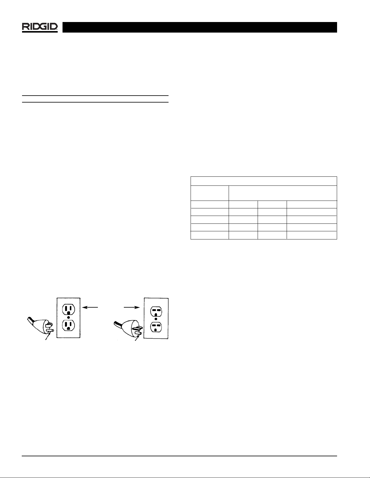
Grounding prong
Cover of
grounded
outlet box
Grounding prong
Minimum Wire Gauge for Extension Cord
Nameplate
Amps Total Length (in feet)
0-25 26-50 51-100
0-6 18 AWG 16 AWG 16 AWG
6-10 18 AWG 16 AWG 14 AWG
10-12 16 AWG 16 AWG 14 AWG
12-16 14 AWG 12 AWG
NOT RECOMMENDED

918 Roll Groover
Ridge Tool Company 3
Tool Use and Care
• Do not use tool if switch does not turn it ON or
OFF. Any tool that cannot be controlled with the switch
is dangerous and must be repaired.
• Disconnect plug from the power source before
making any adjustments, changing accessories, or
storing the tool. Such preventive safety measures re-
duce risk of starting the tool accidentally.
• Store idle tools out of the reach of children and
other untrained persons. Tools are dangerous in
the hands of untrained users.
• Check for misalignment or binding of moving parts,
breakage of parts, and any other condition that
may affect the tool’s operation. If damaged, have
the tool serviced before using. Many accidents are
caused by poorly maintained tools.
• Use only accessories that are recommended by the
manufacturer for your model. Accessories that may
be suitable for one tool may become hazardous when
used on another tool.
• Keep handles dry and clean; free from oil and
grease. This allows for better control of the tool.
Service
• Tool service must be performed only by qualified
repair personnel. Service or maintenance performed
by unqualified repair personnel could result in injury.
• When servicing a tool, use only identical replace-
ment parts. Follow instructions in the Maintenance
Section of this manual. Use of unauthorized parts or
failure to follow maintenance instructions may create a
risk of electrical shock or injury.
Specific Safety Information
WARNING
Foot Switch Safety
Using a threading machine without a foot switch increases
the risk of serious injury. A foot switch provides better
control by letting you shut off the motor by removing your
foot. If clothing should become caught in the machine, it will
continue to wind up, pulling you into the machine. Because
the machine has high torque, the clothing itself can bind
around your arm or other body parts with enough force to
crush or break bones.
Roll Groover Safety
• Roll Groover is made to groove pipe and tubing.
Follow instructions in Operator’s Manual on machine uses. Other uses may increase the risk of injury.
• Keep hands away from grooving rolls. Do not wear
loose fitting gloves when operating unit. Fingers
could get caught between grooving and drive rolls.
• Keep guards in place. Do not operate the groover
with guard removed. Exposure to grooving rolls may
result in entanglement and serious injury.
• Set-up Groover on a flat, level surface. Be sure
the machine, stand, and groover are stable. Will prevent tipping of the unit.
• Do not wear loose clothing. Keep sleeves and
jackets buttoned. Do not reach across the machine or pipe. Clothing can be caught by the pipe
resulting in entanglement and serious injury.
• Do not use this Roll Groover with a Power Drive or
Threading Machine that does not have a foot
switch. Foot switch is a safety device to prevent seri-
ous injury.
• When grooving pipe, keep hands away from the
end of the pipe. Do not reach inside pipe end. Will
prevent being cut on sharp edges and burrs.
• Be sure groover is properly secured to the power
drive or threading machine. Carefully follow the setup procedures. Will prevent tipping of the pipe or
grooving unit.
• Properly support pipe with pipe stands. Use two
pipe stands to groove pipe over 36″ long. Prevents
tipping of the unit.
• Use only power drives and threading machines
that operate under 58 RPM. Higher speed machines
increase the risk of injury.
• Lock foot switch when not in use.
(See Figure 1.)
Avoids accidental starting.
Figure 1 – Locked Foot Switch
WARNING
Read this operator’s manual carefully before using
the Roll Groover. Failure to understand and follow
the contents of this manual may result in electrical
shock, fire and/or serious personal injury.

Used in Conjunction with the Following Power
Drives and Threading Machines
• 300 Power Drive (38 and 57 RPM)
• 535 Threading Machine (38 and 54 RPM)
• 1822 Threading Machine
• 1224 Threading Machine
• 535 Automatic Threading Machine
Standard Equipment
918 Roll Groover Only
• 918 Groover with 2″ – 6″ drive shaft and groove set
•8″ – 12″ Drive shaft and groove set
• Carrying case for drive shaft and groove set
•1/8″ T-Handle hex wrench (groove roll change out)
• Wrench (drive shaft changeout)
918 Roll Groover Models
Roll Groover Assembly
Instructions
WARNING
The 918 Roll Groover should only be used with the
following power drives and threading machines.
• 300 Power Drive (38 and 57 RPM)
• 535 Threading Machine (38 and 54 RPM)
• 1822 Threading Machine
• 1224 Threading Machine
• 535 Automatic Threading Machine
Use only power drives and threading machines
that operate at 58 RPM or less. Higher speed machines increase risk of injury.
To prevent serious injury, proper assembly of the
Roll Groover is required. The following procedures
should be followed:
918 Roll Groover
Ridge Tool Company4
Description, Specifications and
Standard Equipment
Description
The RIDGID 918 Heavy Duty Roll Groover forms rolled
grooves in steel, stainless steel, aluminum, PVC pipe and
copper tubing. The grooves are formed by the hydraulic
feeding of a grooving roll into the pipe which is supported by a drive roll.
The 918 Roll Groover includes two (2) groove and drive
shaft sets that can groove the following pipe:
•2″ – 6″ Schedule 10 and 40
•8″ – 12″ Schedule 10 and 8″ Schedule 40
With additional roll sets, the groover can also be adapted
to groove the following:
•2″ – 6″ copper tubing (Types K, L, M, DWV);
•1″ Schedule 10 and 40;
•11/4″ – 11/2″ Schedule 10 and 40.
The 918 Heavy Duty Roll Groover is specifically designed
for use with the RIDGID 300 Power Drive, as well as
RIDGID 535, 535A, 1822, and 1224 Threading Machines.
Different mounting kits are required for each power source.
When properly used, the Model 918 makes
grooves that are dimensionally within the specifications of
AWWA C606-87. Selection of appropriate materials and
joining methods is the responsibility of the system designer and/or installer. Before any installation is attempted,
careful evaluation of the specific service environment, including chemical environment and service temperature,
should be completed.
Specifications
Roll Grooving Capacity
(See Table II for wall thickness)
•1″ – 12″ Schedule 10
•1″ – 8″ Schedule 40
•2″ – 6″ Copper types K, L, M, DWV
•2″ – 8″ Schedule 40 PVC
Do not use to groove 8″ schedule 40 steel
pipe harder than 150 BHN. Doing so may result in improperly formed grooves that do not meet required
specifications.
Depth Adjustment ..........Indexed adjustment knob
Actuation ........................Hydraulic hand pump
CAUTION
Catalog Model Weight
No. No. Description lb. kg.
48297 918-1 918 Roll Groover w/300 Power Drive Mount Kit 81 36,7
48377 918-2 918 Roll Groover w/1822 Carriage Mount Kit 81 36,7
48382 918-4 918 Roll Groover w/1224 Carriage Mount Kit 81 36,7
48387 918-5 918 Roll Groover w/535 Carriage Mount Kit 81 36,7
47222 918 Only 918 Roll Groover Only 75 34,0
Mounting Kit Only
48292 911 300 Power Drive Mount Kit Only 9 4
48392 912 1822 Carriage Mount Kit Only 39 17,7
48397 914 1224 Carriage Mount Kit Only 36 16,4
48402 915 535 Carriage Mount Kit Only 22 10
CAUTION

918 Roll Groover
Ridge Tool Company 5
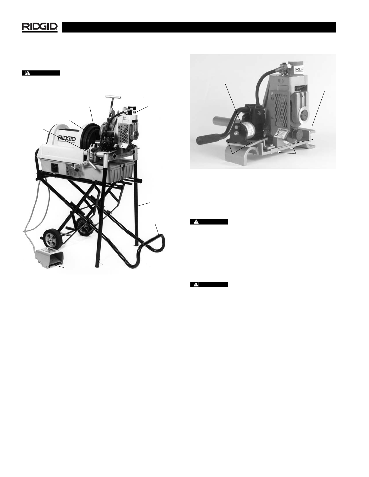
Installing the 918-1 Roll Groover on the
300 Power Drive
Figure 2 – Installing on 300 Power Drive
1. Remove carriage or other attachments from the 300
Power Drive.
2. Fully open front chuck of power drive.
3. Slide the base assembly onto the support arms of the
300 Power Drive.
(Figure 2)
4. Align the notched flats of the drive shaft with the
jaws on the 300 Power Drive chuck.
5. Close and tighten the front chuck.
Installing the 918-2 Roll Groover on the
1822 Threading Machine
Sub-Assembly
1. Position 918 Roll Groover on the mounting base as
shown in
Figure 3
.
2. Install and tighten the (2) 1/2″ x 11/4″ hex bolts which
connect 918 to mounting base.
3. Position hydraulic pump and securely bolt in place
with (4) 1/4″ x 3/4″ hex bolts.
4. Attach drive bar adapter to roll groover by tightening
two (2) set screws.
Figure 3 – 918 Heavy Duty Roll Groover on 1822 Mounting
Base
Installing on 1822 Threading Machine with 1406
Stand
1. Position carriage towards front chuck and swing tools
to the rear position. Remove carriage stop pin at the
end of rail.
Position reamer inside the die head to
prevent accidental contact.
2. Front chuck must be open. Position 918-2 so that the
base slides onto the support rails and drive bar feeds
into open chuck.
3. Place carriage stop pin in support rail hole.
4. Install support legs into socket holes on the base.
(Figure 4)
and tighten locking bolts.
Drive bar must be centered in front chuck
jaws. All bolts must be tight and the drive bar must be
securely held in chuck when closed.
Installing on 1822 Threading Machine with 100,
150, or 200 Stands
1. Position carriage towards front chuck and swing tools
to the rear position. Remove carriage stop pin at the
end of the rail.
Position reamer inside the die head to
prevent accidental contact.
2. Front chuck must be open. Position 918-2 so that the
base slides onto the support rails and drive bar feeds
into open chuck.
3. Replace carriage stop pin in support rail hole.
Drive Bar
Hydraulic
Pump
Mounting
Base
1
/
4
″ x
3
/
4
″
Bolts (4)
1
/
2
″ x 1
1
/
4
″
Bolts (2)
CAUTION
WARNING
CAUTION
918 Roll Groover
Ridge Tool Company6
NOTE! Support legs are not needed when when using
these stands.
Drive bar must be centered in front chuck
jaws. All bolts must be tight and the drive bar must be
securely held in chuck when closed.
Figure 4 – 918 Roll Groover Mounted on 1822 with 1406
Stand
Installing the 918-4 Roll Groover on the
1224 Threading Machine
Sub-Assembly
1. Align housing plate in recessed area of 1224.
2. Align 918 on the 1224 mounting base.
(Figure 5)
3. Install and tighten the (2) 1/2″ x 11/4″ hex bolts which
connect the 918 to mounting base.
4. Attach pump bracket with the two (2) 3/8″ x 1/2″ hex
bolts.
5. Position hydraulic pump and securely bolt in place
with (4) 1/4″ x 3/4″ hex bolts.
6. Attach drive bar adapter to roll groover by tightening
(2) set screws.
Figure 5 – 918 Heavy Duty Roll Groover on 1224
Threading Machine Mounting Base
Installing on 1224 Threading Machine
1. Position carriage towards front chuck and swing carriage tools to rear position.
Position reamer inside the die head to
prevent accidental contact.
2. Place 918-4 on the far side carriage rail and lower
onto near side rail.
(Figure 6)
3. Position base so that the drive bar feeds into the
open chuck.
4. Tighten chuck jaws securely into drive bar.
Drive bar must be centered in front chuck
jaws. All bolts must be tight and the drive bar must be securely held in chuck.
Front Chuck
Foot Switch
Drive Bar
Carriage
918-2
Sub-assembly
Hydraulic Pump
1224
Mounting
Base
1
/4″ x 3/4″ bolts (4)
for mounting
hydraulic pump
1
/2″ x 11/4″ bolts (2)
for mounting base
Support
Leg
Support
Leg
WARNING
1406
Stand
Housing
Plate
CAUTION
WARNING
 Loading...