

Page 1
• Français – 11
• Castellano – pág. 21
Power Drive
OPERATOR’S
MANUAL
600
WARNING!
Read this Operator’s Manual
carefully before using this
tool. Failure to understand
and follow the contents of this
manual may result in electrical shock, fire and/or serious
personal injury.
Page 2

600 Power Drive
Ridge Tool Companyii
Table of Contents
Recording Form for Machine Serial Number..............................................................................................................1
General Safety Information
Work Area Safety........................................................................................................................................................2
Electrical Safety..........................................................................................................................................................2
Personal Safety ..........................................................................................................................................................2
Tool Use and Care......................................................................................................................................................2
Service........................................................................................................................................................................3
Specific Safety Information
Power Drive Safety ....................................................................................................................................................3
Description, Specifications and Standard Equipment
Description..................................................................................................................................................................3
Specifications/Standard Equipment............................................................................................................................3
Accessories ................................................................................................................................................................4
Power Drive Inspection ................................................................................................................................................4
Tool and Work Area Set-Up..........................................................................................................................................5
Operating Instructions..................................................................................................................................................5
Accessories
Accessories For Power Drive......................................................................................................................................7
Maintenance Instructions
Motor Brush Replacement..........................................................................................................................................7
Tool Storage ..................................................................................................................................................................7
Service and Repair........................................................................................................................................................7
Wiring Diagram..............................................................................................................................................................8
Troubleshooting............................................................................................................................................................9
Lifetime Warranty .........................................................................................................................................Back Cover
Page 3
600
Portable Power Drive
600 Power Drive
Record Serial Number below and retain product serial number which is located on nameplate.
Serial
No.
Page 4

600 Power Drive
Ridge Tool Company2
General Safety Information
WARNING! Read and understand all instructions. Failure
to follow all instructions listed below may
result in electric shock, fire, and/or serious
personal injury.
SAVE THESE INSTRUCTIONS!
Work Area Safety
• Keep your work area clean and well lit. Cluttered
benches and dark areas invite accidents.
• Do not operate tools in explosive atmospheres,
such as in the presence of flammable liquids,
gases or dust. Tools create sparks which may ignite
the dust or fumes.
• Keep bystanders, children, and visitors away while
operating a tool. Distractions can cause you to lose
control.
• Keep floors dry and free of slippery materials
such as oil. Slippery floors invite accidents.
Electrical Safety
• Double Insulated tools are equipped with a polarized plug (one blade is wider than the other). This
plug will fit in a polarized outlet only one way. If the
plug does not fit fully in the outlet, reverse the
plug. If it still does not fit, contact a qualified electrician to install a polarized outlet. Do not change
the plug in any way. Double Insulation elim-
inates the need for the three wire grounded power cord
and grounded supply system.
• Avoid body contact with grounded surfaces. There
is an increased risk of electrical shock if your body is
grounded.
• Do not expose electrical tools to rain or wet con-
ditions. Water entering a tool will increase the risk of
electrical shock.
• Do not abuse cord. Never use the cord to pull the
plug from an outlet. Keep cord away from heat, oil,
sharp edges or moving parts. Replace damaged
cords immediately. Damaged cords increase the
risk of electrical shock.
• When operating a tool outside, use an outdoor
extension cord marked “W-A” or “W”. These cords
are rated for outdoor use and reduce the risk of electrical shock.
• Use proper extension cords. (See Chart) Insufficient
conductor size will cause excessive voltage drop and
loss of power.
• Keep all electric connections dry and off the
ground. Do not touch plugs or tool with wet hands.
Reduces the risk of electrical shock.
Personal Safety
• Stay alert, watch what you are doing and use
common sense when operating a power tool. Do
not use tool while tired or under the influence of
drugs, alcohol, or medications. A moment of inat-
tention while operating power tools may result in
serious personal injury.
• Dress properly. Do not wear loose clothing or
jewelry. Contain long hair. Keep your hair, clothing,
and gloves away from moving parts. Loose clothes,
jewelry, or long hair can be caught in moving parts.
• Avoid accidental starting. Be sure switch is OFF
before plugging in. Plugging in tools that have the
switch ON invites accidents.
• Remove adjusting keys or wrenches before turning
the tool ON. A wrench or a key that is left attached to
a rotating part of the tool may result in personal injury.
• Do not overreach. Keep proper footing and bal-
ance at all times. Proper footing and balance enables
better control of the tool in unexpected situations.
• Use safety equipment. Always wear eye protec-
tion. Dust mask, non-skid safety shoes, hard hat, or
hearing protection must be used for appropriate conditions.
Tool Use and Care
• Use clamp or other practical way to secure and
support the workpiece to a stable platform. Holding
the work by hand or against your body is unstable and
may lead to loss of control.
• Do not force tool. Use the correct tool for your
application. The correct tool will do the job better and
safer at the rate for which it is designed.
• Do not use tool if switch does not turn it ON or
OFF. Any tool that cannot be controlled with the
switch is dangerous and must be repaired.
Minimum Wire Gauge for Cord Set
Nameplate
Amps
Total Length (in feet)
0 – 25 26 – 50 51 – 100
0 – 6 18 AWG 16 AWG 16 AWG
6 – 10 18 AWG 16 AWG 14 AWG
10 – 12 16 AWG 16 AWG 14 AWG
12 – 16 14 AWG 12 AWG
NOT RECOMMENDED
Page 5

600 Power Drive
Ridge Tool Company 3
• Disconnect the plug from the power source before
making any adjustments, changing accessories, or
storing the tool. Such preventive safety measures
reduce the risk of starting the tool accidentally.
• Store idle tools out of the reach of children and
other untrained persons. Tools are dangerous in
the hands of untrained users.
• Maintain tools with care. Keep cutting tools sharp
and clean. Properly maintained tools with sharp
cutting edges are less likely to bind and are easier to
control.
• Check for misalignment or binding of moving
parts, breakage of parts, and any other condition
that may affect the tool’s operation. If damaged,
have the tool serviced before using. Many acci-
dents are caused by poorly maintained tools.
• Use only accessories that are recommended for
your model. Accessories that may be suitable for
one tool may become hazardous when used on
another tool.
• Keep handles dry and clean; free from oil and
grease. Allows for better control of the tool.
Service
• Tool service must be performed only by qualified
repair personnel. Service or maintenance per-
formed by unqualified repair personnel could result in
injury.
• When servicing a tool, use only identical replacement parts. Follow instructions in the Maintenance
Section of this manual. Use of unauthorized parts or
failure to follow maintenance instructions may create a
risk of electrical shock or injury.
Specific Safety Information
WARNING
Read this operator’s manual carefully before using
the 600 Power Drive. Failure to understand and follow the contents of this manual may result in
electrical shock, fire and/or serious personal injury.
Call the Ridge Tool Company, Technical Service Department at (800) 519-3456 if you have any questions.
Power Drive Safety
• The Power Drive is made to turn threaders and
other equipment. Follow instructions in this
Operator’s Manual on proper use when threading. When using it to power other equipment, read
and follow the safety and operating instructions
provided with that equipment. Other uses may
increase the risk of serious injury.
• Secure Power Drive using the No. 601 Support
Arm. Hold Power Drive firmly. If the Power Drive
cannot be secured by a Support Arm, use other
mechanical means. Resists high handle forces devel-
oped during use and prevents losing control of the tool.
– Only use the aluminum gear case to secure the
power drive. Using the motor housing or handle
may result in damaging or breaking these parts.
• Do not use dull or damaged dies. Sharp cutting
tools require less torque and the Power Drive is easier to control.
• Do not use if ON/OFF switch is broken. The pur-
pose of the switch is to provide better control by letting
you shut off the motor be removing your finger.
• Do not wear gloves or loose clothing when operating Power Drive. Keep sleeves and jackets buttoned. Clothing can be caught resulting in entangle-
ment and serious injury.
Description, Specifications and
Standard Equipment
Description
The RIDGID Model 600 Power Drive is a double insulated drive which provides power for threading pipe and
conduit. Forward and Reverse rotation can be selected
with a REV/FOR switch while ON/OFF is controlled by a
paddle switch that cuts off power when released.
The Power Drive is designed for use with the No. 11R
Die Heads (1/8″ – 11/4″ pipe). A manual oiling system is
available to flood the work during the threading operations. The No. 601 Support Arm should be used to
secure the Power Drive and resist the torque developed during threading.
Specifications/Standard Equipment
Pipe and Conduit...........11-R Drop Head Die Heads:
1
/8″ - 11/4″ (3mm – 32mm)
Motor:
Type............................Universal
Page 6
Volts............................115V Single Phase AC (220V
available) 50-60 HZ
Amps.............................15 amps
Watts.............................1020
Switches:
ON/OFF ......................Heavy Duty Paddle Type with
Safety Locking Device
Direction Change........FOR/REV Switch
Gear Head.....................Die Cast Aluminum Housing,
Permanently Greased.
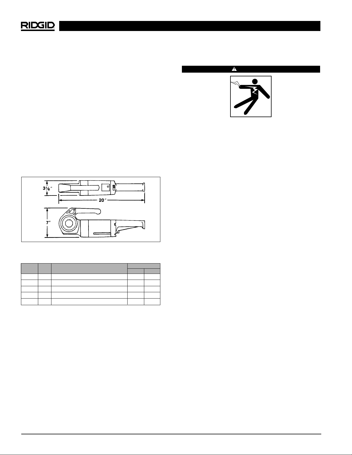
Length ...........................20″ (51cm)
Weight...........................12.5 lbs. (5.5 kg)
No. 601 Support Arm.....Absorbs Power Drive Torque
Accessories
No. 11-R Die Heads (7)...1/8″, 1/4″, 3/8″, 1/2″, 3/4″, 1″, 11/4″
No. 418 Oiler.................Oiler with 1 gallon RIDGID
Thread Cutting Oil
Carrying Case ...............For Power Drive and 6 Die
Heads
Power Drive Inspection
WARNING
To prevent serious injury, inspect your Power
Drive. The following inspection procedures should
be performed on a daily basis:
1. Make sure Power Drive is unplugged.
2. Inspect the power cord and plug for damage. If the
plug has been modified or if the cord is damaged, do
not use the Power Drive until the cord has been
replaced.
3. Inspect the Power Drive for any broken, missing,
misaligned or binding parts as well as any other conditions which may affect the safe and normal operation of the tool. If any of these conditions are present,
do not use the Power Drive until any problem has
been repaired.
4. Use tools and accessories that are designed for your
Power Drive and meet the needs of your application.
The correct tools and accessories allow you to do the
job successfully and safely. Accessories suitable for
use with other equipment may be hazardous when
used with this Power Drive.
5. Clean any oil, grease or dirt from all equipment handles and controls. This reduces the risk of injury due
to a tool or control slipping from your grip.
Inspect the cutting edges of your dies. If necessary,
have them replaced prior to using the Power Drive.
Dull or damaged dies can lead to binding and poor
quality threads.
6. Clean metal shavings and other debris from the chip
tray of the 418 Oiler. Check the level and quality of the
thread cutting oil. Replace or add oil if necessary.
NOTE! Thread cutting oil lubricates and cools the
threads during the threading operation. A dirty or
poor grade cutting oil can result in poor thread
quality.
600 Power Drive
Ridge Tool Company4
Figure 1 – 600 Power Drive Dimensions
Catalog
No.
36902
36912
36917
36932
36937
Description
115V Kit Less Die Head w/Case
115V
1
/2″ – 11/4″ NPT w/Case
115V 1/2″ – 11/4″ BSPT w/Case, Export
220V 1/2″ – 11/4″ NPT w/Case, Export
220V
1
/2″ – 11/4″ BSPT w/Case, Export
lb.
26
36
36
36
36
Weight
Model
No.
600
600
600
600
600
kg
11,8
16,4
16,4
16,4
16,4
Page 7
Tool and Work Area Set-Up
WARNING
To prevent serious injury, proper set-up of the
Power Drive and work area is required. The following procedures should be followed to set-up the
tool.
1. Locate a work area that has the following:
• Adequate lighting.
• No flammable liquids, vapors or dust that may ignite.
• Clear path to the electrical outlet that does not
contain any sources of heat or oil, sharp edges or
moving parts that may damage electrical cord.
• Dry place for operator. Do not use the Power Drive
while standing in water.
• Level ground for tristand vise and pipe stands.
2. Clean up the work area prior to setting up any equipment. Always wipe up any oil that may have splashed
or dripped from the oiler to prevent slips and falls.
3. Plug the Power Drive into the electrical outlet making
sure to position the power cord along the clear path
selected earlier. If the power cord does not reach the
outlet, use an extension cord in good condition.
To avoid electrical shock and electrical
fires, never use an extension cord that is damaged or
does not meet the following requirements:
• The cord is rated as “W” or “W-A” if being used out-
doors.
• The cord has sufficient wire thickness (14 AWG
below 25′/12 AWG 25′ - 50′). If the wire thickness is
too small, the cord may overheat, melting the cord’s
insulation or causing nearby objects to ignite.
To reduce risk of electrical shock, keep
all electrical connections dry and off the ground. Do
not touch plug with wet hands.
4. Check the Power Drive to insure it is operating
properly.
• Depress the switch and make sure it controls the
stopping of the Power drive by releasing the switch.
• Depress and hold the switch. Inspect the moving
parts for misalignment, binding, odd noises or any
other unusual conditions that may affect the safe
and normal operation of the tool. If such conditions are present, have the power drive serviced.
• Flip the directional switch to the opposite direction. Check that that power drive rotates in an
opposite direction.
Change position of the directional switch
only when motor is switched OFF.
Operating Instructions For
Threading With Drop Head
Die Heads
WARNING
Do not wear gloves or loose clothing when operating
Power Drive. Keep sleeves and jackets buttoned.
Do not use this Power Drive if switches are broken. Always wear eye protection to protect eyes
from dirt and other foreign objects.
When threading pipe
3
/4″ or larger, use the No. 601
Support Arm to resist high handle force developed during threading.
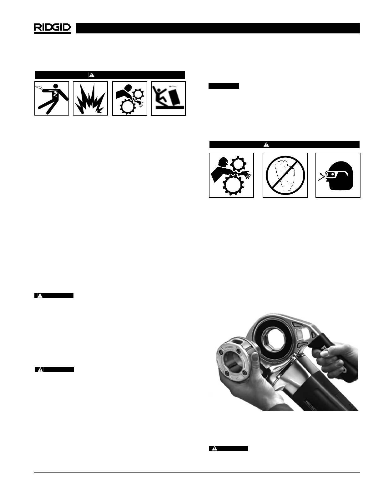
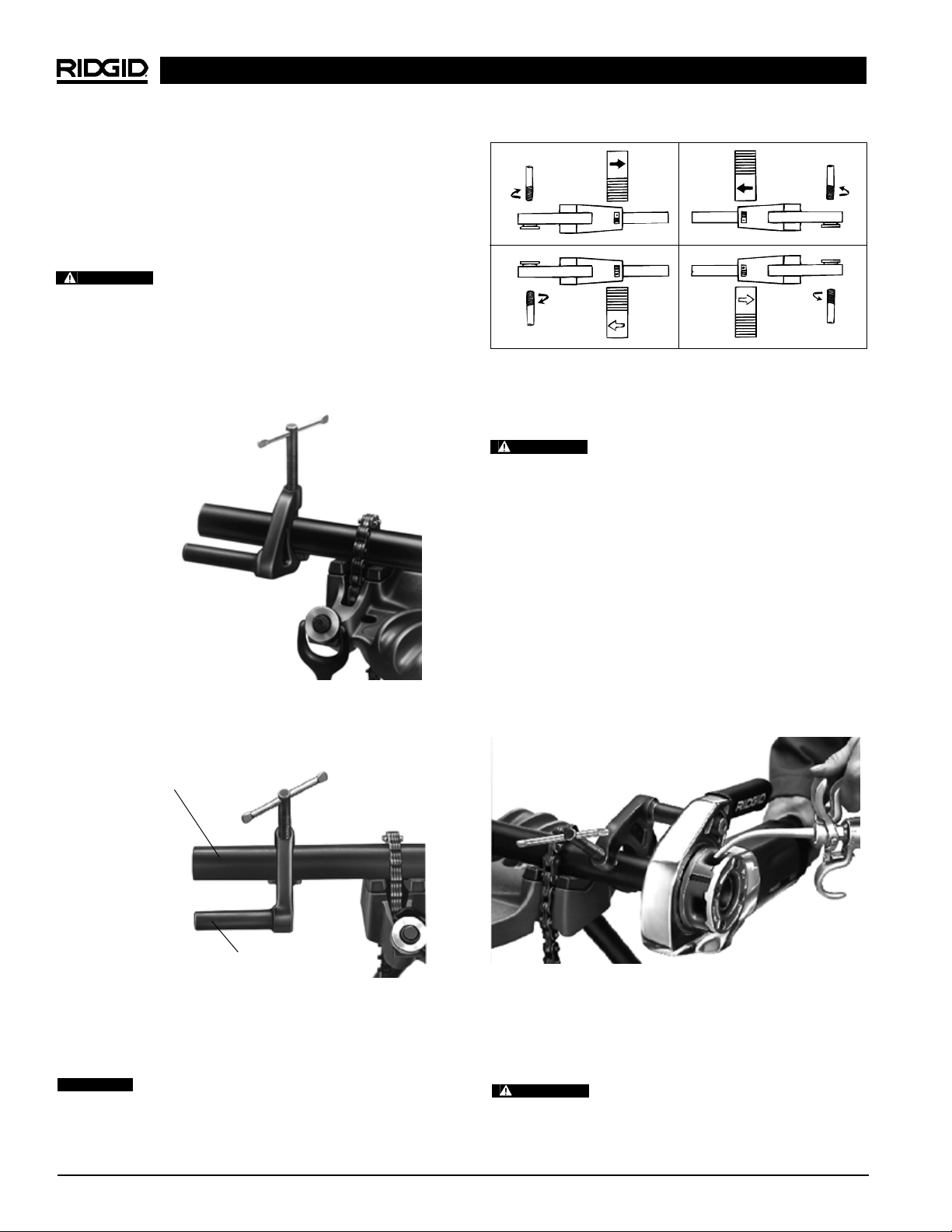
1. Push Die Heads, spline end first, squarely into the
Power Drive until the spring catches securely
(Figure 2).
NOTE! Installation can be made into either side of the
Power Drive.
Figure 2 – Installing No. 11-R Drop Head Die Head
2. If possible, secure the pipe in a portable tristand vise
or a bench vise.
To prevent tipping, long lengths of pipe
should also be supported with pipe stand.
600 Power Drive
Ridge Tool Company 5
CAUTION
WARNING
WARNING
WARNING
Page 8
3. Be sure the 418 Oiler is properly filled with RIDGID
Thread Cutting Oil. Position the oiler in front of the
vise.
4. Position No. 601 Support Arm on pipe so end of
torque arm is in line with end of the pipe (Figures 3
& 4).
To avoid serious injury from losing control
of the Power Drive, a support arm should be used when
threading 3/4″ or larger pipe.
When threading pipe less than 3/4″ in size without a
support arm, hold onto the Power Drive firmly with
one hand to exert pressure against the handle forces
developed during threading.
5. Position the directional switch for the desired right or
left hand thread (Figure 5).
Change position of the directional switch
only when the motor is switched OFF.
6. Place Die Head over end of pipe.
To avoid serious injury, make sure Power
Drive is correctly positioned on support arm. For right
hand threads, die head will rotate clockwise (looking
at the face of the Die Head). Forces developed by the
threading torque will be in the opposite or counter-clockwise direction.
7. Simultaneously actuate the ON/OFF switch and exert
pressure against the Die Head with the palm of free
hand to make sure thread is started. Apply plenty of
thread cutting oil to the dies during threading. This will
reduce the torque required to thread and improve
the thread quality (Figure 6).
8. Keep ON/OFF switch depressed until end of the pipe
is even with edge of the dies and release the switch
button.
9. Back off the Die Head from the threaded pipe, revers-
ing the directional switch and actuating the ON/OFF
switch.
Hold onto the Power Drive handle firmly
to resist handle forces developed while backing off the
Die Head.
600 Power Drive
Ridge Tool Company6
Figure 6 – Threading Pipe and Applying Oil
Figure 3 – Using No. 601 Support Arm when threading
3
/4″ pipe and larger
Figure 4 – Positioning No. 601 Torque Arm in Line with
End of Pipe
Pipe
Torque Arm
A. Right Hand Thread B. Left Hand Thread
Figure 5 – Direction Change Switch/Die Head
Orientation.
WARNING
CAUTION
WARNING
WARNING
Page 9

Service and Repair
WARNING
Service and repair work on this Power Drive must be performed by qualified repair personnel. Tool should be
taken to a RIDGID Independent Authorized Service
Center or returned to the factory. All repairs made by
Ridge service facilities are warranted against defects in
material and workmanship.
When servicing this Power Drive, only identical replacement parts should be used. Failure to follow these
instructions may create a risk of electrical shock or
other serious injury.
If you have any questions regarding the service or repair
of this machine, call or write to:
Ridge Tool Company
Technical Service Department
400 Clark Street
Elyria, Ohio 44035-6001
Tel: (800) 519-3456
E-Mail: techservices@ridgid.com
For name and address of your nearest Independent
Authorized Service Center, contact the Ridge Tool
Company at (800) 519-3456 or http://www.ridgid.com
600 Power Drive
Ridge Tool Company 7
10. When dies clear the end of the pipe, grip the handle
on top of the Power Drive and remove the Power
Drive and Die Head from the pipe.
11. Remove the support arm from the pipe and the pipe
from the vise.
To avoid injury, make sure long sections
of pipe are supported at the end farthest away from
the vise prior to removal.
12. Clean up any oil spills or splatter on the ground sur-
rounding the vise and oiler.
Accessories
WARNING
Only the following RIDGID products have been designed
to function with the 600 Power Drive. Other accessories
designed for use with other tools may become hazardous when used on this Power Drive. To prevent
serious injury, use only the accessories listed below.
Accessories For Power Drive
NOTE! See Ridge Tool catalog for listing of 11-R Die
Heads, Pipe Supports, Vises and Thread Cutting
Oil. No. 11-R Die Heads use 12-R replacement
Dies.
Maintenance Instructions
WARNING
Make sure machine is unplugged from power
source before performing maintenance or making any adjustment.
Motor Brush Replacement
Check motor brushes every 6 months and replace
brushes when they are worn to less than 1/4″.
Tool Storage
WARNING
Motor-driven equipment must be kept indoors or well
covered in rainy weather. Store the Power Drive in a
locked area that is out of reach of children and people
unfamiliar with power drives. This power tool can cause
serious injury in the hands of untrained users.
WARNING
Model No. Description
418 Oiler with 1 Gallon of NU-Clear Thread Cutting Oil
601 Support Arm
— Carrying Case
— Gearhead Motor Grease
Page 10
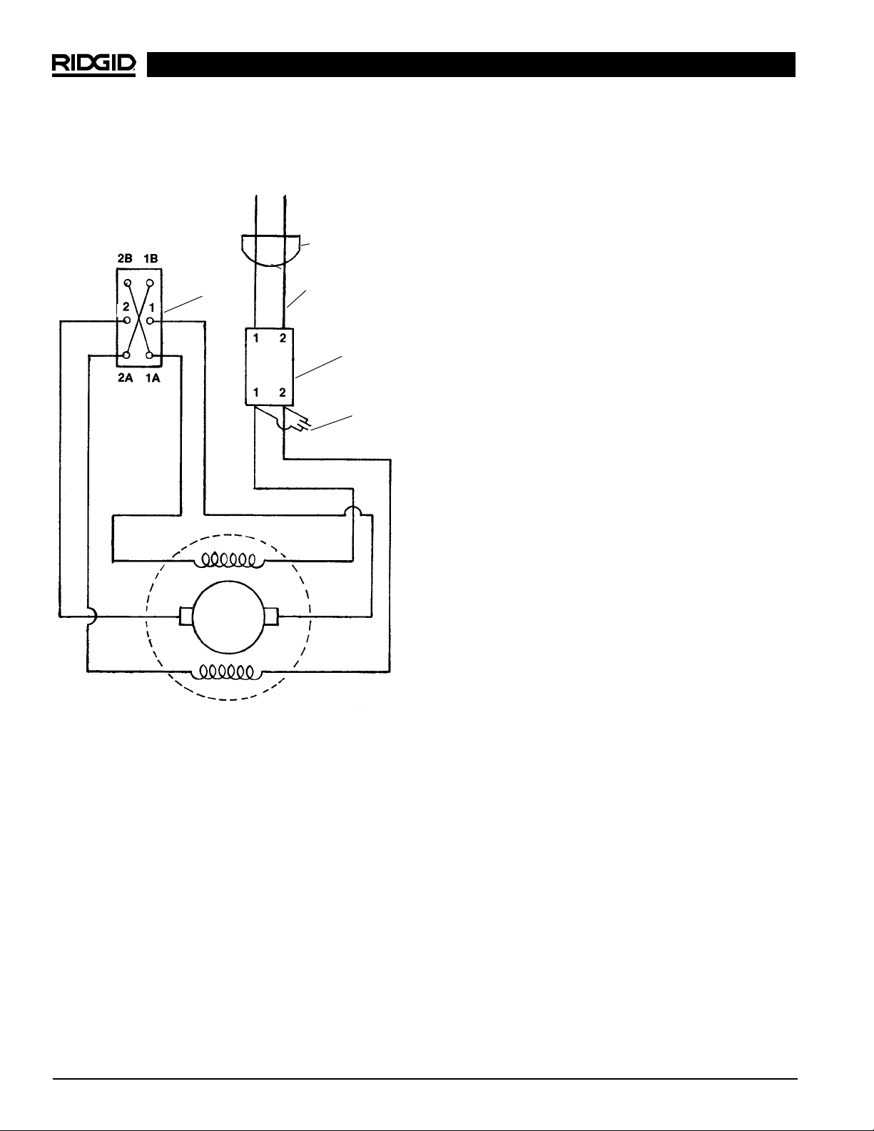
Wiring Diagram — 600
600 Power Drive
Ridge Tool Company8
FOR/REV
Switch
115 VAC
(220 VAC)
ON/OFF Switch
Plug
Suppressor
(220V Only)
Black
(Blue)
White
(Brown)
Blue
Grey
Blue
Grey
White
White
Page 11

600 Power Drive
Ridge Tool Company 9
Troubleshooting
WARNING: Always unplug power cord before servicing Power Drive.
Troubleshooting Table
Power drive unplugged
Fuse blown
Brushes do not touch armature
Overload because of dull dies
Bad quality or insufficient thread cutting oil
Bad contact between brushes and brush holder
Brushes do not touch commutator properly
Brushes of different manufacture
Sharp edge on brush
Dull or broken dies
Machine running in wrong direction
Improperly set dies
Dull dies
Dies not assembled in correct sequence
Low quality pipe
Bad quality or insufficient thread cutting oil
Support arm jaws dirty
Burr has occurred at the spline end of the die head
Plug into power source
Install new fuse
Check brushes, replace if worn
Replace dies
Use RIDGID thread cutting oil in adequate
quantity
Tighten the screws, make sure brush is pressed
firmly onto commutator
Replace worn brushes
Only use original brushes
Break edge
Replace dies
Check setting of the direction switch
Reset dies
Replace dies
Put dies in correct sequence
Make sure only pipe of good quality is used
Use only RIDGID thread cutting oil in adequate
quantity
Clean with wire brush
Eliminate burr with file
PROBLEM CAUSE CORRECTION
Motor does not start
Motor cannot be loaded
Sparks forming at motor
Die head does not start
threading
Damaged Thread
Support arm turns while
threading
Die heads cannot be
changed properly
Page 12

600 Power Drive
Ridge Tool Company10
Page 13

Système d’entraînement
portatif n° 600
Système d’entraînement n° 600
Inscrivez ci-dessous le numéro de série de la plaque signalétique l’appareil pour future référence.
N° de
série :
Page 14

Système d’entraînement n° 600
Ridge Tool Company12
Table des Matières
Fiche d’enregistrement du numéro de série de l’appareil ......................................................................................11
Consignes générales de sécurité
Sécurité du chantier..................................................................................................................................................13
Sécurité électrique....................................................................................................................................................13
Sécurité personnelle ................................................................................................................................................13
Utilisation et entretien des outils ..............................................................................................................................14
Service après-vente..................................................................................................................................................14
Consignes de sécurité particulières
Sécurité du système d’entraînement ........................................................................................................................14
Description, spécifications et équipements de base
Description................................................................................................................................................................15
Spécifications............................................................................................................................................................15
Equipements ............................................................................................................................................................15
Accessoires ..............................................................................................................................................................15
Inspection du système d’entraînement ....................................................................................................................16
Préparation de l’appareil et du chantier....................................................................................................................16
Utilisation de l’appareil ..............................................................................................................................................17
Accessoires
Accessoires pour système d’entraînement ..............................................................................................................19
Entretien
Remplacement des balais du moteur ......................................................................................................................19
Stockage de l’appareil ................................................................................................................................................19
Service après-vente, réparations ..............................................................................................................................19
Schéma électrique ......................................................................................................................................................19
Dépannage ..................................................................................................................................................................20
Garantie à vie ..........................................................................................................................................Page de garde
Page 15

Système d’entraînement n° 600
Ridge Tool Company 13
Consignes générales de sécurité
MISE EN GARDE ! Familiarisez-vous avec l’ensemble des
instructions. Le non respect des consignes ci-devant augmenterait les
risques de choc électrique, d’incendie
et d’accident grave.
CONSERVEZ CES INSTRUCTIONS !
Sécurité du chantier
• Gardez le chantier propre et bien éclairé. Les établis encombrés et les locaux mal éclairés sont des invitations aux accidents.
• N’utilisez pas d’appareils électriques dans un
milieu explosif tel qu’en présence de liquides, de
gaz ou de poussières inflammables. L’appareil pro-
duit des étincelles qui pourraient provoquer la combustion des poussières et vapeurs.
• Gardez les tiers, les enfants et les visiteurs à
l’écart lorsque vous utilisez un appareil électrique.
Les distractions peuvent vous faire perdre le contrôle
de l’appareil.
• Assurez-vous que les sols sont secs et exempts
d’huile ou d’autres matières visqueuses. Les sols
glissants sont une invitation aux accidents.
Sécurité électrique
• Les appareils électriques à double isolation sont
équipés d’une fiche polarisée dont une des barrettes est plus large que l’autre. Cette fiche ne
peut être introduite dans une prise polarisée que
dans un seul sens. Si la fiche refuse de s’introduire complètement dans la prise, tournez-la à
l’envers. Si elle refuse toujours de s’introduire,
demandez à un électricien qualifié d’installer une
prise polarisée. Ne pas tenter de modifier la prise
d’une manière quelconque. La double isolation
élimine le besoin d’un cordon d’alimentation à deux
fils plus terre et la nécessité d’un circuit d’alimentation
avec terre.
• Evitez tout contact avec les surfaces reliées à la
terre. Le contact avec des masses augmente les
risques de choc électrique.
• N’exposez pas les appareils électriques aux
intempéries ou à l’eau. Toute pénétration d’eau à
l’intérieur de l’appareil augmente les risques de choc
électrique.
• Ne maltraitez pas le cordon électrique de l’appareil.
Ne jamais porter l’appareil par son cordon électrique, ni tirer sur celui-ci pour débrancher
l’appareil. Gardez le cordon à l’abri des sources de
chaleur, de l’huile, des angles tranchants et des
pièces mobiles. Remplacez immédiatement tout
cordon endommagé. Les cordons endommagés
augmentent les risques de choc électrique.
• WA l’extérieur, utilisez une rallonge électrique
portant l’indication “W-A” ou “W”. Ce type de cordon est prévu pour être utilisé à l’extérieur et réduit les
risques de choc électrique.
• Utilisez la section de rallonge appropriée (voir le
tableau). Une section de conducteurs insuffisante
entraînera des pertes de charge excessive et un
manque de puissance.
• Gardez les rallonges électriques au sec et
surélevées. Ne touchez pas les fiches électriques
ou l’appareil avec les mains mouillées. Cette pré-
caution a pour but de limiter les risques de choc
électrique.
Sécurité personnelle
• Restez attentif, faites attention à ce que vous faites
et faites preuve de bon sens lorsque vous utilisez
un appareil électrique. N’utilisez pas ce type
d’appareil lorsque vous êtes fatigués ou sous
l’influence de drogues, de l’alcool ou de médicaments. Lors de l’utilisation des appareils électriques, un
instant d’inattention peut provoquer un accident grave.
• Habillez-vous de manière appropriée. Ne portez
pas de vêtements amples ni de bijoux. Attachez les
cheveux longs. Gardez vos cheveux, vos vêtements et vos gants à l’écart des pièces mobiles.
Les vêtements amples, les bijoux et les cheveux longs
peuvent être entraînés dans le mécanisme.
• Evitez les risques de démarrage accidentel.
Assurez-vous que l’interrupteur marche/arrêt est en
position OFF (arrêt) avant de brancher l’appareil.
Brancher un appareil lorsque son interrupteur est en
position de marche est une invitation aux accidents.
• Enlevez les clés de réglage et autres outils avant
de mettre l’appareil en marche. Une clé laissée sur
une partie rotative de l’appareil peut s’avérer très dan-
gereuse.
Section minimale des fils conducteurs des rallonges
Ampères indiqués
sur la plaque Longueur totale (en pieds)
signalétique
0 à 25 26 à 50 51 à 100
0 à 6 18 AWG 16 AWG 16 AWG
6 à 10 18 AWG 16 AWG 14 AWG
10 à 12 16 AWG 16 AWG 14 AWG
12 à 16 14 AWG 12 AWG
Déconseillé
Page 16

Système d’entraînement n° 600
Ridge Tool Company14
• Ne vous mettez pas en porte-à-faux. Maintenez
une bonne assise et un bon équilibre à tout
moment. Une bonne assise et un bon équilibre vous
permettent de mieux contrôler l’appareil en cas
d’imprévu.
• Utilisez les équipements de sécurité appropriés.
Portez systématiquement des lunettes de sécurité.
Un masque à poussière, des chaussures de sécurité, le casque et/ou une protection auditive doivent être
portés selon les conditions d’utilisation.
Utilisation et entretien de l’appareil
• Utiliser une pince ou autre dispositif approprié
pour fixer et soutenir l’ouvrage sur une plateforme stable. Tenir un ouvrage à la main ou contre le
corps n’assure pas une stabilité suffisante et risque de
vous en faire perdre le contrôle.
• Ne forcez pas l’outil. Utilisez l’outil prévu por
l’application en question. L’outil approprié fera
mieux son travail et assurera une meilleure sécurité lorsqu’il est utilisé au régime prévu.
• N’utilisez pas un appareil si son interrupteur ne
permet pas de le mettre en marche ou de l’arrêter.
Tout appareil qui ne peut pas être contrôlé par son
interrupteur est dangereux et doit être réparé.
• Débranchez le cordon électrique de l’appareil
avant tout réglage, changement d’accessoires ou
rangement de celui-ci. De telles mesures préventives
réduisent le risque de démarrage accidentel de
l’appareil.
• Rangez les appareils non utilisés hors de la portée
des enfants et des personnes non-initiées. Ces
appareils sont dangereux entre les mains de personnes non initiées.
• Entretenez les outils soigneusement. Gardez les
outils de coupe bien affûtés et en bon état de propreté. Les outils bien entretenus avec des tranchants
bien affûtés minimisent les risques de grippage et
sont plus faciles à contrôler.
• Assurez-vous qu’il n’y a pas de mauvais alignement ou de grippage des pièces rotatives ou
d’autres conditions qui pourraient entraver le bon
fonctionnement de l’appareil. Le cas échéant, il
sera nécessaire de faire réparer l’appareil avant de
vous en servir. De nombreux accidents sont le résul-
tat d’un appareil mal entretenu.
• Utilisez exclusivement les accessoires recom-
mandés par le fabricant pour votre appareil particulier. Des accessoires prévus pour un certain type
d’appareil peuvent être dangereux lorsqu’on tente de
les adapter à un autre.
• Gardez les poignées de l’appareil propres, sèches
et dépourvues d’huile ou de graisse. Cela vous
permettra de mieux contrôler l’appareil.
Service après-vente
• Toutes réparations de l’appareil doivent être confiées à un réparateur qualifié. La réparation ou
l’entretien de l’appareil par du personnel non qualifié
peut entraîner des accidents.
• Lors de la réparation de l’appareil, utilisez exclusivement des pièces de rechange identiques à
celles d’origine. Suivez les instructions de la section “Entretien” du mode d’emploi. L’utilisation de
pièces de rechange non homologuées ou le non
respect des consignes d’entretien augmenterait les
risques de choc électrique et d’accident.
Consignes de sécurité
particulières
MISE EN GARDE !
Familiarisez-vous avec ce mode d’emploi avant
de tenter d’utiliser le système d’entraînement n°
600. Le non respect des consignes qu’il contient
augmenterait les risques de choc électrique,
d’incendie et d’accident grave.
En cas de questions, veuillez consulter les services
techniques de la Ridge Tool Company en composant le
(800) 519-3456.
Sécurité du système d’entraînement
• Ce système d’entraînement sert à mouvoir les
machines à fileter et autres types de matériel.
Lors du filetage, suivez les instructions ciprésentes sur son utilisation appropriée. Lors de
son utilisation avec d’autres types de matériel,
appliquez les consignes de sécurité et d’utilisation
du matériel en question. Toute application non
prévue peut augmenter les risques d’accident.
• Arrimez le système d’entraînement à l’aide du sup-
port de tube n° 601. Tenez le système d’entraînement fermement. Si le système d’entraînement ne
peut pas être arrimé à l’aide du support de tube,
prévoyez un autre système d’arrimage. L’idée étant
d’absorber le couple transmis à la poignée durant
l’utilisation et éviter la perte de contrôle de l’appareil.
– N’arrimez l’appareil que par son carter d’en-
grenages en aluminium. L’arrimage du carter
Page 17

Interrupteurs :
marche/arrêt................interrupteur à bascule indus-
triel avec verrouillage
inverseur.....................interrupteur FOR/REV
(avant/arrière)
Tête d’engrenages ........Carter en fonte d’aluminium,
lubrification permanente
Longueur.......................51 cm (20 po)
Poids .............................5,5 kg (12,5 livres)
Support de tube
n° 601 .............................Absorbe le couple développé
par le système d’entraînement
Accessoires
Têtes de filière (7)
n° 11-R ............................1/8, 1/4, 3/8, 1/2, 3/4, 1 et 11/4po
Système de lubrification
n° 418............................Système de lubrification avec
1 gallon d’huile de coupe
RIDGID
Coffret............................portant système d’entraîne-
ment + 6 têtes de filière
Système d’entraînement n° 600
Ridge Tool Company 15
moteur ou de la poignée risque d’endommager ces
pièces.
• Ne pas utiliser de filières émoussées ou endommagées. Les outils de coupes bien affûtés nécessitent
moins de couple et facilitent le contrôle du système
d’entraînement.
• Ne pas utiliser si l’interrupteur marche/arrêt est
endommagé. Cet interrupteur vous assure un meilleur
contrôle de l’appareil en l’arrêtant dès que vous retirez
le doigt.
• Ne portez pas de gants ou de vêtements trop
amples lors de l’utilisation du système d’entraînement. Boutonnez vos manches et vos blousons.
Les vêtements risquent d’être entraînés dans le
mécanisme et provoquer de graves blessures.
Description, spécifications et
équipements de base
Description
Le système d’entraînement RIDGID n° 600 est un
appareil à double isolation qui assure l’entraînement
des machines à fileter les tuyaux et conduits. Son
inverseur (REV/FOR) permet de changer de sens de
rotation, tandis que son interrupteur marche/arrêt
(ON/OFF) à bascule assure son arrêt immédiat dès
qu’il est lâché.
Ce système d’entraînement est prévu pour les têtes de
filière n° 11R (pour tuyaux de 1/8à 11/4po de diamètre).
Un système de lubrification manuel est disponible pour
assurer l’inondation de l’ouvrage en cours de filetage. Le
support de tube n° 601 devrait être utilisé pour arrimer le
système d’entraînement et absorber le couple développé durant le filetage.
Spécifications et équipements de base
Tuyaux et conduits........Têtes de filières orientables
type 11-R de 3 à 32 mm (1/8à
11/4po)
Moteur :
Type............................Universel
Alimentation
électrique ....................115V monophasé, courant
alternatif (220V disponible),
50-60 Hz
Ampères........................15A
Watts.............................1020
Figure 1 – Dimensions du système d’entraînement n° 600
Réf.
Cat.
36902
36912
36917
36932
36937
Description
Kit 115V + coffret (sans tête de filière)
115V,
1
/2à 11/4po NPT + coffret
115V Export,
1
/2à 11/4po BSPT + coffret
220V Export, 1/2à 11/4po NPT + coffret
220V Export,
1
/2à 11/4po BSPT + coffret
(lb)
26
36
36
36
36
Poids
Modèle
600
600
600
600
600
(kg)
11,8
16,4
16,4
16,4
16,4
Page 18

Système d’entraînement n° 600
Ridge Tool Company16
Inspection du système
d’entraînement
MISE EN GARDE !
Inspectez le système d’entraînement afin d’éviter
les risques d’accident grave. L’inspection suivante doit être effectuée au quotidien :
1. Vérifiez que le système d’entraînement est
débranché.
2. Inspectez le cordon d’alimentation et sa fiche pour
signes de détérioration. Si la fiche a été modifiée
ou le cordon endommagé, ne pas utiliser le système
d’entraînement avant que le cordon ait été remplacé.
3. Inspectez le système d’entraînement pour signes
de pièces brisées, manquantes, mal alignées ou
grippées, ainsi que pour toutes autres conditions qui
pourraient nuire à la sécurité ou à l’utilisation normale
de l’appareil. Le cas échéant, ne pas utiliser le système d’entraînement avant de l’avoir réparé.
4. Utilisez les outils et accessoires prévus pour ce système d’entraînement particulier et qui répondent aux
besoins de l’application envisagée. Les outils et
accessoires appropriés assurent un meilleur travail et
une meilleure sécurité. L’adaptation à ce système
d’entraînement d’accessoires prévus pour d’autres
types d’appareils peut s’avérer dangereuse.
5. Eliminez toutes traces d’huile, de graisse et de crasse
des poignées et des commandes de l’appareil. Cela
réduira les risques de perte de contrôle de l’appareil
et les risques d’accident correspondants.
Examinez le tranchant des filières. Si nécessaire,
remplacez les filières avant d’utiliser ce système
d’entraînement. Des filières émoussées ou endommagées peuvent provoquer le grippage de l’appareil
ou produire une mauvaise qualité de filetage.
6. Nettoyez le tiroir à copeaux du système de lubrification n° 418 de tous copeaux métalliques et autres
débris. Vérifiez le niveau et l’état de l’huile de filetage.
Remplacez l’huile ou faites-en l’appoint selon besoin.
NOTA ! L’huile de coupe permet de lubrifier et refroidir
les filets durant l’opération de filetage. Une
huile de coupe encrassée ou de mauvaise
qualité risque de produire des filetages de
mauvaise qualité.
Préparation de l’appareil et
du chantier
MISE EN GARDE !
Afin d’éviter les risques d’accident grave, il est
nécessaire de préparer l’appareil et le chantier
de manière appropriée. Respectez les consignes
suivantes lors de la préparation de l’appareil.
1. Assurez-vous que le chantier a les caractéristiques
suivantes :
• Suffisamment d’éclairage.
• Absence de liquides, vapeurs ou poussières com-
bustibles.
• Un passage dégagé jusqu’à la prise de courant
sans sources de chaleur, sans huile, sans arrêtes
vives, et sans mécanismes qui risqueraient
d’endommager le cordon d’alimentation.
• Un endroit sec pour l’opérateur. Ne pas utiliser le
système d’entraînement lorsque vous avez les
pieds dans l’eau.
• Un sol de niveau pour l’étau à trépied et les porte-
tubes.
2. Nettoyez le chantier avant d’installer le matériel.
Essuyez systématiquement toutes traces d’huile qui
auraient put s’éclabousser ou s’écouler de l’appareil
ou du système de lubrification afin d’éviter les risques
de dérapage et de chute.
3. Branchez le cordon d’alimentation du système
d’entraînement en faisant attention de suivre le passage dégagé précédemment établi. Si le cordon d’ali-
mentation n’arrive pas jusqu’à la prise d’alimentation, utilisez une rallonge électrique en bon état.
Afin d’éviter les risques de choc et
d’incendie électrique, ne jamais utiliser une rallonge
électrique endommagée ou qui ne répond pas aux
critères suivants :
• Tout cordon d’alimentation électrique utilisé à
l’extérieur doit porter la désignation “W” ou “W-A”.
• Le cordon électrique doit avoir une section suffisante (14 AWG à moins de 25 pieds /12 AWG de
25 à 50 pieds). Un cordon de section insuffisante
risque de surchauffer et de fondre son isolation ou
enflammer les objets à proximité.
MISE EN GARDE
Page 19

Figure 2 – Installation de la tête de filière orientable
n° 11-R
Afin d’éviter le renversement éventuel des tuyaux de grande longueur, soutenez-les à l’aide
d’un porte-tubes.
3. Vérifiez que le système de lubrification n° 418 est suff-
isamment rempli d’huile de coupe RIDGID. Placez le
système de lubrification devant l’étau.
4. Positionnez le support de tube n° 601 de manière à
ce que sa barre de torsion soit alignée avec
l’extrémité du tuyau (Figures 3 et 4).
Lors du filetage des tuyaux d’une
section de 3/4po ou plus, l’utilisation d’un support de tube
permet d’éviter les blessures qui pourraient être occasionnées par la perte de contrôle du système d’entraîne-
ment.
Lors du filetage des tuyaux d’une section inférieure à
3
/4po sans l’utilisation d’un support de tube, tenez le
système d’entraînement fermement d’une main afin
de compenser les forces exercées sur la poignée
lors du filetage.
Système d’entraînement n° 600
Ridge Tool Company 17
Afin d’éviter les risques de choc
électrique, gardez toutes connexions électriques au
sec et surélevées. Ne jamais toucher une fiche électrique avec les mains mouillées.
4. Vérifiez le bon fonctionnement du système d’entraîne-
ment.
• Appuyez sur l’interrupteur pour vous assurer que
le système d’entraînement s’arrête dès que vous
le lâchez.
• Tenez l’interrupteur appuyé, puis examinez
l’appareil pour signes de mauvais alignement,
grippage, bruits étranges ou autres anomalies
qui pourraient nuire à son bon fonctionnement
ou à sa sécurité. Le cas échéant, confiez le système d’entraînement à un réparateur.
• Actionnez l’inverseur de rotation et vérifiez que le
système d’entraînement tourne en direction
opposée.
Ne jamais actionner l’inverseur
lorsque le moteur est en marche.
Filetage à l’aide de têtes de
filières orientables
MISE EN GARDE !
Ne pas porter de gants ou de vêtements amples
lors de l’utilisation du système d’entraînement.
Boutonnez vos manches et vos blousons.
Ne pas utiliser ce système d’entraînement lorsque
ses commandes sont endommagées. Portez systématiquement des lunettes de sécurité afin de
protéger vos yeux contre la projection de débris.
Lors du filetage des tuyaux de
3
/4po ou plus,
utilisez le support de tube n° 601 pour résister
au couple élevé produit lors du filetage.
1. Enfoncez les têtes de filière, côté engrenages en
premier, fermement dans le système d’entraînement
jusqu’à ce que le ressort s’engage complètement
(Figure 2).
NOTA ! Les têtes de filières peuvent être engagées
des deux côtés du système d’entraînement.
2. Si possible, arrimez le tuyau dans un étau à trépied
portatif ou dans un étau d’établi.
Figure 3 – Utilisation du support de tube n° 601 lors du
filetage des tuyaux d’une section égale ou
supérieure à 3/4po
MISE EN GARDE
MISE EN GARDE
AVERTISSEMENT
MISE EN GARDE
Page 20

Système d’entraînement n° 600
Ridge Tool Company18
9. Ramenez la tête de filière du tuyau fileté en inversant
le sens de rotation, puis en appuyant sur l’interrupteur
marche/arrêt.
Tenez la poignée du système
d’entraînement fermement en prévision du couple produit lors du retrait de la tête de filière.
10. Lorsque les filières dégagent l’extrémité du tuyau,
prenez le système d’entraînement par sa poignée
supérieure et retirez l’ensemble du tuyau.
11. Retirez le support de tube du tuyau, puis retirez le
tuyau de l’étau.
Afin d’éviter les risques d’accident,
soutenez l’autre extrémité des tuyaux de grande
longueur avant d’ouvrir l’étau.
12. Essuyez toutes traces de déversement ou d’écla-
boussure d’huile laissées au sol par le système de
lubrification.
Accessoires
MISE EN GARDE !
Seuls les produits RIDGID suivants ont été conçus pour
fonctionner avec le système d’entraînement n° 600. L’util-
isation sur ce système d’entraînement d’accessoires
prévus pour d’autres types d’appareil peut s’avérer dangereuse. Afin d’éviter les risques d’accident grave, utilisez
exclusivement les accessoires indiqués ci-dessous.
5. Tournez l’inverseur selon le filetage à droite ou à
gauche voulu. (Figure 5).
Ne jamais tourner l’inverseur lorsque
le moteur est en marche.
6. Enfilez la tête de filière sur le tuyau.
Afin d’éviter de graves accidents,
assurez-vous que le système d’entraînement est correctement positionné sur le support. Lors du filetage à
droite, la tête de filière tournera à droite (en regardant la
tête de filière de face). Le couple produit par celle-ci sera
en direction opposée (à gauche).
7. Activez l’interrupteur marche/arrêt, tout en appuyant
sur la tête de filière avec la paume de votre main
libre pour d’entamer le filetage. Appliquez une
copieuse quantité d’huile de coupe aux filières tout
au long du filetage. Cela réduira le couple nécessaire au filetage et produira des filets de meilleure
qualité (Figure 6).
8. Gardez l’interrupteur marche/arrêt appuyé jusqu’à
ce que le tuyau arrive à fleur du bord des filières, puis
lâchez-le.
MISE EN GARDE
Figure 6 – Filetage des tuyaux et application de l’huile
A. Filetage à droite B. Filetage à gauche
Figure 5 – Orientation de l’inverseur et de la tête de filière.
Figure 4 – Alignement de la barre de torsion du support
de tube n° 601 sur l’extrémité du tuyau
Tuyau
Barre de torsion
AVERTISSEMENT
MISE EN GARDE
MISE EN GARDE
Page 21

Schéma électrique – 600
Inverseur
de rotation
115V (c.a.)
(220V (c.a.)
Interrupteur m/a
Fiche électrique
Condensateur
(220V seulement)
Noir
(bleu)
Blanc
(marron)
Bleu
Gris
Bleu
Gris
Blanc
Blanc
Accessoires pour système
d’entraînement
NOTA ! Consulter le catalogue Ridge Tool pour la liste
des têtes de filière R-11, supports de tuyaux,
étaux et huiles de coupe. Les têtes de filière R11 utilisent les filières de rechange type 12-R.
Entrentien
MISE EN GARDE !
Assurez-vous que l’appareil est débranché avant
tout entretien ou réglage.
Remplacement des balais du moteur
Examinez les balais du moteur tous les six mois et
remplacez-les dès qu’ils sont usés à moins de 1/4po
d’épaisseur.
Rangement de l’appareil
MISE EN GARDE !
Tout matériel électrique doit être rangé à l’intérieur ou
suffisamment bien protégé contre les intempéries.
Rangez l’appareil dans un local fermé à clé qui soit
hors de la portée des enfants et des individus inexpérimentés avec le fonctionnement des systèmes
d’entraînement. Cet appareil peut être dangereux entre
les mains d’un utilisateur inexpérimenté.
Entretien et réparations
MISE EN GARDE !
L’entretien et la réparation de ce système d’entraînement
doivent être confiés à un réparateur qualifié. Le système
d’entra înement devrait être confié à un réparateur RIDGID
agréé ou renvoyé à l’usine. Toutes réparations effectuées
par les services techniques Ridge sont garanties contre les
vices de matériaux et de main d’œuvre.
Lors de l’entretien ou de la réparation du système
d’entraînement, utilisez exclusivement des pièces de
rechange identiques aux pièces d’origine. Le non respect
de ces consignes pourrait augmenter les risques de
choc électrique ou d’accident grave.
En cas de questions concernant l’entretien ou la réparation de cet appareil veuillez appeler ou écrire aux
coordonnées suivantes :
Ridge Tool Company
Technical Service Department
400 Clark Street
Elyria, Ohio 44035-6001
Tel: (800) 519-3456
E-Mail: techservices@ridgid.com
Pour obtenir les coordonnées du réparateur agréé le plus
proche, veuillez consulter la Ridge Tool Company au
(800) 519-3456 ou http://www.ridgid.com
Système d’entraînement n° 600
Ridge Tool Company 19
Référence Désignation
418 Système de lubrification avec 1 gallon d’huile de
coupe NU-Clear
601 Support de tube
— Coffret
— Graisse pour tête d’engrenages
Page 22

Système d’entraînement n° 600
Ridge Tool Company20
Dépannage
MISE EN GARDE : Débranchez le système d’entraînement avant toute intervention.
Tableau de dépannage
Le système d’entraînement est débranché
Un fusible a sauté
Les balais ne touchent pas l’armature
Des filières émoussées surchargent le moteur
Mauvaise qualité ou manque d’huile de coupe
Mauvais contact entre balais et porte-balais
Les balais ne touchent pas le commutateur correctement
Balais d’origine différente
Angle aigu sur un des balais
Filières émoussées ou brisées
L’appareil tourne dans le mauvais sens
Filières mal ajustées
Filières émoussées
Filières installées dans le mauvais ordre
Tuyau de mauvaise qualité
Mauvaise qualité ou insuffisance d’huile de coupe
Mâchoires du support de tube encrassées
Il y a une bavure du côté entraînement de la tête
de filière
Brancher l’appareil
Installer un nouveau fusible
Examiner les balais. Remplacer les balais usés
Remplacer les filières
Utiliser une quantité suffisante d’huile de coupe
RIDGID
Serrer les vis. S’assurer que les balais s’appuient
fermement contre le commutateur
Remplacer les balais usés
Utiliser exclusivement des balais d’origine
Casser l’arrête
Remplacer les filières
Vérifier la position de l’inverseur
Réajuster les filières
Remplacer les filières
Installer les filières dans l’ordre prévu
Utiliser exclusivement des tuyaux de bonne qualité
Utiliser exclusivement de l’huile de coupe RIDGID
en quantité suffisante
Nettoyer à la brosse métallique
Limer la bavure
PROBLEME
CAUSE REMEDE
Le moteur ne fonctionne
pas
Le moteur ne peut pas
être sollicité
Le moteur émet des
étincelles
La tête de filière
n’entame pas le tuyau
Le filetage est
endommagé
Le support de tube
tourne lors du filetage
Les têtes de filière ne
peuvent pas être
changées correctement
Page 23

Accionamiento motorizado
portátil No. 600
Accionamiento motorizado portátil No. 600
A continuación anote el número de serie que aparece en la placa de características del
producto.
No. de
Serie
Page 24

Accionamiento motorizado portátil No. 600
Ridge Tool Company
22
Índice
Ficha para apuntar el Número de Serie del aparato ................................................................................................21
Información general de seguridad
Seguridad en la zona de trabajo...............................................................................................................................23
Seguridad eléctrica...................................................................................................................................................23
Seguridad personal...................................................................................................................................................24
Uso y cuidado del aparato........................................................................................................................................24
Reparaciones............................................................................................................................................................24
Información específica de seguridad
Seguridad del Accionamiento motorizado ................................................................................................................24
Descripción, especificaciones y equipo estándar
Descripción...............................................................................................................................................................25
Especificaciones y equipo estándar..........................................................................................................................25
Accesorios ................................................................................................................................................................25
Inspección del Accionamiento motorizado..............................................................................................................26
Preparación del aparato y de la zona de trabajo......................................................................................................26
Instrucciones de funcionamiento para el roscado con cabezales de terrajas de quita y pon ............................27
Accesorios
Accesorios para el Modelo .......................................................................................................................................29
Instrucciones para el mantenimiento
Recambio de las escobillas del motor ......................................................................................................................29
Almacenamiento del aparato .....................................................................................................................................29
Servicio de reparaciones............................................................................................................................................29
Diagrama de cableado................................................................................................................................................30
Detección de averías...................................................................................................................................................31
Garantía vitalicia..................................................................................................................................carátula posterior
Page 25

Accionamiento motorizado portátil No. 600
Ridge Tool Company
23
Información general de seguridad
¡
ADVERTENCIA! Lea y comprenda todas las instruc-
ciones. Pueden ocurrir golpes eléctricos, incendios y/u otras lesiones
personales graves si no se siguen
todas las instrucciones detalladas a
continuación.
¡
GUARDE ESTAS INSTRUCCIONES!
Seguridad en la zona de trabajo
• Mantenga su área de trabajo limpia y bien iluminada. Los bancos de trabajo desordenados y las
zonas oscuras invitan a que se produzcan accidentes.
• No haga funcionar aparatos eléctricos en ambientes explosivos, es decir, en presencia de
líquidos, gases o polvos inflamables. Estos
aparatos generan chispas que pueden encender el
polvo o los gases.
• Al hacer funcionar un aparato eléctrico, mantenga apartados a los espectadores, niños y visitantes. Las distracciones pueden hacerlo perder el
control del aparato.
• Mantenga el piso seco y libre de materiales resbaladizos como el aceite. Los suelos resbalosos
provocan accidentes.
Seguridad eléctrica
• Los aparatos a motor provistos de doble aislamiento vienen con un enchufe polarizado (una
de sus clavijas es más ancha que la otra). Este
enchufe entra en un tomacorriente polarizado de
una sola manera. Si el enchufe no entra por completo en el tomacorriente, inviértalo. Si aún no
entra, llame a un electricista calificado para que
instale un tomacorriente polarizado. Jamás modifique o cambie el enchufe. El doble aislamien-
to elimina la necesidad de tener que usar un cordón
de suministro de tres alambres con conexión a tierra
y un sistema de suministro eléctrico puesto a tierra.
• Evite el contacto de su cuerpo con superficies
conectadas a tierra. Si su cuerpo queda conecta-
do a tierra, aumenta el riesgo de sufrir un choque
eléctrico.
• No exponga las herramientas eléctricas a la lluvia o a condiciones mojadas. Si agua penetra en
un equipo a motor, aumenta el riesgo de que se produzca un golpe eléctrico.
• No maltrate el cordón. Nunca emplee el cordón
para jalar el enchufe del tomacorriente. Mantenga
el cordón alejado de fuentes de calor, aceite, bordes cortantes o piezas movibles. Recambie los
cordones dañados de inmediato. Los cordones en
mal estado aumentan los riesgos de que se produzca un choque eléctrico.
• Al hacer funcionar una herramienta a motor a la
intemperie, emplee un cordón de extensión fabricado para uso exterior y rotulado “W-A” o
“W”. Estos cordones han sido diseñados para su
empleo al aire libre y reducen el riesgo de que se
produzca un choque eléctrico.
• Use el cordón de extensión apropiado. (Vea la
tabla). Un conductor de insuficiente calibre causará
una caída excesiva del voltaje y una pérdida de
potencia.
• Mantenga todas las conexiones eléctricas secas
y levantadas del suelo. No toque los enchufes o
los aparatos eléctricos con las manos mojadas.
Así disminuye el riesgo de que ocurra un choque
eléctrico.
Seguridad personal
• Manténgase alerta, preste atención a lo que está
haciendo y use sentido común cuando trabaje
con un aparato motorizado. No lo use si está
cansado o se encuentra bajo la influencia de drogas, alcohol o medicamentos. Sólo un breve des-
cuido mientras hace funcionar una herramienta a
motor puede resultar en lesiones personales graves.
• Vístase adecuadamente. No lleve ropa suelta ni
joyas. Amarre una cabellera larga. Mantenga su
cabello, ropa y guantes apartados de las piezas
en movimiento. La ropa suelta, las joyas o el pelo
largo pueden engancharse en las piezas móviles.
• Evite echar a andar el aparato sin querer. Antes
de enchufarlo, asegure que el interruptor se encuentre en la posición OFF (apagado). Enchufar
aparatos que tienen el interruptor en la posición de
encendido constituye una invitación a que se produzcan accidentes.
• Antes de colocar el interruptor en la posición de
ON (encendido) extraiga todas las llaves de
Dimensión mínima de alambre para cordones de extensión
Amperios en
la placa de Longitud total (en pies)
características
0-25 26-50 51-100
0-6 18 AWG 16 AWG 16 AWG
6-10 18 AWG 16 AWG 14 AWG
10-12 16 AWG 16 AWG 14 AWG
12-16 14 AWG 12 AWG
NO SE RECOMIENDA
Page 26

Accionamiento motorizado portátil No. 600
Ridge Tool Company
24
pueden ser peligrosos acoplados a otro aparato
diferente.
• Mantenga los mangos limpios y secos, libres de
aceite y grasa. Esto permite un mejor control del
aparato.
Reparaciones
• Todas las reparaciones del aparato deben ser
hechas por técnicos calificados. El servicio o
mantenimiento practicado por personal no calificado
puede ocasionar lesiones.
• Use únicamente piezas de recambio o repuestos
idénticos a los originales cuando repare un
aparato. Siga las instrucciones en la Sección de
Mantenimiento de este manual. Pueden pro-
ducirse choques eléctricos o lesiones personales si
no se emplean piezas o partes autorizadas o si no
se siguen las instrucciones de mantenimiento.
Información específica de
seguridad
ADVERTENCIA
Lea este manual del operario cuidadosamente
antes de usar el Accionamiento motorizado No.
600. Pueden producirse choques eléctricos,
incendios y/o graves lesiones personales si no
se comprenden y respetan todas las instrucciones de este manual.
Si tiene cualquier pregunta, llame al Departamento de
Servicio Técnico de Ridge Tool Company al (800)
519-3456.
Seguridad del Accionamiento motorizado
• Este Accionamiento motorizado fue diseñado
para hacer girar roscadoras y otros equipos.
Siga las instrucciones de este Manual del
Operario para emplear este aparato correctamente en tareas de roscado. Cuando se lo
emplee para propulsar otros equipos, lea y siga
las instrucciones de seguridad y funcionamiento
que vienen con cada uno de estos equipos en
particular. Corre el riesgo de lesionarse gravemente
cuando el aparato se somete a usos indebidos.
• Apoye y sujete firmemente el Accionamiento
motorizado en el Brazo de Soporte No. 601. Si
no es posible sostener el Accionamiento motorizado con este soporte, emplee otro medio
mecánico. El soporte o brazo de apoyo aguanta la
fuerte presión que se genera durante su uso e impide que usted pierda el control del aparato.
ajuste. Una llave mecánica o una llave que se ha
dejado acoplada a una pieza giratoria del aparato
puede ocasionar lesiones corporales.
• No se estire para alcanzar algo. Mantenga sus
pies firmes en tierra y un buen equilibrio en todo
momento. Al mantener el equilibrio y los pies
firmes, ejercerá mejor control sobre el aparato en
situaciones inesperadas.
• Use equipo de seguridad. Siempre lleve protección para la vista. Cuando las condiciones lo
requieran, debe usar mascarilla para el polvo, calzado de seguridad antideslizante, casco duro o protección para los oídos.
Uso y cuidado del aparato
• Use una abrazadera, prensa de tornillo u otra
mordaza apropiada para sujetar la pieza de trabajo sobre una plataforma estable. El sostener la
pieza de trabajo a mano o contra el cuerpo crea una
situación inestable que puede hacerle perder el control del aparato.
• No fuerce el aparato. Colóquele la herramienta
correcta para el trabajo que va a realizar. La he-
rramienta correcta asegura un trabajo mejor y más
seguro, a la velocidad para la cual fue diseñada.
• Si el interruptor de ENCENDIDO/APAGAGO del
aparato no funciona, no lo use. Cualquier aparato
que no pueda ser controlado mediante su interruptor es peligroso y debe ser reparado.
• Desenchufe el cordón eléctrico del tomacorriente antes de efectuar cualquier regulación,
cambio de accesorios, o de almacenar el aparato. Estas medidas preventivas impiden que el
aparato se ponga en marcha involuntariamente.
• Almacene los aparatos motorizados que no
estén en uso, fuera del alcance de los niños y de
otras personas sin entrenamiento. Estos apa-
ratos pueden ser peligrosos en manos de personas
no capacitadas.
• Verifique si las piezas movibles están desalineadas o agarrotadas, si hay piezas quebradas
y si existe cualquiera otra condición que pueda
afectar el funcionamiento del aparato. Si el
aparato está averiado, antes de usarlo, hágalo
componer. Los aparatos mal mantenidos causan
numerosos accidentes.
• Solamente use los accesorios recomendados
por el fabricante para su modelo. Los accesorios
que son los adecuados para un tipo de aparato
Page 27

Accionamiento motorizado portátil No. 600
Ridge Tool Company
25
– Emplee únicamente la caja de engranajes -de
aluminio- para sujetar el Accionamiento
motorizado. Es posible que el alojamiento del
motor o el mango se dañen o quiebren si se
emplean para sostener el aparato.
• No use terrajas desgastadas o dañadas. Las
herramientas de filos cortantes requieren menos
par de torsión y permiten un mejor control del Accionamiento.
• No use el aparato si su interruptor de ENCENDIDO/APAGADO está averiado. El interruptor es el
dispositivo que le permite detener el motor al retirar
su dedo.
• No lleve guantes ni ropa suelta cuando haga
funcionar el Accionamiento motorizado. Mantenga sus mangas y chaqueta abotonadas. La
ropa se le puede enganchar y causar graves
lesiones personales.
Descripción, especificaciones
y equipo estándar
Descripción
El Accionamiento motorizado Modelo No. 600 de
RIDGID es un mecanismo de transmisión con aislamiento doble que suministra potencia para el roscado
de tubos y tubería para conductores. El interruptor
REV/FOR permite seleccionar la rotación hacia adelante o en reversa y el interruptor ON/OFF (encendido/apagado) de paleta se suelta para apagar el
aparato.
El Accionamiento motorizado debe usarse con
Cabezales de Terrajas No. 11R (tubería de 1/8a 11/
4
pulg). Hay disponible un sistema de aceitado manual
para mojar la pieza de trabajo mientras se la rosca.
Debe usarse un Brazo de Soporte No. 601 para sujetar el Accionamiento motorizado y oponer resistencia
al par de torsión que se genera al roscar.
Especificaciones y equipo estándar
Tubos y tubería
para conductores...........Cabezales de terrajas 11-R
de quita y pon: 3 a 32 mm.
(1/8a 11/4pulg.)
Motor:
Tipo.............................universal
Voltaje.........................115V CA monofásica, (220V
disponible), 50-60 Hz
Amperaje.....................15 amps
Vatios..........................1020
Interruptores:
ON/OFF
(encendido/apagado)...tipo industrial de paleta con
mecanismo trabante de
seguridad
Cambio de marcha......interruptor de FOR/REV (ade-
lante/reversa)
Caja de engranajes.......alojamiento de aluminio fundi-
do a presión, engrasado per-
manentemente
Largo.............................51 cm. (20 pulg.)
Peso..............................5,5 Kg. (12,5 lbs)
Brazo de Soporte
No. 601..........................absorbe el par de torsión
Accesorios
(7) Cabezales de
terrajas No. 11-R............1/8, 1/4, 3/8, 1/2, 3/4, 1 y 11/4pulg.
Aceitera No. 418............con un galón de Aceite para
Roscar RIDGID
Maletín...........................para el Accionamiento motori-
zado y 6 cabezales de terrajas
Figura 1 – Dimensiones del Accionamiento motorizado
No. 600
No. en
catálogo
36902
36912
36917
36932
36937
Descripción
Kit de 115V, sin cabezal de terrajas, en
maletín
115V para tubería NPT de
1
/2a 11/4pulg.
con maletín
115V para tubería BSPT de
1
/2a 11/
4
pulg. con maletín, para exportación
220V para tubería NPT de
1
/2a 11/4pulg.
con maletín, para exportación
220V para tubería BSPT de
1
/2a 11/
4
pulg. con maletín, para exportación
Lb.
26
36
36
36
36
Peso
Modelo
No.
600
600
600
600
600
Kg.
11,8
16,4
16,4
16,4
16,4
31/8pulg.
20 pulg.
7 pulg.
Page 28

Accionamiento motorizado portátil No. 600
Ridge Tool Company
26
Inspección del Accionamiento
motorizado
ADVERTENCIA
Revise su Accionamiento motorizado para evitar
lesiones graves. Los siguientes procedimientos
de inspección deben realizarse a diario:
1. Asegure que el Accionamiento motorizado esté
desenchufado.
2. Inspeccione el cordón eléctrico y el enchufe para
comprobar que están en buen estado. Si el
enchufe ha sido modificado, o si el cordón está
dañado, no use el Accionamiento motorizado hasta
que el cordón haya sido cambiado.
3. Revise el Accionamiento motorizado para asegurar
que no le faltan piezas, que no tiene piezas quebradas, desalineadas o agarrotadas, o por si existe
cualquiera otra condición que pueda afectar el funcionamiento normal y seguro del aparato. Si detecta cualquier defecto, no use el Accionamiento
motorizado hasta que no haya sido reparado.
4. Emplee las herramientas y accesorios específica-
mente indicados para su Accionamiento motorizado y para el trabajo requerido. Las herramientas y
accesorios correctos le permitirán efectuar un trabajo satisfactorio y seguro. Los accesorios diseñados para usarse con otros equipos pueden resultar
peligrosos si se usan con este Accionamiento
motorizado.
5. Limpie el aceite, grasa o mugre de todos los mangos y controles. Así no se resbala el aparato o el
mango de sus manos y disminuye el riesgo de que
ocurran lesiones.
Revise los filos de corte en las terrajas. Si es
necesario, recámbielas antes de usar el Accionamiento motorizado. Las terrajas desafiladas o
dañadas pueden producir agarrotamientos y
roscas de baja calidad.
6. Limpie las virutas y otros desechos que puedan
haber en la bandeja de virutas de la Aceitera No.
418. Revise el nivel y el estado del Aceite para
Cortar Roscas. Cambie o agregue aceite, si es
necesario.
¡
NOTA! El aceite para cortar roscas lubrica y enfría
las roscas durante la operación de roscado.
El aceite sucio o de baja calidad puede producir roscas deficientes.
Preparación del aparato y de la
zona de trabajo
ADVERTENCIA
Se requiere una adecuada preparación del
Accionamiento motorizado y de la zona de trabajo para evitar que ocurran lesiones de gravedad.
Deben seguirse los siguientes procedimientos
para preparar el aparato:
1. Elija una zona de trabajo donde:
• haya suficiente luz.
• no estén presentes líquidos, vapores o polvos
que puedan prender fuego.
• haya una senda directa hasta el tomacorriente,
libre de fuentes de calor, aceites, bordes afilados o cortantes o piezas movibles que puedan
dañar el cordón eléctrico.
• haya un lugar seco para que se sitúe el operario. No use el Accionamiento motorizado si el
operario estará pisando agua.
• el suelo esté nivelado, para que la prensa de
tornillo montada en trípode y los soporta-tubos
queden estables.
2. Limpie la zona de trabajo antes de montar
cualquier equipo. Siempre limpie todo aceite que
pueda haber salpicado o goteado de la aceitera
para impedir que alguien se resbale o caiga.
3. Enchufe el Accionamiento motorizado al tomacorriente y extienda el cordón de suministro por la
senda despejada elegida con anterioridad. Si el
cordón eléctrico no alcanza a la salida de corriente,
use un cordón de extensión en buen estado.
Para evitar choques e incendios
eléctricos, nunca use un cordón de extensión dañado
o que no cumpla con los siguientes requisitos:
• estar clasificado como “W” ó “W-A”, si será
usado a la intemperie.
• tener el grosor suficiente (14 AWG si mide
menos de 25 pies de largo, 12 AWG si mide
entre 25 y 50 pies). Si el grosor del cable es
ADVERTENCIA
Page 29

Ridge Tool Company
insuficiente el cordón puede sobrecalentarse, y
fundir su material aislante, o prender fuego a
objetos cercanos.
Para reducir el riesgo de ocasionar
choques eléctricos, mantenga todas las conexiones
eléctricas secas y levantadas del suelo. No toque el
enchufe con las manos mojadas.
4. Revise el Accionamiento motorizado para asegurar
que funciona correctamente.
• Oprima el interruptor y cerciórese de que el apa-
rato se detiene cuando usted suelta el interruptor.
• Oprima el interruptor y manténgalo oprimido.
Revise las piezas o partes movibles por si están
desalineadas o atascadas o por si emiten ruidos
extraños, y asegure que no existan otras condiciones inusuales que afecten el normal y seguro
funcionamiento del aparato. Si detecta alguna
anormalidad, lleve el motor a reparaciones.
• Mueva el interruptor direccional REV/FOR a la
posición contraria. Asegúrese de que el accionamiento motorizado gire tanto marcha adelante
como marcha atrás.
Cambie la marcha direccional del interrup-
tor solamente cuando el motor esté apagado (OFF).
Instrucciones de funcionamiento para el roscado con cabezales de terrajas de quita y pon
ADVERTENCIA
No use guantes o ropa suelta cuando haga funcionar el Accionamiento motorizado. Mantenga
las mangas y chaquetas abotonadas.
No use este Accionamiento motorizado si su
interruptor está dañado. Siempre lleve protección para los ojos para que no les entren mugre
u objetos extraños.
Para roscar tubos de
3
/4pulgada o más, emplee
un Brazo de Soporte No. 601 para que oponga
resistencia al par torsor que se genera durante
el roscado.
1. Meta rectamente el cabezal de terrajas, con el
borde acanalado primero, dentro del Acciona-
miento motorizado hasta que encaje al resorte
(Figura 2).
¡
NOTA! Se puede instalar el cabezal de terrajas en
cualquiera de los dos lados del Accionamiento.
Figura 2 – Instalación del Cabezal de Terrajas de quita y
pon No. 11-R
2. Si es posible, sujete el tubo con una prensa portátil
de tornillo montada sobre trípode o con un tornillo
de banco.
Para evitar que se vuelque el
equipo, también deben colocarse soportes bajo los
tubos de gran longitud.
3. Asegure que la Aceitera 418 se encuentre llena de
Aceite para Roscar RIDGID. Coloque la aceitera
delante de la prensa de tornillo.
4. Coloque el Soporte No. 601 en el tubo de tal manera que el extremo del brazo torsor quede alineado
con el extremo del tubo (Figuras 3 y 4).
Debe emplear un brazo de soporte
cuando rosque tubos de más de 3/4pulg. de diámetro
para evitar lesiones debidas a la pérdida de control
sobre el Accionamiento motorizado.
Cuando rosque tubos de menos de 3/4pulgada sin
un brazo de soporte, agarre el Accionamiento
motorizado firmemente con una mano para ejercer
presión sobre las fuerzas generadas en el mango
durante el roscado.
Accionamiento motorizado portátil No. 600
27
ADVERTENCIA
CUIDADO
ADVERTENCIA
ADVERTENCIA
Page 30

Accionamiento motorizado portátil No. 600
Ridge Tool Company
28
5. Coloque el interruptor direccional en la posición
que desee: roscado a la derecha o a la izquierda
(Figura 5).
Cambie la marcha direccional del interrup-
tor solamente cuando el motor esté apagado (OFF).
6. Coloque el cabezal de terrajas en el extremo del
tubo.
Para evitar lesiones de gravedad,
asegure que el Accionamiento motorizado esté montado correctamente en el brazo de soporte. Para
roscas a mano derecha, el cabezal de terrajas rotará
hacia la derecha como los punteros del reloj (cuando
se mira la cara del cabezal de terrajas). Las fuerzas
generadas por la torsión del roscado irán en la dirección opuesta, es decir, hacia la izquierda.
7. Simultáneamente accione el interruptor de
ON/OFF (encendido/apagado) y ejerza presión
contra el cabezal de terrajas con la palma de la
mano libre, para asegurarse de que la rosca se inicia. Aplique una buena cantidad de aceite para
cortar roscas durante el roscado. Así se disminuye
el par de torsión necesario para roscar y mejora la
calidad del roscado (Figura 6).
8. Mantenga el interruptor de ON/OFF (encendido/apagado) oprimido hasta que el extremo del
tubo esté al ras con el borde de las terrajas. En
seguida, suelte el interruptor.
9. Retire el Cabezal de Terrajas del tubo roscado
cambiando la marcha del interruptor direccional a
reversa y accionando el interruptor de ON/OFF
(encendido/apagado).
Agarre el mango del Accionamiento
motorizado firmemente mientras retira el cabezal de
terrajas, para resistir las fuerzas generadas sobre el
mango cuando se retraen las terrajas.
10. Una vez que las terrajas han salido del extremo del
tubo, agarre el mango en la parte superior del
Accionamiento motorizado y extraiga el Accionamiento motorizado y el cabezal de terrajas fuera
del tubo.
11. Desmonte el brazo de soporte del tubo; luego, el
tubo de la prensa de tornillo.
Figura 6 – Aplicación de aceite mientras se rosca un
tubo
Figura 3 – Empleo del Brazo de Soporte No. 601 cuando
se roscan tubos de más de 3/4pulg. de diámetro
Figura 4 – Brazo torsor No. 601 alineado con el extremo
del tubo
Tubo
Brazo torsor
A. Roscado a mano derecha B. Roscado a mano izquierda
Figura 5 – Cambios de marcha con el interruptor direc-
cional y orientación del cabezal de terrajas
ADVERTENCIA
ADVERTENCIA
CUIDADO
Page 31

Cuando trabaje con trozos largos de
tubos asegure que, antes de desmontarlos, estén sujetos en el extremo más retirado de la prensa de tornillo.
12. Limpie cualquier derrame o salpicadura de aceite
que haya caído al suelo alrededor de la prensa de
tornillo y de la aceitera.
Accesorios
ADVERTENCIA
Los siguientes productos RIDGID son los únicos
aptos para funcionar con el Accionamiento motorizado No. 600. Los accesorios de otros equipos pueden
resultar peligrosos si se usan en este Accionamiento
motorizado. Para evitar lesiones de gravedad, sólo
use los accesorios que se listan a continuación.
Accesorios para el Accionamiento
motorizado
¡
NOTA! Consulte el catálogo de Ridge Tool para infor-
mación sobre cabezales de terrajas 11-R,
soportes para tubos, prensas de tornillo y
aceites para roscar. Los cabezales de terrajas
11-R emplean terrajas de repuesto 12-R.
Instrucciones para
el mantenimiento
ADVERTENCIA
Cerciórese de que el aparato se encuentra desenchufado antes de efectuarle cualquier mantenimiento o ajuste.
Recambio de las escobillas del motor
Revise las escobillas del motor cada seis (6) meses y
recámbielas cuando se hayan desgastado a menos
de 1/4pulgada.
Accionamiento motorizado portátil No. 600
Ridge Tool Company
29
Almacenamiento del aparato
ADVERTENCIA
Los equipos a motor deben guardarse dentro, bajo
techo, o bien cubiertos para guarecerlos de la lluvia.
Almacene el aparato bajo llave, fuera del alcance de
los niños y personas que no conocen el manejo de
este Accionamiento motorizado. Este equipo puede
causar graves lesiones en manos de usuarios sin
entrenamiento.
Servicio de reparaciones
ADVERTENCIA
Las reparaciones a este Accionamiento motorizado
deben efectuarlas técnicos de reparaciones calificados. El Accionamiento motorizado debe llevarse a un
Servicentro Independiente Autorizado de RIDGID o
devuelto a la fábrica. Toda reparación hecha en un
taller Ridge está garantizada contra defectos en los
materiales o de la mano de obra.
Sólo deben usarse piezas de recambio idénticas cuando a este aparato se le hacen mantenimiento o
reparaciones. Si no se siguen estas instrucciones,
pueden ocurrir choques eléctricos u otras lesiones de
gravedad.
Si tiene cualquier pregunta relativa al mantenimiento
o reparación de esta máquina, llame o escriba a :
Ridge Tool Company
Technical Service Department
400 Clark Street
Elyria, Ohio 44035-6001
Tel: (800) 519-3456
E-Mail: techservices@ridgid.com
Para el nombre y la dirección del Servicentro
Independiente Autorizado más cercano, llame a
Ridge Tool Company al (800) 519-3456 o visite nuestro sitio web: http://www.ridgid.com
Modelo No. Descripción
418 Aceitera con un galón de Aceite para Roscar Nu-
Clear
601 Brazo de soporte
— Maletín
— Grasa para engranajes del motor
ADVERTENCIA
Page 32

Accionamiento motorizado portátil No. 600
Ridge Tool Company
30
Diagrama de cableado –
Modelo No. 600
Interruptor
Adelante/Atrás
115V CA
(220V CA)
Interruptor de
Encendido/Apagado
Enchufe
Supresor
(Solamente 220 V)
Negro
(Azul)
Blanco
(Marrón)
Azul
Gris
Azul
Gris
Blanco
Blanco
Page 33

Ridge Tool Company
31
Accionamiento motorizado portátil No. 600
Detección de averías
ADVERTENCIA: Antes de hacerle mantenimiento o efectuar reparaciones al Accionamiento motorizado, siempre
desconecte el aparato del suministro de corriente.
Tabla para la detección de averías
El Accionamiento motorizado está desenchufado
Se ha quemado el fusible
Las escobillas no tocan el armazón
Sobrecarga debido a terrajas desafiladas
Insuficiente aceite para roscar o de mala calidad
Mal contacto entre las escobillas y el portaescobillas
Las escobillas no tocan al conmutador debidamente
Las escobillas son de una marca diferente
Las escobillas tienen bordes afilados
Terrajas rotas o desafiladas
El aparato está funcionando en la dirección
opuesta
Terrajas mal puestas o mal reguladas
Terrajas desafiladas
Las terrajas no están colocadas en la secuencia
correcta
Baja calidad del tubo
Insuficiente aceite para roscar o de mala calidad
Las mordazas del brazo de soporte están sucias
En el extremo acanalado del cabezal de terrajas
se han formado rebabas
Enchufe el aparato al suministro eléctrico
Instale un fusible nuevo
Revise las escobillas y recámbielas si están des-
gastadas
Recambie las terrajas
Use suficiente aceite para cortar roscas marca
RIDGID
Apriete los tornillos, asegure que la escobilla está
firmemente presionada contra el conmutador
Recambie las escobillas desgastadas
Sólo use escobillas originales
Elimine el borde cortante
Recambie las terrajas
Verifique que el interruptor direccional esté puesto
en la dirección correcta
Vuelva a insertar las terrajas
Recambie las terrajas
Coloque las terrajas en la secuencia correcta
Sólo trabaje con tubos de buena calidad
Use suficiente aceite para cortar roscas marca
RIDGID
Limpie las mordazas con una escobilla de alambre
Elimine las rebabas con una lima
PROBLEMA
CAUSA REMEDIO
El motor no arranca
No se puede cargar el
motor
El motor genera chispas
El cabezal de terrajas
no comienza a roscar
Rosca dañada
El brazo de soporte gira
durante el roscado
Los cabezales de terrajas no pueden cambiarse debidamente
Page 34

Ridge Tool Company
32
Accionamiento motorizado portátil No. 600
Page 35

Printed in U.S.A. 7/02 999-998-546.10
Ridge Tool Company
400 Clark Street
Elyria, Ohio 44035-6001
What is covered
RIDGID®tools are warranted to be free of defects in workmanship and material.
How long coverage lasts
This warranty lasts for the lifetime of the RIDGID
®
tool. Warranty coverage ends when the prod-
uct becomes unusable for reasons other than defects in workmanship or material.
How you can get service
To obtain the benefit of this warranty, deliver via prepaid transportation the complete product
to RIDGE TOOL COMPANY, Elyria, Ohio, or any authorized RIDGID
®
INDEPENDENT SERVICE
CENTER. Pipe wrenches and other hand tools should be returned to the place of purchase.
What we will do to correct problems
Warranted products will be repaired or replaced, at RIDGE TOOL’S option, and returned at no
charge; or, if after three attempts to repair or replace during the warranty period the product
is still defective, you can elect to receive a full refund of your purchase price.
What is not covered
Failures due to misuse, abuse or normal wear and tear are not covered by this warranty. RIDGE
TOOL shall not be responsible for any incidental or consequential damages.
How local law relates to the warranty
Some states do not allow the exclusion or limitation of incidental or consequential damages,
so the above limitation or exclusion may not apply to you. This warranty gives you specific
rights, and you may also have other rights, which vary, from state to state, province to
province, or country to country.
No other express warranty applies
This FULL LIFETIME WARRANTY is the sole and exclusive warranty for RIDGID
®
products. No
employee, agent, dealer, or other person is authorized to alter this warranty or make any other
warranty on behalf of the RIDGE TOOL COMPANY.
FULL LIFETIME
Qué cubre
Las herramientas RIDGID están garantizadas contra defectos de la mano de obra y de los
materiales empleados en su fabricación.
Duración de la cobertura
Esta garantía cubre a la herramienta RIDGID durante toda su vida útil. La cobertura de la
garantía caduca cuando el producto se torna inservible por razones distintas a las de defectos
en la mano de obra o en los materiales.
Cómo obtener servicio
Para obtener los beneficios de esta garantía, envíe mediante porte pagado, la totalidad del producto a RIDGE TOOL COMPANY, en Elyria, Ohio, o a cualquier Servicentro Independiente
RIDGID. Las llaves para tubos y demás herramientas de mano deben devolverse a la tienda donde
se adquirieron.
Lo que hacemos para corregir el problema
El producto bajo garantía será reparado o reemplazado por otro, a discreción de RIDGE TOOL,
y devuelto sin costo; o, si aún resulta defectuoso después de haber sido reparado o sustituido
tres veces durante el período de su garantía, Ud. puede optar por recibir un reembolso por el valor
total de su compra.
Lo que no está cubierto
Esta garantía no cubre fallas debido al mal uso, abuso o desgaste normal. RIDGE TOOL no se
hace responsable de daño incidental o consiguiente alguno.
Relación entre la garantía y las leyes locales
Algunos estados de los EE.UU. no permiten la exclusión o restricción referente a daños incidentales o consiguientes. Por lo tanto, puede que la limitación o restricción mencionada anteriormente no rija para Ud. Esta garantía le otorga derechos específicos, y puede que, además,
Ud tenga otros derechos, los cuales varían de estado a estado, provincia a provincia o país a país.
No rige ninguna otra garantía expresa
Esta GARANTIA VITALICIA es la única y exclusiva garantía para los productos RIDGID. Ningún
empleado, agente, distribuidor u otra persona está autorizado para modificar esta garantía u ofrecer cualquier otra garantía en nombre de RIDGE TOOL COMPANY.
Ce qui est couvert
Les outils RIDGE
®
sont garantis contre tous vices de matériaux et de main d’oeuvre.
Durée de couverture
Cette garantie est applicable durant la vie entière de l’outil RIDGE
®
. La couverture cesse dès lors que
le produit devient inutilisable pour raisons autres que des vices de matériaux ou de main d’oeuvre.
Pour invoquer la garantie
Pour toutes réparations au titre de la garantie, il convient d’expédier le produit complet en port payé
à la RIDGE TOOL COMPANY, Elyria, Ohio, ou bien le remettre à un réparateur RIDGID
®
agréé. Les
clés à pipe et autres outils à main doivent être ramenés au lieu d’achat.
Ce que nous ferons pour résoudre le problème
Les produits sous garantie seront à la discrétion de RIDGE TOOL, soit réparés ou remplacés, puis
réexpédiés gratuitement ; ou si, après trois tentatives de réparation ou de remplacement durant
la période de validité de la garantie le produit s’avère toujours défectueux, vous aurez l’option de
demander le remboursement intégral de son prix d’achat.
Ce qui n’est pas couvert
Les défaillances dues au mauvais emploi, à l’abus ou à l’usure normale ne sont pas couvertes par
cette garantie. RIDGE TOOL ne sera tenue responsable d’aucuns dommages directs ou indirects.
L’influence de la législation locale sur la garantie
Puisque certaines législations locales interdisent l’exclusion des dommages directs ou indirects,
il se peut que la limitation ou exclusion ci-dessus ne vous soit pas applicable. Cette garantie vous
donne des droits spécifiques qui peuvent être éventuellement complétés par d’autres droits
prévus par votre législation locale.
Il n’existe aucune autre garantie expresse
Cette GARANTIE PERPETUELLE INTEGRALE est la seule et unique garantie couvrant les produits
RIDGID
®
. Aucun employé, agent, distributeur ou tiers n’est autorisé à modifier cette garantie ou à
offrir une garantie supplémentaire au nom de la RIDGE TOOL COMPANY.
WARRANTY
Against Material Defects
& Workmanship
FULL LIFETIME
WARRANTY
Against Material Defects
& Workmanship
FULL LIFETIME
WARRANTY
Against Material Defects
& Workmanship
 Loading...