

Page 1

VT 2200
SERVICE MANUAL
Page 2

INTRODUCTION
This manual explains only the features of the N850 (C224 model) that are
different compared with the VT2000 series (C211, C212 and C213 models).
So, please refer to the VT2000 series service manual for the sections which
are not described in this manual.
The N850 (C224 model) has been designed based on the N865 (C216
model), and some descriptions are the same as the N865 service manual.
Page 3

SECTION 1
OVERALL MACHINE
INFORMATION
Page 4

4 July 1995 SPECIFICATIONS
1. SPECIFICATIONS
Configuration: Desktop
Master processing: Digital
Printing process: Full automatic one-drum stencil system
Original type: Sheet
Original size: Maximum 307 mm x 432 mm (12.0" x 17.0")
Minimum 90 mm x 140 mm (3.6" x 5.5")
Reproduction ratios: LT Version A4 Version
Full Size 100% 100%
Reduction 93% 93%
75% 82%
64% 71%
Image mode: Line/Photo
Overall
Information
Color printing: Drum unit replacement system
Master feed/eject: Roll master automatic feed/eject
Printing area: Maximum: 250 mm x 355 mm (9.8" x 13.9") at
20°C/ 65 % RH.
Leading edge margin:
Print paper size: Minimum: 90 mm x 148 mm (3.6" x 5.8")
Print paper weight: 47.1 g/m2 to 209.3 g/m2 (12.5 lb to 55.6 lb)
Printing speed: 60, 75, 90, 105, 120 sheets/minute (5 steps)
First copy time: Less than 35 seconds (B4)
Second copy time: Less than 38 seconds (B4)
Paper feed table
capacity:
5 ± 3 mm at the "0" position
Maximum: 325 mm x 447 mm (12.7" x 17.5")
Less than 32 seconds (A4)
Less than 35 seconds (A4)
1000 sheets (66.3 g/m2 /17.6 lb)
Paper delivery table
capacity:
Power source: 110/120 V, 60 Hz 4.5 A
500 sheets (66.3 g/m2 / 17.6 lb)
220/240 V, 50/60 Hz 2.7 A
1-1
Page 5

SPECIFICATIONS 4 July 1995
Maximum
power consumption:
110/120 V version: 280 W
220/240 V version: 280 W
Weight: 97kg (213.6 lb)
Dimensions:
(W x D x H)
Trays closed: 735 mm x 607 mm x 577 mm
(28.9" x 23.9" x 22.7")
Trays open: 1279 mm x 607 mm x 656 mm
(50.4" x 23.9" x 25.9")
ADF original capacity: 20 sheets (66 g/m2) or 1.8 mm height
Original guide width
98 mm to 316 mm (38.6" to 12.44")
settings:
Original scanning time: 2.5 ms/line
Original thickness: 0.05 mm to 0.8 mm
Original feed speed: 21.2 mm/second (When master processing)
33.9 mm/second (When not master processing)
Pixel density: 300 dots/inch
Master eject box
capacity:
70 masters (Normal condition)
60 masters (10°C/30% RH Condition)
Paper feeding: Friction roller/center separation system
Feed table side plate
88 mm to 330 mm (3.46" to 12.99")
width settings:
Paper feed roller
pressure:
Separation roller
pressure:
Side registration:
Vertical registration:
Normal position 300 g
Thick paper position 400 g
Normal position 180 g
Weak position 70 g
± 10 mm (manual)
± 20 mm (mechanical)
Ink supply: Automatic ink supply system
Press roller pressure:
10 ± 0.3 kg
Paper delivery: Air knife/vacuum delivery
Delivery side plate width
90 mm to 320 mm (3.54" to 12.6")
settings:
Print counter: 7 digits
1-2
Page 6

4 July 1995 SPECIFICATIONS
Master counter: 6 digits
Supplies:
Priport
Master VT- II - M:
(300 dots/inch)
Ink colors:
(600 ml/pack)
Thermal master 280 mm width
Overall
Information
Master roll 257 masters/roll
Roll diameter 130 mm
Master length 480 mm/master
Max run length 2000 prints
Black, Red, Blue, Green, Brown
Yellow, Purple, Navy, Maroon
1-3
Page 7
ESSENTIAL DIFFERENCES BETWEEN C211/C212/C213 AND C224 MODELS
2. ESSENTIAL DIFFERENCES BETWEEN
C211/C212/C213 AND C224 MODELS
No. Item Remarks
A CCD which corresponds to 300 dpi pixel density is used.
4 July 1995
1. CCD
2. Thermal Head
3.
Drum Ink Roller
Layout
Number of Effective
Pixels:
Reading Length: 309 mm
Photo Signal Storage: 2.5 ms
The thermal head and thermal head drive circuit have
been changed corresponding to the 300 dpi pixel density
and the increased master feed speed.
Density of thermal
heating elements
Number of thermal
heating elements
Memory length 256 mm
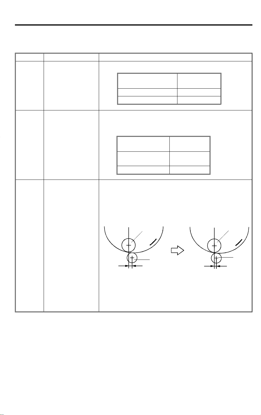
To ensure paper separation from the drum, the ink roller
has been shifted towards the paper feed table.
The distance L has been changed from 5.0 mm to 3.5 mm
(same as the C216 model).
C211 model
[A]
[B]
L
L = 5.0 mm L’ = 3.5 mm
3648 pixels
300 dots/inch
3072 dots
C224 model
[A]
[B]
L’
NOTE: The optional color drum for the C224 model
is commonly used for the C211 model.
(The distance L for the color drum is
4.5 mm.)
1-4
Page 8
4 July 1995
No. Item Remarks
4. Drum Connector
5. Ink Detection Board
6. Drum Shaft
7. Exit Pawl Air Pump
Main Board and
8.
9. Thermal Head Drive
12.
13. Air Knife Motor
14.
Image Processing
Board
Paper Table Drive
Motor
Pressure Plate
Position Sensors
ESSENTIAL DIFFERENCES BETWEEN C211/C212/C213
AND C224 MODELS
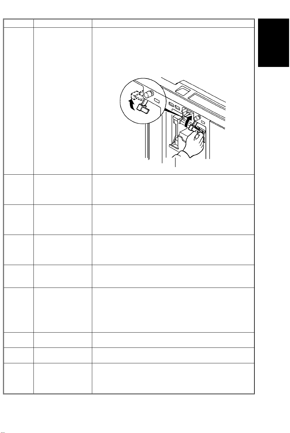
To ensure drum connection, a drum lock lever has been
added inside the front door. To remove the drum from the
machine, the drum release lever must be pulled up to
disconnect the drum connector. (Same as the C216
model.)
The location of the ink detection board has been changed
from the upper side to the right side of the drum shaft. The
ink type switch (SW901), which was not used (always set
at oil type), has been removed. (Same as the C216 model.)
To supply ink to the ink roller evenly, the second ink supply
hole (count from the front side) of the drum shaft is
covered with a strip of tape.
(Same as the C216 model.)
To ensure paper separation from the drum, the exit pawl
air pump system is standardized. (Same as the C216
model.) (The pump system can optionally be installed in
models of the C211 series.)
The main board and the image processing board have
been combined into one board.
The thermal head drive board has been removed. The
function of the board has been moved to the main board.
The thermal head voltage is directly applied from the
power supply unit. The main board applies the signal to the
PSU to supply thermal head voltage only during the master
making process. (Same as the C216 model.)
The paper table drive motor has been changed from an ac
motor to a dc motor.
The air knife motor has been changed from an ac motor to
a dc motor.
The pressure plate position switch and the full master
detecting switch have been eliminated.
Three photo-interrupters, upper and lower pressure plate
sensors and full master box sensor are used instead.
Overall
Information
1-5
Page 9

ESSENTIAL DIFFERENCES BETWEEN C211/C212/C213
AND C224 MODELS
No. Item Remarks
The master eject motor which had two functions: (one is to
15.
16 Skip Feed
17.
18.
Pressure Plate
Motor
Economy Function
(New Function)
Security Mode
(New Function)
drive the exit rollers, the other is to drive the pressure
plate) has been replaced by two motors; the master eject
motor and pressure plate motor. Due to this modification,
the master box capacity has been increased.
A user can select from 2 to 9 rotations of the drum while
one sheet of paper is fed.
If "Economy mode" is selected on the operation panel, a
lower thermal head energy is applied when a master is
made. As a result, the image will be lighter than normal
and ink consumption will be less.
"Secret mode" can be selected by changing DIP SW103-6.
If this mode is selected, the Print key is disabled after
turning the main switch off and on. (Only the "Master
making key" is available.)
4 July 1995
1-6
Page 10

4 July 1995 ELECTRICAL COMPONENT DESCRIPTIONS
3. ELECTRICAL COMPONENT
DESCRIPTIONS
INDEX
No.
Motors
Main Motor Drives paper feed, drum, printing and paper delivery
1
Vacuum Motor Provides suction so that paper is held firmly on the
4
7 ADF Drive Motor Feeds the original to the original transport section.
12 Original Transport Motor Transports the original to the scanner section.
20 Master Feed Motor Feeds the master to the drum.
22 Pressure Plate Motor Raises and lowers the pressure plate.
Air Knife Motor Rotates the fan to provide air to separate the paper
26
28 Master Eject Motor Sends used masters into the master eject box.
33 Cutter Motor Cuts the master.
Image Shift Motor Changes the timing between the paper feed roller
60
64 Paper Table Drive Motor Raises and lowers the paper table.
Solenoids
Original Pressure Solenoid Presses the original pressure plate down on the
11
Ink Supply Solenoid Releases the spring clutch to activate the ink supply
21
29 Master Eject Solenoid Opens the master clamp to eject the master.
Paper Feed Solenoid Releases the paper feed sector gear to rotate the
51
52 Printing Pressure Solenoid Moves the press roller against the drum.
Master Eject Clamper
56
Solenoid
Drum Lock Solenoid Prevents removal of the drum unit when the drum is
58
Master Feed Clamper
59
Solenoid
NAME FUNCTION
unit components.
transport belt.
leading edge from the drum.
and the drum to adjust the vertical image position.
originals.
pump.
paper feed roller.
Opens the master clamp to eject the master.
not at the home position.
Opens the master clamp to eject the master.
Overall
Information
Switches
Printing Density Switch Use to select the printing density corresponding to
6
14 ADF Safety Switch Check whether the ADF unit is set correctly or not.
Fluorescent Lamp Safety
18
Switch
19 Left Cutter Switch Detects when the cutter position is at the far left.
Master Eject Box Switch Checks whether the master eject box is installed
27
32 Right Cutter Switch Detects when the cutter position is at the far right.
the type and quality of the original.
Cuts the power for the fluorescent lamp when the
scanner is opened.
correctly or not.
1-7
Page 11

ELECTRICAL COMPONENT DESCRIPTIONS 4 July 1995
INDEX
No.
37 Front Door Safety Switch Checks whether the front door is set correctly or not.
38 Drum Safety Switch Checks whether the drum unit is set correctly or not.
41 Paper Table Safety Switch Checks whether the paper table is opened or not.
47 Test Switch Releases the cover safety functions. (NOTE:)
48 Main Switch Turns the power on or off.
Master Eject Unit Safety
49
Switch (220V machines only)
Master Eject Unit Safety
55
Switch (115V machines only)
Master Cutter Switch Informs the CPU to cut the master paper leading
62
65 Drum Rotation Switch Informs the CPU to rotate the main motor at 10 rpm.
Sensors
3 1st Paper Exit Sensor Detects misfeeds.
5 2nd Paper Exit Sensor Detects misfeeds.
Original Registration Sensor Detects misfeeds in the ADF, and synchronizes
9
10 2nd Original Sensor Detects when the original comes to the feed position.
13 1st Original Sensor Detects when the original is set in the ADF mode.
Lower Pressure Plate Sensor Informs the CPU if the pressure plate is at the lower
23
Full Master Box Sensor Informs the CPU if the master eject box is full of
24
Upper Pressure Plate Sensor Informs the CPU if the pressure plate is at the upper
25
30 Master Eject Sensor Detects master eject jams.
34 Master Buckle Sensor Detects master buckling.
Master End Sensor Informs the CPU when the plotter unit runs out of
35
Paper Table Height Sensor Detects when the paper table reaches the paper
40
Paper Table Lower Limit
42
Sensor
43 Printing Pressure Sensor Informs the CPU when printing pressure is applied.
Paper End Sensor Informs the CPU when the paper table runs out of
44
50 Drum Rotation Sensor Supplies timing pulses to the main board.
53 2nd Drum Position Sensor Checks the position of the drum.
57 1st Drum Position Sensor Checks the position of the drum.
NAME FUNCTION
Checks whether the master eject unit is closed
correctly or not. Cuts the ac power.
edge.
master feed with original feed.
limit position.
used masters.
limit position.
master roll.
feed position.
Detects when the paper table reaches the lowest
position.
paper.
Printer Circuit Board
16 CCD PCB Converts light into an electrical signal.
17 A/D Conversion PCB Converts analog signals into digital signals.
Main Control PCB Controls all machine functions both directly and
39
54 Ink Detection PCB Checks if the ink is present in the drum.
through other boards.
1-8
Page 12

4 July 1995 ELECTRICAL COMPONENT DESCRIPTIONS
INDEX
No.
63 Power Supply PCB Rectifies 100 V ac input and supplies dc voltage.
Counters
45 Copy Counter Keeps track of the total number of copies made.
46 Master Counter Keeps track of the total number of masters made.
Others
2 Transformer Steps down the wall voltage.
8 Fluorescent Lamp Exposes the original.
15 Fluorescent Lamp Stabilizer Controls the exposure lamp.
Reverse Roller Clutch Transfers master feed motor rotation to the reverse
31
36 Thermal Head Burns the image onto the master.
61 Encoder Converts 16 image positions to 4 bit data.
66 Operation Panel Interfaces the CPU and the operator.
NAME FUNCTION
roller at proper timing.
NOTE: The Master Eject Unit Safety Switch in the 220 V machines cannot
be disabled by this test switch.
Overall
Information
1-9
Page 13

SECTION 2
DETAILED DESCRIPTIONS
Page 14
4 July 1995 MASTER EJECT SECTION
1. MASTER EJECT SECTION
1.1 MASTER EJECT ROLLER DRIVE MECHANISM
[A]
[C]
[D]
[B]
Detailed
Descriptions
C224D500.img
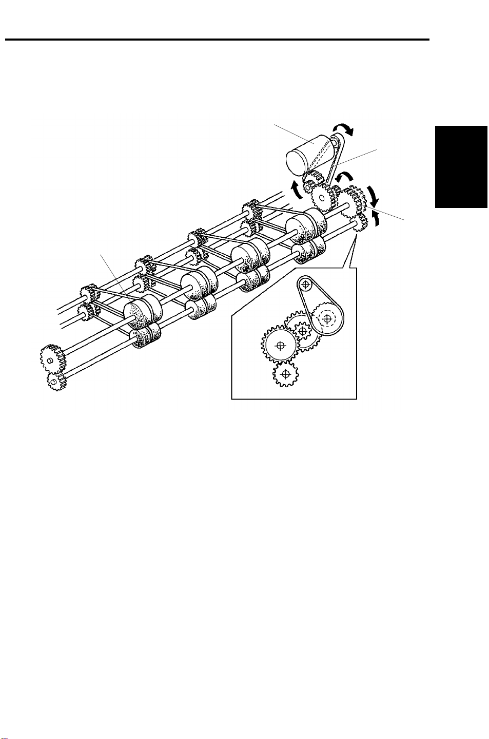
A dc motor [A] installed in the rear of the machine drives the master eject
rollers [B] through a timing belt [C] and gears [D] to eject used masters. The
master is transported between the upper and lower master eject rollers to be
ejected to the master eject box.
2-1
Page 15
MASTER EJECT SECTION 4 July 1995
1.2 PRESSURE PLATE UP/DOWN MECHANISM
[H]
[G]
[F]
[A]
[D]
[I]
[C]
[B]
[E]
C224D501.img
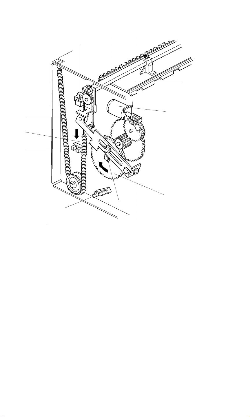
After the used master is transported to the master eject box, the master is
compressed by the pressure plate.
The pressure plate is driven by an independent dc motor. The pressure plate
motor [A] drive is transmitted to the gear [B] through gears, and the pin [C]
moves link [D] down until the lower pressure plate sensor [E] is actuated.
Spring [F] pulls down on the pressure plate [G] and the ejected master in the
master eject box is compressed. Then the pressure plate motor stays off until
the master making process is finished. Then the pressure plate motor starts
again to return the pressure plate to the upper position. The motor stops
when the upper pressure plate sensor [H] is actuated.
The machine detects that the master box is full if the full master box sensor [I]
is not actuated when the pressure plate goes down.
2-2
Page 16
4 July 1995 OPTICS
2. OPTICS
2.1 OVERALL
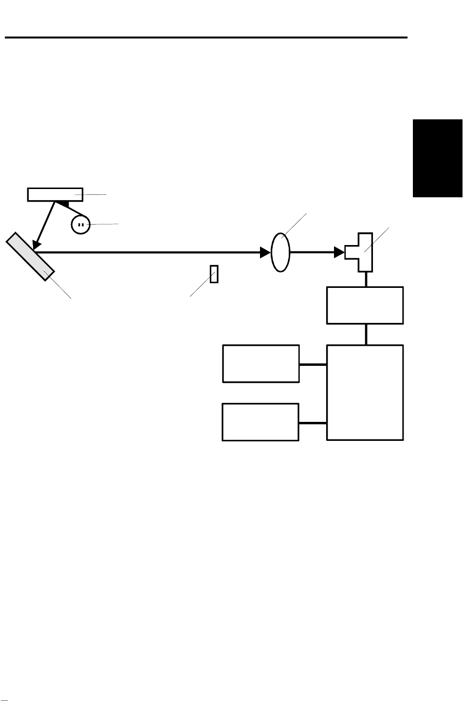
The CCD [A] which corresponds to a 300 dpi pixel density is used for the
C224 model.
Light reflected from the original goes to the CCD through a lens.
The CCD changes the light into an analog electrical signal which is changed
to 4-bit digital data in the A/D conversion PCB. The main control PCB
changes the 4-bit data into 1-bit data to drive the thermal head.
[E]
Detailed
Descriptions
[F]
[D]
[C]: Shading Plate
[D]: Mirror
[E]: Exposure Glass
[F]: Fluorescent Lamp
[C]
[B]
[A]
A/D Conversion
PCB
Thermal Head
Main
Control
PCB
Operation Panel
C224D502.wmf
2-3
Page 17
OPTICS 4 July 1995
2.2 THERMAL HEAD
(1) Specifications
The C224 model uses a 300 dpi thermal head.
Thermal head
• Width 256 mm
• Number of thermal head elements 3072 dots
• Density of thermal head elements 300 dpi
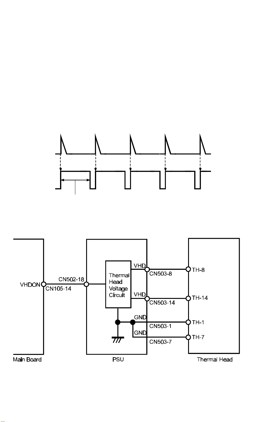
(2) Thermal Head Control
The PSU applies thermal head voltage which is adjusted in the factory to
match individual thermal head characteristics. The main control PCB
controls the thermal head to reproduce the image on the master.
ENLTRIG
ENL
Pulse width
C224D503.wmf
The thermal head energy is controlled by changing the pulse width.
The pulse is controlled by the ENL signal from the main board corresponding
to ENLTRIG from the image processing board.
C224D504.wmf
Thermal head voltage is applied from the PSU only during the master making
process. This is controlled by the VHDON signal (CN105-14) from the main
board.
2-4
Page 18

4 July 1995 DRUM
3. DRUM
3.1 DRUM CONNECTION MECHANISM
[D]
[A]
[C]
[B]
[F]
[E]
[E]
C224D505.img
Detailed
Descriptions
[D]
[H]
[G]
C224D506.img
When the drum release lever [A] in front of the machine is raised, the
connector [B] is pushed away from the drum by the bracket [C] through the
link [D], and is thus disconnected. The connector moves only horizontally due
to the guidance of the shafts [E]. The bracket [C] also pushes the drum lock
lever [F] to release the drum lock allowing the drum to be removed.
While the drum is out of home position, the drum lock solenoid [G] is
energized and the stopper [H] locks the link [D] so that it will not be pulled.
The solenoid is de-energized when the drum stops at the home position
(when the 1st drum home position sensor is actuated).
2-5
Page 19

PAPER DELIVERY 4 July 1995
4. PAPER DELIVERY
4.1 EXIT PAWL AIR PUMP MECHANISM
[A]
[C]
[A]
[D]
[B]
[C]
C224D507.img
The main motor drive is transmitted to the pump gear [A] through gears and a
timing belt [B]. The gear [A] rotates and drives the piston [C] back and forth.
The piston moves forward and pushes a jet of air out through the nozzle [D].
This jet of air helps to separate the paper from the drum.
2-6
Page 20

SECTION 3
INSTALLATION
NOTE: THE MACHINE MUST BE INSTALLED BY A CUSTOMER
SERVICE REPRESENTATIVE WHO HAS COMPLETED THE
TRAINING COURSES ON THIS MACHINE
Page 21

4 July 1995 INSTALLATION PROCEDURE
1. INSTALLATION PROCEDURE
Installation
1. Make sure that you have all the accessories listed below.
(1) Original Exit Tray..................................................................... 1
(2) Operating Instructions (USA and Asia version only)............... 1
(3) NECR ..................................................................................... 1
3-1
C224I501.img
Page 22

INSTALLATION PROCEDURE 4 July 1995
C224I502.img
[A]
C224I503.img
2. Mount the machine on the optional table (2 screws packed with the table).
3. Remove the strips of tape securing the covers and units as shown on the
right.
a. Open the paper feed tray. Then remove the cushion plate [A] from the
paper feed roller section.
b. Open the master delivery unit. Then remove the tape securing the
paper delivery guide plate.
3-2
Page 23

4 July 1995 INSTALLATION PROCEDURE
4. Remove the protective sheet [A]
from the drum unit.
a. Open the front door.
b. Take out the drum unit.
c. Remove the protective sheet
from the master clamper.
d. Reinstall the drum unit in the
machine.
e. Push down the drum lock
lever [B].
5. Install the original exit tray [C].
[B]
[A]
C224I504.img
Installation
[C]
6. Slide the scanner unit all the way
to the left, and take the master
spools [D] out.
C224I500.wmf
[D]
C224I514.wmf
3-3
Page 24

INSTALLATION PROCEDURE 4 July 1995
7. Loading Paper on the Paper Feed
Table
a. Open the paper feed table.
b. Stack the paper neatly on the paper
feed table.
c. Position the paper feed side plates
so that they lightly contact the paper
on both sides.
d. Position the paper delivery table for
the printing paper size, using the
scale on the table.
e. Position the paper delivery side
plate for the printing paper size,
using the scale on the table.
8. Installing the Master Roll
(Type VT-II-M)
a. While lifting the release lever, slide
the scanner unit to the left.
b. Attach a spool to each end of the
master roll.
c. Set the master roll in the machine.
NOTE: The vinyl side faces down.
d. Return the pressure release lever to
the original position.
C224I505.img
C224I506.img
e. Plug in the power cord and turn on
the main switch.
f. Press the Master Cut button.
g. Remove the cut master paper.
NOTE: Check that the master paper is
not bent or creased.
h. Close the scanner unit.
3-4
C224I507.img
C224I508.img
Page 25

4 July 1995 INSTALLATION PROCEDURE
9. Installing the Ink Cartridge
a. Open the front door and lower the
ink holder.
b. Remove the ink cartridge cap.
c. Insert the ink cartridge into the ink
holder and return the ink holder to
the original position.
d. Close the front door.
10. Idling
a. While holding down the "0" key on
the operation panel, press the
Reset key.
b. If + D blinks on the operation
panel, repeat the above procedure.
11. Test Printing
a. Adjust the original guide to match
the original size.
b. Place an original face down.
c. Input the desired number of prints
with the number keys and press the
Master Making key.
NOTE: With a new machine, the
master paper misfeed indicator
+ F blinks because there
is no master yet on the drum.
Press the Reset key, then
press the Master Making key.
C224I509.img
Installation
C224I510.img
d. After one sheet of paper is
delivered, make prints at the lowest
print speed (1) until the print image
density stabilizes. Use a test chart
to check for changes in the image
density.
e. Check the copy quality after the
image is stabilized.
C224I511.img
3-5
Page 26

SECTION 4
SERVICE TABLES
Page 27

4 July 1995 MAINTENANCE TABLES
1. MAINTENANCE TABLES
1.1 LUBRICATION POINTS
Lubricate after removing adhering ink and paper dust.
Lubrication Point Interval Type
Bearings for the drum drive shaft Yearly Oil
Bearing for each cam shaft Yearly Oil
Bearing for the main motor shaft Yearly Oil
Bearing for the speed reduction shaft Yearly Oil
Gears on the drum drive shaft Yearly Grease
Gears for each cam Yearly Grease
Paper feed sector gear Yearly Grease
Second feed sector gear Yearly Grease
Edge of each cam Yearly Grease
Master pressure plate groove Yearly Grease
Type of Oil and Grease
Oil: Motor Oil (SAE No.20)
Grease: Shell Albania No.2
1.2 USER’S MAINTENANCE
Please advise the customer to clean each item at suitable intervals.
Cleaning Point Interval Cleaner
Original platen cover At any time Cloth and water
Exposure glass At any time Cloth and glass cleaner
Paper feed rollers At any time Cloth, and soap and water (or alcohol)
Press roller At any time Cloth, and soap and water (or alcohol)
Tables
Service
4-1
Page 28

MAINTENANCE TABLES 4 July 1995
1.3 PERIODIC INSPECTION TABLE (EVERY 6 MONTHS)
Item/Location Step Inspection Standard
Original platen cover Cleaning Wipe off any stains with a soft cloth dampened
with ethyl alcohol.
Exposure glass Cleaning Wipe with a dry cloth.
Mirror/Sub mirror Cleaning Use a blower brush.
Platen roller Cleaning Wipe off paper powder with a cloth dampened with
water.
Sensors Inspection
and cleaning
Press roller Cleaning Wipe off the ink and paper powder with cloth
Drum surface Cleaning Wipe off the paper powder and ink which is forced
Master feed and
delivery
Paper feed and delivery Inspection Print a few sheets to ensure that paper is smoothly
Second paper feed
rollers
Original transport rollers Cleaning Wipe off paper powder with a cloth dampened with
ADF
Pull-out roller Cleaning Wipe off paper powder with a cloth dampened with
Original feed roller Cleaning Wipe off paper powder with a cloth dampened with
Separation blade Cleaning Wipe off paper powder with a cloth dampened with
Inspection The master should be properly fed and clamped,
Cleaning Wipe off ink and paper powder with a cloth
Check the performance of all the sensors.
Remove stains from sensors with dry cloth.
dampened with ethyl alcohol.
out from the trailing edges of the masters using a
cloth dampened with ethyl alcohol.
without generation of skew, folding, etc. The
master should also be properly delivered without
jam.
fed and delivered, without generation of skew,
folds, wrinkles, etc.
dampened with alcohol.
water.
water.
water.
water.
4-2
Page 29

4 July 1995 MAINTENANCE TABLES
1.4 TABLE OF PERIODIC INSPECTION (EVERY 12 MONTHS)
Item/Location Step Inspection Standard
Original platen cover Cleaning Wipe off stains with a soft cloth dampened with
ethyl alcohol.
Exposure glass Cleaning Wipe off stains with a soft cloth dampened with
ethyl alcohol.
Fluorescent lamp Cleaning Wipe with a dry cloth.
Mirror/Sub mirror Cleaning Use a blower brush.
Platen roller Cleaning Wipe off paper powder with a cloth dampened with
water.
Paper feed roller Cleaning Wipe off paper powder with a cloth dampened with
water and wipe off ink with a cloth dampened with
ethyl alcohol.
Separation roller Cleaning Wipe off paper powder with a cloth dampened with
water and wipe off ink with a cloth dampened with
ethyl alcohol.
Sensors Inspection
and cleaning
Master delivery rollers Cleaning Wipe off built up ink and paper powder on the
Master delivery belts Cleaning Wipe off built up ink and paper powder on the
Second paper feed
rollers
Press roller Cleaning Wipe off built up ink and paper powder on the
Drum surface Cleaning Wipe off the ink, which is forced out from the
Master feed and
delivery
Cleaning Wipe off built up ink and paper powder on the
Inspection The master should be properly fed and clamped
Check the performance of all the sensors.
Wipe off stains on the sensor with a dry cloth.
master delivery rollers using a cloth dampened
with ethyl alcohol.
master delivery belts using a cloth dampened with
ethyl alcohol.
second feed rollers using a cloth dampened with
ethyl alcohol.
press roller using a cloth dampened with ethyl
alcohol.
trailing edges of masters, and paper powder using
a cloth dampened with ethyl alcohol.
without generation of skew, folds, etc. The master
should also be properly delivered without jam.
Tables
Service
Paper feed and delivery Inspection Print a few sheets to ensure that paper is smoothly
fed and delivered without generation of skew,
folds, wrinkles, etc.
Original transport roller Cleaning Wipe off paper powder with a cloth dampened with
water.
Lubrication points Lubrication Lubricate the lubrication points in the lubrication
points list.
4-3
Page 30

MAINTENANCE TABLES 4 July 1995
Item/Location Step Inspection Standard
ADF
Pull-out roller Cleaning Wipe off paper powder with a cloth dampened with
water.
Original feed roller Cleaning Wipe off paper powder with a cloth dampened with
water.
Separation blade Cleaning Wipe off paper powder with a cloth dampened with
water.
4-4
Page 31

4 July 1995 MAINTENANCE TABLES
1.5 EXPECTED LIFE OF PARTS
NOTE: The main parts have the following expected life.
Target Copy Volume Range: Avg. 50,000 prints/month.
(Max. 100,000~Min. 20,000 prints/month)
Avg. 500 masters/month
Section Part Description Expected Life
Scanner Unit Fluorescent lamp
Original transport rollers
Master Feed Unit Thermal head
Cutter
Upper master feed rollers
Platen roller
Drum Unit Cloth screen 2 years or 1,200,000 prints
Paper Feed Unit Paper feed rubber side plate
Paper feed roller
Upper separation roller
Separation plate
Lower separation roller
Feed roller brake
Printing Unit Press roller 2 years or 1,200,000 prints
Delivery Unit Vacuum belts 2 years or 1,200,000 prints
ADF Unit Pull-out roller
Original feed roller
Separation blade
Original pressure plate
15,000 masters
1 year or 6,000 masters
30,000 masters
30,000 masters
1 year or 6,000 masters
30,000 masters
1,200,000 prints
6 months or 300,000 prints
600,000 prints
2,000,000 prints
1,000,000 prints
60,000 sheets
60,000 sheets
60,000 sheets
60,000 sheets
Tables
Service
1.6 SPECIAL TOOLS
Description Parts Number
Test chart 99992131
Resolution chart A0129110
Drum gauge C2009001
Image shifting gauge C2009002
4-5
Page 32

TABLE OF SERVICE CALL INDICATIONS 4 July 1995
2. TABLE OF SERVICE CALL INDICATIONS
Indication Trouble Possible cuses
E 01
E 02
E 04
E 05
E 06
E 09
E-10
E-11
E-12
Malfunction in the cutter section:
The cutter does not reach both right and left
cutter position switches within 2 seconds.
Malfunction in the paper table drive section:
The lower limit sensor or the paper table height
sensor status does not change even though the
paper table Up or Down signal is applied.
The temperature of the thermal head or the
power supply unit is high:
The temperature of the thermal head becomes
greater than 53°C.
Malfunction in the image shifting section:
All the encoder output signals are at the "H" level.
Mechanical lock:
The drum rotation sensor detects that the drum
rotation speed is abnormal.
Malfunction of the thermal head. 1) Defective thermal head
Malfunction in the thermal head drive section. 1) Defective main control
Image shift motor malfunction:
The encoder status does not change within 3
seconds after the encoder motor starts rotating.
Malfunction in the pressure plate drive section:
The loner pressure plate sensor is not actuated
within 8 seconds.
The upper pressure plate sensor is not actuated
within 4 seconds.
1) Drive wire cut
2) Drive section malfunction
3) No power supply
1) Drive worm gear broken
2) Mounting screw of the
worm gear broken
3) No power supply
1) Defective thermistor
2) Defective thermal head
3) Defective power supply
unit
1) Encoder connector of
the image shifting
section is disconnected.
2) Defective encoder
1) Mechanical lock
2) Main motor failure
2) Defective thermistor
3) Thermal head harness
broken
PCB
2) Thermal head drive wire
short circuit
1) Image shift motor lock
2) Image shift motor
harness broken
1) Pressure plate motor
lock
2) Pressure plate motor
harness broken
3) Pressure plate position
sensor malfunction
4-6
Page 33

4 July 1995 DIP SW, LED, VR, AND TP TABLES
3. DIP SW, LED, VR, AND TP TABLES
3.1 DIP SW TABLE (ON THE MAIN BOARD)
No. DIP SW Function Remarks Factory Setting
1 DPS101 Not Used OFF
Thermal Head
2 DPS102-1
3 DPS102-2
DPS103-1
4
DPS103-2
5 DPS103-3
6 DPS103-4
7 DPS103-5
8 DPS103-6
9 DPS103-7 Key Counter Turn on when installing the key counter. OFF
10 DPS103-8
DPS104-1
11
DPS104-2
DPS104-3
12 DPS104-4 Not Used OFF
13 DPS104-5 Not Used OFF
14 DPS104-6
15 DPS104-7
16 DPS104-8
Test
Dither Matrix
Selection
Skip Paper
Feed Setting
Initial Full
Master Check
Initial Print ON: Make two prints after making
Beeper
ON/OFF
Security
Function
On Line Turn on when installing the option
Reduction
Ratio
Compensation
Auto Class If this switch is on, in Memory/Class
Reduction
Ratio Selection
Class/Memory
Selection
Turn off to access test pattern mode.
(Refer to the Thermal Head Test
section.)
Turn off to select the 6 x 6 dither
matrix. (Image will be lighter if the 6 x 6
dither matrix is selected.)
ON: 4 x 4
OFF: 6 x 6
Select the number of drum rotation for
every print when the Skip Paper Feed
mode is selected. (See the skip paper
setting table on the next page.)
If this switch is on, when the main
switch is turned on, masters in the
master eject box are compressed once
to check if the master eject box is full.
a master.
OFF: Make one print after making
a master.
Turn on to sound the beeper.
If this switch is on, prints cannot be
made without making a new master
after turning the main switch off and on.
controller.
Used to adjust the reduction ratio in the
sub-scan direction. (Refer to Image
Magnification in the Sub-Scan
Direction Adjustment.)
mode, the next job starts 5 seconds
after the previous job is finished even if
the tape marker is not installed.
Select the reduction ratio setting.
ON: 93%, 75%, 64%.
OFF: 93%, 82%, 71%.
Select class or memory function.
ON: Memory
OFF: Class
ON
ON
DPS103-1: OFF
DPS103-2: OFF
OFF
OFF
OFF
OFF
OFF
OFF
A4 version: OFF
LT version: ON
ON
Tables
Service
4-7
Page 34

DIP SW, LED, VR, AND TP TABLES 4 July 1995
Skip Paper Setting Table
1 Sheet/
2 Rotations
DPS103-1 OFF ON OFF ON
DPS103-2 OFF OFF ON ON
1 Sheet/
3 Rotations
1 Sheet/
5 Rotations
1 Sheet/
8 Rotations
Skip paper setting can also be changed by key operation.
Press a number key while pressing the skip paper feed key to select the
number of rotations per print.
4-8
Page 35

4 July 1995 DIP SW, LED, VR, AND TP TABLES
3.2 LED TABLE
No. LED Function Remarks
1 LED101 (MSPD)
2 LED102 (PDLV) 2nd Paper Exit SN When paper is detected, the LED lights.
3 LED103 (ROLL) 1st Paper Exit SN When paper is detected, the LED lights.
4 LED104 (MDLV) Master Eject SN When a master is detected, the LED lights.
5 LED105 (INK)
Main Motor ON When the main motor turns on, the LED
lights.
Ink Detection When ink is detected, the LED lights.
NOTE: When the drum release lever is
raised, the drum connector is
disconnected and the the LED turns
off.
3.3 VR TABLE
No. VR Function
1 VR101 (MSPD) Main motor speed adjustment.
2 VR102 (PDLV) 2nd paper exit sensor adjustment.
3 VR103 (ROLL) 1st paper exit sensor adjustment.
4 VR104 (MDLV) Master eject sensor adjustment.
3.4 TEST PIN TABLE (Main Control PCB)
No. Test Pin Function
1 TP101 (DPLS) Drum rotation sensor output.
2 TP102 (PDLV) 2nd drum position sensor output.
3 TP103 (ROLL) 1st drum position sensor output.
4 TP104 (MDLV) Master eject sensor output.
5 TP105 (INK) Ink detection signal.
6 TP106 (GND) GND.
7 TP107 (GND) GND.
3.5 TEST PIN TABLE (A/D Conversion PCB)
No. Test Pin Function
1 TP600 GND.
2 TP601 Shift signal output (SH).
3 TP602 CCD output (OS).
4 TP603 Inverted and amplified CCD output.
5 TP604 Black level standard voltage output.
Tables
Service
4-9
Page 36

SERVICE PROGRAM TABLE 4 July 1995
4. SERVICE PROGRAM TABLE
4.1 HOW TO ACCESS I/O CHECK MODE
1. Turn on the main switch while holding down the Print Start key, Stop key,
and Clear key.
2. Press the Memory/Class key to select either "Input" or "Output".
Memory indicator "1" Input
Memory Indicator "0" Output
4-10
Page 37

4 July 1995 SERVICE PROGRAM TABLE
4.2 INPUT CHECK MODE
Counter
Indication
1-1
2-2
3-1
4-1
5-1
6-1
7-1
8-1
9-1
10-1
11-1
12-1
13-1
14-1
15-1
16-1
17-1
18-1
19-1
20-1
21-1
22-1
23-1
24-1
25-1
26-1
27-1
Component to be checked
ADF Safety Switch
1st Original Sensor
2nd Original Sensor
Original Registration
Paper End Sensor
Paper Table Lower Limit Sensor
Paper Height Sensor
Right Cutter Switch
Left Cutter Switch
Master Buckle Sensor
Master End Sensor
Ink Detection
Color Drum
Drum Safety Sensor
Master Eject Sensor
Upper Pressure Plate Sensor
Lower Pressure Plate Sensor
Master Eject Box Switch
Full Master Box Sensor
1st Paper Exit Sensor
2nd Paper Exit Sensor
Printing Pressure Sensor
1st Drum Position Sensor
2nd Drum Position Sensor
Master Cut Position Sensor
Key Counter Set
Not Used
Tables
Service
4-11
Page 38

SERVICE PROGRAM TABLE 4 July 1995
4.3 OUTPUT CHECK MODE
Counter
Indication
1-0
2-0
3-0
4-0
5-0
6-0
7-0
8-0
9-0
10-0
11-0
12-0
13-0
14-0
15-0
16-0
17-0
18-0
19-0
20-0
21-0
22-0
23-0
24-0
25-0
26-0
27-0
28-0
29-0
30-0
31-0
32-0
33-0
34-0
35-0
36-0
37-0
38-0
39-0
Output
ADF Motor is energized.
ADF Original Pressure Solenoid is energized.
Master Eject Motor is energized.
Pressure Plate Motor is energized.
Reverse Roller Clutch is energized.
Vacuum Fan Motor is energized.
Air Knife Motor is energized.
Key Counter counts up.
Master Counter counts up.
Total Counter counts up.
Ink Supply Solenoid is energized.
Drum Lock Solenoid is energized.
Printing Pressure Solenoid is energized.
Paper Feed Solenoid is energized.
Master Feed Clamper Solenoid is energized.
Master Eject Clamper Solenoid is energized.
Master Eject Solenoid is energized.
Paper Table Drive Motor is energized to moves the paper table down.
Paper Table Drive Motor is energized to moves the paper table up.
Relay for main motor reversing is energized.
Lamp is energized.
Cutter Motor is energized to move the cutter unit from front to rear.
Cutter Motor is energized to move the cutter unit from rear to front
Image Shifting Motor rotates in the (+) direction.
Image Shifting Motor rotates in the (--) direction.
Drum rotates at 10rpm.
Drum rotates at 20rpm.
Drum rotates at 60rpm.
Drum rotates at 75rpm.
Drum rotates at 90rpm.
Drum rotates at 105rpm.
Drum rotates at 120pm.
Original Transport Motor is energized.
Master Feed Motor is energized.
Thermal Head Energy is applied.
All the operation panel indicators are turned on.
Tape Maker (option) feeds out strips of paper.
Printing operation is done at 10rpm.
Simulates original transportation in ADF mode.
NOTE: 1. If the drum is rotated using output check mode 26-0 to 32-0,
the drum rotation speed (rpm) is displayed in the copy counter.
2. After selecting output check mode 35-0 and pressing the Print
Start key, the thermal head voltage is continuously applied
until the Stop key or the Clear key is pressed. The beeper
sounds while the thermal head energy is applied. Do not apply
thermal head voltage for a long time.
4-12
Page 39

4 July 1995 SERVICE PROGRAM TABLE
4.4 THERMAL HEAD TEST
The purpose of this mode is to distinguish whether the cause of the image
problem is located before or after image processing.
Output image: The normal output of this test pattern image mode is one
of the dither matrix patterns as illustrated below.
Master processing length:
Main scan (Horizontal) direction: Full width of the thermal head
Sub-scan (Vertical) direction: Same as the vertical size of
the original set on the original
table.
Test Pattern Image
Magnified Test Pattern Image
Test Pattern in
Line Mode
Test Pattern in
Photo Mode
C224M501.wmf
Thermal Head
Fluorescent Lamp
CCD
Original Feed
Motor
C224M500.wmf
A/D Conversion
PCB
Main Control
PCB
Master Feed
Motor
BA
This test pattern is generated by the image processing PCB.
C224M502.wmf
[Example] Problem: Vertical white lines appear on the print.
Possible Cause 1 If the same problem appears on the output
image from the thermal head in test pattern
image mode, the cause should be in area
B, as shown above.
Possible Cause 2 If the output image from the thermal head is
correct in test pattern mode but the output
image in the normal mode is incorrect, the
cause should be in area A, as shown
above.
Tables
Service
4-13
Page 40

SERVICE PROGRAM TABLE 4 July 1995
4.4.1 OPERATION: (To Enter Test Pattern Image Mode)
1) Remove the front cover.
2) Turn off DIP SW102-1 only when the power switch is off.
3) Turn on the main switch.
4) Press the Image Mode key to select the test pattern image.
Test pattern in line mode
Test pattern in photo mode
C224M503.wmf
5) Place an original on the original table.
CAUTION:
To prevent overheating of the thermal head, make the original as short
as possible. Any type of original is suitable as the test pattern being
used is in the image processing PCB memory.
6) Press the Master Making key and make prints.
7) After completion of the test pattern image mode, turn on DIP SW 102-1.
4-14
Page 41

4 July 1995 AVAILABLE OPTION/SUPPLY TABLE
5. AVAILABLE OPTION/SUPPLY TABLE
O: Standard combination
∆: Usable under certain conditions
X: Cannot be used
Masters Type 800 X
Type 900 X
VT-S X
VT-M X *NOTE1
VT-L X
VT-ΙΙ-M
Inks Black O
Color O
VT-Black-1000 X
Color Drums Color Drum
Color Drum Type 905
Color Drum VT2000-M O
Color Drum VT2000-LG X *NOTE3
Color Drum VT2000-S X *NOTE3
Color Drum VT3000-L X
Color Drum VT3000-S X
Others Cassette B4 X
Cassette VT3000-L X
Cassette VT3000-S X
Tape Marker Type 20 O
Priport Table O
Priport Table VT3000 X
O
∆ *NOTE2
∆ *NOTE2
Tables
Service
NOTE: 1. The VT-M master can be installed in the C224 model, however, a
weak image (sometimes blank) will appear.
This is because the VT-ΙΙ-M master is more sensitive than the
VT-M master.
2. The modified master clamper (P/N C2074948) must be installed.
3. The drum can be installed. However, the maximum image area is
limited depending on the drum screen size.
4-15
Page 42

SECTION 5
REPLACEMENT
AND ADJUSTMENT
Page 43

4 July 1995
1) The replacement and adjustment procedures not mentioned in the
following pages are identical to those of the C211, C212 and C213
models.
2) The purpose and procedure of the following adjustments are identical to
those of the C211, C212 and C213 models, however the adjustment
value or VR number is different.
•• PRINTING PRESSURE ADJUSTMENT
[B]
[A]
C224R511.img
Adjust the clearance [A] to be 14 ± 0.5 mm by turning the adjustment bolt [B].
•• PRINTING SPEED ADJUSTMENT
Adjust the drum speed by turning VR101 on the main board.
•• EXIT PAWL CLEARANCE ADJUSTMENT
Drum
0.5 + 0.2 mm
-- 0 mm
C224R500.wmf
Adjust the exit pawl clearance so that the distance between the exit pawl and
the drum is between 0.5 and 0.7 mm.
•• FIRST PAPER EXIT SENSOR ADJUSTMENT
Adjust the 1st paper exit sensor sensitivity by turning VR103. Check the
sensor status with LED103.
Adjustment
Replacement
•• SECOND PAPER EXIT SENSOR ADJUSTMENT
Adjust the 2nd paper exit sensor sensitivity by turning VR102. Check the
sensor status with LED102.
5-1
Page 44

OPTICS ADJUSTMENT 4 July 1995
1. OPTICS ADJUSTMENT
The method of the optics adjustment is the same as the C211, C212 and
C213 models. However, the wave shape is not exactly the same because the
pixel density of the C224 model is different from that of the C211, C212 and
C213 models.
Necessary Tools
1) Facsimile Text Chart R-21 (99992131)
2) Resolution Chart (A0129110)
3) Oscilloscope
1.1 PREPARATION FOR ADJUSTMENT
1. Remove the original table and the original table cover.
2. Connect the terminals of the oscilloscope to the following test pins on the
A/D conversion board.
Oscilloscope Text Pin
Channel 1 TP603
Channel 2 (Black level
standard voltage)
GND TP600
C224R515.img
3. Access "I/O Check Mode".
• Turn on the main switch while holding the Print Start key, Stop key
and Clear key on the operation panel.
TP604
4. Set "21" in the copy counter using the number keys, and set "0" in the
memory/class display by pressing the memory/class key
5. Press the Print Start key to turn on the fluorescent lamp.
5-2
Page 45

4 July 1995 OPTICS ADJUSTMENT
1.2 BLACK LEVEL ADJUSTMENT
TP603 wave shape
TP604 standard black level
TP604 standard black level
TP603 wave shape
C24R506.wmf
Adjust VR601 so that the black level at TP603 is the same as the standard
black level (1.4 V±0.03 V).
1.3 SHADING ADJUSTMENT
B
A
B/A ≥ 60%
C224R505.wmf
Adjust the shading plate position so that the wave is shaped as shown above.
Adjustment
Replacement
5-3
Page 46

OPTICS ADJUSTMENT 4 July 1995
1.4 SCAN LINE POSITION ADJUSTMENT
C224R509.img
C224R501.wmf
Set the R-21 test chart so that the 1 mm black line is positioned 16 mm away
from the edge of the lower original guide plate.
Adjust the CCD board position so that the shape of the wave is similar to the
above illustration.
1.5 READING START POSITION ADJUSTMENT (In The Main Scan Direction)
[E]
L = L’
L
L’
[D]
C224R514.img
C224R502.wmf
Set the test chart so that the center line, located at the leading edge of the
test chart, is positioned above the original leading edge sensor actuator.
Then feed the test chart so that the center line can be read.
Adjust the CCD board position so that the above wave is displayed.
5-4
Page 47

4 July 1995 OPTICS ADJUSTMENT
1.6 FOCUS ADJUSTMENT
C224R503.wmf
B
•
x 100 ≥ 20%
A
C224R508.img
• Amplitude "B" (difference between white and black levels) must be a
maximum.
Position the resolution chart so that the 300 DPI section can be read. Adjust
the lens position so that the above wave appears.
1.7 REDUCTION RATIO ADJUSTMENT
Cross point
C224R504.wmf
Adjustment
Replacement
C224R513.img
Position the resolution chart so that the 300 DPI section can be read. Adjust
the lens block position so that the cross points are fewer than 8.
5-5
Page 48

OPTICS ADJUSTMENT 4 July 1995
1.8 WHITE LEVEL ADJUSTMENT
2.0 ± 0.1 V
C224R507.wmf
Adjust VR600 on the AD conversion board so that the maximum level is 2.0 ±
0.1 V.
1.9 IMAGE MAGNIFICATION IN THE SUB-SCAN DIRECTION ADJUSTMENT
Adjust the magnification ratio in the sub-scan direction using DIP103-1, 2, 3
on the main board, so that the printed image length is 100% ± 0.5%
compared with the original image length.
--DIP SW/Correction Ratio --
DPS 104 Original Length
1 2 3
OFF OFF OFF 100%
OFF ON OFF 99.5%
OFF OFF ON 99.0%
OFF ON ON 98.5%
ON OFF OFF 100%
ON ON OFF 100.5%
ON OFF ON 101.0%
ON ON ON 101.5%
Print Image Length
X 100
5-6
Page 49

4 July 1995 THERMAL HEAD VOLTAGE ADJUSTMENT
2. THERMAL HEAD VOLTAGE ADJUSTMENT
Purpose: To maintain master making quality and extend the lifetime of the
thermal head.
NOTE: This adjustment is always required when the thermal head or
power supply board is replaced.
[A]
[B]
C224R512.wmf
1. Remove the rear cover and the right cover and right cover of the machine.
2. Disconnect the connector [A] from the plotter unit.
3. Check the voltage noted on the decal, located on the thermal head.
(The voltage varies with each thermal head.)
4. Access "I/ Check Mode".
• Turn on the main switch while holding the Print Start, Stop and Clear
keys.
5. Input 35 in the copy counter using the number keys, and set "0" in the
Memory/Class display by pressing the Memory/Class key.
6. Press the Print Start key to apply the thermal head voltage.
7. Confirm that the voltage between one of the VHD terminals and one of
the ground terminals of CN503 is at the level specified on the decal
(Within + 0 V ,-- 0.1 V).
8. If it is not, adjust VR3 on the power supply board.
NOTE: Press the stop key to stop applying the thermal head voltage.
Do not keep the thermal head voltage on for a long period.
Adjustment
Replacement
5-7
Page 50

AIR PUMP TIMING ADJUSTMENT 4 July 1995
3. AIR PUMP TIMING ADJUSTMENT
[B]
[B]
[A]
[D]
[C]
C224R510.img
Purpose: To ensure that the paper exit pawl air pump produces a jet of air
at the proper time.
1. Remove the rear cover.
2. Set the drum in the home position.
3. Confirm that the mark [A] on the pump drive gear [B] is right over the gear
shaft [C].
4. If incorrect, remove the support plate [D] (5 screws) and reposition the
gear.
5. Rotate the drum to the home position and do step 3 again.
5-8
Page 51

ELECTRICAL COMPONENT LAYOUT
10
9
11
8
13
14
12
7
6
15
16
17
18
1
2
3
5
4
C224S500.wmf
Page 52

28
27
26
29
25
30
31
24
32
33
34
35
36
19
20
21
22
23
C224S501.wmf
Page 53

55
54
53
56
52
51
57
50
58
49
59
48
60
47
61
46 45
62
63
64
65
66
37
38
39
40
41
42
43
44
C224S502.wmf
Page 54

ELECTRICAL COMPONENT DESCRIPTIONS
INDEX
No.
Motors
1 Main Motor A-7
4 Vacuum Motor B-16
7 ADF Drive Motor J-7
Original Transport
12
Motor
20 Master Feed Motor D-5
22 Pressure Plate Motor B-10
26 Air Knife Motor B-10
28 Master Eject Motor B-10
33 Cutter Motor B-9
60 Image Shift Motor B-15
Paper Table Drive
64
Motor
Solenoids
Original Pressure
11
Solenoid
21 Ink Supply Solenoid B-12
Master Eject
29
Solenoid
51 Paper Feed Solenoid J-12
Printing Pressure
52
Solenoid
Master Eject
56
Clamper Solenoid
58 Drum Lock Solenoid B-14
Master Feed
59
Clamper Solenoid
Switches
Printing Density
6
Switch
14 ADF Safety Switch I-7
Fluorescent Lamp
18
Safety Switch
19 Left Cutter Switch B-9
Master Eject Box
27
Switch
32 Right Cutter Switch B-9
Front Door Safety
37
Switch
38 Drum Safety Switch B-8
NAME
LOCATION
P to P
J-8
A-7
J-6
B-10
J-12
J-13
J-14
G-8
I-5
B-11
B-7
INDEX
No.
Paper Table Safety
41
Switch
47 Test Switch B-3, B-6
48 Main Switch A-2
Master Eject Unit
49
Safety Switch (115 V
machines only)
Master Eject Unit
55
Safety Switch (220 V
machines only)
62 Master Cutter Switch B-9
Drum Rotation
65
Switch
Sensors
1st Paper Exit
3
Sensor
2nd Paper Exit
5
Sensor
Original Registration
9
Sensor
10 2nd Original Sensor I-5
13 1st Original Sensor I-6
Lower Pressure
23
Plate Sensor
Full Master Box
24
Sensor
Upper Pressure
25
Plate Sensor
30 Master Eject Sensor B-11
Master Buckle
34
Sensor
35 Master End Sensor B-9
Paper Table Height
40
Sensor
Paper Table Lower
42
Limit Sensor
Printing Pressure
43
Sensor
44 Paper End Sensor J-12
Drum Rotation
50
Sensor
2nd Drum Position
53
Sensor
1st Drum Position
57
Sensor
NAME
P to P
LOCATION
B-14
B-15
B-16
B-11
B-11
B-11
J-11
J-11
J-12
B-13
B-13
B-13
A-6
B-3
I-6
B-8
Page 55

INDEX
No.
Printer Circuit Board
16 CCD PCB I-3
17 A/D Conversion PCB H-4
39 Main Control PCB F-7
54 Ink Detection PCB C-13
63 Power Supply PCB G-1
Counters
45 Copy Counter J-13
46 Master Counter J-13
Others
2 Transformer B-2
8 Fluorescent Lamp K-4
Fluorescent Lamp
15
Stabilizer
Reverse Roller
31
Clutch
36 Thermal Head C-3
61 Encoder B-14
66 Operation Panel I-9
NAME
LOCATION
P to P
J-4
B-9
 Loading...