

Page 1

Technical Bulletin No. RTB-001
SUBJECT: To disable ink detection circuit DATE: Aug. 31, ’93
PAGE: 1 of 1
PREPARED BY: J. Mochizuki
CHECKED BY:
CLASSIFICATION:
Action Required
Troubleshooting
Retrofit Information
The ink detection circuit can be disabled if the main switch is turned on while both the
Auto Cycle key and the Reset key are pressed. If this mode is accessed, prints can be
made even though the ink detection pin is not in contact with the ink on the ink roller.
When the main switch is turned off, this condition is erased.
This function serves to remove the ink inside the drum.
The software of the main PCB ROM includes this function from the first mass production.
Revision of service manual
Information only
Other
FROM: Copier Technical Support Section
MODEL:
Priport VT1730
Ges 5303 / Rex 1220
NSA CP303
Page 2
Technical Bulletin No. RTB-002
SUBJECT: Master Feed Jams DATE: Aug. 31, ’93
PAGE: 1 of 1
PREPARED BY: J. Mochizuki
CHECKED BY:
CLASSIFICATION:
Action Required
Troubleshooting
Retrofit Information
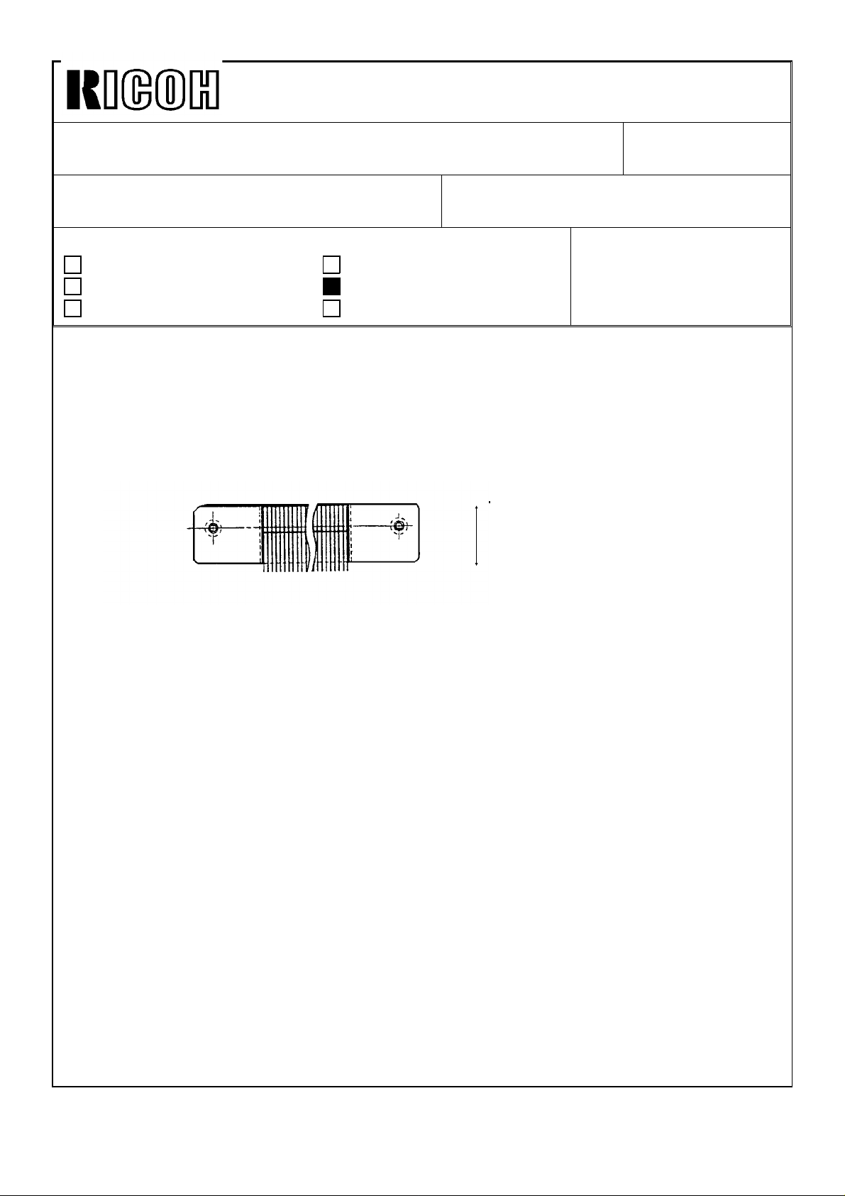
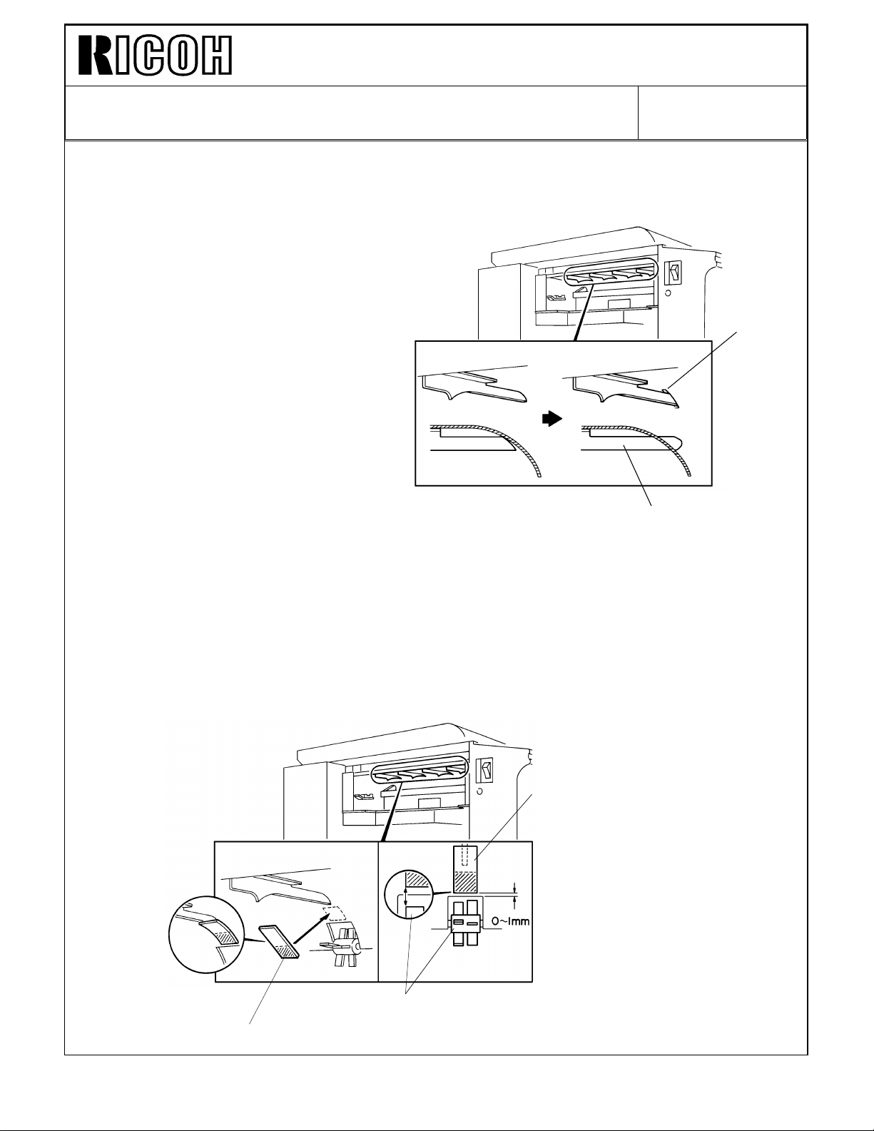
It was found that the antistatic brush sometimes interferes with master transportation and
causes master feed jams. To ensure smooth master feed, the position of the antistatic
brush [A] sticking on the inner cover [C] has been changed.
The sticking position is as shown below. Even if the antistatic brush does not contact the
master surface, it functions to remove electrostatic charges on the master.
[B]
Revision of service manual
Information only
Other
[A]
FROM: Copier Technical Support Section
MODEL:
Priport VT1730
Ges 5303 / Rex 1220
NSA CP303
20.5 →19.0
The cut-in serial numbers are as follows:
VT1730 USA version: C3223060020
Europe/Asis version: C3223070061
Ges5303/Rex1220/
NSACP303 USA version: 50723070001
Europe/Asis version: 50713070001
The antistatic brush assembly has been registered as a service part (C2174064). Please
refer to MB No. 11.
Page 3
Technical Bulletin No. RTB-003
SUBJECT: Paper feed pressure DATE: Aug. 31, ’93
PAGE: 1 of 1
PREPARED BY: J. Mochizuki
CHECKED BY:
CLASSIFICATION:
Action Required
Troubleshooting
Retrofit Information
When 500 sheets of standard paper (80g/m2) is set on the paper table, paper misfeeds
would occur. This is because not enough feed roller pressure is applied due to friction
between the paper stack (leading edge side) and the lower paper feed guide which guides
the leading edge of the paper stack.
In this case, advise your customer to change the position of the pressure adjustment
levers, as shown below, to increase paper feed pressure.
Revision of service manual
Information only
Other
FROM: Copier Technical Support Section
MODEL:
Priport VT1730
Ges 5303 / Rex 1220
NSA CP303
We confirmed that even if the pressure adjustment levers are in the lower position, normal
paper (70g/m to 200g/m) would be fed properly. So from August ’93 production, the
pressure adjustment levers have been set in the lower position (stronger pressure) in the
factory.
However, when paper multifeeds occur and the levers are lowered (it seems to occur very
rarely) it is possible that the problem mentioned above may still occur. Therefore, as a
permanent solution, we are looking for a more suitable tension for the feed pressure
springs.
Page 4
Technical Bulletin No. RTB-004
Rib
Gap
Guide
Plate
SUBJECT: Master Eject Jams DATE: June 15, ’94
PAGE: 1 of 3
PREPARED BY: H. Kokubo
CHECKED BY: S. Hamano
CLASSIFICATION:
Action Required
Troubleshooting
Retrofit Information
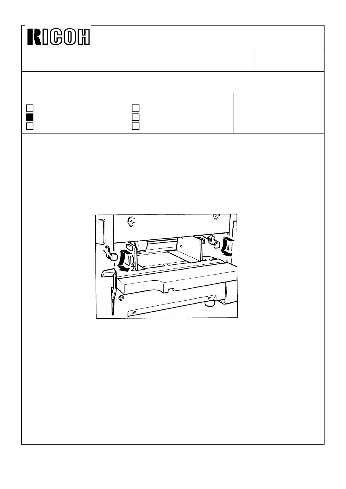
Symptom
1. Frequent master eject jams at location “F”.
2. The master wraps around the upper and/or lower master eject rollers.
3. “F” jam cannot be reset because the actuator (feeler) of the master eject sensor
remains pushed down by the pressure plate. (The actuator comes under the pressure
plate.)
Cause
Revision of service manual
Information only
Other
FROM: 2nd Technical Support Section
MODEL:
Priport VT1730/
Ges 5303 / Rex 1220/
Nsa CP303
Rib
There are 4 ribs to guide the ejected
master in the master eject unit. There
is a small gap at the leading edge of
the ribs against the guide plate.
Due to a part variation, if the gap is too
big, the master tends to be caught by
the ribs. A jam or other problems may
occur as per the following sequence:
----- Continued -------------------------------
OK
NG
Page 5
Technical Bulletin No. RTB-004
Gap
SUBJECT: Master Eject Jams DATE: June 15, ’94
PAGE: 2 of 3
1. While the master is being removed from the
drum, the leading edge of the master goes
properly into the master eject unit. At this point,
however, while the pressure plate moves to
compress the master in the eject box, the middle
part of the master tends to rub against the ribs.
If there are any gaps, the master is caught by
the ribs. (The master therefore remains caught
by the ribs.)
2. If no jam is detected by the machine after the
above situation has occurred, the machine can
carry out the next master eject. However, the
next ejected master interferes with the master
caught by the ribs and is stopped just behind the
eject rollers.
Master
Stopped Master
Eject Roller
As result, “F” jam will be indicated. Otherwise, if
there is no space for the master to proceed (due
to the previous master jam), the master is again
caught by and wraps around the eject rollers. If
the master is stopped just on the master eject
sensor, the sensor feeler remains pushed down
while the pressure plate is traveling. After the
pressure plate returns to its home position, the
sensor feeler comes under the plate. (“F” jam is
then indicated and cannot be reset.)
Page 6
Technical Bulletin No. RTB-004
Slot in the
Guide Plate
SUBJECT: Master Eject Jams DATE: June 15, ’94
PAGE: 3 of 3
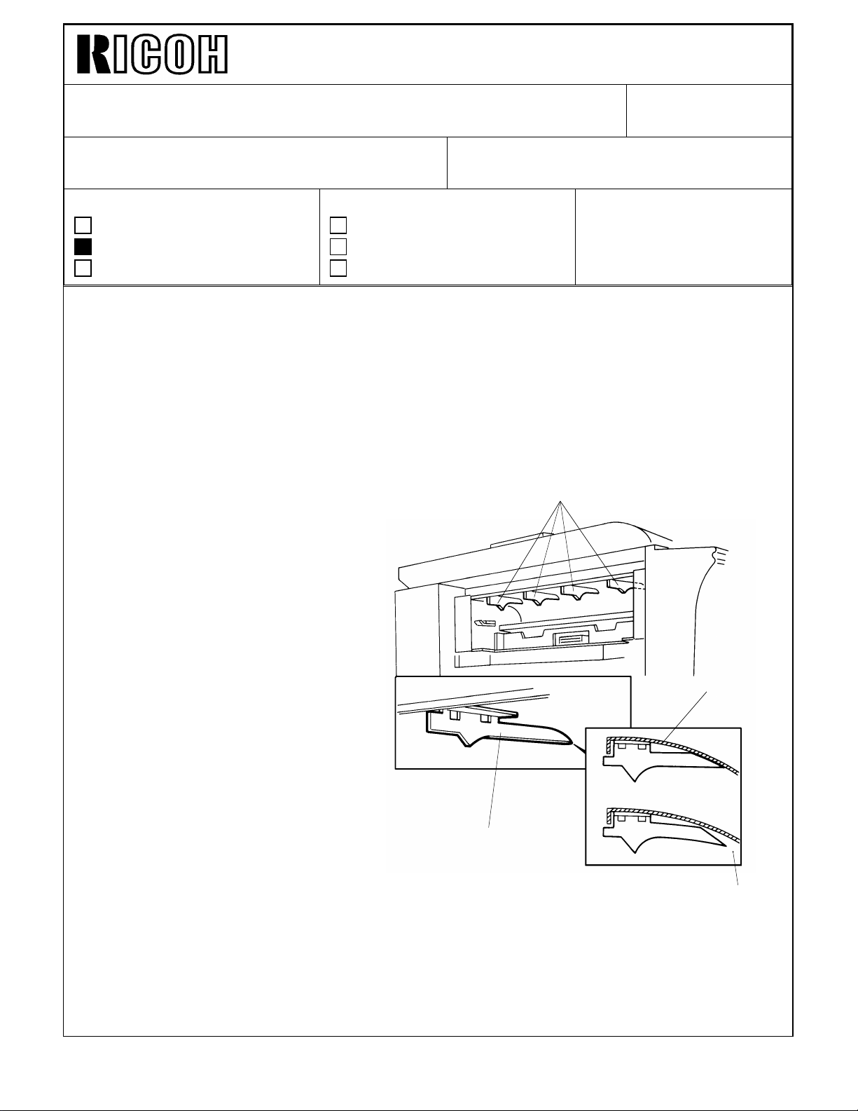
Solution 1 (For the mass production units)
The ribs fixed (welded) to the guide
plate have been changed as shown to
prevent any gap at the leading edge.
The part number of the guide plate
(Guide Plate - Eject Unit) has been
changed from #C2173565 to
#C2173567.
The new guide plate will be applied into
the production from June 1994.
New Rib
Solution 2 (For the field units)
As a solution for the field units, a mylar strip (Guide Mylar - 15 x 33 mm: P/N C2179500)
has been registered as a service part. Install the mylar strips on the leading edge of the 4
ribs to cover the gap as shown.
NOTE: 4 mylars are required for one unit.
Guide Mylar - 15 x 33 mm
Upper Eject Roller
Guide Mylar - 15 x 33 mm
Page 7
Technical Bulletin No. RTB-005
SUBJECT: Ink Pump Improvement DATE: Nov. 15, ’95
PAGE: 1 of 2
PREPARED BY: H. Kokubo
CHECKED BY: M. Iwasa
CLASSIFICATION:
Action Required
Troubleshooting
Retrofit Information
N810: Ricoh VT1730/Gestetner 5303/RexRotary 1220/nashuatec CP303/ABDICK 6120
N810-II: Ricoh VT1800/Gestetner 5304/RexRotary 1222/nashuatec CP304/ABDICK 6130
Information for the N810-II starts from this bulletin. RTB’s number 1 to 4 are for the
N810 only.
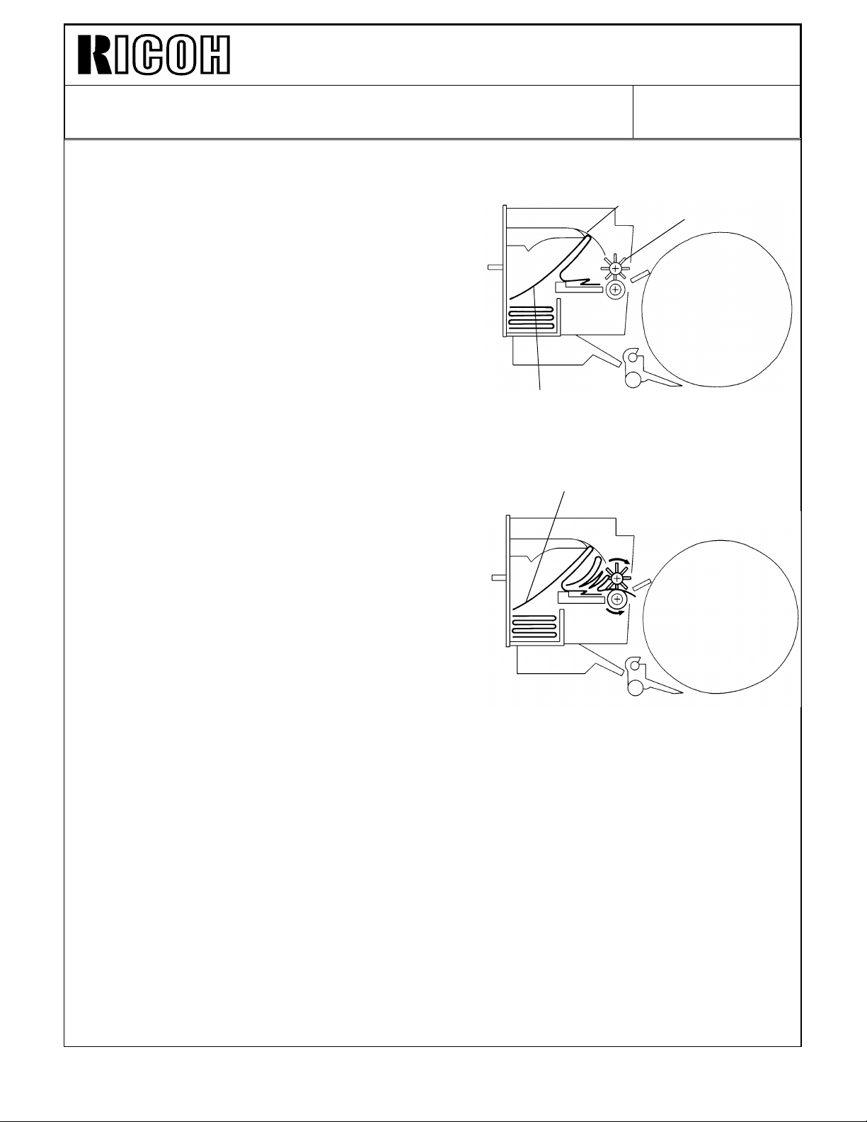
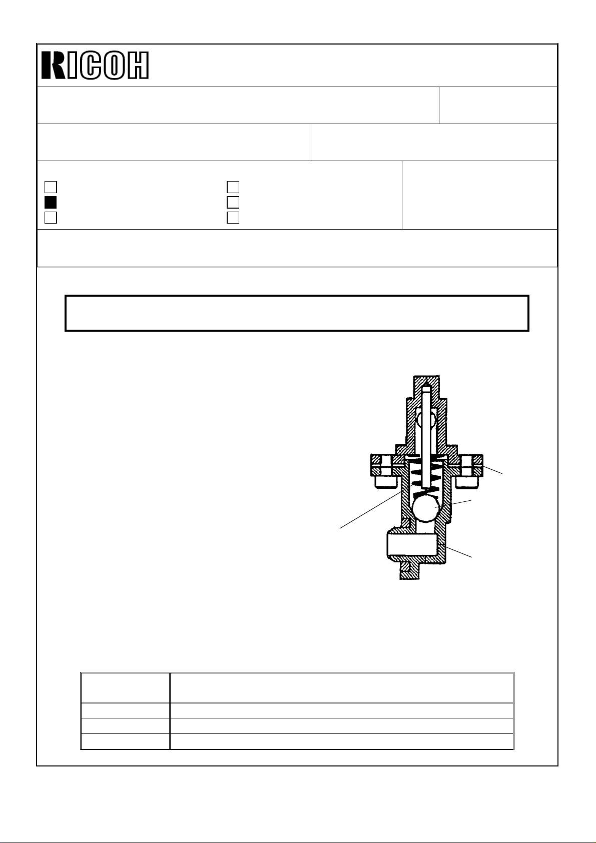
To ensure that all ink in the cartridge is supplied,
a spring has been added inside the ink
pump as shown to the right. The spring
ensures that the small ball, which is used as a
valve, is pushed back properly.
Revision of service manual
Information only
Other
FROM: 2nd Technical Support Section
MODEL:
Priport N810/N810-II
This modification has been applied from the
September 1995 production runs of all
Priport series models. The part numbers of
the ink pump assemblies remain the same.
(Note that the N850 and RN925 have been
using the new type from the first mass
production.)
There are three types of ink pump. They
are the NA/NB type that can hold the
1000 cc ink cartridge, the N type that can
hold the 600 cc ink cartridge only, and the
N810 type for the N810 and N810-II
only. See the following table for the
applicable models.
TYPE OF
INK PUMP
NA/NB NA-2, NA-3, NB-2
N N865, N860, N915, N935, N955, and all SS series models.
N810 N810, N810-II
APPLICABLE MODELS
Packing
Valve
Newly Added
Spring
Socket
Cross-section of the Bottom Part
of the Ink Pump
Page 8

Technical Bulletin No. RTB-005
SUBJECT: Ink Pump Improvement DATE: Nov. 15, ’95
PAGE: 2 of 2
There are two types of spring for these three types of the ink pump. The part numbers are:
C222 4710 (Pump Spring - 21 mm) : For the NA/NB type ink pump.
C224 4715 (Pump Spring - 13 mm) : For the N and N810 type ink pumps.
SOLUTION IN THE FIELD
For the field machines, you can install the spring after removing the socket (with two
screws). (It takes longer to replace the whole pump assembly.)
CAUTION: When you remove the socket, ink will leak. Be sure to place absorbant
material to prevent the floor from becoming dirty with ink.
NOTE: 1. There is a packing between the socket and housing (see the illustration on the
previous page). If it is damaged, you may have to replace the packing at the same
time. (Normally, this is not required.) The part number is:
C200 4827 (Packing - Pump Socket)
2. A rubber packing is used as shown below in order to ensure that the nozzle of
the ink cartridge tightly contacts the pump socket. Check if this part is dislocated.
The rubber packing used in the N810, the N865, and the other later models is
adhered with glue, but it is not adhered for the other older models.
C200 4826
(Pump Rubber)
Page 9

Technical Bulletin No. RTB-006
SUBJECT: Thermal Head Removal Procedure for N810-II DATE: Mar. 31, ’96
PAGE: 1 of 7
PREPARED BY: H. Kokubo
CHECKED BY: M. Iwasa
CLASSIFICATION:
Action Required
Troubleshooting
Retrofit Information
N810: Ricoh VT1730/Gestetner 5303/RexRotary 1220/nashuatec CP303/ABDICK 6120
N810-II: Ricoh VT1800/Gestetner 5304/RexRotary 1222/nashuatec CP304/ABDICK 6130
This bulletin is to inform you of the thermal head removal procedure, which is unique to
the N810-II but has not been described in the service manual.
At the same time, this is to inform you that a modification will be implemented into the
production to make the removal procedures easier. The details of the modification are as
follows:
A cutout has been made in the rear side (non-operation side) frame of the plotter
unit. (The part number: C2174102, remains the same, but all service parts are the
new type only.) This enables the removal of the thermal head (with the bracket)
without having to forcibly spread out the side frames. Refer to the new thermal
head removal procedure.
Revision of service manual
Information only
Other
FROM: 2nd Technical Support Section
MODEL:
Priport N810/N810-II
(N810-II Only)
This modification will be applied from the April 1996 production run.
Add the following pages of the new and old procedures for the thermal head removal to
your service manual.
Page 10

Technical Bulletin No. RTB-006
SUBJECT: Thermal Head Removal Procedure for N810-II DATE: Mar. 31, ’96
PAGE: 2 of 7
THERMAL HEAD REMOVAL PROCEDURE
[C]
[A]
[B]
CAUTION: If the thermal head has been replaced with a new one, the input voltage
must be readjusted. Follow the "THERMAL HEAD VOLTAGE ADJUSTMENT"
section in the service manual.
1. Turn off the main switch and disconnect the power plug.
2. Remove the plotter unit. (Refer to the "PLOTTER UNIT REMOVAL" section in the
service manual.)
3. Remove the platen roller cover [A].
4. Lift the platen roller release lever [B] up until it locks. Then, unhook the lock levers and
remove the platen roller [C].
Page 11

Technical Bulletin No. RTB-006
[E]
[F]
SUBJECT: Thermal Head Removal Procedure for N810-II DATE: Mar. 31, ’96
PAGE: 3 of 7
[D]
5. Remove the thermal head cover [D], then remove the release lever [E].
6. Remove the two springs [F].
[H]
[G]
7. Remove the two guide plate [G].
8. Remove the cutter unit [H].
Page 12

Technical Bulletin No. RTB-006
[M]
[J]
SUBJECT: Thermal Head Removal Procedure for N810-II DATE: Mar. 31, ’96
PAGE: 4 of 7
[L]
(B)
[K]
[M]
(A)
[I]
9. Remove the grounding screw [I].
10. Disconnect the connectors [J] from the thermal head.
11. While spreading the both side frames outward, unhook the pins on both sides of the
thermal head bracket [K] and remove the bracket (with the thermal head).
12. Remove the two screws [M] and you can remove the thermal head [L].
Page 13

Technical Bulletin No. RTB-006
SUBJECT: Thermal Head Removal Procedure for N810-II DATE: Mar. 31, ’96
PAGE: 5 of 7
THERMAL HEAD REMOVAL PROCEDURE (New Procedure)
[A]
[B]
[C]
CAUTION: If the thermal head has been replaced with a new one, the input voltage
must be readjusted. Follow the "THERMAL HEAD VOLTAGE ADJUSTMENT"
section in the service manual.
1. Turn off the main switch and disconnect the power plug.
2. Open the scanner unit.
3. Remove the platen roller cover [A].
4. Lift the platen roller release lever [B] up until it locks. Then, unhook the lock levers and
remove the platen roller [C].
Page 14

Technical Bulletin No. RTB-006
[E]
SUBJECT: Thermal Head Removal Procedure for N810-II DATE: Mar. 31, ’96
PAGE: 6 of 7
[D]
[F]
5. Remove the thermal head cover [D], then remove the release lever [E].
6. Remove the two springs [F].
[H]
7. Remove the cutter unit [H].
Page 15

Technical Bulletin No. RTB-006
SUBJECT: Thermal Head Removal Procedure for N810-II DATE: Mar. 31, ’96
PAGE: 7 of 7
[M]
[K]
[I]
[L]
[J]
8. Remove the grounding screw [I].
9. Disconnect the connectors [J] from the thermal head.
10. Unhook the pins on non-operation sides of the thermal head bracket [K] through the
cutout [L] and remove the bracket (with the thermal head).
NOTE: The cutout [L] has been newly added.
11. Remove the two screws and you can remove the thermal head [M].
Page 16

PAGE: 1 OF 6
Technical Bulletin No. RTB-007
SUBJECT: Paper Leading Edge Dirty with Ink ISSUED ON: August 31, 1996
CLASSIFICATION:
Action Required
Troubleshooting
Retrofit Information
Revision of service manual
Information only
Other
ISSUED BY:
H. Kokubo,
Priport Service Planning Section
MODEL: PRIPORT
N810: Ricoh VT1730/Gestetner 5303/RexRotary 1220/nashuatec CP303/ABDICK 6120
N810-II: Ricoh VT1800/Gestetner 5304/RexRotary 1222/nashuatec CP304/ABDICK 6130/SVN3100DNP
SYMPTOM:
During a long printing run, unwanted ink appears at the leading edge of copies. At first, it
is very hard to see, but it becomes more visible as the printing continues.
CAUSE:
Due to rough edges of the paper, the master wrapped around the drum becomes
damaged.
Just when the leading edge of the paper reaches under the drum, it is pressed against
the drum surface, so that the master is wrapped around by the press roller. Due to this
repeating action, the master’s surface is gradually torn where the paper leading edge
contacts it.
Also, if the paper generates a lot of paper dust, this is accumulated on the press roller
surface and damages the master in the same manner.
Normally, even if the master is damaged, there is no ink around the area beneath the
master where the paper leading edge contacts it (there are no holes in the metal screen).
However, after a long printing run, ink leaks onto this area and is transferred to the paper
through the damaged part of the master.
SOLUTION:
1. Change the paper type. Re-setting the paper on the paper feed table upside-down (so
that the rough edge of the paper faces downward) may also solve the problem.
2. Change the image position on paper slightly using the IMAGE SHIFTING key before
the leading edge of the paper becomes dirty with ink.
-------- Continued --------------------------------------------------------------------------------------------------
Page 17

PAGE: 2 OF 6
Technical Bulletin No. RTB-007
3. Cover the leading edge part of the cloth screen on the drum with tape, so that ink does
not leak even when the master is damaged.
Instructions and remarks for installing the tape for each PRIPORT model are as follows:
Remarks general to all models:
• It is recommended to use:
Teflon Tape - 19 mm: P/N-A012 9112
• The position of the tape for each model has been determined to maintain the
specified leading edge blank margin for copies. (The specification is 10 mm for the
NA2/N915/935/955 models, 8 mm for the NA3 model, and 5 mm for the other
models.)
• Even after installing the tape, the same problem may occur if the leading edge
registration of copies is not adjusted properly (if the paper feed timing is delayed). At
first, check that the leading edge registration of copies is OK. If it is out of
specification, follow the "SECOND FEED ROLLER START TIMING" adjustment
procedure in the service manual. (For the N810 and N810-II models, follow the
"LEADING EDGE REGISTRATION ADJUSTMENT" procedure.)
• For each model, strip(s) of sandpaper are used on the leading edge part of the cloth
screen. This prevents the master wrapped around the drum from slipping out of the
master clamper due to the repeating press roller on/off action. Avoid covering all the
sandpaper when you install the tape. (To adhere the tape firmly, some area of the
sandpaper should be covered. Details are in the instructions for each model on the
following pages.)
• Even if the sandpaper is not used on the cloth screen (the old type cloth screen),
install the tape at the same position by measuring the distance from the edge of the
cloth screen. (Refer to the distance between the edge of the screen and the sand
paper, which is shown in the following illustrations for each model.)
Page 18

PAGE: 3 OF 6
Technical Bulletin No. RTB-007
For N810 and N810-II Models
N810: Ricoh VT1730/Gestetner 5303/RexRotary 1220/nashuatec CP303/ABDICK 6120
N810-II: Ricoh VT1800/Gestetner 5304/RexRotary 1222/nashuatec CP304/ABDICK 6130/SVN3100DNP
Sandpaper
5 mm
Black Patch
4 mm
Tape
Black Patch
19 mm
8.5 ~ 9.5 mm5 mm
REMARKS:
• Cut the tape where it covers the sandpaper as shown.
(The indicated area must be
left as shown to hold the tape on the screen firmly.) Be careful not to damage the
cloth screen surface.
• Also, cut the tape where it covers the black patches (for the drum master
detection sensor) as shown. It they are covered, drum master detection does
not work properly.
• Cut both edges of the tape at the edge of the
metal screen. Do not let the tape ride
over the drum flanges.
• Even if the sandpaper is not used on the cloth screen (the old type cloth screen),
install tape at the same position by measuring the distance from the edge of the
black patch to the lower edge of the tape (between 8.5 and 9.5 mm).
Page 19

PAGE: 4 OF 6
Technical Bulletin No. RTB-007
For NA33 model
NA33: Ricoh VT3800/Gestetner 5385/RexRotary 1290/nashuatec CP385/ABDICK 6790/SVN3300DNP
Cut tape here.
Sandpaper
63.5 ~ 64.5 mm
Cut tape here.
19 mm
12.5 ~ 13.5 mm
Tape
REMARKS:
• Cut the tape where it covers the upper strip of sandpaper as shown. Be careful not
to damage the cloth screen surface.
• Cut both edges of the tape at the edge of the
over the drum flanges.
metal screen. Do not let the tape ride
Page 20

Technical Bulletin No. RTB-007
For NA3 and NA2 Models
NA2: Ricoh VT3500/Gestetner 5375/RexRotary 1280/nashuatec CP375/ABDICK 6720
NA3: Ricoh VT3600/Gestetner 5380/RexRotary 1285/nashuatec CP380/ABDICK 6770
Sandpaper
PAGE: 5 OF 6
66.5 ~ 67.5 mm
13.5 ~ 14.5 mm
19 mm
Tape
REMARKS:
• The position of the tape is slightly different from that for the NA33 model since the
specification of the leading edge blank margin is different. (The position of the
sandpaper is also different.) The upper edge of the tape should meet between the
two strips of sandpaper. You do not have to cut the tape (unlike in the case of the
NA33 model).
• Cut both edges of the tape at the edge of the
over the drum flanges.
• Even if the sandpaper is not used on the cloth screen (the old type cloth screen),
install the tape at the same position by measuring the distance from the edge of the
cloth screen to the lower edge of the tape (between 66.5 and 67.5 mm).
• Since the specification of the leading edge blank margin for the NA2 model is 10
mm (8 mm for the NA3 model), it is permissible to install the tape
the position indicated above (NA2 only).
metal screen. Do not let the tape ride
2 mm lower than
Page 21

PAGE: 6 OF 6
Technical Bulletin No. RTB-007
For RN925, NB2, N850, N860, N865, N915, N935, and N955 Models
RN925: Ricoh VT2400/Gestetner 5340/RexRotary 1255/nashuatec CP340/ABDICK 6550
NB2: Ricoh VT2600/VT2630/Gestetner 5360/RexRotary 1270/nashuatec CP360
N850: Ricoh VT2200/Gestetner 5327/RexRotary 1252/nashuatec CP327/ABDICK 6530/SVN3200DNP
N860: Ricoh VT2005/Gestetner 5323/RexRotary 1245/nashuatec CP323
N865: Ricoh VT2105/Gestetner 5325/RexRotary 1250/nashuatec CP325/ABDICK 6520
N915: Ricoh VT2100/VT2130/VT2150/Gestetner 5310/5315/5320/RexRotary 1240/1241/1242/
nashuatec CP310/CP315
N935: Ricoh VT2300/Gestetner 5330/RexRotary 1260/nashuatec CP330
N955: Ricoh VT2500
Sandpaper
25 mm
63 ~ 64 mm
5 mm
19 mm
10 ~ 11 mm
25 mm
Tape
REMARKS:
• Cut the tape where it covers the sandpaper as shown.
left as shown to hold the tape on the screen firmly.) Be careful not to damage the
cloth screen surface.
(The indicated area must be
• Cut both edges of the tape as indicated.
• Even if the sandpaper is not used on the cloth screen (the old type cloth screen),
install tape at the same position by measuring the distance from the edge of the
cloth screen to the lower edge of the tape (between 63 and 64 mm).
• Since the specification of the leading edge blank margin for the N915/935/955 model
is 10 mm (5 mm for the other models), it is permissible to install the tape
5 mm
lower than the position indicated above.
 Loading...