

Page 1

N810-II
SERVICE MANUAL
Page 2

INTRODUCTION
This manual explains only the features of the N810 -II (C225 model) that are
different compare d with the N810 (C217 model). So, please refer to the N810
service manual for the sections which are not described in this ma nual.
Page 3

SECTION 1
OVERALL MACHINE
INFORMATION
Page 4

5 September 1995 SPECIFICATIONS
1. SPECIFICATIONS
Configuration : Desk top
Master Making Process: Digital
Printing Process: Full automatic one-drum stencil system
Image Mode: Line/Phot o
Original Type: Sheet
Original Weight:
Original Size: Max: 216 mm x 356 mm (81/2" x 14")
Paper Size: Max: 216 mm x 356 mm (81/2" x 14")
Paper Weight:
Printing Area: LG drum: 210 mm x 349.6 mm
64 g/m2 ∼ 104.7 g/m2 (17.0 lb ∼ 27.9 lb)
(Legal Drum)
216 mm x 297 mm (81/2" x 11.7")
(A4 Drum)
Min: 90 mm x 140 mm (31/2" x 51/2")
(Legal Drum)
216 mm x 297 mm (81/2" x 11.7")
(A4 Drum)
Min: 90 mm x 140 mm (31/2" x 51/2")
52 g/m2 ∼ 150 g/m2 (13.8 lb ∼ 39.9 lb)
(8.3" x 13.8") or less
A4 drum: 210 mm x 291 mm
(8.3" x 11.5") or less
Printing Speed: 70/100/130 cpm (3 settings)
First Copy Time:
Second Copy Time:
Leading Edge Margin :
28 seconds ± 2 seconds (Legal Drum)
26 seconds ± 2 seconds (A4 Drum)
30 seconds ± 2 seconds (Legal Drum)
28 seconds ± 2 seconds (A4 Drum)
5 mm ± 3 mm (0.2" ± 0.12")
1-1
Page 5

SPECIFICATIONS 5 September 1995
Trailing Edge Margin:
1 mm ± 1 mm (0.04" ± 0.04")
Paper Feed Table Capacity: 500 sheets (80 g/m2, 20.0 lb)
Paper Delivery Table Capacity: 500 sheets (80 g/m2, 20.0 lb)
Master Eject Box Capacity: More than 25 masters
ADF Original Capacity: 6 sheets or a 0.6 mm height
Weight: 55 kg (122 lb)
Power Source: 120 V, 60 Hz, more than 3.6 A (for North
America)
220 V ∼ 240 V, 50/60 Hz, more than 2.1 A
(for Europe, Asia)
Power Consumption: Master Making: Less than 0.22 kW
Printing: Less than 0.22 kW
Dimensions:
(W x D x H)
[Tables stored]
692 mm x 612 mm x 440 mm
(26.2" x 24.1" x 17.3")
[Tables set up]
1050 mm x 612 mm x 440 mm
(41.3" x 24.1" x 17.3")
Pixel Density: 300 dpi
Print Counter: 7 digits
Master Counter: 6 digits
Noise Emission:
Printing Speed Operator position Bystander position
70 rpm less than 66 dB less than 64 dB
100 rpm less than 70 dB less than 68 dB
130 rpm less than 72 dB less than 71 dB
The measurements are to be made in accordance with ISO 7779.
1-2
Page 6

5 September 1995 SPECIFICATIONS
Optional Equipment: Key Counter, Tape Dispenser
Consumables:
Name Size Remarks
Thermal master Length: 125 m (410 ft)/roll
Width: 240 mm (9.5")
Ink 600 cc/pack Storage Conditions:
Tape for tape maker 35 m (114.8 ft)/roll
260 masters can be made per roll
with a Legal Drum.
304 masters can be made per roll
with an A4 Drum.
Storage Conditions:
–10 ∼ 40°C, 10 ∼ 90% RH
–5 ∼ 40°C, 10 ∼ 90% RH
1-3
Page 7
ESSENTIAL DIFFERENCES BETWEEN THE C217 AND THE C225 5 September 1995
2. ESSENTIAL DIFFERENCES BETWEEN THE
C217 AND THE C225
No. Item Remarks
1 Paper Delivery System The paper delivery system has been changed from a
delivery roller system to a vacuum transport system. Due
to this modification, 5 mm side margins are not required
for originals.
2 Paper Table Set Switch A magnetic switch has been added to detect whether or
not the paper table is in the paper feed position. Indicator
"B" lights when the paper table is in the low position.
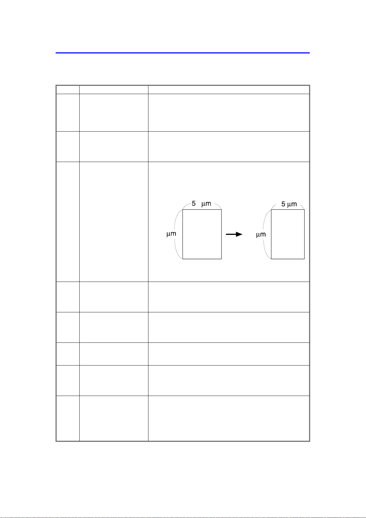
3 Thermal Head To minimize ink set-off, the shape of the thermal head
heating elements have been changed as shown below.
C225V500.img
4 Paper Table Side
Fences
5 Master Eject Box To prevent the used master from drooping when the
6 Paper Delivery Table The delivery end fence and the side fences can be folded
7 Master Eject Box
Capacity
8 Economy Mode If Economy mode is selected, the thermal head energy is
For easy side fence positioning, a rack and pinion
mechanism has been installed. The left and right side
fences move together.
customer takes out the master eject box, a master holder
has been added to the master eject box.
for storing in the delivery table.
The pressure for compacting the master in the master
eject box has been increased. The master eject box
capacity has been increased from 15 to 25 masters.
reduced by 15% (this is done by changing the pulse
width). The image density will be slightly lighter, and ink
consumption will be less than normal.
1-4
Page 8
5 September 1995 ESSENTIAL DIFFERENCES BETWEEN THE C217 AND THE C225
No. Item Remarks
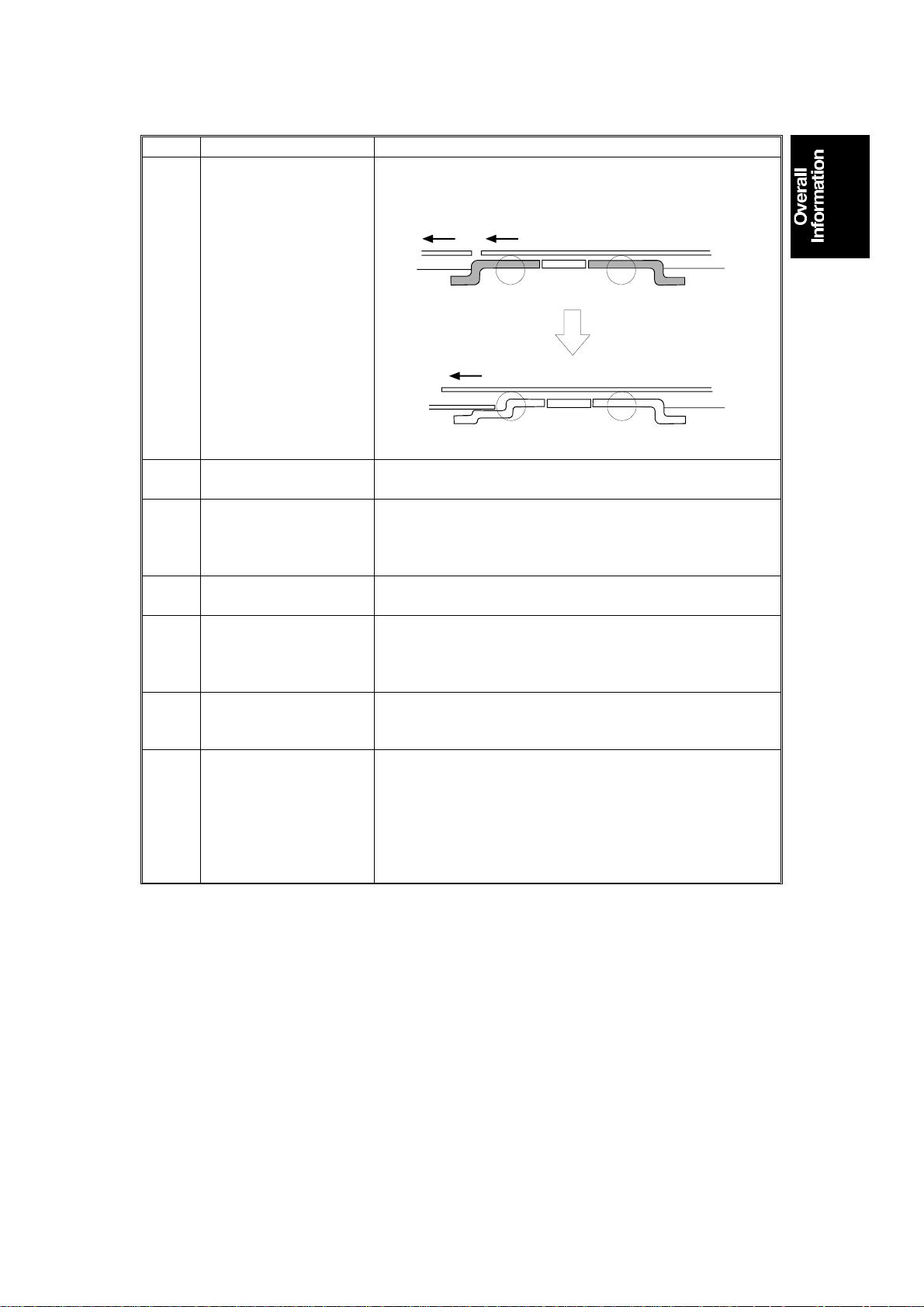
9 Exposure Glass Bracket To prevent the scanned original from being pushed out by
the next original, the shape of the exposure glass bracket
has been changed as shown below.
H225V501.wmf
10 Original Feed Spring
Plate
To ensure proper feeding of thin paper, the angle of the
original feed spring plate has been changed.
11 Paper Feed Timing To reduce noise which occurs when the paper hits the
2nd feed roller, the first paper feed length has been
reduced. (The buckle between the 1st and 2nd paper
feed rollers has been shortened.)
12 Skip Feed A user can select from 2 to 9 rotations of the drum while
one sheet of paper is fed.
13 A4 Size Drum (Only A4
machines)
To minimize master consumption, the screen mesh length
and the master cut length of the Europe/Asia machines
has been shortened. (The master consumption of the
LT/LG machines is the same as for the C217.)
14 Quality Start The first print tends to be light. To increase the image
density of the first print, Quality Start mode can be
selected. In this mode, the first print is made at 30 rpm.
15 Image Processing in
the "Darker 2" setting
In the C217 model, only the A/D conversion parameters
are changed when the image density setting is changed.
This does not change the density of solid black areas.
In the C225 model, if "Darker 2" is selected on the
operation panel, the thermal head energy is increased to
115% of the normal setting. The solid black areas will
become darker.
1-5
Page 9
PRINTING PROCESS 5 September 1995
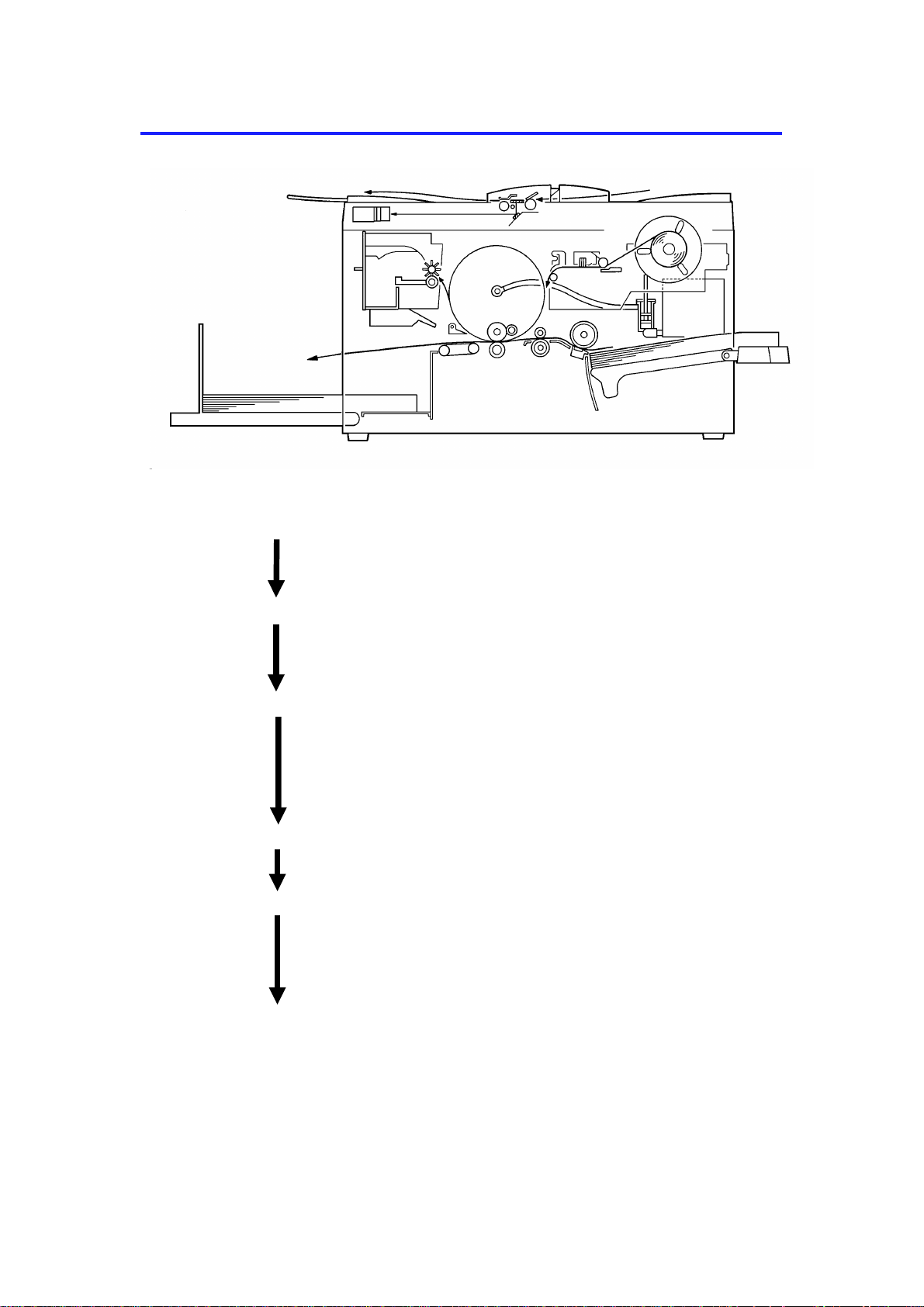
3. PRINTING PROCESS
2
1
3
5
6
4
C225V502.img
1. Master Ejecting: The machine ejects the used master
wrapped around the dru m into the master
eject box.
2. Scanning: The machine scans the original using the
CCD, through the mirror and the lens,
while feeding the original.
3. Master Feeding: The machine converts the signa l from th e
CCD into digital signals and sen ds th em to
the thermal head to ma ke holes in the
master. The master then wraps aro un d
the drum.
4. Paper Feeding: The machine sends paper separat ely to
the drum.
5. Printing: The ma chin e presses the paper fed from
the paper feed section against the drum.
This transfers the ink to the pap er through
the drum screen and the master.
6. Paper Delivering: The machine peels off the printed paper
with the exit pawls and air knife, and
ejects the paper onto th e pa pe r delivery
table.
1-6
Page 10
10
5 September 1995 MECHANICAL COMPONENT LAYOUT
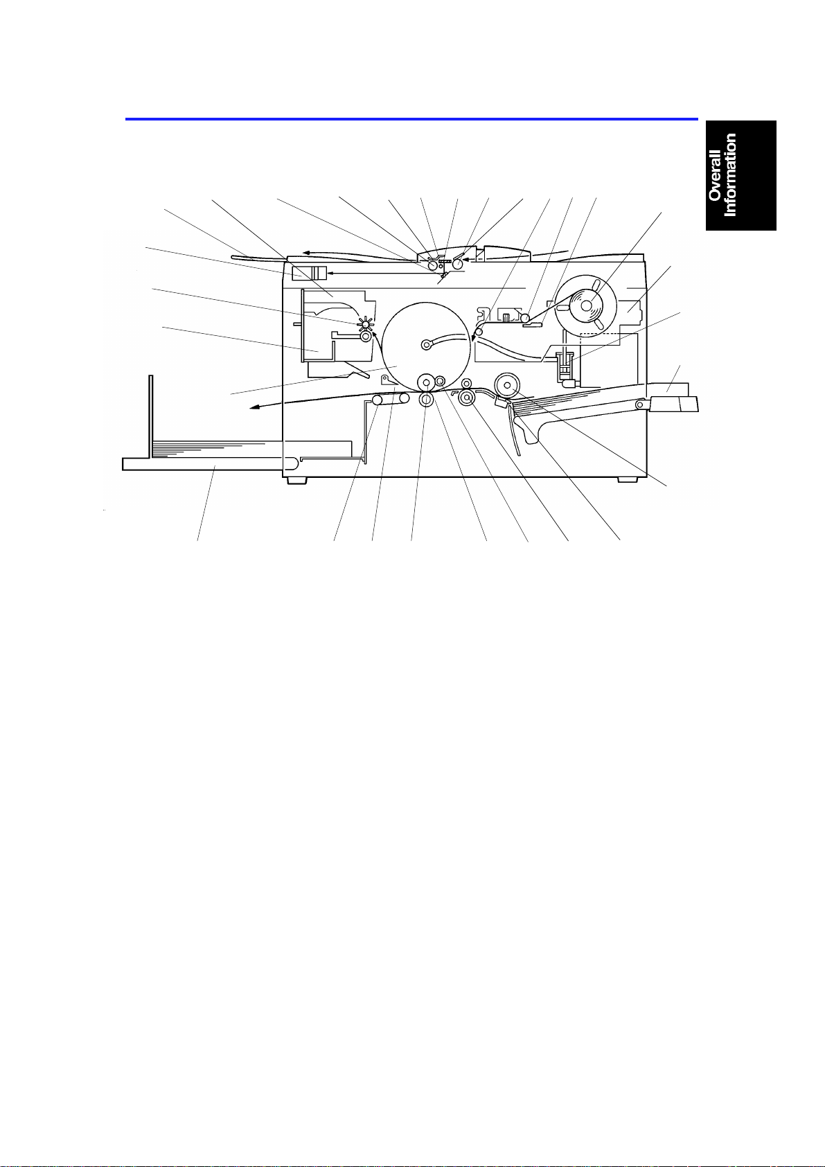
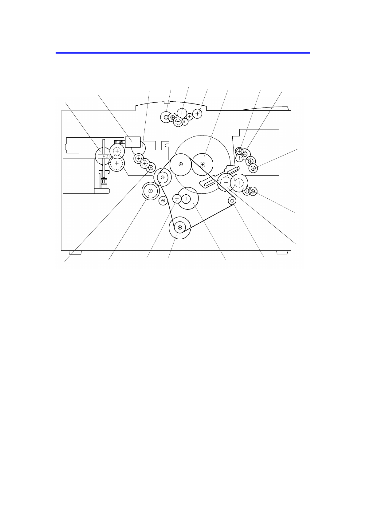
4. MECHANICAL COMPONENT LAYOUT
27
26
28
25
29
24
1234
5
6789
11
12
13
14
15
1617181920212223
1. Mirror
2. Original Feed Roller
3. Original Pressure Plate
4. Exposure Lamp
5. Exposure Glass
6. Original Pick-up Roller
7. Original Friction Pad
8. Master Tension Roller
9. Platen Roller
10. Thermal Head
11. Master Roll
12. Platter Unit
13. Ink Pump
14. Paper Table
15. Paper Feed Roller
C225V502-2.img
16. Friction Pad
17. 2nd Feed Roller
18. Doctor Roller
19. Press Roller
20. Ink Roller
21. Exit Pawl
22. Transport Unit
23. Paper Delivery Table
24. Drum
25. Master Eject Box
26. Master Eject Roller
27. CCD Unit
28. Original Exit Tray
29. Master Eject Unit
1-7
Page 11
14
DRIVE LAYOUT 5 September 1995
5. DRIVE LAYOUT
2
3
5
4
6
7
8
9
1
10
11
12
18
17
16
15
1. Pump Drive Gear
2. Ink Supply Motor
3. Platen Roller Gear
4. Original Feed Motor
5. Original Pick-up Roller
6. Original Feed Roller
7. Drum Drive Gear
8. Upper Master Eject Roller Gear
9. Lower Master Eject Roller Gear
13
C225V503.img
10. Master Eject Motor
11. Master Clamper Motor
12. Master Clamper Drive Gear
13. Transport Unit Drive Pulley
14. 2nd Feed M otor
15. Main Motor
16. 2nd Feed Roller Gear
17. Paper Feed Roller Gear
18. Master Feed Motor
1-8
Page 12
5 September 1995 ELECTRICAL COMPONENT DESCRIPTION
6. ELECTRICAL COMPONENT DESCRIPTION
Index No. Name Function
Motors
11 Master Feed Feeds the master to the drum.
25 Master Eject Sends the used master into the master eject
box.
28 Main Drives the paper feed, drum, printing and
paper delivery unit components.
29 Vacuum Provides suction so paper is held firmly on
the transport belt.
32 2nd Feed Drives the 2nd feed roller.
35 Master Clamper Open and closes the master clamper.
38 Air Knife Rotates the fan which generates the air knife
to separate the paper from the drum.
40 Pressure Plate Drives the pressure plate.
45 Original Feed Transports the original for scanning.
46 Master Cutter Cuts the master.
49 Ink Supply Drives the ink pump to supply ink.
Solenoid
31 Pressure Release
Solenoid
Sensors
1 Master End Detects if the plotter unit has run out of
3 Original Registration
(Upper: light receiver,
Lower: light emitter)
14 Feed Jam Timing Determines the paper misfeed check timing.
15 Paper End Detects if there is any paper on the paper
16 Registration Detects paper misfeeds.
17 Feed Start Timing Determines the paper feed start timing.
18 Exit Jam Timing Determines the master misfeed check timing.
19 Master Eject Position Detects the master eject position of the drum.
26 Drum Master Detects if there is a master on the drum.
30 Exit Detects paper misfeeds.
33 Master Eject Detects used master misfeeds.
37 Full Master Detects if the master eject box is full.
39 Pressure Plate H.P. Detects the pressure plate home position.
48 Original Set Detects if there is an original on the original
Switches
5 ADF Open Checks if the ADF is open.
6 Left Cutter Determines the left limit position of the cutter.
9 Master Cut Starts the cutter motor to cut the master.
13 Paper Table Set Detects if the paper table is in the paper feed
Releases the press roller to apply printing
pressure.
master roll.
Informs the CPU of the original position.
Also, detects original misfeed.
table.
table.
position.
1-9
Page 13

ELECTRICAL COMPONENT DESCRIPTION 5 September 1995
Index No. Name Function
21 Scanner Unit Open Checks if the scanner unit is open.
22 Delivery Cover Open Checks if the delivery cover is open.
23 Main Turns the power on or off.
27 Master Eject Box Checks if the master eject box is set
correctly.
36 Master Clamper Detects the master clamper open/close
position.
47 Right Cutter Determines the right limit position of the
cutter.
Printed Circuit Board
4 Lamp Control Controls the power to the exposure lamp.
8 Operation Panel Interfaces the CPU with the operator.
12 Main Controls all machine functions.
20 Power Supply Provides power for all dc components.
24 Main Motor Control Controls the main motor speed.
34 Noise Filter Filters out electrical noise on the ac power
input lines.
41 CCD Converts light intensity into an electrical
signal.
42 A/D Conversion Converts the analog signals into digital
signals.
Counters
7 Print Keeps track of the total number of prints
made.
10 Master Keeps track of the total number of masters
made.
Others
2 Thermal Head Makes the master using heat.
43 Paper Feed Clutch Transmits main motor drive to the paper feed
roller at the appropriate time.
44 Exposure Lamp Illuminates the original for exposure.
1-10
Page 14

SECTION 2
DETAILED SECTION
DESCRIPTIONS
Page 15
5 September 1995 PAPER FEED
1. PAPER FEED
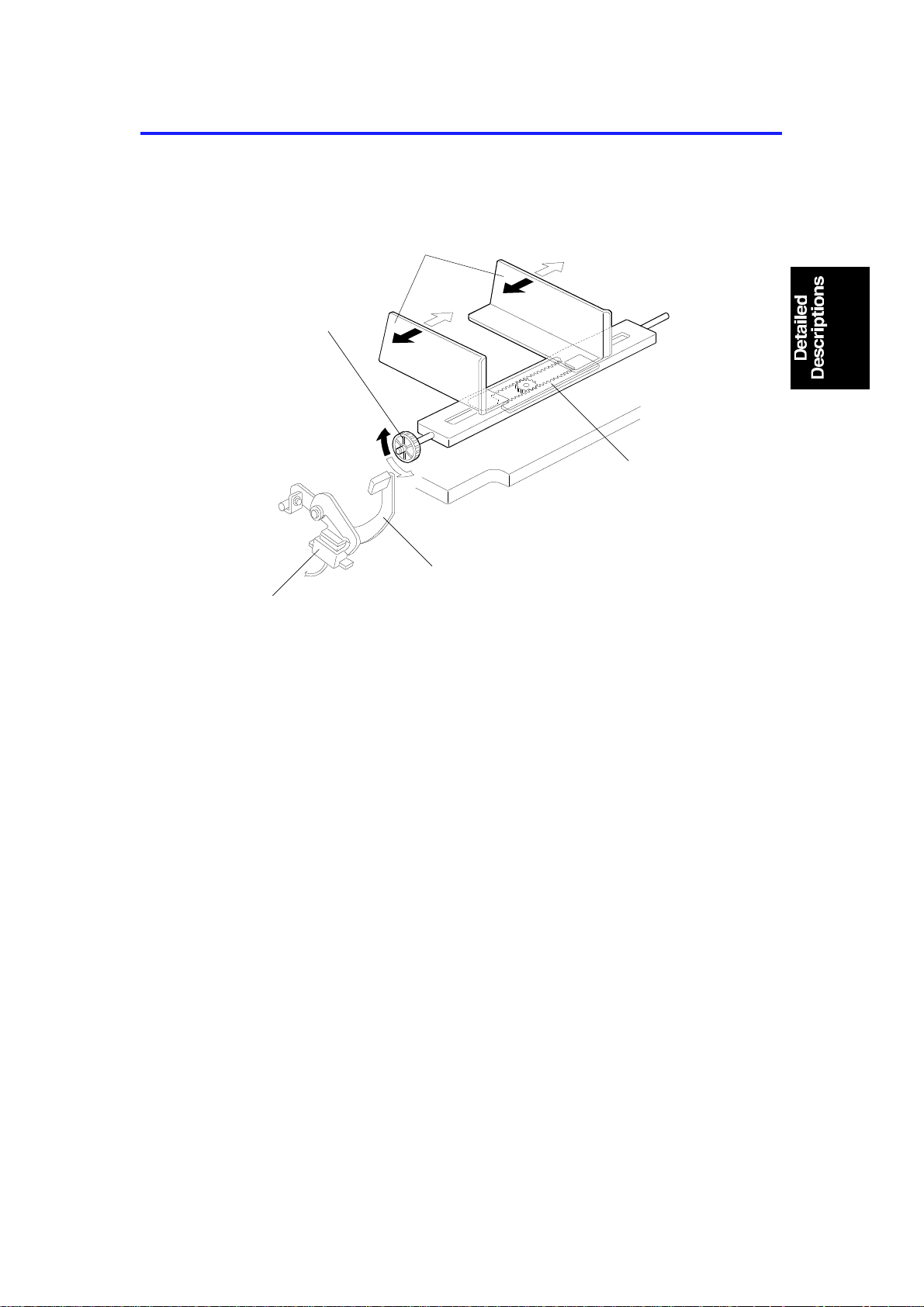
1.1 PAPER TABLE
[C]
[E]
[A]
[B]
[D]
C225D506.wmf
The paper table side fen ces [A ] should be adjusted depending on the pap er
size. The left and right side fences move together because of the rack a nd
pinion [B], to ensure correct pap er positioning on the tray. If the dial [C] is
turned, the side fen ces move together, changing the paper po sitio n on the
table.
When the lever [D] is lowered and the paper table is in the no-paper feed
position, the magnetic switch [E] is de-act ivat ed . In this con dit ion, the Print
Start key is disabled.
2-1
Page 16

[C]
PAPER DELIVERY SECTION 5 September 1995
2. PAPER DELIVERY SECTION
2.1 OVERALL
[B]
[A]
[D]
C225D505.img
The exit pawl [A] and the air knife [B] sep ara te the paper fro m t he drum. Th e
paper is transported to the delivery table by the transport unit [C].
There is a reflective photosensor [D] to detect paper jams.
2-2
Page 17

[A]
[D]
5 September 1995 PAPER DELIVERY SECTION
2.2 VACUUM UNIT DRIVE MECHANISM
[B]
[C]
C225D507.wmf
The vacuum fan [A] holds the paper against the transport be lts [B ] to deliver
the paper to the delivery t ab le. The transport belts are driven by the main
motor through gears [C] .
The exit sensor (reflective photo sen sor) [D] located on the vacuum unit
detects paper jams.
2-3
Page 18

IMAGE PROCESSING 5 September 1995
3. IMAGE PROCESSING
3.1 IMAGE DENSITY SETTING
The A/D conversion paramet ers (refer to page 2-43 of the C217 model
service manual) and thermal head energy change depending on the image
density selected on the operat ion panel.
The table below shows th e relationships between the image mode s,
parameters, and the thermal head energy.
VH (%) M1 (%) M2 (%) M3 (%) VL (%) T/H
Energy
(%)
Shading Distortion Memory 100 86.5 73.0 59.5 46.0
Image
Setting
Line Mode Lighter 74.0 57.0 40.0 23.0 6.0 100
Normal 100 76.5 53.0 29.5 6.0 100
Darker 1 100 79.8 59.5 39.3 19.0 100
Darker 2 100 79.8 59.5 39.3 19.0 115
Photo
Mode
Lighter 70.0 36.6 19.6 11.4 7.0 100
Normal 80.0 43.4 24.8 15.8 11.0 100
Darker 1 85.0 47.9 29.0 19.9 15.0 100
Darker 2 85.0 47.9 29.0 19.9 15.0 115
In the C217 model, the the rmal head energy is always the same regardless
of the image density setting. Only the A/D conversion parame te rs ch an ge
depending on the selected image density. Using this method , the imag e
density of solid black areas does not change even if a darker setting is
selected. This is because all the pixel data will be the same (evenly black)
after the binary processing, if the area is purely bla ck.
In the C225 model, when Darker 2 is selected , th e A/ D conve rsion
parameters are the same as those of Darker 1, but the thermal hea d energy
increases to 115% of the norma l the rmal head energy. (Th is is done by
changing the pulse width.) As a result, the densit y of solid black are as will
become darker.
2-4
Page 19

5 September 1995 MASTER PLOTTING AND PRINTING AREA
4. MASTER PLOTTING AND PRINTING AREA
1. Length (Legal Drum)
Original
Master
Screen
Paper
(Shift : 0 mm)
Paper
(Shift : 15 mm)
Paper
(Shift : –15 mm)
2-5
C225D502.wmf
Page 20

Original
Screen
MASTER PLOTTING AND PRINTING AREA 5 September 1995
(A4 Drum)
Master
Paper
(Shift : 0 mm)
Paper
(Shift : 15 mm)
Paper
(Shift : –15 mm)
C225D503.wmf
2-6
Page 21

5 September 1995 MASTER PLOTTING AND PRINTING AREA
2. Width (Legal and A4 Drum)
Original
Master
Screen
Paper
C225D504.wmf
2-7
Page 22

TIMING CHART 3 (Master Cut/Trial Print) is identical to that of C217 model.
TIMING CHART 5 September 1995
5. TIMING CHART
5.1 MASTER EJECT (TIMI NG CHART 1)
2-8
C225D500.wmf
Page 23

5 September 1995 TIMING CHART
5.2 ORIGINAL FEED/PLOTTING (TIMING CHART 2)
2-9
C225D501.wmf
Page 24

SECTION 3
INSTALLATION
Page 25

5 September 1995 INSTALLATION REQUIREMENTS
1. INSTALLATION REQUIREMENTS
The installation loca tion should be carefully chosen becau se the
environmental con dit ions greatly affect the performan ce of the machine.
1.1 OPTIMUM ENVIRONMENTAL CONDITIONS
C225I500.img
Temperature — 10 to 30°C
(50 to 86°F)
Humidity — 20 to 90 % RH
C225I501.img
On a strong and level base.
The machine must be level within
5 mm (13/64") both front to rear
and left to right.
3-1
Page 26

INSTALLATION REQUIREMENTS 5 September 1995
1.2 ENVIRONMENTS TO AVOID
C225I502.img
Locations exposed to direct
Dusty areas.
C225I503.img
sunlight or strong light (more than
1,500 lux).
C225I504.img
C225I505.img
Areas with corrosive gases. Locations directly expo sed to cool air
from an air conditioner or reflected
heat from a space heater. (Sudden
temperature changes from low to
high or vice versa may cause
condensation within the machine.)
3-2
Page 27

5 September 1995 INSTALLATION REQUIREMENTS
1.3 POWER CONNECTION
C225I506.img
Securely connect the power cord
to a power source.
Make sure that the wall outlet is
near the machine and easily
accessible.
Make sure the plug is firmly
inserted in the outlet.
C225I507.img
Voltage must not fluctuate more
than 10%.
C225I508.img
C225I509.img
Avoid multiwiring. Do not pinch the power cord.
3-3
Page 28

More than
(24.0")
(27.6")
INSTALLATION REQUIREMENTS 5 September 1995
1.4 ACCESS TO THE MACHINE
Place the machine near a power sou rce, provid ing cle ara nce as shown belo w.
10 cm (4.0")
Paper
Delivery
Table
More than
60 cm
(23.7")
105 cm (41.3")
Paper
Feed
Table
More than
60 cm
(23.7")
61 cm
70 cm
C225I510.wmf
3-4
Page 29

5 September 1995 INSTALLATION PROCEDURE
2. INSTALLATION PROCEDURE
1. Make sure that you have all the accessories listed below.
(1) Master Spool............ .. .. .. .. .. .. .... .. .. .. .. .. .. .... .. .. .. .2
(2) Paper Feed Side Pad...................................... 2
(3) Operating Instructions - English............... .. .... .1
(4) NECR (Ricoh version only) ........................ ..... 1
(5) Brand Stickers
(OEM version only).......................................... 1 set
(6) Model Name Plates
(OEM version only).......................................... 1 set
3-5
Page 30

INSTALLATION PROCEDURE 5 September 1995
[A]
C225I511.wmf
2. Mount the machine on a strong and level base.
NOTE: Use a sturdy desk, or someth ing similar. The machine must be
level within 5 mm (0.2") both front to rea r and left to righ t.
3. Remove the tape and string securing the covers and units as shown
above.
4. Open the paper feed tray. Then remove the cush ions [A] supporting the
paper feed table and scan ne r co ver.
5. Firmly insert the plug in the wall outlet.
NOTE: Make sure that the wall o ut let is near th e machine and easily
accessible.
6. Turn on the main switch.
3-6
Page 31

5 September 1995 INSTALLATION PROCEDURE
7. Load paper as follows:
a. Open the paper feed table.
b. Press down the feed roller
pressure lever.
C225I512.img
c. Place the paper on the
paper feed table.
d. Adjust the paper feed side
plates to match the paper size.
e. Lift the feed roller pressure
lever.
f. Make sure that the paper
feed side plates contact the
paper lightly.
C225I513.img
C225I514.img
3-7
Page 32

INSTALLATION PROCEDURE 5 September 1995
8. Open the paper delivery table.
9. Move the paper delivery end
and side plates to mat ch the
print paper size.
C225I516.img
10. Install the master roll as follows:
a. Insert both spools int o th e
new master roll.
b. Open the top cover.
c. Position the master roll.
d. Lift the pressure re lea se
lever to release the platen
roller pressure.
C225I517.img
C225I518.img
3-8
Page 33

5 September 1995 INSTALLATION PROCEDURE
e. Insert the leading edge of
the master roll under the
platen roller. Then rotate the
master roll clockwise a little.
f. Return the pressure release
lever to its original position.
g. Turn on the main switch.
C225I519.img
h. Press the master cut button to cut
the leading edge of th e master
roll.
i. Remove the cut-off portion of the
master roll.
j. Close the top cover.
C225I520.img
C225I521.img
3-9
Page 34

INSTALLATION PROCEDURE 5 September 1995
11. Install the ink cartridge as follows:
a. Open the ink cover.
b. Press down the release
lever (green tab [A]).
Then pull out the ink
cartridge holder.
c. Open the ink cap and insta ll the
ink cartridge as shown in the
illustration.
C225I522.img
d. Slide in the ink cartridge holder.
Then press the setting lever
(green tab) until it clicks in
position.
e. Close the ink cover.
12. Make some test prints as follows:
a. Adjust the original guides to
match the original size.
b. Place an original face down.
c. Input the desired number of
prints with the number keys
and press the Master Making
key.
d. After one sheet of paper is
delivered, press the Print Start
key to make prints at the lowest
print speed until the print image
density stabilizes. Use a test
chart to check for changes in the
image density.
C225I523.img
e. Check the copy image after the
image is stabilized.
C225I524.img
3-10
Page 35

5 September 1995 INSTALLATION PROCEDURE
30 mm
18
mm
BRAND DECAL AND NAME PLATE INSTRUCTIONS
This procedure is for the OEM version machines only.
1. Peel off the backing film of the brand decal (accessory).
2. Adhere the brand decal to the operation pan el as sho wn.
3. Peel off the backing film of the model name plate (accessory).
4. Adhere the model name plate in the recess on th e fro nt cover.
3-11
C225I525.img
Page 36

SECTION 4
SERVICE TABLES
Page 37

5 September 1995 MAINTENANCE TABLE
1. MAINTENANCE TABLE
The following items should be maint ained periodically. There are two sets of
intervals - one based on time and the other base d on print coun t. For
maintenance items with entrie s in both of them , use whiche ver comes first.
C: Clean R: Replace L: Lubricate A: Adjust
Interval
Item
Scanner/Optics
Exposure Lamp C C C Dry Cloth
Original Pick-up Roller R
Mirror/Reflector C C C Soft Cloth
Exposure Glass C C C Dry Cloth
Original Registration
Sensor
Original Friction Pad R R R
Master Feed
Platen Roller
Master Eject Rollers C C C Alcohol
Drum Master Sensor C Dry Cloth
Paper Feed
Paper Feed Roller R R R R R R R R R
Friction Pad C C C C R R Damp Cloth
Press Roller R R
Paper Feed Roller
One-way Clutch
Paper Feed Clutch R
Feed Roller Bushing
Feed Roller Drive Gears
Registration/Exit Sensors C C C C Dry Cloth
2nd Feed Roller C C C C Dry Cloth
Transport Unit Drive Gear
Bearing
Transport Unit Gears
Drum and Ink Supply
Cloth Screen R R
Drum Drive Gears and
Cam
Drum Flange Bushing
Inside/Outside of the
Drum
Ink Pump Nozzle C C C Alcohol
Time Print Counter
6M 1Y 2Y 3Y 300K 600K 1M 1.2M 2M
CCC
RRR
RR
LLL
LLL
LLL
LLL
LLL
LLL
CCC
EM NOTE
Dry Cloth
Expected life
is 6K masters.
Motor Oil
(SAE #20)
Grease
(Albania #2)
Motor Oil (SAE
#20)
Grease
(Albania #2)
Grease
(Albania #2)
Motor Oil
(SAE #20)
Alcohol
4-1
Page 38

MAINTENANCE TABLE 5 September 1995
Interval
Item
Others
Timing Belt Tension A
Press Roller Lock Lever
Position
Time Print Counter
6M 1Y 2Y 3Y 300K 600K 1M 1.2M 2M
EM NOTE
A
4-2
Page 39

5 September 1995 LUBRICATION POINTS
2. LUBRICATION POINTS
2.1 FEED ROLLER BUSHING
Lubricant: Motor Oil
C225M500.img
4-3
Page 40

LUBRICATION POINTS 5 September 1995
2.2 TRANSPORT UNIT DRIVE GEAR BEARING
Lubricant: Motor Oil
C225M504.wmf
2.3 TRANSPORT UNIT GEARS
Lubricant: Grease (Alban ia #2 )
C225M505.wmf
4-4
Page 41

5 September 1995 LUBRICATION POINTS
2.4 FEED ROLLER DRIVE GEARS
Lubricant: Grease (Alban ia #2 )
C225M501.img
2.5 DRUM DRIVE GEARS AND CAM
Lubricant: Grease (Alban ia #2 )
C225M502.img
4-5
Page 42

LUBRICATION POINTS 5 September 1995
2.6 DRUM FLANGE BUSHING
Lubricant: Motor Oil
C225M503.img
4-6
Page 43

5 September 1995 SPECIAL OPERATION MODES
3. SPECIAL OPERATION MODES
3.1 SKIP FEED MODE
Customers can select the number of rota tions of the drum for one print by the
following key operation.
• While pressing the Clear key and Stop key, select the numb er of rotations
of the drum while one sheet of paper is fed using the Number keys (1 to 9
can be selected.).
To cancel the skip feed mode, follow one of the procedures belo w.
• While pressing the Clear key and Stop key, select 1 using the Nu mbe r
key.
• While pressing the Reset key, press the Clea r ke y.
• Turn the main switch off and on.
3.2 ECONOMY MODE
Customers can select this mod e by the following key operation. If th is mo de
is selected, the thermal head energy (pulse width) is reduced by 15%. The
image will be lighter and ink consumption will be reduced.
• While pressing the Clear key and Image Den sity key, press th e Image
Mode key.
To cancel the economy mod e, follo w o ne of the procedures below.
• While pressing the Reset key, press the Clea r ke y.
• Turn the main switch off and on.
3.3 QUALITY START MODE
This mode increases the image de nsit y of th e 1st print. Normally, the first
print after the proof print is made at the selected copy speed (70, 100 or
130 rpm). If the Quality Start mo de is selected by the following key operation,
the 1st print is made at 30 rpm.
• While pressing the Clear key, press the < and > keys.
To cancel the quality start mode, follo w one of the pro cedures below.
• While pressing the Reset key, press the Clea r ke y.
• Turn the main switch off and on.
4-7
Page 44

INPUT/OUTPUT CHECK MODE 5 September 1995
4. INPUT/OUTPUT CHECK MODE
The electrical component s can be checke d with this program. The input
check mode can check if the sensors or switch es function correctly. The
output check mode can manually activa te the elect rical devices, such as
motors and solenoids.
4.1 ACCESS PROCEDURE
1. Turn on the main switch while holding down the Print Start, Stop, and
Clear keys at the same time.
2. The memory indicator displays "01", which indicates th at the Inp ut Check
mode is selected.
3. To select the Output Check mode, press the Memory/Class key. The
memory indicator displays "00".
4.2 DRUM FREE RUN MODE
1. Select either the Input or Output Check mode.
2. Select the Photo mode by pressing the Im ag e Mode key.
3. To start the free run, press the Image Density key. Operation depends on
the Image Density selectio n as fo llows:
Image Density Selection Drum Speed
Lighter 30 rpm
Normal Stop
Darker 30 rpm
Darkest 70/100/130 rpm (see Note)
NOTE: The drum speed can be change d with the Spe ed key.
4-8
Page 45

5 September 1995 INPUT/OUTPUT CHECK MODE
4.3 INPUT CHECK MODE
By entering a number list ed belo w aft er accessing the input check mode, the
input level from each electrical device can be checked. Depending on th e
electrical device’s condition , th e be eper sounds and the machine status
indicators light.
No. Device Conditions when the beeper sounds
1 Feed Start Timing Sensor The sensor is actuated
2 Feed Jam Timing Sensor The sensor is actuated
3 Exit Jam Timing Sensor The sensor is actuated
Master Eject Position
4
Sensor
5 Drum Master Sensor The sensor detects a master on the drum
6 Cover Safety The scanner unit is open
7 Master End Sensor The sensor detects no master
8 Master Cut Switch The switch is pressed
9 Right Cutter Switch The switch is actuated
10 Left Cutter Switch The switch is actuated
11 Paper End Sensor The sensor detects no paper
12 Registration Sensor The sensor detects paper
13 Exit Sensor The sensor detects paper
Master Clamper Switch
14
(Open)
Master Clamper Switch
15
(Close)
16 Original Set Sensor The sensor detects an original
Original Registration
17
Sensor
18 ADF Open Switch The ADF is closed
19 Master Eject Sensor The sensor is actuated
20 Pressure Plate H.P. Sensor The sensor is actuated
21 Full Master Sensor The sensor is actuated
22 Paper Table Set Switch The switch is on
23 DIP SW 103-1 The switch is on
24 DIP SW 103-2 The switch is on
25 DIP SW 103-3 The switch is on
26 DIP SW 103-4 The switch is on
27 DIP SW 103-5 The switch is on
28 DIP SW 103-6 The switch is on
29 DIP SW 103-7 The switch is on
30 DIP SW 103-8 The switch is on
The sensor is actuated
The clamper is open
The clamper is closed
The sensor detects an original
4-9
Page 46

INPUT/OUTPUT CHECK MODE 5 September 1995
4.4 OUTPUT CHECK MODE
You can turn on each electrical device listed below individually. The
procedure is as follows:
1. Select the output check mode.
2. Enter the number of the device which you would like to turn on.
3. Press the Print key to turn on the device.
4. To turn off the device, press the Clear key.
NOTE: Some of these are devices are turned on only while the Print key
is pressed (marked with *).
CAUTION:
I
1. Do not turn the drum manually nor by using the output mode when
the clamper is opened with the output mode.
2. Do not open the clamper when the drum is not at the master fee d
or eject positions. Use the drum stop functions (No. 15 or 16)
before opening the clamper.
No. Device/Function Note
Thermal Head Power is applied to the thermal head for 30 seconds
1
2 Paper Feed Clutch *
3 Pressure Release Solenoid *
4 Master Eject Motor *
5 Ink Supply Motor *
Master Cutter Motor The motor stops when one of the cutter time
6
Print Counter The counter is increased by one each time the Print
7
Master Counter The counter is increased by one each time the Print
8
9 Exposure Lamp
Master Clamper Motor (Open) * The motor stops when the master clamper switch
10
Master Clamper Motor (Close) * The motor stops when the master clamper switch
11
12 Master Feed Motor
13 Original Feed Motor
14 Shading Distortion Correction The shading distortion memory is rewritten.
Drum Stop (Master Exit) The drum turns and stops at the master eject
15
Drum Stop (Master Feed) The drum turns and stops at the master feed
16
after the Print key is pressed. While the power is
applied to the thermal head, the beeper sounds.
sensors is activated.
key is pressed.
key is pressed.
detects the clamper open condition.
detects the clamper closed condition.
position automatically.
position automatically.
4-10
Page 47

5 September 1995 INPUT/OUTPUT CHECK MODE
No. Device/Function Note
Pressure Plate Motor *
17
(To Home Position)
Pressure Plate Motor *
18
(To the Compression Position)
19 Air Knife Motor *
20 Vacuum Motor
21 Operation Panel Indicators Turns on all the indicators on the operation panel.
The motor moves pressure plate towards to the
home position. The motor stops when the pressure
plate H.P. sensor is actuated.
The motor moves the pressure plate towards to the
master compression position. The motor stops
when the full master box sensor is actuated.
4-11
Page 48

SERVICE TABLES 5 September 1995
5. SERVICE TABLES
5.1 TEST POINT TABLE
Main PCB
No Usage
TP101
TP102
TP103
TP104
TP105
TP106
TP107
TP108
TP109
TP110
TP111
A/D Conversion PCB
–12 V
Ink Level (Standard Pulse)
Ink Level (Detection Pulse)
GND–b
+12 V
+24 V
4MHz Clock
+38 V
+5 V
GND–a
Original Registration Sensor
No Usage
TP201
TP202
TP203
TP204
OS Signal (CCD Output)
VS Signal (Inverted and Amplified CCD Output)
GND
Scan Line Trigger
5.2 VARIABLE RESISTOR TABLE
Main PCB
No Usage
VR101
VR102
A/D Conversion PCB
No Usage
VR201 White Level Adjustment
Power Supply PCB
No Usage
VR301
VR401
Ink Detection Adjustment
Original Registration Sensor Adjustment
Factory Use Only (+5V Adjustment)
Thermal Head Voltage Adjustment
4-12
Page 49

5 September 1995 SERVICE TABLES
5.3 DIP SWITCH TABLE
Main PCB
DPS 101 OFF ON
1 Outputs a Test Pattern 2 Dither Matrix (Screw Pattern) 3 Dither Matrix (Bayer Pattern) 4 Dither Matrix (8 x 8 Pattern) 5 Dither Matrix (6 x 6 Pattern) Dither Matrix (4 x 4 Pattern)
6 Normal Edge Emphasis in Photo Mode
7 Normal Enable Data Noise Filter
8 Production Use Only Must be ON
Factory Setting
DPS 101
1ON
2ON
3ON
4ON
DPS 101
5ON
6OFF
7OFF
8ON
If two or more of DPS 101-2 ∼ 6 are OFF, the image will not be produced.
DPS 102
1 Not Used
DPS 102
2 3 4 Leading Edge Registration Adjustment
OFF
OFF
OFF
OFF
ON
ON
ON
ON
OFF
OFF
ON
ON
ON
ON
OFF
OFF
OFF
ON
OFF
ON
ON
OFF
ON
OFF
+2.4 mm
+1.6
+0.8
0 (Standard)
–0.8
–1.6
–2.4
–3.2
4-13
Page 50

SERVICE TABLES 5 September 1995
DPS 103
1 2 3 Vertical Magnification
OFF
OFF
OFF
OFF
ON
ON
ON
ON
DPS103 Description
45Trailing Edge Erase Margin Adjustment
OFF
OFF
ON
ON
DPS 103 OFF ON
6
7
8
OFF
OFF
ON
ON
OFF
OFF
ON
ON
OFF
ON
OFF
ON
Normal
LG version
Normal
OFF
ON
OFF
ON
OFF
ON
OFF
ON
+1mm
+2 mm
+3 mm
–1mm
+1.75%
+1.25
+0.75
0 (Standard)
–0.75
–1.25
–1.75
–2.25
Enable Key Counter Operation
A4 version
Print and master counters do not change.
5.4 LED TABLE
Main PCB
LED # OFF ON
101
102
Insufficient Ink
–
Sufficient Ink
During Paper Feed
5.5 FUSE TABLE
Main PCB
FUSE #
101 630 mA 24 V
102 4 A 38 V Air Knife Motor
Rated
Current
Voltage Device
Master Cutter, Master Clamper, and Pressure Plate
Motors
Protect
4-14
 Loading...