

Ricoh SR3170, SR3160 Field Service Manual

Booklet Finisher SR3170 /
Finisher SR3160
Machine Code: D688/D689
Field Service Manual
July, 2014
Subject to change


Revision Lists
Version Section Details
1.00 Initial release of this document
1.10
Replacement and Adjustment
Section Item Note
Exterior Cover
Boards
Main Unit (Motor) Corner Stapling Unit
Main Unit (Sensor) Staple Tray Paper Sensor
Read This First > Safety and
Symbols
Front Cover, Front Left Side
Cover
End Fence (D688 Only)
Main Board > When replacing
the main board
Changed some icons.
Step before step 1 is deleted.
Number of hooks in step 3 is revised.
Picture “d689z0001” in step 3 is
replaced.
Step 5 and 6 are added.
E-ring in step 5 is changed from clip.
E-ring in step 8 is changed from clip.
Picture “d1351295” in step 3 is
replaced.
Booklet unit Step 7 is added.
Booklet Unit
Press Folding Motor E-ring in step 2 is changed from clip.
Punch Unit -
Step 2 is revised.
Picture “d146z0063” in step 2 is
replaced.
Step 3 is revised.
Picture “d146z0064” in step 3 is
replaced.
1
Safety and Symbols
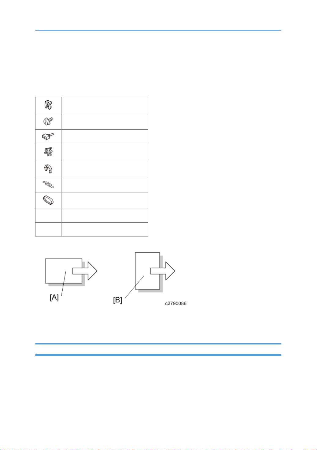
This manual uses several symbols and abbreviations. The meaning of those symbols and abbreviations
are as follows:
Clip ring
Screw
Connector
Clamp
E-ring
Spring
Timing belt
SEF Short Edge Feed
LEF Long Edge Feed
[A] Short Edge Feed (SEF)
[B] Long Edge Feed (LEF)
Trademarks
Microsoft®, Windows®, and MS-DOS® are registered trademarks of Microsoft Corporation in the
United States and /or other countries.
PostScript® is a registered trademark of Adobe Systems, Incorporated.
PCL® is a registered trademark of Hewlett-Packard Company.
Ethernet® is a registered trademark of Xerox Corporation.
2

PowerPC® is a registered trademark of International Business Machines Corporation.
Other product names used herein are for identification purposes only and may be trademarks of their
respective companies. We disclaim any and all rights involved with those marks.
The Aim of Anti-tip Components and Precautions
The anti-tip components are necessary for meeting the requirements of IEC60950-1, the international
standard for safety.
The aim of these components is to prevent the products, which are heavy in weight, from toppling as a
result of people running into or leaning onto the products, which can lead to serious accidents such as
persons becoming trapped under the product. (U.S.: UL60950-1, Europe: EN60950-1)
Therefore, removal of such components must always be with the consent of the customer.
Do not remove them at your own judgment.
3

TABLE OF CONTENTS
Revision Lists........................................................................................................................................................1
Safety and Symbols............................................................................................................................................2
Trademarks.....................................................................................................................................................2
The Aim of Anti-tip Components and Precautions.......................................................................................3
1. Replacement and Adjustment
Exterior Covers....................................................................................................................................................7
Rear Upper Cover, Rear Lower Cover, Upper Cover, Upper Right Cover...............................................7
Front Cover, Front Left Side Cover, Front Inner Cover................................................................................9
Paper Exit Cover..........................................................................................................................................11
Lower Tray....................................................................................................................................................12
Proof Tray.....................................................................................................................................................12
Upper Tray...................................................................................................................................................13
End Fence (D688 Only)..............................................................................................................................13
Left Cover (D689 Only)..............................................................................................................................16
Boards...............................................................................................................................................................19
Main Board..................................................................................................................................................19
When replacing the main board.......................................................................................................19
Corner Stapling Unit........................................................................................................................................21
Corner Stapling Unit....................................................................................................................................21
Stacking Roller Motor..................................................................................................................................25
Stacking Roller HP Sensor...........................................................................................................................26
Leading Edge Guide Motor........................................................................................................................28
Leading Edge Guide HP Sensor.................................................................................................................28
Trailing Edge Pressure Plate Motor............................................................................................................29
Trailing Edge Pressure Plate HP Sensor.....................................................................................................30
Shift Tray Paper Sensor...............................................................................................................................31
Feed Out Motor...........................................................................................................................................33
Feed Out Guide HP Sensor.........................................................................................................................33
Jogger Motor...............................................................................................................................................34
Jogger HP Sensor.........................................................................................................................................35
Shift Tray Exit Sensor...................................................................................................................................36
Staple Tray Paper Sensor............................................................................................................................37
Main Unit..........................................................................................................................................................39
4

Tray Exit Motor.............................................................................................................................................39
Middle Transport Motor..............................................................................................................................39
Pre-stack Transport Motor...........................................................................................................................40
Entrance Transport Motor...........................................................................................................................40
Horizontal Transport Motor........................................................................................................................41
Tray Lift Motor..............................................................................................................................................42
Lower Junction Gate Motor........................................................................................................................44
Shift Motor / Lower Junction Gate HP Sensor / Shift Roller HP Sensor.................................................45
Paper Exit Gate Motor................................................................................................................................47
Paper Exit Gate HP Sensor.........................................................................................................................50
Corner Stapling Paper Sensors...................................................................................................................
Proof Tray Full Sensor..................................................................................................................................52
Proof Tray Exit Sensor..................................................................................................................................52
Positioning Roller Motor / Feed Out Guide HP Sensor...........................................................................53
Entrance Sensor...........................................................................................................................................54
Horizontal Transport Sensor.......................................................................................................................55
Switchback Transport Sensor / Paper Transport Sensor..........................................................................57
Shift Tray Lower Limit Sensors.....................................................................................................................58
Booklet Paper Full Sensor 1, Booklet Paper Full Sensor 2 (D688 Only)................................................58
Booklet Unit (D688 Only)...............................................................................................................................60
Booklet Unit..................................................................................................................................................60
Press Folding Motor.....................................................................................................................................63
Booklet Jogger Motor..................................................................................................................................67
Booklet Guide Motor...................................................................................................................................67
Movement Roller Transport Motor.............................................................................................................68
Booklet Fence Motor...................................................................................................................................69
Folding Transport Motor.............................................................................................................................69
50
Booklet Stapler Motor Unit.........................................................................................................................70
Tray Upper Limit Switch...............................................................................................................................71
Folding Blade Cam HP Sensor...................................................................................................................76
Bottom Paper Exit Sensor............................................................................................................................78
Booklet Paper Sensor (Upper)....................................................................................................................80
Booklet Paper Sensor (Lower)....................................................................................................................81
5

Booklet Adjustment HP Sensor....................................................................................................................82
Booklet Jogger HP Sensor...........................................................................................................................82
Booklet Guide Sensor..................................................................................................................................83
Booklet Bottom Fence HP Sensor...............................................................................................................84
Punch Unit.........................................................................................................................................................86
Adjustment of the Flat Fold Booklet Unit.........................................................................................................88
Adjusting the Alignment of the Flat Fold Rollers........................................................................................88
Adjusting the Folding Speed.......................................................................................................................90
Stapler Unit.......................................................................................................................................................92
Stapler Movement Motor............................................................................................................................93
Stapler Movement HP Sensor.....................................................................................................................93
6

1. Replacement and Adjustment
Exterior Covers
Rear Upper Cover, Rear Lower Cover, Upper Cover, Upper Right Cover
1. Rear upper cover [A] ( ×2)
2. Rear lower cover [A] ( ×2)
7

1. Replacement and Adjustment
3. Open the front door [A], and remove the screws secured on the front side of the upper
cover [B] ( ×2)
4. Remove the screws secured on the rear side of the upper cover [A] ( ×2, hook×2)
• Check the positions of the bosses and hooks before removing the upper cover.
8

5. Upper right cover [A] ( ×2)
Exterior Covers
Front Cover, Front Left Side Cover, Front Inner Cover
1. Open the front cover [A].
2. Release the shaft bracket [B] ( upper direction) ( ×1).
9

1. Replacement and Adjustment
3. Front cover [A].
4. Front left side cover [A] ( ×2)
10
5. D688 only: Slightly pull out the booklet unit [A]
6. Front inner cover [B] ( ×1, ×2)
• Note that there is a LED connector inside the front inner cover. Be careful when removing the
front inner cover.

Paper Exit Cover
1. Paper exit cover [A] (hook×4)
Exterior Covers
• Check the positions of the bosses and hooks before removing the paper exit cover.
11

1. Replacement and Adjustment
Lower Tray
1. Lower tray [A]
12
Proof Tray
1. Remove the following covers (page 7)
•
Rear upper cover
• Upper cover

2. Proof tray [A] ( ×2)
Upper Tray
1. Upper tray [A] ( ×1)
Exterior Covers
End Fence (D688 Only)
1. Remove the following covers.
•
Front cover (page 9)
• Front left side cover (page 9)
• Rear upper cover (page 7)
13

1. Replacement and Adjustment
2. Upper tray [A] ( ×1)
3. Proof lower cover [A] (hook × 5)
14
4. Left upper cover [A]( ×2)

5. Mold bracket (front, rear) [A] ( ×2)
6. Shift tray bracket (front, rear) [A] ( ×4)
Exterior Covers
7. Shift tray bracket [A].
15

1. Replacement and Adjustment
8. End fence [A] ( ×2)
Left Cover (D689 Only)
1. Upper tray [A] ( ×1)
16

2. Rear mold bracket [A] ( ×1)
3. Front mold bracket [A] ( ×1)
Exterior Covers
4. Shift tray bracket [A] ( ×4)
17

1. Replacement and Adjustment
5. Left cover [A] ( ×3)
18

Boards
Main Board
1. Remove the following covers.
Rear upper cover (page 7)
•
• Rear lower cover (page 7)
Boards
2. Main board [A] (
×8, ×all)
When replacing the main board
This board has two blocks of dip switches. When you reinstall the main board, follow the procedure
below regarding the dip switch settings.
• Keep the EEPROM away from any objects that can cause static electricity. Static electricity can
damage EEPROM data.
Make sure that the DIP-switch settings on the old main board are the same for the new main board.
•
Do not change the DIP switches on the main board in the field.
1. Check the settings of dip switch [A] on the old main board.
2. Replace the main board.
3. Change the settings of dip switch [A] on the new main board to match the settings on the old main
board.
4. Make sure the switches of dip switch [B] on the new main board are all OFF.
19

1. Replacement and Adjustment
5. Remove the EEPROM [A] from the old main board.
Install the EEPROM [A] on the new main board.
6.
• Make sure the EEPROM is correctly installed on the main board. Insert the EEPROM in the slot
with the "half-moon" [B] pointing to the upward side.
20

Corner Stapling Unit
Corner Stapling Unit
1. Remove the following covers.
Front cover (page 9)
•
• Front left side cover (page 9)
• Front inner cover (page 9)
• End fence (page 13
• Rear upper cover and Rear lower cover (page 7)
Corner Stapling Unit
2. Screws (
3. Bushing [A] ( ×1).
×7).
21

1. Replacement and Adjustment
4. Middle transport motor [A] ( ×2)
5. Middle transport motor bracket [A] ( ×2)
22
6. Gear [A] ( ×1, belt × 1)

7. Pulley [A] (hook × 1)
8. Screws from the rear side of the finisher ( ×6).
Corner Stapling Unit
23

1. Replacement and Adjustment
9. Release six clamps ( ×6).
10. Ground wire [A] ( ×1).
11. Disconnect the connectors shown below ( ×7).
24

Corner Stapling Unit
12. Pull out the harnesses disconnected in step 13 to the right side of the finisher through the
hole [A].
13. Release four clamps ( ×4).
14. corner stapling unit [A]
Stacking Roller Motor
1. Corner stapling unit (page 21)
25

1. Replacement and Adjustment
2. Stapler bracket [A] ( ×3, ×2)
3. Stacking roller motor [A] ( ×2, ×1)
Stacking Roller HP Sensor
1. Corner stapling unit (page 21)
26

2. Stapler bracket [A] ( ×3, ×1)
3. Stacking roller HP sensor bracket [A] ( ×1, ×1)
Corner Stapling Unit
4. Stacking roller HP sensor [A] ( ×1)
27

1. Replacement and Adjustment
Leading Edge Guide Motor
1. Corner stapling unit (page 21)
2. Stapler bracket [A] ( ×3, ×1)
3. Leading edge guide motor [A] ( ×2, ×1)
Leading Edge Guide HP Sensor
1. Corner stapling unit (page 21)
28
 Loading...