

Ricoh SR3150, SR3140 Field Service Manual

Booklet Finisher SR3150 /
Finisher SR3140
Machine Code: D686/D687
Field Service Manual
July, 2014
Subject to change


Revision Lists
Version Details
1.00 Initial release of this document
1.10
Read This First > Safety and
Symbols
Changed some icons.
1
Safety and Symbols
This manual uses several symbols and abbreviations. The meaning of those symbols and abbreviations
are as follows:
Clip ring
Screw
Connector
Clamp
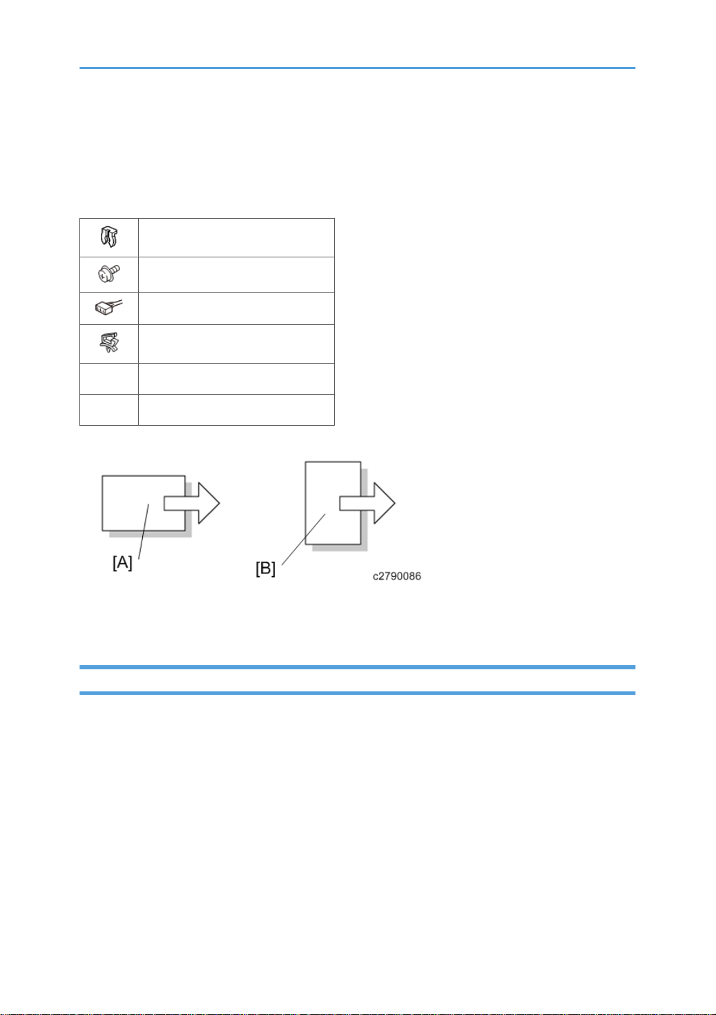
SEF Short Edge Feed
LEF Long Edge Feed
[A] Short Edge Feed (SEF)
[B] Long Edge Feed (LEF)
Trademarks
Microsoft®, Windows®, and MS-DOS® are registered trademarks of Microsoft Corporation in the
United States and /or other countries.
PostScript® is a registered trademark of Adobe Systems, Incorporated.
PCL® is a registered trademark of Hewlett-Packard Company.
Ethernet® is a registered trademark of Xerox Corporation.
PowerPC® is a registered trademark of International Business Machines Corporation.
Other product names used herein are for identification purposes only and may be trademarks of their
respective companies. We disclaim any and all rights involved with those marks.
2

The Aim of Anti-tip Components and Precautions
The anti-tip components are necessary for meeting the requirements of IEC60950-1, the international
standard for safety.
The aim of these components is to prevent the products, which are heavy in weight, from toppling as a
result of people running into or leaning onto the products, which can lead to serious accidents such as
persons becoming trapped under the product. (U.S.: UL60950-1, Europe: EN60950-1)
Therefore, removal of such components must always be with the consent of the customer.
Do not remove them at your own judgment.
3

TABLE OF CONTENTS
Revision Lists........................................................................................................................................................1
Safety and Symbols............................................................................................................................................2
Trademarks.....................................................................................................................................................2
The Aim of Anti-tip Components and Precautions.......................................................................................3
1. Replacement and Adjustment
Exterior Parts.......................................................................................................................................................7
Front Cover.....................................................................................................................................................7
Inner Cover.....................................................................................................................................................7
Rear Cover......................................................................................................................................................9
Front Left Cover............................................................................................................................................10
Upper Cover................................................................................................................................................10
Upper Front Cover.......................................................................................................................................11
Upper Rear Cover.......................................................................................................................................12
Proof Tray.....................................................................................................................................................13
Shift Tray.......................................................................................................................................................14
Booklet Tray.................................................................................................................................................15
Upper Left Cover..........................................................................................................................................15
Left Center Cover.........................................................................................................................................15
Left Lower Cover..........................................................................................................................................16
Main Unit..........................................................................................................................................................18
Paper Eject Cover Open/Close Motor.....................................................................................................18
Paper Guide Plate Open/Close HP Sensor..............................................................................................18
Proof Tray Full Sensor..................................................................................................................................19
Proof Tray Paper Eject Sensor.....................................................................................................................19
Entrance Sensor...........................................................................................................................................20
Intermediate Transport Sensor Right...........................................................................................................20
Intermediate Transport Sensor Left.............................................................................................................22
Shift Tray Paper Surface Sensor.................................................................................................................22
Shift Tray Upper Limit Switch.......................................................................................................................23
Shift Tray Paper Eject Sensor......................................................................................................................24
Proof Transport Motor.................................................................................................................................24
Positioning Roller Motor..............................................................................................................................25
Shift Motor....................................................................................................................................................25
4

Paper Eject Transport Motor.......................................................................................................................26
Paper Bundle Transport Upper Motor.......................................................................................................26
Stapler Tray..................................................................................................................................................29
Stapler Tray Paper Detection Sensor.........................................................................................................31
Paper Bundle Transport Upper Pressure Release HP sensor....................................................................32
Release Claw HP Sensor.............................................................................................................................33
Jogger HP Sensor.........................................................................................................................................
Jogger Motor...............................................................................................................................................34
Paper Bundle Transport Upper Pressure Release Motor..........................................................................34
Release Claw Motor....................................................................................................................................35
Boards...............................................................................................................................................................37
Main Control Board....................................................................................................................................37
Booklet Stapler Unit.........................................................................................................................................38
Stapler Unit...................................................................................................................................................38
Booklet Stapler Unit.....................................................................................................................................45
Center-Folding Unit......................................................................................................................................46
Center-Folding Tray Paper Eject Sensor....................................................................................................48
Trailing Edge Stopper Transport Sensor....................................................................................................49
Trailing Edge Stopper HP Sensor...............................................................................................................50
Center-Folding Blade HP Sensor................................................................................................................51
Center-Folding Cam HP Sensor..................................................................................................................51
Trailing Edge Stopper Motor......................................................................................................................52
Folding Blade Motor...................................................................................................................................53
33
Folding Transport Motor.............................................................................................................................53
Center-Folding Tray Full Sensors 1, 2........................................................................................................54
Stapler Transfer Motor (Middle)................................................................................................................55
Paper Bundle Transport Lower Pressure Release HP Sensor....................................................................56
5

6

1. Replacement and Adjustment
Exterior Parts
Front Cover
1. Open the front cover [A].
2. Front cover ( ×1)
Inner Cover
1. Open the front cover (page 7)
7

1. Replacement and Adjustment
2. Remove the three knobs (hook×1 for each).
Use a flathead screwdriver to release the hooks of the knobs if the knobs have the hooks to
•
lock.
3. Remove the three screws on the inner cover [A] ( ×3).
4. Pull the booklet stitch unit [A].
8

5. Inner cover [B] ( ×1)
Exterior Parts
Rear Cover
1. Rear cover [A] ( ×2)
9

1. Replacement and Adjustment
Front Left Cover
1. Front cover (page 7)
2. Inner cover (page 7)
3. Front left cover [A] ( ×2)
Upper Cover
10
1. Open the upper cover [A].

2. Upper cover [A] ( ×2, hook x 1)
• When reattaching the upper cover, attach the clips so that their tabs face forward.
Exterior Parts
Upper Front Cover
1. Front left cover (page 10)
2. Upper cover (page 10)
11

1. Replacement and Adjustment
3. Upper front cover [A] ( ×3)
Upper Rear Cover
1. Rear cover (page 9)
2. Upper cover (page 10)
12

3. Upper rear cover [A] ( ×3)
Exterior Parts
Proof Tray
1. Upper front cover (page 11)
2. Upper rear cover (page 12)
13

1. Replacement and Adjustment
3. Proof tray [A] ( ×2)
Shift Tray
1. Shift tray [A] ( ×1)
14

Booklet Tray
1. Booklet tray [A]
Upper Left Cover
Exterior Parts
1. Upper left cover [A] ( ×2)
Left Center Cover
1. Front cover (page 7)
2. Rear cover (page 9)
3. Shift tray (page 14)
4. Shift tray front bracket [B] ( ×2)
15

1. Replacement and Adjustment
5. Shift tray bracket [A] with the shift tray rear bracket [C]
6. Left center cover [A] ( ×2)
Left Lower Cover
1. Front cover (page 7)
2. Rear cover (page 9)
3. Booklet tray (page 15)
16
 Loading...