

Ricoh SR3130 Field Service Manual

Internal Finisher SR3130
Machine Code: D690
Field Service Manual
July, 2014
Subject to change


Revision Lists
Version Section Details
Initial release of this document.
1.00 -
Created this manual for D176/D177
series.
1.10
Revised all sections according to the
release of D197 series.
Modified some parts name.
Added the following sections:
All
Read This First > Safety and Symbols Modified some icons.
Replacement and Adjustment > Inner
Finisher
Replacement and Adjustment > Covers
and Trays > Finisher Upper Cover
> Covers and Trays
> Control Board
> Sensors
> Motors
> Stapler Unit
Changed the pictures for Step 1 Step 3,
Step 4, and Step 5.
Added items need to be removed in Step
4.
Deleted some steps.
Replacement and Adjustment > Covers
and Trays > Finisher Rear Cover
Replacement and Adjustment > Covers
and Trays > Paper Output Tray
Replacement and Adjustment >
Control Board
Replacement and Adjustment >
Sensors > Entrance Sensor
Deleted all steps
Deleted some steps
Added items need to be removed in Step
2.
Deleted some steps.
Added the picture, and items need to be
removed in Step 3
1

Version Section Details
Replacement and Adjustment >
Sensors > Paper Exit Full Sensor
Replacement and Adjustment >
Sensors > Paper Bail Home Position
Sensor
Replacement and Adjustment >
Sensors > Paper Surface Detection
Sensor
Replacement and Adjustment >
Sensors > Transport Sensor
Replacement and Adjustment >
Sensors > Strike Roller Home Position
Sensor
Replacement and Adjustment >
Sensors > Paper Output Guide Plate
Home Position Sensor
Replacement and Adjustment >
Sensors > Shift Roller Home Position
Sensor
Added the picture, and items need to be
removed in Step 2.
Added the picture, and items need to be
removed in Step 2.
Added the picture, and items need to be
removed in Step 4.
Added the picture, and items need to be
removed in Step 2.
Added the picture, and items need to be
removed in Step 4.
Added the picture, and items need to be
removed in Step 3.
Modified items need to be removed in Step
2.
Deleted some steps
Replacement and Adjustment >
Sensors > Stapler Home Position
Sensor
Replacement and Adjustment >
Sensors > Jogger Fence Home Position
Sensor (Front)
Replacement and Adjustment >
Sensors > Jogger Fence Home Position
Sensor (Rear)
Replacement and Adjustment >
Sensors > Stapler Tray Jam Detection
Sensor
2
Added the picture, and items need to be
removed in Step 4.
Modified a Note for Step 5.
Added the picture, and items need to be
removed in Step 2.
Added the picture, and items need to be
removed in Step 2.
Added the picture, and items need to be
removed in Step 3.
Added items need to be removed in Step
4.

Version Section Details
Replacement and Adjustment >
Sensors > Paper Detection Sensor
Replacement and Adjustment > Motors
> Entrance Motor
Replacement and Adjustment > Motors
> Tray Lift Motor
Replacement and Adjustment > Motors
> Paper Bail Motor
Replacement and Adjustment > Motors
> Paper Output Guide Plate Motor
Replacement and Adjustment > Motors
> Strike Roller Motor
Replacement and Adjustment > Motors
> Shift Motor
Added the picture, and items need to be
removed in Step 3.
Modified a Note for Step 4.
Deleted some steps
Added the picture, and items need to be
removed in Step 3.
Added the picture, and items need to be
removed in Step 2 and Step 3.
Added the picture, and items need to be
removed in Step 2.
Added the picture, and items need to be
removed in Step 2.
Added the picture, and items need to be
removed in Step 4
Deleted some steps
Added the picture, and items need to be
removed in Step 2 and Step 3.
Replacement and Adjustment > Motors
> Stapler Displacement Motor
Replacement and Adjustment > Motors
> Jogger Fence Motor (Front / Rear)
Replacement and Adjustment > Motors
> Transport Motor
Modified the procedure.
Add a Note in Step 3.
Added the picture, and items need to be
removed in Step 4.
Added the picture, and items need to be
removed in Step 2 and Step 3.
Added the picture, and items need to be
removed in Step 4 and Step 5.
3

Version Section Details
Added the picture, and items need to be
removed in Step 3.
Added items need to be removed in Step
4.
Replacement and Adjustment > Motors
> Paper Output Motor
Modified Step 5
Added the picture, and items need to be
removed in Step 5.
Added the picture, and items need to be
removed in Step 6
4
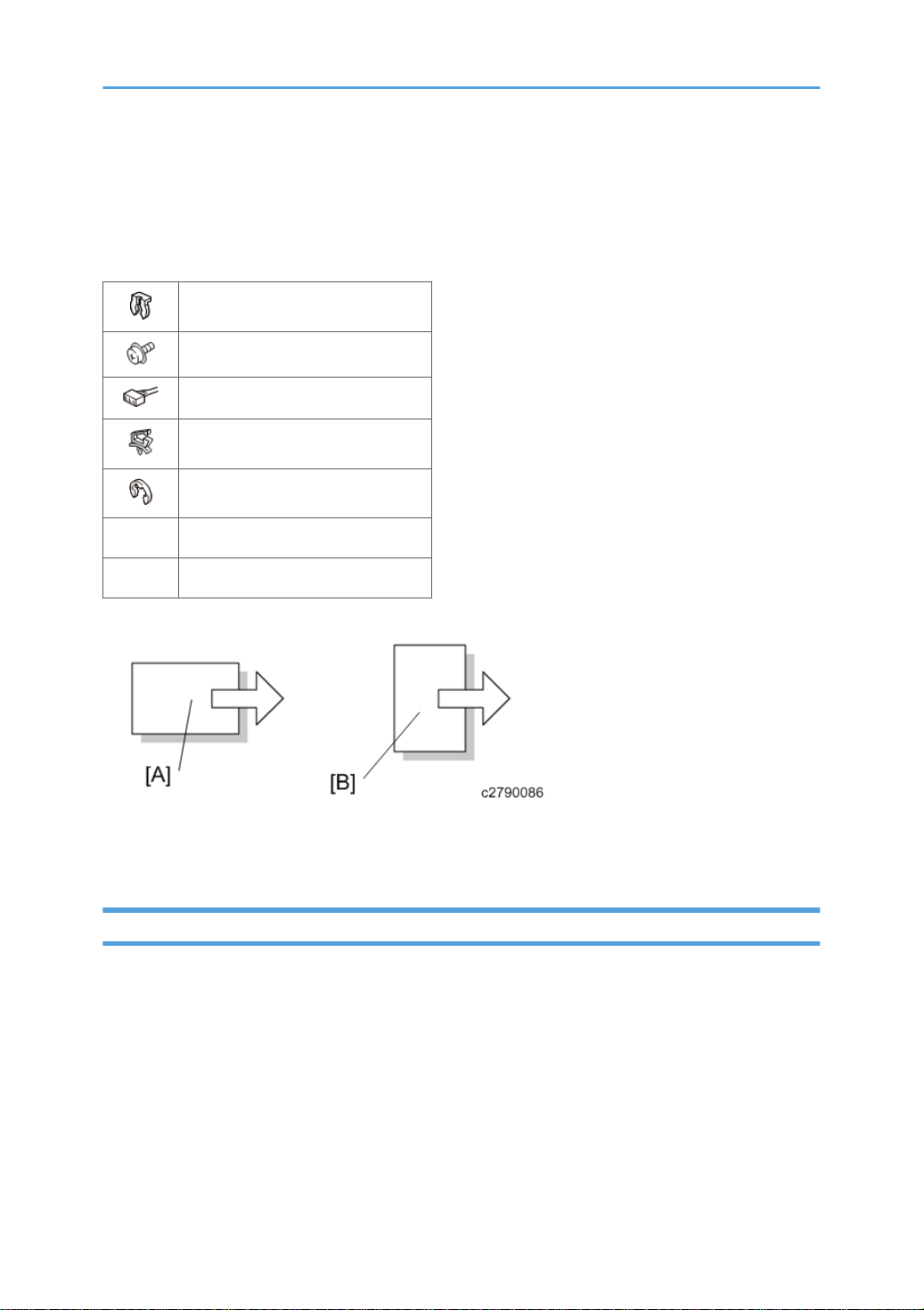
Safety and Symbols
This manual uses several symbols and abbreviations. The meaning of those symbols and abbreviations
are as follows:
Clip ring
Screw
Connector
Clamp
E-ring
SEF Short Edge Feed
LEF Long Edge Feed
[A] Short Edge Feed (SEF)
[B] Long Edge Feed (LEF)
Trademarks
Microsoft®, Windows®, and MS-DOS® are registered trademarks of Microsoft Corporation in the
United States and /or other countries.
PostScript® is a registered trademark of Adobe Systems, Incorporated.
PCL® is a registered trademark of Hewlett-Packard Company.
Ethernet® is a registered trademark of Xerox Corporation.
PowerPC® is a registered trademark of International Business Machines Corporation.
Other product names used herein are for identification purposes only and may be trademarks of their
respective companies. We disclaim any and all rights involved with those marks.
5

The Aim of Anti-tip Components and Precautions
The anti-tip components are necessary for meeting the requirements of IEC60950-1, the international
standard for safety.
The aim of these components is to prevent the products, which are heavy in weight, from toppling as a
result of people running into or leaning onto the products, which can lead to serious accidents such as
persons becoming trapped under the product. (U.S.: UL60950-1, Europe: EN60950-1)
Therefore, removal of such components must always be with the consent of the customer.
Do not remove them at your own judgment.
6

TABLE OF CONTENTS
Revision Lists........................................................................................................................................................1
Safety and Symbols............................................................................................................................................5
Trademarks.....................................................................................................................................................5
The Aim of Anti-tip Components and Precautions.......................................................................................6
1. Replacement and Adjustment
Inner Finisher.......................................................................................................................................................9
Covers and Trays.............................................................................................................................................12
Finisher Front Cover.....................................................................................................................................12
Finisher Upper Cover...................................................................................................................................13
Finisher Rear Cover......................................................................................................................................14
Paper Output Tray.......................................................................................................................................14
Paper Output Cover....................................................................................................................................15
Control Board...................................................................................................................................................16
Sensors..............................................................................................................................................................18
Entrance Sensor...........................................................................................................................................18
Paper Exit Full Sensor..................................................................................................................................19
Paper Bail Home Position Sensor...............................................................................................................19
Paper Surface Detection Sensor.................................................................................................................20
Transport Sensor..........................................................................................................................................20
Strike Roller Home Position Sensor.............................................................................................................21
Paper Output Guide Plate Home Position Sensor.....................................................................................23
Shift Roller Home Position Sensor...............................................................................................................24
Stapler Home Position Sensor.....................................................................................................................25
Jogger Fence Home Position Sensor (Front)..............................................................................................27
Jogger Fence Home Position Sensor (Rear)..............................................................................................28
Stapler Tray Jam Detection Sensor.............................................................................................................29
Paper Detection Sensor...............................................................................................................................30
Motors...............................................................................................................................................................33
Entrance Motor............................................................................................................................................33
Tray Lift Motor..............................................................................................................................................33
Paper Bail Motor..........................................................................................................................................35
Paper Output Guide Plate Motor...............................................................................................................35
Strike Roller Motor.......................................................................................................................................35
7

Shift Motor....................................................................................................................................................36
Stapler Displacement Motor.......................................................................................................................38
Jogger Fence Motor (Front / Rear)............................................................................................................40
Transport Motor...........................................................................................................................................42
Paper Output Motor....................................................................................................................................43
Stapler Unit.......................................................................................................................................................45
8
1. Replacement and Adjustment
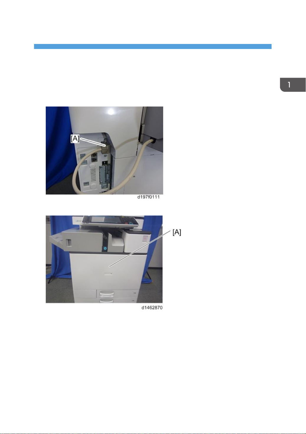
Inner Finisher
1. Interface cable [A].
2. Open the front cover [A].
9
1. Replacement and Adjustment
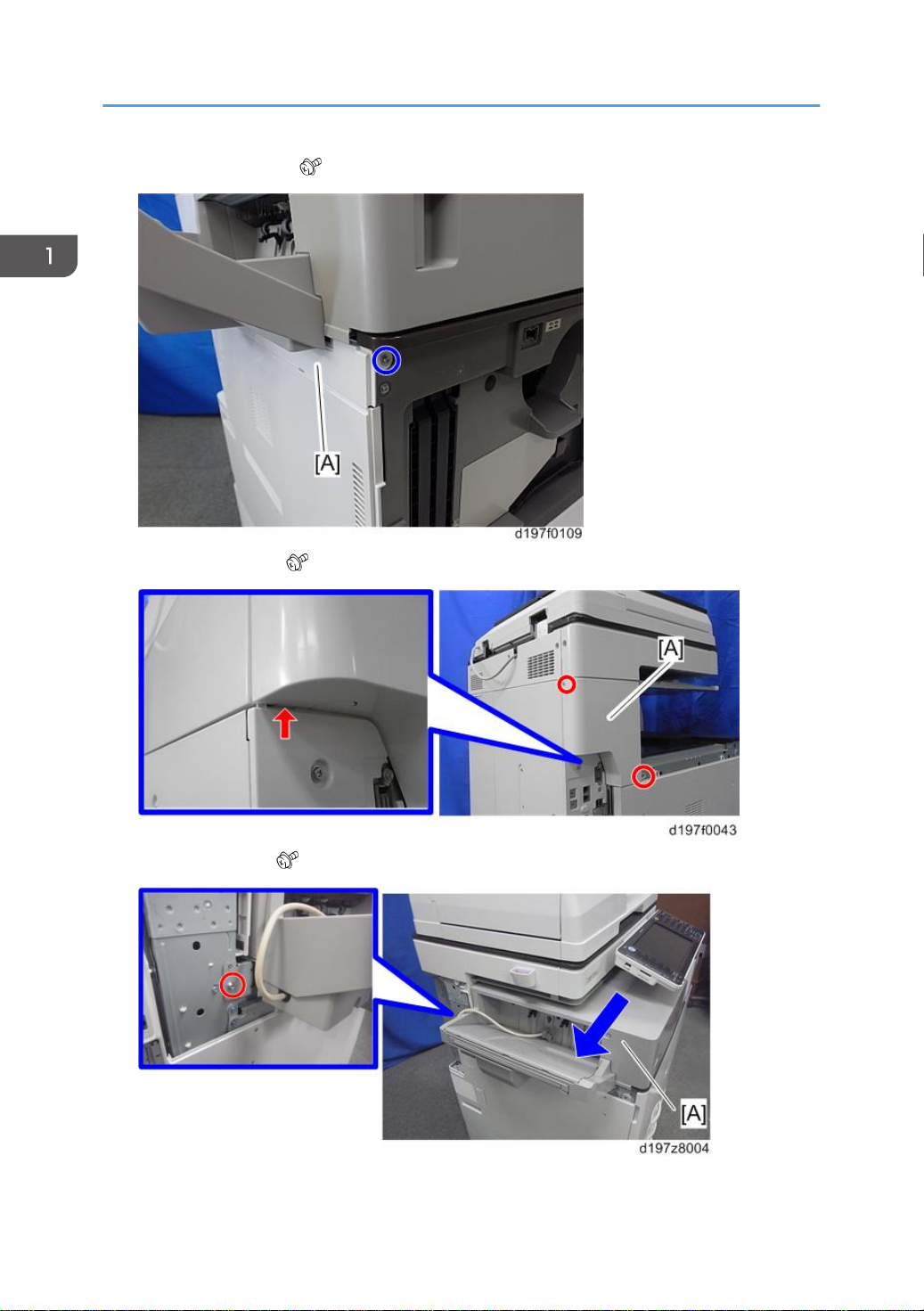
3. Left upper cover [A] ( ×1).
4. Left rear cover [A] ( ×2, hook×1).
10
5. Inner finisher [A] ( ×1).
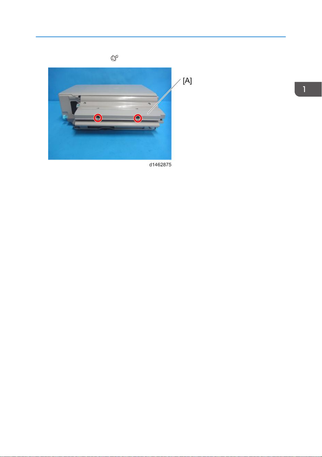
6. Bridge guide plate [A] ( ×2).
Inner Finisher
11
1. Replacement and Adjustment
Covers and Trays
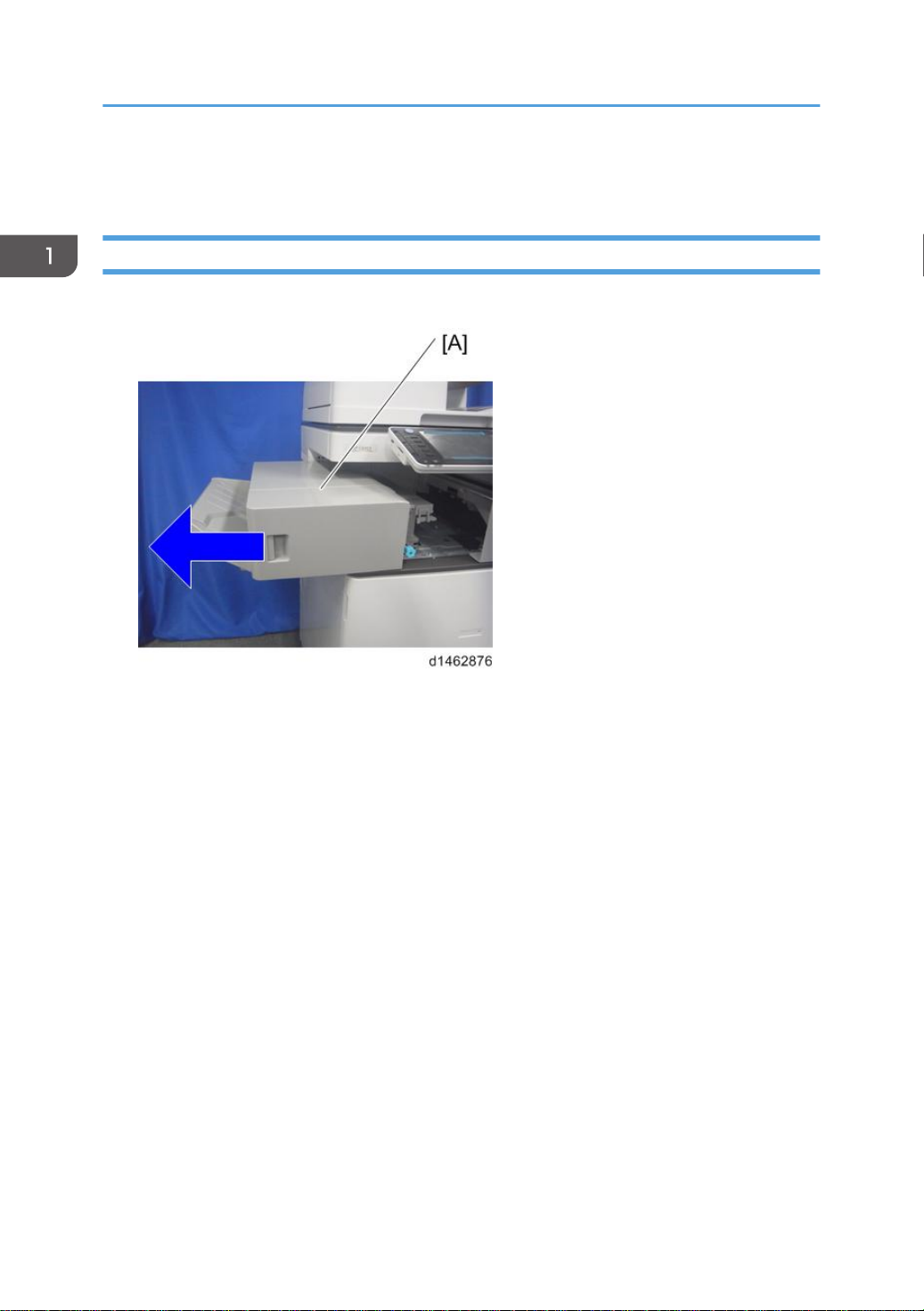
Finisher Front Cover
1. Pull the finisher [A].
12

2. Finisher front cover [A] ( ×2).
Covers and Trays
Finisher Upper Cover
1. Finisher front cover (page 12).
2. Finisher upper cover [A] ( ×2).
13
 Loading...