

Page 1

User Guide
Getting Started
Selected Version
Copy
Fax
Print
Scan
Document Server
Web Image Monitor
Adding Paper and Toner
Troubleshooting
Information for This Machine
For information not found in this manual,
see the online manuals available on our
web site (https://www.ricoh.com/) or via the
control panel.
For safe and correct use, be sure to read Safety Information before
using the machine.
Page 2

Page 3
TABLE OF CONTENTS
How to Read This Manuals................................................................................................................................7
Symbols Used in This Manuals......................................................................................................................7
1. Getting Started
Names of Major Features..................................................................................................................................9
Model-Specific Information.............................................................................................................................10
Guide to Names and Functions of Components............................................................................................11
Guide to Components................................................................................................................................. 11
Connecting and Setting the Network............................................................................................................. 18
Setting Wired LAN.......................................................................................................................................18
Setting Wireless LAN...................................................................................................................................20
Connecting the USB Interface......................................................................................................................... 30
Connecting to the USB (Type B) Interface................................................................................................. 30
Connecting a Device to the Machine's USB Host Interface..................................................................... 30
Connecting the Machine to a Telephone Line and Telephone/Handset....................................................32
Connecting the Telephone Line (mainly Europe and Asia).................................................. 32
Connecting the Telephone Line (mainly North America)......................................................33
Selecting the Line Type................................................................................................................................34
Settings Needed for Each Function................................................................................................................ 36
Guide to Functions of the Machine's External Options (mainly Europe and Asia).................37
Guide to Functions of the Machine's External Options (mainly North America).................... 38
Order of Option Installation............................................................................................................................39
Attaching the Paper Feed Unit........................................................................................................................ 40
The number of tray that you can install...................................................................................................... 41
Installing the Offline Stapler............................................................................................................................ 43
Installing the Wireless LAN interface board.................................................................................................. 47
Installing the IEEE 1284 interface board....................................................................................................... 48
Connecting to the IEEE 1284 Interface..................................................................................................... 49
Installing the Extended USB board.................................................................................................................50
Installing the USB device server......................................................................................................................51
Procedure for installing the USB device server..........................................................................................51
Connecting to the Extra Ethernet Interface with the USB Device Server Option.................................... 52
Specifying an IP address for the USB Device Server................................................................................54
Installing the File Format Converter................................................................................................................ 57
1
Page 4

Installing SD Card Options..............................................................................................................................58
Installing the Handset (mainly North America).........................................................................60
Connecting the handset...............................................................................................................................60
Connecting the telephone........................................................................................................................... 64
Guide to the Names and Functions of the Machine's Control Panel........................................................... 65
Changing the Display Language.................................................................................................................... 66
How to Use the [Home] Screen...................................................................................................................... 67
Possible Operations on the Standard Application Screen....................................................................... 69
Adding Shortcuts to the [Home] Screen.....................................................................................................71
Adding Shortcuts to Bookmarks on the [Home] Screen............................................................................71
Adding Shortcuts to Programs to the [Home] Screen............................................................................... 72
Adding Widgets to the [Home] Screen......................................................................................................72
How to Use Each Application......................................................................................................................... 73
[Copy] (standard) Screen........................................................................................................................... 74
[Fax] (standard) Screen.............................................................................................................................. 76
[Scanner] (standard) Screen.......................................................................................................................82
Registering Frequently Used Functions........................................................................................................... 88
Turning On/Off the Power..............................................................................................................................91
Turning On/Off the Main Power................................................................................................................91
Logging In the Machine...................................................................................................................................93
User Code Authentication........................................................................................................................... 93
Logging In/Out Using the Control Panel...................................................................................................93
Placing Originals..............................................................................................................................................95
Placing Originals on the Exposure Glass...................................................................................................95
Placing Originals in the Auto Document Feeder....................................................................................... 95
2. Copy
Basic Procedure................................................................................................................................................97
Auto Reduce / Enlarge....................................................................................................................................98
Duplex Copying............................................................................................................................................... 99
Specifying the Original and Copy Orientation...................................................................................... 100
Combined Copying.......................................................................................................................................102
One-Sided Combine.................................................................................................................................103
Two-Sided Combine................................................................................................................................. 104
2
Page 5

Copying Onto Custom Size Paper...............................................................................................................106
Copying onto Envelopes...............................................................................................................................107
Sort..................................................................................................................................................................108
Changing the Number of Sets..................................................................................................................108
Storing Data in the Document Server...........................................................................................................109
3. Fax
Basic Procedure for Fax Transmissions (Memory Transmission)................................................................111
Registering a Fax Destination................................................................................................................... 111
Changing or Deleting a Fax Destination................................................................................................. 114
Transmitting while Checking Connection to Destination (Immediate Transmission).................................116
Canceling a Fax Transmission...................................................................................................................... 117
Canceling a Transmission Before the Original Is Scanned....................................................................117
Canceling a Transmission While the Original Is Being Scanned.......................................................... 117
Canceling a Transmission After the Original Is Scanned.......................................................................117
Storing a Fax Document................................................................................................................................119
Sending Stored Fax Documents...............................................................................................................120
Printing the Records Manually......................................................................................................................122
4. Print
Installing the Printer Driver for Network Connection (Windows)...............................................................123
Installing the PCL 6 Printer Driver from the CD-ROM.............................................................................123
Installing the Printer Driver for USB Connection (Windows)......................................................................127
Installing the Printer Driver from the CD-ROM........................................................................................127
Displaying the Printer Driver Properties........................................................................................................130
Standard Printing........................................................................................................................................... 131
When Using the PCL 6 Printer Driver....................................................................................................... 131
Printing on Both Sides of Sheets................................................................................................................... 135
How to Print on Both Sides of the Paper (When Using the PCL 6 Printer Driver)................................. 135
Combining Multiple Pages into Single Page............................................................................................... 136
How to Print Multiple Pages onto a Single Sheet (When Using the PCL 6 Printer Driver)...................136
Printing on Envelopes.................................................................................................................................... 138
Configuring Envelope Settings Using the Control Panel........................................................................ 138
Printing on Envelopes Using the Printer Driver........................................................................................ 138
Saving and Printing Using the Document Server.........................................................................................139
3
Page 6

Storing Documents in Document Server.................................................................................................. 139
Managing Documents Stored in Document Server................................................................................ 140
Using the Quick Print Release Function........................................................................................................141
Using the Print/Scan(Memory Storage Device) Function..........................................................................143
5. Scan
Basic Procedure When Using Scan to Folder............................................................................................. 147
Creating a Shared Folder on a Computer Running Windows/Confirming a Computer's Information.....
.................................................................................................................................................................... 147
Registering an SMB Folder.......................................................................................................................150
Deleting an SMB registered folder.......................................................................................................... 154
Entering the Path to the Destination Manually........................................................................................ 155
Basic Procedure for Sending Scan Files by E-mail......................................................................................156
Registering an E-mail Destination.............................................................................................................156
Changing or Deleting an E-mail Destination...........................................................................................158
Entering an E-mail Address Manually..................................................................................................... 159
Basic Procedure for Storing Scan Files........................................................................................................ 160
Checking a Stored File Selected from the List......................................................................................... 162
Specifying the File Type................................................................................................................................ 164
Specifying Scan Settings...............................................................................................................................165
6. Document Server
Storing Data................................................................................................................................................... 167
Printing Stored Documents............................................................................................................................ 170
7. Web Image Monitor
Displaying Top Page..................................................................................................................................... 173
8. Adding Paper and Toner
Loading Paper................................................................................................................................................175
Loading Paper into Paper Trays............................................................................................................... 175
Loading Paper into the Bypass Tray........................................................................................................ 178
Loading Orientation-fixed Paper or Two-sided Paper...........................................................................180
Specifying the Paper Setting for the Bypass Tray................................................................................... 183
Recommended Paper.................................................................................................................................... 186
When Loading Thick Paper...................................................................................................................... 192
When Loading Envelopes.........................................................................................................................193
4
Page 7

Adding Toner................................................................................................................................................. 196
Faxing/Scanning Operations When Toner Has Run Out..................................................................... 198
Disposing of Used Print Cartridge............................................................................................................198
9. Troubleshooting
When a Status Icon Is Displayed on the Control Panel..............................................................................201
When the Indicator Lamp for [Check Status] Is Lit or Flashing...................................................................202
When the Machine Makes a Beeping Sound.............................................................................................204
When You Have Problems Operating the Machine...................................................................................206
When Multiple Functions Cannot Be Executed Simultaneously............................................................ 212
Messages Displayed When You Use the Copy/Document Server Function...........................................213
Messages Displayed When You Use the Fax Function..............................................................................215
Messages Displayed on the Control Panel When You Use the Printer Function......................................225
Messages Printed on the Error Logs or Reports When You Use the Printer Function............................... 228
Messages Displayed on the Control Panel When You Use the Scanner Function...................................237
Messages Displayed on the Client Computer When You Use the Scanner Function..............................248
When Other Messages Appear...................................................................................................................254
Cautions in Removing Jammed Paper..........................................................................................................262
Removing Jammed Paper..............................................................................................................................268
Locating Jammed Paper............................................................................................................................269
10. Information for This Machine
ENERGY STAR Program................................................................................................................................271
Energy Saving Functions............................................................................................................................... 272
User Information on Electrical and Electronic Equipment (mainly Europe).......................... 274
Users in the countries where this symbol shown in this section has been specified in national law on
collection and treatment of E-waste.........................................................................................................274
All Other Users.......................................................................................................................................... 274
For Users in India.......................................................................................................................................274
For Turkey Only.........................................................................................................................................275
Note for the Battery and/or Accumulator Symbol (For EU countries only) (mainly Europe).....
.........................................................................................................................................................................276
Environmental Advice for Users (mainly Europe)....................................................................277
Users in the EU, Switzerland and Norway............................................................................................. 277
Notes to users in the state of California (Notes to Users in USA) (mainly North America). 278
5
Page 8

Specifications for the Main Unit................................................................................................................... 279
Specifications for the Document Server....................................................................................................... 285
Specifications for Facsimile...........................................................................................................................286
Fax Transmission and Reception.............................................................................................................. 286
IP-Fax Transmission and Reception..........................................................................................................286
Internet Fax Transmission and Reception................................................................................................ 287
E-mail Transmission and Reception, and Folder Transmission...............................................................288
Specifications for Printer................................................................................................................................290
Specifications for Scanner............................................................................................................................ 292
Specifications for Lower Paper Tray (250 sheets)...................................................................................... 295
Specifications for Lower Paper Tray (500 sheets)...................................................................................... 296
Specifications for IEEE 1284 Interface Board.............................................................................................297
Specifications for Wireless LAN Interface Board........................................................................................298
Specifications for Auto Document Feeder................................................................................................... 300
Specifications for USB Device Server.......................................................................................................... 301
INDEX...........................................................................................................................................................303
6
Page 9
How to Read This Manuals
Symbols Used in This Manuals
This manual uses the following symbols:
Indicates points to pay attention to when using functions. This symbol indicates points that may result in
the product or service becoming unusable or result in the loss of data if the instructions are not obeyed.
Be sure to read these explanations.
Indicates supplementary explanations of the machine's functions, and instructions on resolving user
errors.
Indicates where you can find further relevant information.
[ ]
Indicates the names of keys or buttons on the product or display.
(mainly Europe and Asia), (mainly Europe), or (mainly Asia)
(mainly North America)
Differences in the functions of Region A and Region B models are indicated by two symbols. Read the
information indicated by the symbol that corresponds to the region of the model you are using. For
details about which symbol corresponds to the model you are using, see page 10 "Model-Specific
Information" .
7
Page 10

8
Page 11

1. Getting Started
This chapter describes how to start using this machine.
Names of Major Features
In this manual, major features of the machine are referred to as follows:
• Auto Document Feeder
ADF
9
Page 12
DVL351
1. Getting Started
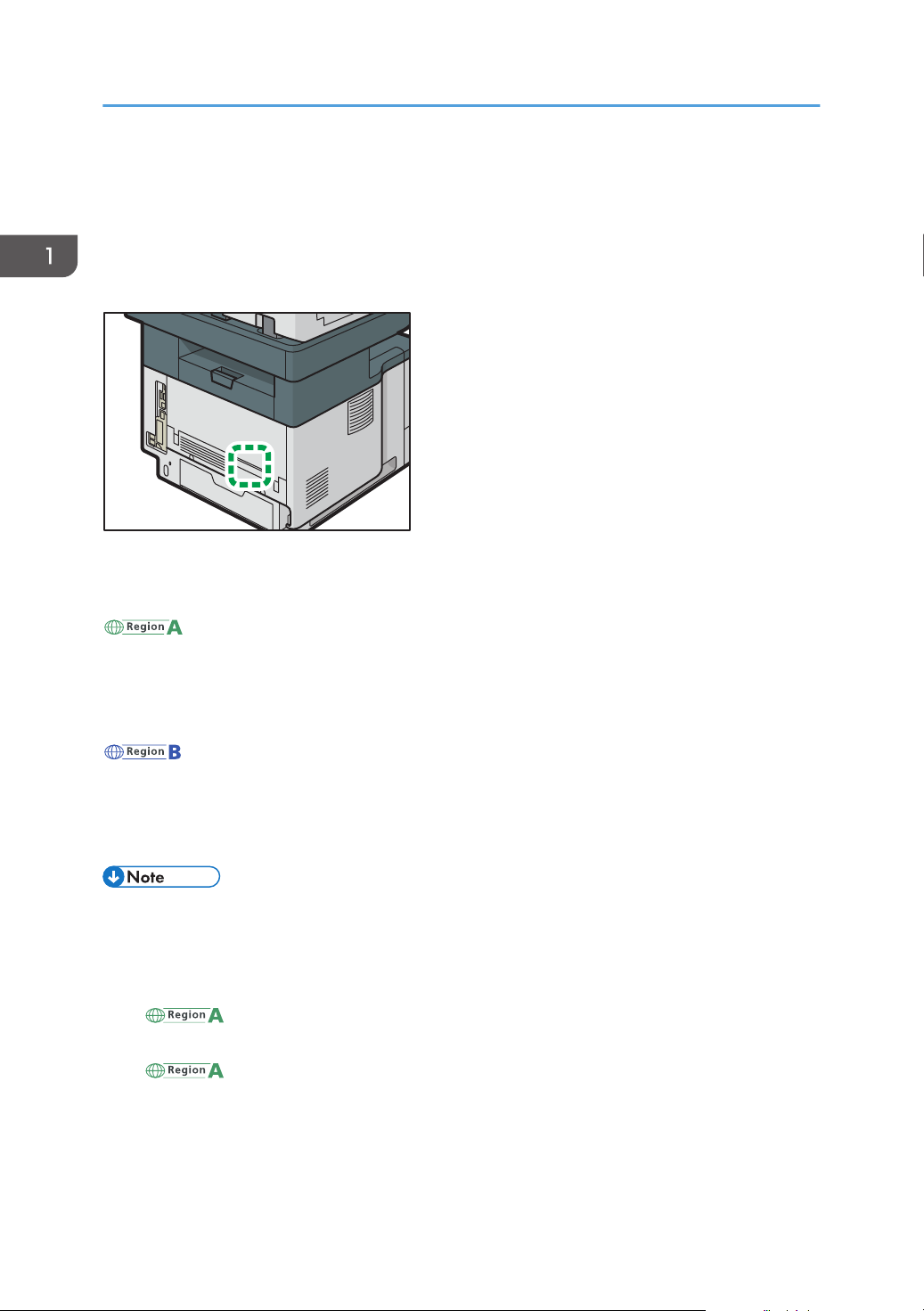
Model-Specific Information
This section explains how you can identify the region your machine belongs to.
There is a label on the rear of the machine, located in the position shown below. The label contains
details that identify the region your machine belongs to. Read the label.
The following information is region-specific. Read the information under the symbol that corresponds to
the region of your machine.
(mainly Europe and Asia)
If the label contains the following, your machine is a region A model:
• CODE XXXX -27, -29
• 220–240 V
(mainly North America)
If the label contains the following, your machine is a region B model:
• CODE XXXX -17
• 120–127 V
• Dimensions in this manual are given in two units of measure: metric and inch. If your machine is a
Region A model, refer to the metric units. If your machine is a Region B model, refer to the inch
units.
• If your machine is a region A model and "CODE XXXX -27" is printed on the label, see
" (mainly Europe)" also.
• If your machine is a region A model and "CODE XXXX -29" is printed on the label, see
" (mainly Asia)" also.
10
Page 13
Guide to Names and Functions of Components
Guide to Names and Functions of Components
Guide to Components
• Do not obstruct the machine's vents. Doing so risks fire caused by overheated internal
components.
• Do not press or hit the staple unit strongly. Doing so may damage it. If stapling fails after the stapler
has been forcefully hit, the staples in the cartridge may be broken.
• Do not hold the staple unit when you move the machine.
11
Page 14
22
20
21
18
15
16
17
19
14
11
11
13
9
10
12
312 4 5
6
7
8
DVL352
1. Getting Started
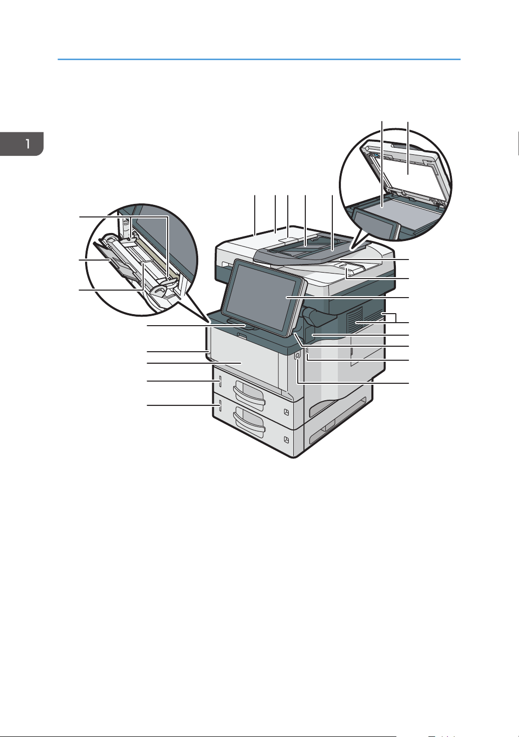
Front and right view
1. ADF
Lower the ADF over originals placed on the exposure glass.
If you load a stack of originals in the ADF, the ADF will automatically feed the originals one by one.
2. ADF cover
Open this cover to remove originals jammed in the ADF.
3. ADF cover open lever
Pull this lever to open the ADF cover.
4. Input tray for the ADF
Place stacks of originals here.
12
Page 15

Guide to Names and Functions of Components
5. Extender for the ADF tray
Extend this when placing paper longer than A4 in the input tray for ADF.
6. Exposure glass
Place originals face down here.
7. Cover for the exposure glass
Open this cover to place originals on the exposure glass.
8. Output tray for the ADF
Originals scanned with the ADF are output here.
9. Stop fence for the ADF
Pull out this fence to prevent originals from falling off.
10. Control panel
See page 65 "Guide to the Names and Functions of the Machine's Control Panel".
11. Ventilation holes
Prevent overheating.
12. Cover for installing an offline stapler
Remove when you install the offline stapler.
13. Internal tray
Copied/printed paper and fax messages are delivered here.
14. Front cover open button
Push this button to open the front cover.
15. Lower paper tray
Load paper here.
For details, see page 37 "Guide to Functions of the Machine's External Options (mainly Europe
and Asia)" or page 38 "Guide to Functions of the Machine's External Options (mainly North
America)".
16. Tray 1
Load paper here.
17. Front cover
Open to access the inside of the machine and remove jammed paper.
Open here to replace the print cartridge and the drum unit.
18. Main power switch
To operate the machine, the main power switch must be on. If it is off, turn the switch on.
See page 91 "Turning On/Off the Power".
19. Stop fence
Pull this fence to prevent paper from falling off.
20. Bypass tray
Use to copy or print on thick paper, OHP transparencies, envelopes, and label paper (adhesive labels).
13
Page 16
DVL267
6
7
8
9
10
11
1
435
2
2
1. Getting Started
21. Extender for the bypass tray
Pull this extender out when loading A4 , 81/2 × 11 or larger size paper in the bypass tray.
22. Paper guides
When loading paper in the bypass tray, align the paper guides flush against the paper.
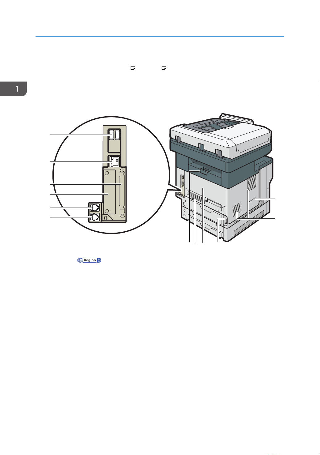
Rear and left view
14
1. Handset slit (mainly North America)
Attach the handset bracket to the slit.
2. Vents
Prevent overheating.
3. Power connector
Connect the power cord to the machine. Insert the other end into an electrical outlet.
4. Rear cover
Open to access the inside of the machine and remove jammed paper.
Open here to replace the fusing unit.
5. Rear cover open lever
Pull this lever to open the rear cover.
6. External telephone connector
For connecting an external telephone.
7. G3 interface unit connector
For connecting a telephone line.
Page 17

8. Slot
DVL354
1
2
Optional interface boards can be inserted.
9. Expansion card slots
Remove the cover to install SD cards.
10. Ethernet port
Use a network interface cable to connect the machine to a network.
11. USB Host Interface
Connect external devices such as a card authentication device.
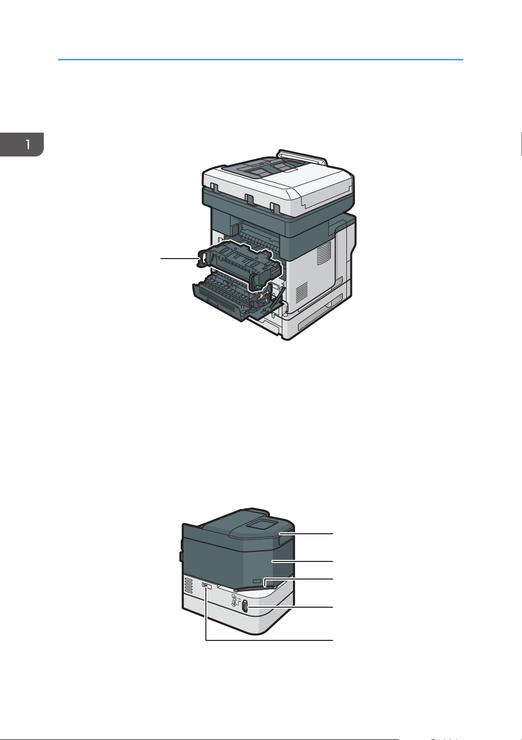
Interior: Front view
Guide to Names and Functions of Components
1. Print cartridge
To remove jammed paper, pull out the print cartridge and drum unit as a single unit.
Messages appear on the screen when the print cartridge needs to be replaced, or a new cartridge needs to
be prepared.
For details about the messages that appear on the screen when consumables need to be replaced, see
"Adding Toner", Maintenance.
When you remove jammed paper, pull out the print cartridge with the drum unit. If you want to remove only
the print cartridge, pull down the lever on the left side of the print cartridge, and then pull the print cartridge
out.
2. Drum unit
Messages appear on the screen when the drum unit needs to be replaced, or a new drum unit needs to be
prepared.
For details about the messages that appear on the screen when consumables need to be replaced, see
"Replacing the Drum Unit", Maintenance.
15
Page 18
DVL355
1
3
4
5
2
1
DVL425
1. Getting Started
For IM 350F, IM 350, IM 430F:
When the drum unit needs to be replaced, contact your service representative.
Interior: Rear view
1. Fusing unit
Pull out the fusing unit and remove jammed paper.
Messages appear on the screen when the fusing unit needs to be replaced, or a new fusing unit needs to be
prepared.
For details about the messages that appear on the screen when consumables need to be replaced, see
"Replacing the Maintenance Kit", Maintenance.
For IM 350F, IM 350, IM 430F:
When the fusing unit needs to be replaced, contact your service representative.
Staple unit
1. Staple unit cradle
16
Page 19
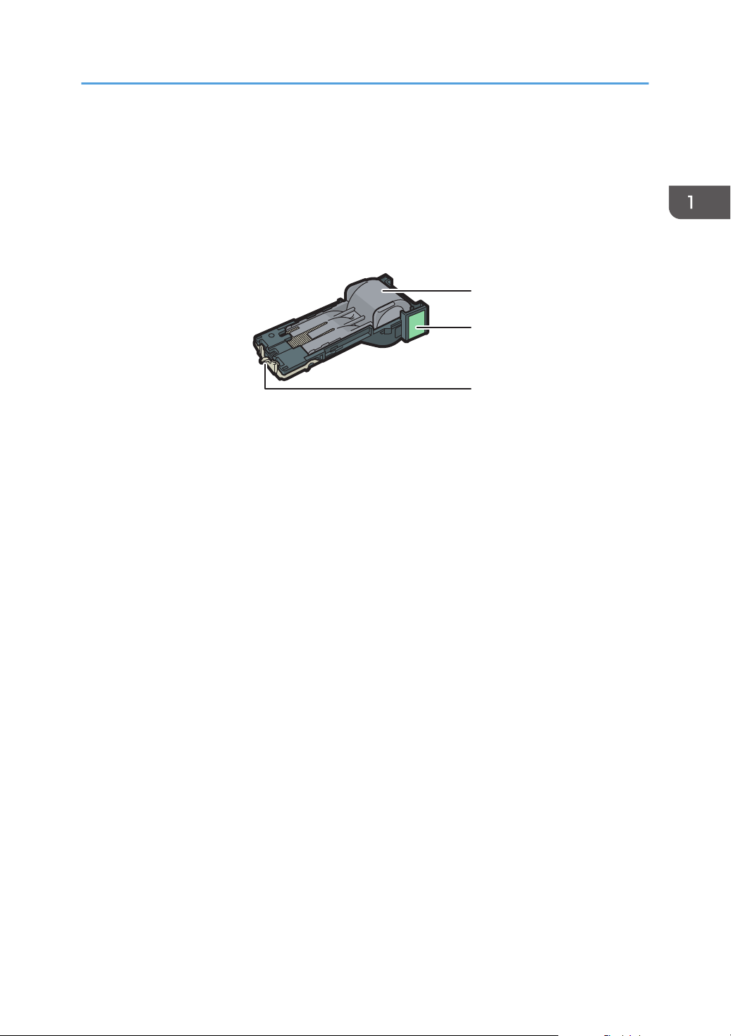
2. Staple unit
1
2
3
DVL426
3. Stapling slot
4. Slide switch
5. LED (to indicate there are no more staples)
Staple cartridge
1. Staple holder
2. Staple cartridge
Guide to Names and Functions of Components
3. Faceplate
17
Page 20
DVL802
1. Getting Started
Connecting and Setting the Network
Setting Wired LAN
Connecting Ethernet Interface
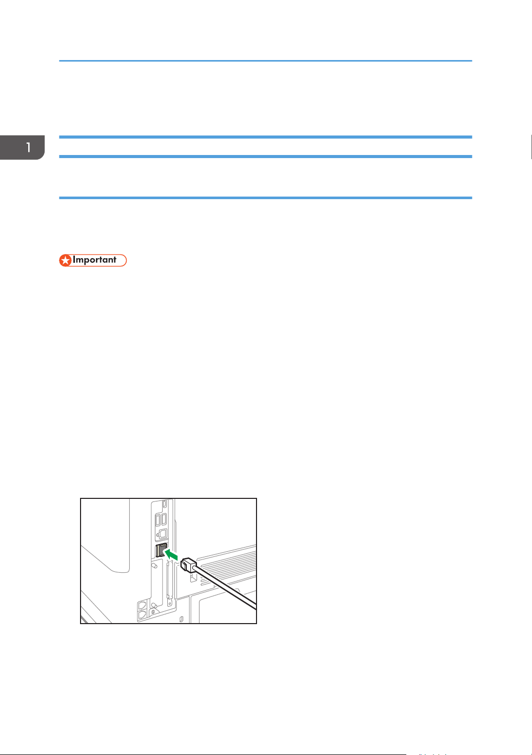
This section describes how to connect an Ethernet interface cable to the Ethernet port.
If you use an Ethernet interface cable that supports 1000BASE-T, set [Ethernet Speed] to [Auto Select:
Enable 1Gbps] in [Interface Settings] in [System Settings].
• Use the following Ethernet cables.
• When using 100BASE-TX/10BASE-T:
Unshielded Twisted Pair Cable (UTP) or Shielded Twisted Pair Cable (STP) and Category type
5 or more
• When using 1000BASE-T:
Unshielded Twisted Pair Cable (UTP) or Shielded Twisted Pair Cable (STP) and Category type
5e or more
• When you use IPv6, set [Effective Protocol] to [Active] in [Interface Settings] in [System Settings].
IPv6 is inactive as a factory default. When you enable IPv6, a link-local address is automatically
set.
• To use IPv6, consult your network administrator.
1. Make sure the main power is switched off.
2. Connect the Ethernet interface cable to the Ethernet port.
3. Connect the other end of the Ethernet interface cable to a network connection device such
as a hub.
18
Page 21
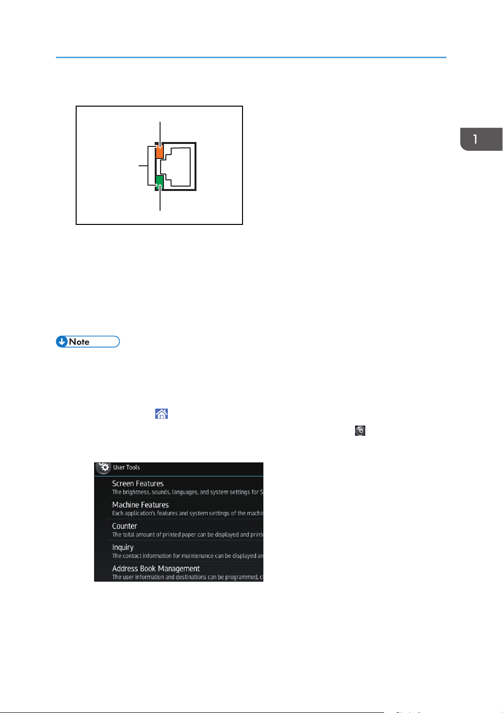
4. Turn on the main power switch of the machine.
3
2
1
DRS703
1. Indicator (orange)
When 100BASE-TX is operating, the LED is lit orange.
2. Indicator (green)
When 10BASE-T is operating, the LED is lit green.
3. Indicators (both orange and green)
When 1000BASE-T is operating, both LEDs are lit.
Connecting and Setting the Network
• When Energy Saver mode is enabled, the LEDs may not light up.
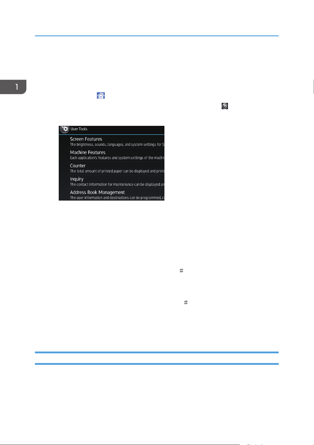
Obtaining an IP address automatically (IPv4 DHCP)
The machine is set to obtain IP addresses automatically as a factory default.
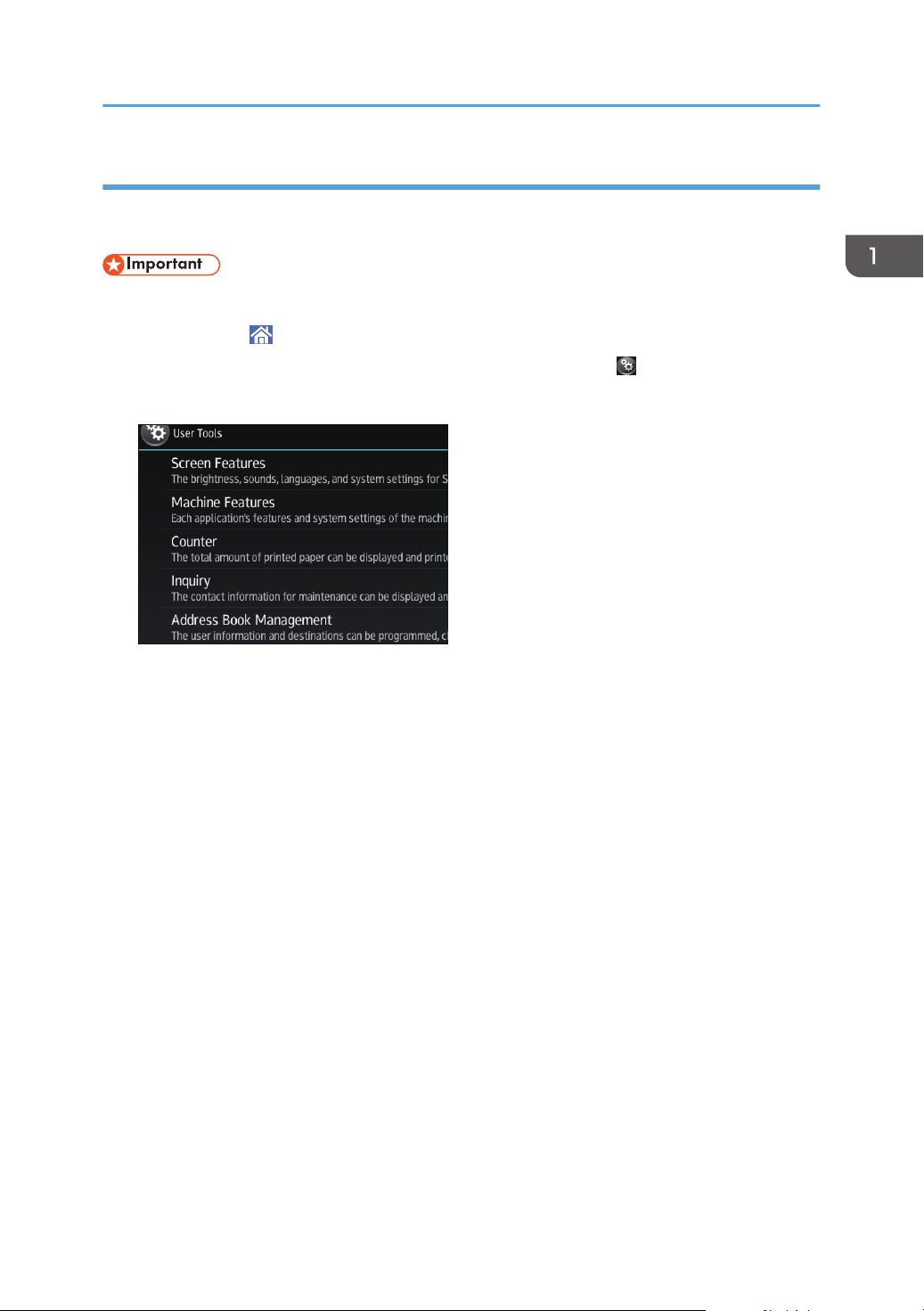
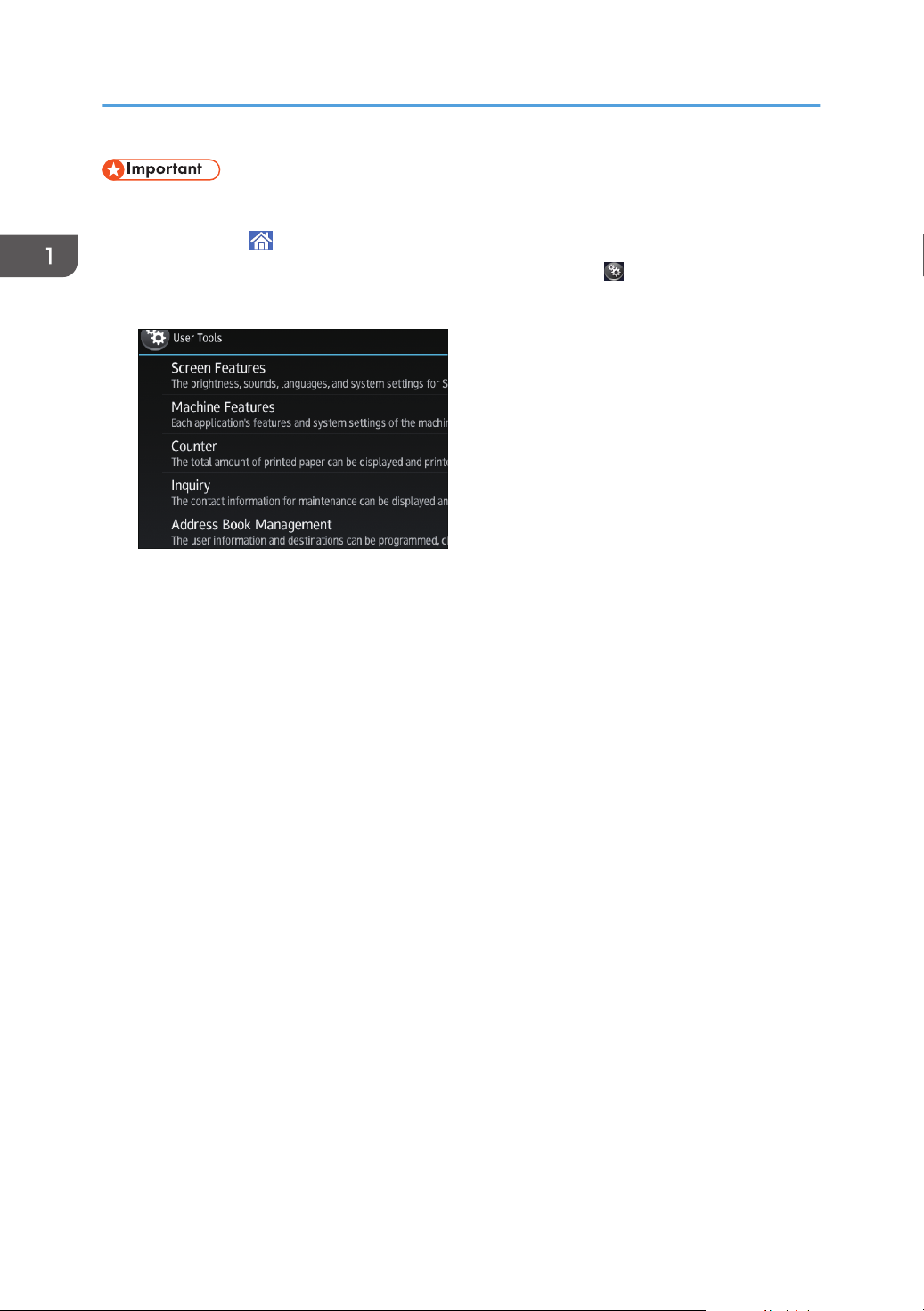
1. Press [Home] ( ) at the bottom of the screen in the center.
2. Flick the screen to the left, and then press the [User Tools] icon ( ).
3. Press [Machine Features].
4. Press [System Settings].
5. Press [Interface Settings] tab.
6. Press [Network].
7. Press [Machine IPv4 Address].
19
Page 22
1. Getting Started
8. Press [Auto-Obtain (DHCP)].
9. Press [OK].
Specifying an IP address (IPv4)
1. Press [Home] ( ) at the bottom of the screen in the center.
2. Flick the screen to the left, and then press the [User Tools] icon ( ).
3. Press [Machine Features].
4. Press [System Settings].
5. Press [Interface Settings] tab.
6. Press [Network].
7. Press [Machine IPv4 Address].
8. Press [Specify].
9. Press [Change] next to [Machine IPv4 Address], and then input the IP address.
When you complete entering the IP address, press [ ].
10. Press [OK].
11. Press [Change] next to [Subnet Mask], and then enter the subnet mask.
When you complete entering the subnet mask, press [ ].
12. Press [OK].
13. Press [IPv4 Gateway Address], and then enter the gateway address.
14. Press [OK].
Setting Wireless LAN
Wireless LAN connection is available when you install the optional Wireless LAN interface board.
See page 47 "Installing the Wireless LAN interface board" for how to install the Wireless LAN
interface board.
20
Page 23
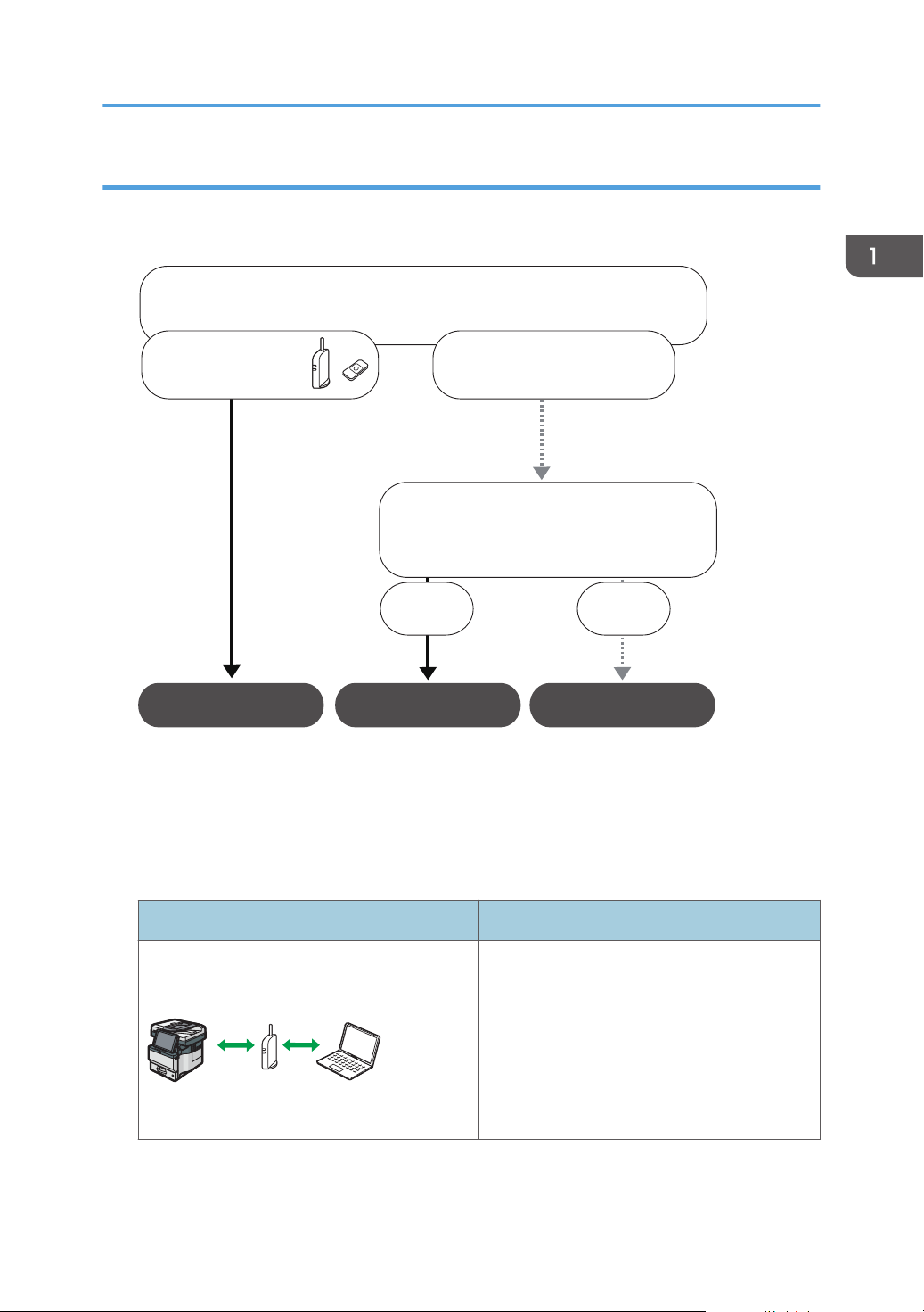
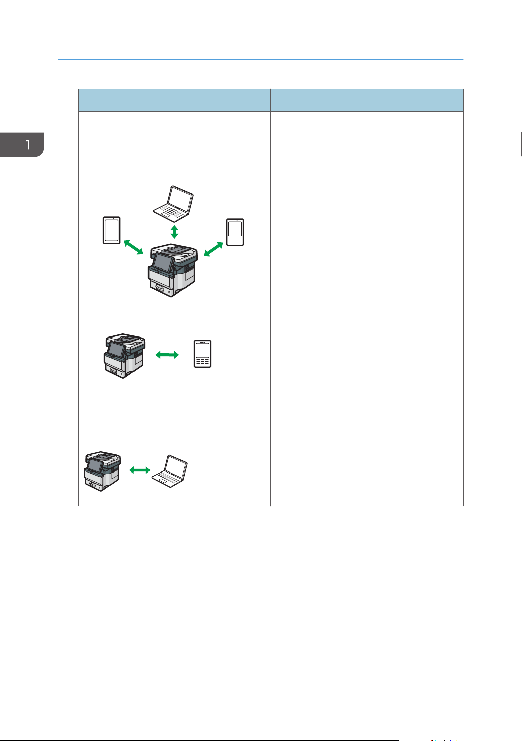
Selecting the communication mode for the Wireless LAN
DVL258
Which wireless LAN environment are you using?
Infrastructure
Wireless Direct Mode
Wireless Direct
Group Owner Mode
A wireless LAN
router is being used.
A wireless LAN router
is not being used.
Do you know how to specify the SSID*
or the password for connecting your
device to a network?
1
Yes No
DVL259
Select the communication mode according to your environment.
How to select the mode
Connecting and Setting the Network
*1
You can also connect via Ad hoc mode. For detailed information, see the explanation for each
mode.
About the modes
Infrastructure Mode
SSID is an identifier to distinguish Wireless LAN networks. It is also called a "Network name" or "Access
point name".
Mode Description
In infrastructure mode, you can connect
several devices and the machine via a wireless
LAN router.
You can also print data on a network, such as
a website, even when a device is connected.
The machine's communication mode is set to
infrastructure mode as a factory default.
21
Page 24
DVL260
DVK542
DVL261
1. Getting Started
Wireless Direct Mode
• Wireless Direct Group Owner Mode
• Wireless Direct
Mode Description
In Wireless Direct Mode, you can connect the
machine and a device without using a wireless
LAN router.
There are two types of connection methods in
Wireless Direct mode.
• Wireless Direct Group Owner Mode
You can connect several devices, including
devices that are not compliant with Wi-Fi
Direct. You need to enter the SSID and
password of the machine on the device you
want to connect.
• Wireless Direct
You can connect the machine and a device
directly to each other.
Select the machine from the device you want to
connect.
Only devices that are Android 4.0 or later and
support Wi-Fi Direct can be connected.
You cannot print data on a network, such as a
website, when a device is connected.
Ad-hoc Mode
You need to set the ad-hoc channel and other
settings, on the device you are connecting.
You cannot select WPA2 as the security
method. You cannot print data on a network,
such as a website, when a device is connected.
Procedure for the settings
For Ad hoc Mode, see page 23 "Connecting in Ad hoc Mode".
For Infrastructure Mode, see page 24 "Connecting in Infrastructure Mode".
For Direct Connection Mode, see page 26 "Connecting in Direct Connection Mode".
For Direct Connection Group Owner Mode, see page 27 "Connecting in Direct Connection
Group Owner Mode".
22
Page 25
Connecting and Setting the Network
Connecting in Ad hoc Mode
In Ad hoc mode, you can specify an SSID to the machine, and connect your computer directly to the
machine via a wireless LAN.
• The Wireless LAN interface board must be installed to use Ad hoc mode.
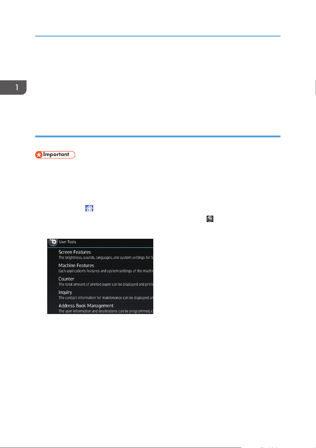
1. Press [Home] (
) at the bottom of the screen in the center.
2. Flick the screen to the left, and then press the [User Tools] icon ( ).
3. Press [Machine Features].
4. Press [System Settings].
5. Press [Interface Settings] tab.
6. Press [Network].
7. Press [LAN Type].
8. Press [Wireless LAN].
9. Press [Wireless LAN].
10. Press [Communication Mode], and then press [802.11 Ad-hoc Mode].
11. Press [OK].
12. Press [SSID Setting].
13. Press [Enter SSID] and enter SSID, and then press [OK].
14. Press [OK].
15. Press [Ad-hoc Channel], and then press the channel to use.
16. Press [OK].
17. Press [Security Method].
18. Press [WEP].
To not use security setting, select [No].
19. Press [Enter] in [WEP (Encryption) key].
23
Page 26
1. Getting Started
20. Enter WEP key, and then press [OK].
21. Press [OK].
The settings are complete.
You can connect the device in Ad hoc mode by specifying the SSID, channel, and security method that
are specified for the machine.
See the instructions supplied with the device for how to connect it in ad hoc mode.
Connecting in Infrastructure Mode
Use infrastructure mode to connect the machine to an access point.
• The Wireless LAN interface board must be installed to use Infrastructure mode.
• When you use IPv6, set Effective Protocol to Active in Interface Settings in System Settings. IPv6 is
inactive as a factory default. When you enable IPv6, a link-local address is automatically set.
• To use IPv6, consult your network administrator.
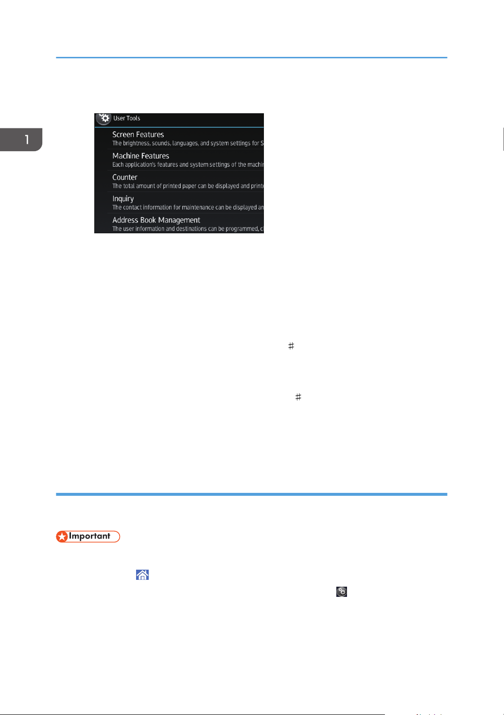
1. Press [Home] ( ) at the bottom of the screen in the center.
2. Flick the screen to the left, and then press the User Tools icon ( ).
3. Press [Machine Features].
4. Press [System Settings].
5. Press [Interface Settings] tab.
6. Press [Network].
7. Press [LAN Type].
8. Press [Wireless LAN].
9. Press [Wireless LAN].
10. Press [Communication Mode], and then press [Infrastructure Mode].
11. Press [OK].
24
Page 27

Connecting and Setting the Network
12. Press [SSID Setting].
13. Press [Enter SSID] and enter the SSID for the access point you want to connect to, and
then press [OK].
14. Press [OK].
15. Press [Security Method].
16. Enter the security method that is specified for the access point you want to connect to.
Press [WEP] or [WPA2], and then press [Enter] on the screen to enter your password.
If you do not use security setting, select [No].
17. Press [OK].
The settings are complete.
To check the connection status, press [Wireless LAN Signal] in [Wireless LAN] in [Interface Settings] in
[System Settings] and confirm the signal status.
Obtaining an IP address automatically (IPv4 DHCP)
The machine is set to obtain IP addresses automatically as a factory default.
1. Press [Home] ( ) at the bottom of the screen in the center.
2. Flick the screen to the left, and then press the [User Tools] icon (
3. Press [Machine Features].
4. Press [System Settings].
5. Press [Interface Settings] tab.
6. Press [Network].
7. Press [Machine IPv4 Address].
8. Press [Auto-Obtain (DHCP)].
9. Press [OK].
Specifying an IP address (IPv4)
).
1. Press [Home] ( ) at the bottom of the screen in the center.
2. Flick the screen to the left, and then press the [User Tools] icon ( ).
25
Page 28
1. Getting Started
3. Press [Machine Features].
4. Press [System Settings].
5. Press [Interface Settings] tab.
6. Press [Network].
7. Press [Machine IPv4 Address].
8. Press [Specify].
9. Press [Change] next to [Machine IPv4 Address], and then input the IP address.
When you complete entering the IP address, press [ ].
10. Press [OK].
11. Press [Change] next to [Subnet mask], and then enter the subnet mask.
When you complete entering the subnet mask, press [ ].
12. Press [OK].
13. Press [IPv4 Gateway Address], and then enter the gateway address.
14. Press [OK].
Connecting in Direct Connection Mode
To connect another device and the machine directly using the wireless direct function, use the Wireless
Direct mode.
• The Wireless LAN interface board must be installed to use Wireless Direct mode.
1. Press [Home] ( ) at the bottom of the screen in the center.
2. Flick the screen to the left, and then press the [User Tools] icon ( ).
26
Page 29

3. Press [Machine Features].
4. Press [System Settings].
5. Press [Interface Settings] tab.
6. Press [Network].
7. Press [LAN Type].
8. Press [Wireless LAN].
9. Press [Wireless LAN].
Connecting and Setting the Network
10. Press [Communication Mode], and then press [Direct Connection Mode].
11. Press [OK].
12. Press [Direct Connection].
13. Press [Active/Inactive] and press [Active].
14. Press [OK].
15. Press [Direct Connection Settings].
16. Check [Device Name] and [Connection Password], and then press [OK].
17. Press [Wireless LAN].
18. Press [Wireless LAN: Easy Setup/Direct Connection].
19. Press [Push Button].
20. Press [Connect].
The settings are complete.
Operate the push buttons on the device that you want to connect.
See the instructions supplied for the device for how to connect it in Wireless Direct mode.
Connecting in Direct Connection Group Owner Mode
To connect to multiple wireless direct-compliant devices by using the machine as a simple access point,
use the Direct Connection Group Owner mode. Up to nine devices can be connected. Non-wireless
direct-compliant devices can be connected too.
27
Page 30
1. Getting Started
• The Wireless LAN interface board must be installed to use Wireless Direct Group Owner mode.
1. Press [Home] ( ) at the bottom of the screen in the center.
2. Flick the screen to the left, and then press the User Tools icon ( ).
3. Press [Machine Features].
4. Press [System Settings].
5. Press [Interface Settings] tab.
6. Press [Network].
7. Press [LAN Type].
8. Press [Wireless LAN].
9. Press [Wireless LAN].
10. Press [Communication Mode], and then press [Direct Connection: Group Owner Mode].
11. Press [OK].
12. Press [Direct Connection].
13. Press [Active/Inactive] and press [Active].
14. Press [OK].
15. Press [Direct Connection Settings].
16. Check [Device Name] and [Connection Password], and then press [OK].
17. Press [Wireless LAN].
18. Press [Wireless LAN: Easy Setup/Direct Connection].
19. Press [Push Button].
20. Press [Connect].
The settings are complete.
Operate the push buttons on the device that you want to connect.
See the instructions supplied for the device for how to connect it by Wireless Direct mode.
28
Page 31

Connecting and Setting the Network
• If you specify the SSID and security method in [Wireless LAN] of [Interface Settings] under [System
Settings] while the machine is set to Wireless Direct Group Owner mode, the Non-Wireless Directcompliant devices can access to the machine by specifying the SSID and the security method of the
machine.
29
Page 32

DVL804
1. Getting Started
Connecting the USB Interface
Connecting to the USB (Type B) Interface
This section describes how to connect a USB 2.0 (Type B) interface cable to the USB 2.0 port on the
machine.
This machine does not come with a USB interface cable. Make sure you purchase the appropriate cable
for the machine (connector shape) and your computer.
Use a five meter (197 inch) or shorter cable which supports USB2.0 (Type B) interface.
1. Connect a USB2.0 (Type B) interface cable to the USB2.0 port.
Connecting a Device to the Machine's USB Host Interface
This section explains how to connect a device to the machine's USB host interface.
This machine does not come with a USB interface cable. Make sure you purchase the appropriate cable
for the machine (connector shape) and the device.
Use a five meter (197 inch) or shorter cable which supports USB Host Interface.
• Connect any of the following devices to the USB 2.0 interface: Digital camera, USB keyboards,
and IC card readers. Connecting other devices may cause a malfunction.
1. Connect one end of the USB interface device to the machine's USB host interface.
If you are using a USB interface cable, connect the other end of it to a device such as card
authentication one.
30
Page 33

DVL805
Connecting the USB Interface
31
Page 34

DVL807
2
1
1. Getting Started
Connecting the Machine to a Telephone Line and Telephone/Handset
Connecting the Telephone Line (mainly Europe and Asia)
To connect the machine to a telephone line, use a snap-in modular type connector.
• Make sure the connector is the correct type before you start.
• Connect the public switched telephone network (PSTN) to Line. Connecting lines other than PSTN
to this machine may cause it to malfunction.
32
1. LINE (G3 interface unit connector)
Connect a telephone line.
If you connect a modular cable to the G3 interface unit connector, make two loops 1.5 cm (0.6 inch) (1) from
the end of the modular cable (connection side to the machine) and attach the included ferrite core to the loops
as shown.
Page 35

1
CVC014
Connecting the Machine to a Telephone Line and Telephone/Handset
2. TEL (External telephone connector)
Connect the optional handset or an external telephone.
• If a cap has been inserted in the "TEL" connector, remove it before starting to use this connector.
Connecting the Telephone Line (mainly North America)
To connect the machine to a telephone line, use a snap-in modular type connector.
• A telephone line cable with a ferrite core must be used for RF interference suppression.
• Make sure the connector is the correct type before you start.
• Connect the public switched telephone network (PSTN) to Line. Connecting lines other than PSTN
to this machine may cause it to malfunction.
33
Page 36

DVL807
2
1
DLN707
1. Getting Started
1. G3 interface unit connector
Connect a telephone line.
2. External telephone connector
Connect the optional handset or an external telephone.
• If a cap has been inserted in the "TEL" connector, remove it before starting to use this connector.
• Use the supplied modular cable with a ferrite core. Connect the end of the cable with the ferrite
core to the machine.
Selecting the Line Type
Select the line type to which the machine is connected. There are two types: tone and pulse dial.
34
Page 37

Select the line type using Administrator Tools.
• This function is not available in some regions.
Connecting the Machine to a Telephone Line and Telephone/Handset
35
Page 38

1. Getting Started
Settings Needed for Each Function
The requirements of [Interface Settings] menu items under [System Settings] vary depending on the
function or interface environment that you are using. See Network Settings Requirements List and specify
the items necessary for the following functions.
• Printer/LAN-Fax
• Internet Fax
• E-mail Function
• Folder Function
• WSD Scanner
• Network TWAIN Scanner
• Document Server
• These settings should be made by the administrator, or with the advice of the administrator.
• For details about fax settings, see Fax.
• For details about scanner settings, see Scan.
36
Page 39

2
3
DVL281
1
Guide to Functions of the Machine's External Options
(mainly Europe and Asia)
Guide to Functions of the Machine's External Options (mainly Europe and Asia)
1. Staple Unit
You can attach the staple unit to stapling the output paper.
2. Lower paper trays
You can attach up to three lower paper trays.
There are two types of trays, each holding up to 250 or 500 sheets of paper.
These trays can be used in any combination.
Customer engineer attaches the paper tray depending on the number of the tray. Contact your service
representative. For details, see "Attaching the Paper Feed Unit", Setup.
3. Caster Table
A table with casters to place this machine.
37
Page 40

2
3
4
DVL477
1
1. Getting Started
Guide to Functions of the Machine's External Options (mainly North America)
1. Staple Unit
You can attach the staple unit to stapling the output paper.
2. Lower paper trays
You can attach up to three lower paper trays.
There are two types of trays, each holding up to 250 or 500 sheets of paper.
These trays can be used in any combination.
A customer engineer may be required to install this, depending on the number of levels being installed.
Contact your authorized service representative. For details, see "Attaching the Paper Feed Unit", Setup.
3. Caster Table
A table with casters to place this machine.
4. Handset
Used as a receiver.
Allows you to use the On Hook Dial and Manual Dial functions. It also allows you to use the machine as a
telephone.
38
Page 41

Order of Option Installation
Order of Option Installation
When installing multiple options, the following order is recommended:
1. Attach the Lower paper tray (250 sheets) and the Lower paper tray (500 sheets).
You can attach up to three paper feed units by any combination.
2. Attach the offline stapler.
3. Attach the Handset.
4. Install the interface board.
Install in the slot of the controller board.
Only one interface board can be installed.
5. Insert SD card.
Insert in the SD card slot of the controller board.
There are two slots for SD cards.
Each slot supports different types of SD cards.
If you want to use two or more SD cards that can be inserted in the same slot, contact your sales or
service representative.
39
Page 42

DVL102
1. Getting Started
Attaching the Paper Feed Unit
• It is dangerous to handle the power cord plug with wet hands. Doing so could result in electric
shock.
• The machine weighs approximately 30 kg (67 lb.).
• When moving the machine, use the inset grips on both sides, and lift slowly in pairs. The machine
will break or cause injury if dropped.
• Lifting the paper feed unit carelessly or dropping may cause injury.
• Unplug the power cord from the wall outlet before you move the machine. While moving the
machine, take care that the power cord is not damaged under the machine. Failing to take these
precautions could result in fire or electric shock.
• Do not place the machine directly on the floor.
• When attaching multiple options, attach the paper feed unit first.
• To attach two paper feed units at the same time, first stack them one upon the other, and then
attach them as a single unit.
• Before turning on the power, remove the packaging material from the paper feed unit.
1. Check the contents of the package.
2. Turn the machine off and unplug the power cord.
3. Remove the packaging from the paper feed unit.
4. Lift the machine using the inset grips on both sides of the machine.
40
Page 43

DVL103
Attaching the Paper Feed Unit
When moving the machine, do not hold on the following parts as doing so could cause a
malfunction:
• The handle onto the standard paper feed tray
• The underside of the bypass tray
5. There are three upright pins on the optional paper feed unit. Align them with the holes on
the underside of the machine, and then carefully lower the machine.
6. Plug in the power cord, and then turn on the machine.
7. Print the configuration page to confirm that the unit was attached correctly.
The number of tray that you can install
Use on table: printer
and three optional
paper feed units
Person who install
Use on table: printer and one or two optional
paper feed units
*1
41
Page 44

1. Getting Started
Person who install
Use on table: printer and one or two optional
paper feed units
User
Customer engineer
*1
A caster table is required to install three paper feed units on a machine.
Use on table: printer
and three optional
paper feed units
*1
42
Page 45

DVK536
DVL429
1
2
Installing the Offline Stapler
Installing the Offline Stapler
This section describes how to install and use the staple unit.
• Do not remove the offline stapler after pressing it to fix it to the release paper.
• Do not press or hit the offline stapler strongly. Doing so may damage it.
• Do not hold the offline stapler when you move the machine.
1. Turn off the machine's power, and then pull the power plug out of the wall outlet.
2. By using a coin, open the cover on the right side of the machine.
3. Take the offline stapler out of the box.
The offline stapler consists of a staple unit and a staple unit cradle. These parts are separate in the
box.
1. Staple unit
2. Staple unit cradle
43
Page 46

DVL431
DVL432
DVL151
1. Getting Started
4. Fold outside the parts of the release paper that are not stuck to the double-sided tapes on
the back of the staple unit cradle.
The adhesion of the release paper is strong, so it cannot be detached once it is affixed. Do not affix
the release paper until Step 7.
5. Align the hole on the staple unit cradle to the bump that is on the right side of the
machine, and then insert the screw into the screw hole.
If the right side of the machine is dirty, clean the surface before mounting the staple unit cradle on
the machine.
44
6. Align the lines of both the machine and the staple unit cradle as shown in the illustration,
and then turn the screw until it stops.
Page 47

DVL433
DVL434
DVL435
Installing the Offline Stapler
7. Pull out the pieces of release paper that were folded outside, and then press the staple
unit cradle towards the machine.
Support the staple unit cradle with a hand so that it does not move when pulling out the release
paper. Do not press the staple unit forcibly. The release paper may tear. Pull the release paper to
the sides slowly.
After removing the release paper, press forcibly on the staple unit cradle to fasten it to the machine.
8. Insert the staple unit into the staple unit cradle.
Push the staple unit firmly into the back.
45
Page 48

DVL436
1. Getting Started
9. Turn the machine's power on.
The power of the offline stapler also turns on.
46
Page 49

DVL370
DVL371
Installing the Wireless LAN interface board
Installing the Wireless LAN interface board
• Before beginning work, ground yourself by touching something metal to discharge any static
electricity. Static electricity can damage the interface units.
• Do not subject the Wireless LAN interface board to physical shocks.
1. Check the contents of the package.
2. Turn the machine off and unplug the power cord.
3. Loosen the two screws and remove the slot cover.
The removed cover will not be reused.
4. Fully insert the interface board.
Confirm that the interface board is firmly connected to the controller board.
5. Tighten the two screws to secure the interface board.
6. Plug in the power cord, and then turn on the machine.
7. Print the configuration page to confirm that the board was attached correctly.
After installing the Wireless Interface board, see page 20 "Setting Wireless LAN" to specify the
wireless LAN settings.
47
Page 50

DVL370
DVL373
1. Getting Started
Installing the IEEE 1284 interface board
• Before beginning work, ground yourself by touching something metal to discharge any static
electricity. Static electricity can damage the interface units.
• Do not subject the IEEE 1284 interface board to physical shocks.
1. Check the contents of the package.
2. Turn the machine off and unplug the power cord.
3. Loosen the two screws and remove the slot cover.
The removed cover will not be reused.
4. Fully insert the IEEE 1284 interface board.
Confirm that the IEEE 1284 interface board is firmly connected to the controller board.
5. Tighten the two screws to secure the interface board.
6. Plug in the power cord, and then turn on the machine.
7. Print the configuration page to confirm that the board was attached correctly.
48
Page 51

DVL806
Installing the IEEE 1284 interface board
Connecting to the IEEE 1284 Interface
This section describes how to connect an IEEE 1284 interface cable to the optional IEEE 1284 interface
board.
This machine does not come with an IEEE 1284 interface cable. Make sure you purchase the
appropriate cable for the machine (connector shape) and your computer.
Use a five meter (197 inch) or shorter IEEE 1284 compatible cable whose performance is guaranteed
on the host computer.
1. Make sure the main power switch on the machine is off.
2. Turn off the main power switch of the host computer.
3. Connect an IEEE 1284 interface cable to the IEEE 1284 port.
You might have to use a conversion adapter to connect the cable to the interface. For details about
acquiring a conversion adapter, consult your sales or service representative.
4. Connect the other end of the cable into the interface connector on the host computer.
Before connecting the cable to the computer, check the shape of the connector. Connect the cable
firmly.
5. Turn on the main power switch of the machine.
6. Turn on the host computer.
When using Windows 7/8.1/10 and Windows Server 2008/2008 R2/2012/2012
R2/2016, a printer driver installation screen might appear when the computer is turned on. If this
happens, click [Cancel] on the screen.
49
Page 52

DVL370
DVL377
1. Getting Started
Installing the Extended USB board
• Before beginning work, ground yourself by touching something metal to discharge any static
electricity. Static electricity can damage the interface units.
• Do not subject the Extended USB board to physical shocks.
1. Check the contents of the package.
2. Turn the machine off and unplug the power cord.
3. Loosen the two screws and remove the slot cover.
The removed cover will not be reused.
4. Fully insert the interface board.
Check that the interface board is firmly connected to the controller board.
5. Tighten the two screws to secure the interface board.
6. Plug in the power cord, and then turn on the machine.
7. Print the configuration page to confirm that the board was attached correctly.
See page 30 "Connecting the USB Interface" to connect with USB interface.
50
Page 53

DVL370
DVL375
Installing the USB device server
Installing the USB device server
• Before beginning work, ground yourself by touching something metal to discharge any static
electricity. Static electricity can damage the interface units.
• Do not subject the USB device server to physical shocks.
The optional USB device server is an interface board that adds an Ethernet port to the machine.
With this option installed, two Ethernet cables can be connected at the same time using the standard port
on the machine and an additional port on the USB device server. You can assign different IP addresses
to each port, so the machine can print jobs from different network segments.
Procedure for installing the USB device server
1. Check the contents of the package.
2. Turn the machine off and unplug the power cord.
3. Loosen the two screws and remove the slot cover.
The removed cover will not be reused.
4. Fully insert the interface board.
51
Page 54

1. Getting Started
Check that the interface board is firmly connected to the controller board.
5. Tighten the two screws to secure the interface board.
6. Connect the USB device server to the machine.
For details, see the Setup Guide provided with the USB device server.
Connecting to the Extra Ethernet Interface with the USB Device Server Option
This section describes how to connect an Ethernet interface cable to the Ethernet port of the optional USB
Device Server.
USB Device Server Option is an interface board for adding an extra Ethernet port. If you install USB
Device Server Option, you can connect two Ethernet cables simultaneously: one to the machine's
Ethernet port and one to the Ethernet port of USB Device Server Option. An IP address can be assigned
to each connection, and you can use one machine to print from different network segments.
Remove the cover of USB2.0 port on the machine and connect the port to the USB port of the USB
device server.
• A network interface cable with a ferrite core must be used for RF interference suppression.
• Use the following Ethernet cables.
• When using 100BASE-TX/10BASE-T:
Unshielded Twisted Pair Cable (UTP) or Shielded Twisted Pair Cable (STP) and Category type
5 or more
• When using 1000BASE-T:
Unshielded Twisted Pair Cable (UTP) or Shielded Twisted Pair Cable (STP) and Category type
5e or more
1. Make sure the main power switch is turned off.
52
Page 55

1
1
BZU010
DVL803
Installing the USB device server
2. Make a loop at a distance of a few centimeters (1) from each end of the Ethernet interface
cable, and then attach to each loop the ferrite core provided with the USB Device Server
Option.
3. Connect the Ethernet interface cable to the Ethernet port of the USB Device Server Option.
You can use either a straight or crossover Ethernet cable for connecting to the USB Device Server
Option.
4. Connect the other end of the Ethernet interface cable to a network connection device such
as a hub.
It may take several seconds for the machine to recognize the USB Device Server Option. If you
have disconnected the USB cable, connect the USB cable again.
53
Page 56

DYQ550
1
2
3
1. Getting Started
5. Turn on the main power switch of the machine.
1. Indicator (orange)
When 100BASE-TX is operating, the LED is lit orange.
2. Indicator (green)
When 10BASE-T is operating, the LED is lit green.
3. Indicators (both orange and green)
When 1000BASE-T is operating, both LEDs are lit.
Specifying an IP address for the USB Device Server
Specify the IP address for the USB device server manually.
You can share the machine among multiple networks by specifying an IP address of a segment different
from that of the machine.
The default network settings of the USB device server are as follows:
• DHCPv4: Disable
• IPv4 address: 192.168.100.100
• Subnet Mask: 255.255.255.0
• Default Gateway: 0.0.0.0
• Network PnP: Enable
• mDNS: Enable
• LAN Interface: Auto
• Primary WINS Server: 0.0.0.0
• Secondary WINS Server: 0.0.0.0
To change the IP address for the USB device server, access the setting screen for the machine using a
web browser. For details about the setting items, see the USB device server's Help.
54
Page 57

DDE015
Installing the USB device server
• To use the USB device server in an IPv6 environment, it is necessary to change the network settings
in an IPv4 environment first.
• The machine status does not appear on your computer because the USB device server does not
support bidirectional communication.
• You cannot set the IP address for the USB device server using the control panel of the machine.
• The default administrator password is not specified. It is recommended that you specify the
administrator password on the [Maintenance Information] screen by using up to seven
alphanumeric characters.
• If you forget the IP address of the USB device server or have changed it from its default, follow the
procedure below to initialize the USB device server settings:
1. Turn off the main power of the machine.
2. Press and hold the switch on the interface using a pointed tool such as a pen, and turn on the
machine.
3. Both the upper and lower LEDs of the Ethernet port light up. Be sure to check the upper LED
turns off and the lower LED lights up in yellow, and then release the switch.
• Confirm the IP address of your computer before starting setup. The default IP address for the USB
device server is "192.168.100.100", and the default subnet mask is "255.255.255.0". To
perform the initial setup of the USB device server, set the IP address for your computer to
"192.168.100.XXX" (set XXX to any number, other than 100, from 0 to 255), and the subnet mask
to "255.255.255.0". It is recommended to make a note of the current IP address before changing
it.
1. Enter "http://192.168.100.100/" in the address bar of the Web to access the setting
screen of the machine.
2. Click [Network Settings].
3. Enter "root" as the user name, and then click [OK].
55
Page 58

1. Getting Started
4. Specify the IP address, Subnet Mask, and Default Gateway.
When DHCP is enabled, the IP address can be obtained automatically from a network device with
the DHCP server function.
5. Configure the other settings as necessary, and then click [Submit].
6. Exit the web browser.
7. Disconnect the Ethernet interface cable from the computer used for setup, and then
connect the cable to a network device, such as a hub.
8. Set the IP address of the USB device server in the printer driver used for printing.
• The USB device server does not support "Quick Install" and installation using the
SmartDeviceMonitor for Client port. A port must be set independently when a printer driver is
installed.
• To print using Port 9100 or LPR, see Driver Installation Guide and make the following settings:
1. Specify the IP address for the USB device server using the "Add Standard TCP/IP Printer Port
Wizard".
2. Select "Custom" for the device type.
3. For Port 9100, select "Raw" as the protocol, and then specify "9100" for the port number. For
LPR, select "LPR" as the protocol, and then specify "lp" as the queue name.
• For IPP printing, see "Using the IPP port", Driver Installation Guide. To specify the URL of the
machine during the procedure for adding printers, enter "http://(IP address of the USB device
server) /ipp/lp".
56
Page 59

DVL370
DVL379
Installing the File Format Converter
Installing the File Format Converter
• Before beginning work, ground yourself by touching something metal to discharge any static
electricity. Static electricity can damage the interface units.
• Do not subject the File Format Converter to physical shocks.
1. Check the contents of the package.
2. Turn the machine off and unplug the power cord.
3. Loosen the two screws and remove the slot cover.
The removed cover will not be reused.
4. Fully insert the file format converter.
Check that the file format converter is firmly connected to the controller board.
5. Tighten two screws to secure the file format converter.
6. Plug in the power cord, and then turn on the machine.
7. Print the configuration page to confirm that the board was attached correctly.
57
Page 60

DVL381
DVL382
1. Getting Started
Installing SD Card Options
• Keep SD cards out of reach of children. If a child swallows a SD card, consult a doctor
immediately.
• Do not subject the card to physical shocks.
1. Turn the machine off and unplug the power cord.
2. Loosen the screw and remove the SD card slot cover at an angle.
3. Insert the SD card into the slot until it clicks.
If you insert only one SD card, use the upper slot. If you insert two SD cards simultaneously, use
both slots. If you insert the optional VM card, use only the lower slot.
If you want to use three or more SD cards simultaneously, contact your service representative.
If you use a commercially available SD card for buck up the address book, insert the SD card to
lower slot.
58
Page 61

DVL383
Installing SD Card Options
4. Hook the SD card slot cover onto the opening, attach it flat against the controller board,
and then fasten it using the screw.
5. Plug in the power cord, and then turn on the machine.
6. Confirm that the SD card was installed correctly.
59
Page 62

DVL390
213
4
1. Getting Started
Installing the Handset (mainly North America)
Connecting the handset enables you to use the machine as a telephone and to easily switch the
reception mode when a telephone call arrives.
For details about switching the reception mode, see "Fax Reception Modes", Fax.
• Do not apply strong impact or force to the bracket, or it may be damaged. Maximum force
allowable is approx. 50N (approx. 5 kgf). (N = Newton, kgf = Kilogram force. 1 kgf = 9.8N.)
• When you fix the handset cradle to the handset bracket, do not screw it too tightly. Doing so may
damage the cradle or bracket.
• A ferrite core is attached to the handset cord to reduce noise. Do not remove the ferrite core.
Connecting the handset
1. Make sure you have all the following items.
1. Handset
2. Handset cradle
3. Screws (2)
4. Handset bracket
60
Page 63

DVL391
DVL392
1
2
DVL393
1
2
Installing the Handset
2. Remove the protective tape from the handset bracket.
3. Attach the bracket to the left side of the machine, as shown below.
(mainly North America)
4. Remove the inquiry card from the handset cradle.
The card can be easily removed by pushing it from the back of the handset.
61
Page 64

DVL394
DVL395
DVL396
1. Getting Started
5. Fix the handset cradle to the handset bracket by turning the screws with a coin.
6. Place the inquiry card back in the handset cradle.
7. Place the handset on the handset cradle, and connect the handset cord to the external
telephone connector.
Configuring the handset
Selecting a telephone line type for the handset
With a thin, pointed object, set the switch on the handset to the line type you are using
Push button phone: Push
62
Page 65

PUSH
10 20
DIAL
CHP106
H L OFF
CHP107
Installing the Handset
Dial phone: 10 (PPS)
Adjusting the handset bell volume
With a thin, pointed object, adjust the bell volume using the volume switch.
High : H
Low : L
No sound : OFF
(mainly North America)
63
Page 66

DVK532
1. Getting Started
Connecting the telephone
1. Connect the cord of the telephone to "TEL" connector.
64
Page 67

DCH009
21
4
5
6
6
7
3
Guide to the Names and Functions of the Machine's Control Panel
Guide to the Names and Functions of the
Machine's Control Panel
1. Display panel
This is a touch panel display that features icons, keys, shortcuts, and widgets that allow you to navigate the
screens of the various functions and applications and provide you with information about operation status and
other messages. See page 67 "How to Use the [Home] Screen" and page 73 "How to Use Each
Application".
2. Main power indicator
The main power indicator goes on when you turn on the main power switch. When the machine is in Sleep
mode, the main power indicator flashes slowly. In Fusing Unit Off mode, the main power indicator is lit.
3. Status indicator
Indicates the status of the system. Stays lit when an error occurs or the toner runs out.
4. Data In indicator (facsimile and printer mode)
Flashes when the machine is receiving print jobs or LAN-Fax documents from a computer. See Fax and Print.
5. Fax indicator
Indicates the status of the fax functions. Flashes during data transmission and reception. Stays lit when
receiving a fax via Confidential or Substitute Reception.
6. Media slots
Use to insert an SD card or a USB flash memory device. For details, see "Inserting/Removing an SD Card" or
"Inserting/Removing USB Flash Memory Device", For First-time Users.
7. Media access lamp
Lights up when an SD card is inserted in the media slot. Flashes when the SD card is being accessed.
65
Page 68

1. Getting Started
Changing the Display Language
You can change the language used on the display. English is set as default.
1. Press [Home] ( ) at the bottom of the screen in the center.
2. Flick the screen to the left, and then press the [Change Langs. Widget].
3. Select the language you want to display.
4. Press [OK].
• You can register display languages. For details about Select Switchable Languages, see "Screen
Features", Settings.
66
Page 69

DVL534
6
7
14
1 3 4 5
89101113
2
12
How to Use the [Home] Screen
How to Use the [Home] Screen
The [Home] screen is set as the default screen when the machine is turned on.
One icon is assigned to each function, and these icons are displayed on the [Home] screen. You can
add shortcuts to frequently used functions or Web pages to the [Home] screen. Also, you can register
widgets such as the Change Langs. Widget to it. The [Home] screen and the screen of each function may
differ depending on the optional units that are installed.
To display the [Home] screen, press [Home] ( ) at the bottom of the screen in the center.
• Do not apply strong impact or force to the screen, or it may be damaged. Maximum force
allowable is approx. 30N (approx. 3 kgf). (N = Newton, kgf = Kilogram force. 1 kgf = 9.8N.)
To switch between screens, flick your finger to the right or left on the screen.
1. Logged-in user icon
When user authentication is enabled, an icon is displayed that indicates that users are logged in.
Press the icon to show the names of the users that are currently logged in.
2. System message
Displays messages from the machine system and applications.
3. [Help]
Displays help for operating the machine.
4. [Login]/[Logout]
These keys are displayed when user authentication is enabled. When you press [Login], the authentication
screen appears. If you have been already logged in to the machine, [Logout] appears. To log out of the
machine, press [Logout].
For details about how to log in and out, see page 93 "Logging In the Machine".
5. [Energy Saver]
Press to switch to Sleep mode.
67
Page 70

1. Getting Started
For details about the modes, see "Saving Energy", For First-time Users.
6. Application list icon
Press to display the application list. You can create shortcuts to the applications on the [Home] screen.
To use an application displayed in the [WIDGET] tab and [PROGRAM] tab, create a shortcut for the
application on the [Home] screen. For details, see "Customizing the [Home] Screen", For First-time Users.
7. Icons to switch between screens
Press to switch between the five home screens. The icons appear at the bottom right and left of the screen, the
number of icons indicates the number of screens on each side of the current screen.
8. [Stop]
Press to stop a job in progress, such as copying, scanning, faxing, or printing.
9. [Menu]
Displays the menu screen of the application you are using. Depending on the application you are using, this
key may be disabled. You can also press this key in the [Home] screen to restore the [Home] screen's settings
to their defaults.
10. [Home]
Press to display the [Home] screen.
11. [Return]
Press this key to return to the previous screen while Screen Features are enabled or applications are used.
Depending on the application you are using, this key may be disabled. You can specify whether this key is
enabled or not in some applications. For details about the settings, see "Screen Features", Settings.
12. [Media Information]
Press to remove the inserted SD card or USB flash memory device from the media slot. For details, see
"Inserting/Removing an SD Card" or "Inserting/Removing USB Flash Memory Device", For First-time Users.
13. [Check Status]
Press to check the machine's system status, network setting, operational status of each function, and current
jobs. You can also display the job history and the machine's maintenance information.
Pressing [Change Settings] in the network status displays network setting menu and allows you to change
network setting.
14. Icon display area
Displays the function or application icons and widgets. Displayed icons differ between the five home screens.
For details about icons on each screen, see "Main Icons on the [Home] Screen", For First-time Users.
You can also add shortcuts and arrange icons using folders. For details, see "Customizing the [Home]
Screen", For First-time Users.
68
• You can change the [Home] screen's wallpaper. For details, see "Changing the [Home] Screen's
Wallpaper", For First-time Users.
• You can switch modes by pressing icons on the [Home] screen. You can also switch modes by
pressing the function keys. For details about the function keys, see "Changing Modes by Pressing
the Function Keys", For First-time Users.
Page 71

DNE103
How to Use the [Home] Screen
• You cannot switch modes in any of the following situations:
• While scanning an original using the fax or scanner function
• When accessing the following screens:
• Machine Features
• Counter
• Inquiry
• Address Book Management
• Tray Paper Settings
• Current Job / Job History
• During interrupt copying
• During On-hook dialing for fax transmission
• The [Home] screen is set as the default screen when the machine is turned on. You can change this
default setting under Function Priority. See "Screen Features", Settings.
Possible Operations on the Standard Application Screen
• Pinch-in
Place your thumb and forefinger on the screen, and then pinch the fingers together to zoom out the
screen. Double-tapping can also be effective for this operation.
• Pinch-out
Place your thumb and forefinger on the screen, and then spread the fingers apart to zoom in the
screen. Double-tapping can also be effective for this operation.
69
Page 72

DNE104
DNE102
DNE101
1. Getting Started
• Flick
Flick your finger to the right or left on the screen to switch between screens.
• Long tap
Place your finger on the screen and hold it there until the next screen appears. You can display the
menu screen of the application you are using.
• Drag
Slide your finger while pressing the screen. You can move an icon to where you want to place it on
the screen.
70
Page 73

DNE111
How to Use the [Home] Screen
Adding Shortcuts to the [Home] Screen
You can add shortcuts to the machine's functions.
You can display the icons for the machine's functions and the embedded software applications after you
delete them from the [Home] screen.
1. Press [Home] (
) at the bottom of the screen in the center.
2. Press .
3. Press the [Apps] tab to add a shortcut to an application other than the Classic
Applications. Press the [PROGRAM] tab to add a shortcut to one of the Classic
Applications.
4. Press and hold down the application icon to add a shortcut to an application other than
the Classic Applications. Press and hold down the [Classic Applications] icon to add a
shortcut to one of the Classic Applications.
The image of where the shortcut is to be placed on the [Home] screen is displayed.
5. Drag the icon to where you want to place it on the screen.
If you want to add a shortcut to the Classic Applications, proceed to Step 6.
6. Select the Classic Applications that you want to add from the list.
Adding Shortcuts to Bookmarks on the [Home] Screen
You can add shortcuts to bookmarks that have been registered in favorites in the Web Browser to the
[Home] screen.
1. Press [Home] ( ) at the bottom of the screen in the center.
2. Press .
3. Press the [PROGRAM] tab.
4. Press and hold down the [Bookmark] icon.
The image of where the shortcut is to be placed on the [Home] screen is displayed.
71
Page 74

1. Getting Started
5. Drag the icon to where you want to place it on the screen.
6. Select the bookmark you want to add from the bookmark list.
Adding Shortcuts to Programs to the [Home] Screen
You can add shortcuts to programs registered on Copier, Facsimile, Scanner mode, or quick
applications.
1. Display the function screen to which you want to register a program.
2. When you are using the standard applications or quick applications, press [Menu] ( ) at
the bottom of the screen in the center. When you are using the Classic Applications, press
[Recall/Program/Change Program] on the bottom left of the screen.
3. Register a program.
4. Press [Home] ( ) at the bottom of the screen in the center.
5. Press .
6. Press the [PROGRAM] tab.
7. To display a program registered to the standard applications or quick applications, hold
down the application icon. To display a program registered to the Classic Applications,
hold down the [Classic Applications] icon.
The image of where the shortcut is to be placed on the [Home] screen is displayed.
8. Drag the icon to where you want to place it on the screen.
9. Select the program you want to add from the list.
Adding Widgets to the [Home] Screen
You can add widgets to the [Home] screen to show the remaining amount of toner or change the display
language.
1. Press [Home] ( ) at the bottom of the screen in the center.
2. Press .
3. Press the [WIDGET] tab.
4. Press and hold down the widget icon you want to add.
The image of where the widget is to be placed on the [Home] screen is displayed.
5. Drag the icon to where you want to place it on the screen.
72
Page 75

DVL251
How to Use Each Application
How to Use Each Application
You can open the function screens by pressing icons such as [Copy], [Fax], or [Scanner] on the [Home]
screen.
Three kinds of screens ("Standard Application Screen", "Classic Application Screen", and "Quick
Application Screen") can be used by each function.
Standard Application Screen
Functions and settings that are used frequently are shown on the top screen. Flick the screen up or
down to select a setting item. When you select an item, the pull-down menu appears, or the setting
item pops up. For details about operations on this screen, see page 69 "Possible Operations on the
Standard Application Screen". For details about how to use the screen, see page 74 "[Copy]
(standard) Screen", page 76 "[Fax] (standard) Screen", and page 82 "[Scanner] (standard)
Screen".
Classic Application Screen
You can select advanced functions and detailed settings according to the functions and settings you
use frequently. For details about how to use this screen, see "How to Use Each Application", For
First-time Users. For details about keys that appear on the screen of each Classic Application, see
"Keys that Appear on the Initial Settings Screen and Screens of Each Classic Application", For Firsttime Users.
Quick Application Screen
You can easily set the basic operations such as duplex copying, sending scanned documents by email or other operations. For details about how to use this screen, see "How to Use Each
Application", For First-time Users.
Functions usable on each screen
Screen Functions usable
Standard Application Screen
• Copier
• Fax
• Scanner
73
Page 76

DVL252
DVL253
DVL268
6
23 4
5
1
1. Getting Started
Screen Functions usable
Classic Application Screen
• Copier
• Fax
• Scanner
• Printer
• Document Server
Quick Application Screen
• Copier
• Fax
• Scanner
• [Copier (Classic)] icon, [Fax (Classic)] icon, [Scanner (Classic)] icon, and [Printer (Classic)] icon
are displayed in the Application list. For details about how to register them to the [Home] screen,
see "Customizing the [Home] Screen", For First-time Users.
[Copy] (standard) Screen
You can switch the two screens described in this section by flicking the screen up or down.
The items on the screen vary depending on the machine’s settings.
74
Page 77

No. Icon Description
DVL541
8 97
10
11
You can adjust the density of the overall original in nine steps.
1
Specify the density by touching the icon and dragging it right or left.
You can reduce or enlarge images.
2
You can specify the paper tray containing the paper you want to copy
3
to.
You can specify the numbers of copies to be made.
4
Press a number to enter the number of copies using the keyboard. You
can also specify the number of copies by pressing [ ] or [ ].
Preview prints change according to the settings you make.
5
How to Use Each Application
You can combine two 1-sided originals or one 2-sided original to one
6
side of a sheet. The machine selects a reproduction ratio automatically
and copies the originals onto a single sheet of copy paper.
No. Icon Description
You can sort copies as a set in sequential order and stack copies of each
7
page in a multi-page original.
75
Page 78

DVL542
531 4
14
6
8
2
1112
13
7
9
10
1. Getting Started
No. Icon Description
You can specify the size of the original when copying custom size
8
originals.
You can select an original type that is suitable for your originals.
9
You can divide an original that has many pages and scan it in smaller
10
batches while copying it as a single document. To do this, place several
pages of the original in the ADF.
You can find other settings.
11
[Fax] (standard) Screen
No. Icon Description
1
You can switch between items in type of
transmission.
76
Page 79

How to Use Each Application
No. Icon Description
The specified destination is shown here.
By tapping the destination, you can register it to
2
the Address Book or remove it from the
destinations.
By flicking up and down, you can confirm the
selected destinations.
You can perform the following operations
related to Fax Reception:
• Check Stored Reception Files
• Operate Personal Box
3
• Print ID Required Print Files
• Manual Reception
• Print Memory Lock
• Check Reception File Settings
This function allows you to dial while listening to
the dial tone from the internal speaker with the
handset of the machine or external telephone
on-hook.
The total number of the selected destinations
appears.
4
Press to display a screen to confirm destinations.
In the screen to confirm destinations, you can do
the following:
• Register destinations to the Address Book
• Edit destinations
• Remove destinations from the destination list
You can perform the following operations
related to Job Status:
• Confirm Transmission Standby Files
5
• Check Transmission Results
• Check Reception Results
• Print Journals
77
Page 80

1. Getting Started
No. Icon Description
Press to clear your current settings.
6
Press to display the preview screen after
7
scanning originals.
8
9
10
11
12
13
You can check the settings in Settings.
Press to open the settings screen. For details, see
page 79 "[Settings] screen".
Press to scan originals and start sending.
Press to switch the section of the Address Book.
Shows the destinations in the Address Book.
The sections of the Address Book.
78
Page 81

No. Icon Description
DVL543
1 2 3
4 5 6
Press to add a destination.
Destinations can be added as follows:
• Input destinations manually
• Select from the transmission history
• Specify a registration number from the
14
Address Book
• Search for a destination in the Address
Book or on the LDAP server
• Press to display the Remaining Memory
Information
You can also add a destinations to the Address
Book.
[Settings] screen
How to Use Each Application
You can switch the three screens described in this section by flicking the screen up or down.
The items on the screen vary depending on the machine’s settings.
No. Icon Description
You can switch to immediate transmission mode.
1
79
Page 82

DVL544
11
10
7
8
9
1. Getting Started
No. Icon Description
You can select an original type that is suitable for
2
your originals.
Press to select the resolution according to the
3
size of the text on your original.
Press to specify the density to scan the original.
4
You can also specify the density by touching the
icon and dragging it right or left.
Press to select the scanning size of the original.
5
Press to select the sides of the original.
6
80
No. Icon Description
Press to select the orientation of the original.
7
Press to specify the sender.
8
Page 83

DVL545
15
16 17
12 13
14
How to Use Each Application
No. Icon Description
You can specify settings to automatically send
9
files directly at a specified time.
Specify the Internet Fax subject.
10
Specify the Internet Fax Text.
11
No. Icon Description
You can select a standard message to be
12
printed.
You can send files over a closed network.
13
Requesting Reception Confirmation.
14
81
Page 84

DVL546
1 43
13
5
7
2
1011
12
6
8
9
1. Getting Started
No. Icon Description
You can receive a transmission notification by e-
15
mail.
16
17
[Scanner] (standard) Screen
Once memory transmission is complete, you can
have the result printed.
Specifying Internet Fax Destinations as BCC
Addresses.
No. Icon Description
1
2
82
Displays the type of scanner destination.
Press to switch between e-mail destinations and
folder destinations.
The specified destination is shown here.
By tapping the destination, you can register it to the
Address Book or remove it from the destinations.
By flicking up and down, you can confirm the
selected destinations.
Page 85

How to Use Each Application
No. Icon Description
The total number of the selected destinations
appears.
Press to display a screen to confirm destinations.
In the screen to confirm destinations, you can do
the following:
3
• Switch the "To", "Cc", and "Bcc" fields of the
e-mail destinations
• Register destinations to the Address Book
• Edit destinations
• Remove destinations from the destination list
Press to display the transmission results screen.
In the transmission results screen, you can do the
following:
4
• Check sent jobs
• Check error descriptions
• Cancel transmission of a document in standby
• Print a list of transmission results
Press to clear your current settings.
5
Press to display the preview screen after scanning
6
7
originals.
You can check the settings in Send Settings.
Press to open the send settings screen. For details,
8
see page 84 "[Send Settings] screen".
Press to scan originals and start sending.
9
83
Page 86

DVL547
1 2 3
4 5 6
1. Getting Started
No. Icon Description
Press to switch the section of the Address Book.
10
Shows the destinations in the Address Book.
If a password or protection code is specified to a
11
folder destination, enter the password or protection
code on the screen displayed after tapping the
folder destination.
The sections of the Address Book.
12
Press to add a destination.
Destinations can be added as follows:
• Input destinations manually
13
• Select from the transmission history
• Specify a registration number from the
Address Book
• Search for a destination in the Address Book
or on the LDAP server
[Send Settings] screen
You can switch the four screens described in this section by flicking the screen up or down.
The items on the screen vary depending on the machine’s settings.
84
Page 87

DVL548
7 8 9
10
11
How to Use Each Application
No. Icon Description
Press to select the settings that are appropriate for
1
the type of your original and color mode.
Press to select a file type.
2
Press to select the resolution to scan the original.
3
Press to select the sides of the original to scan, such
4
as one side or both sides.
Press to select the scanning size of the original.
5
6
Press to specify a file name.
No. Icon Description
Press to specify the density to scan the original.
7
You can also specify the density by touching the
icon and dragging it right or left.
85
Page 88

DVL549
12 13 14
15 16 17
1. Getting Started
No. Icon Description
Press to select the orientation of the original.
8
Press to specify the sender.
9
Press to enter the subject of the e-mail.
10
Press to enter the main text of the e-mail.
11
No. Icon Description
12
13
14
86
Press to specify the magnification ratio for scanning
the original.
Press to erase the image from a specified width
around the document and in the center of the
document when the document is scanned.
Press to scan a large number of originals in several
batches and send them together as a single job.
You can place multi-page originals in the ADF.
Page 89

DVL550
18 19
How to Use Each Application
No. Icon Description
Press to scan a large number of originals in several
15
batches and send them together as a single job.
Place the originals in the ADF one by one.
Press to divide a multi-page original into parts of a
16
specified number of pages each, and then send the
documents.
Press to sign and encrypt the e-mail.
17
No. Icon Description
To switch the scan setting for additional originals to
[1 Sided Original] after scanning one side of the
last page of a batch of two-sided originals using
18
the exposure glass, press [Change 1/2 Sided],
and then press [1 Sided Original].
You can select this only if [Batch] or [SADF] is also
selected.
Press this to notify the sender that the e-mail
19
recipient has opened the e-mail.
87
Page 90

1. Getting Started
Registering Frequently Used Functions
You can store frequently used job settings in the machine memory and recall them easily.
Depending on the functions, the number of programs that can be registered is different.
Standard Applications
• Copy: 25 programs
• Fax: 100 programs
• Scanner: 100 programs
Quick Applications
• Quick Copy: 25 programs
• Quick Fax: 100 programs
• Quick Scanner: 100 programs
The following settings can be registered to programs:
Standard Applications
• Copy:
Reduce/Enlarge, Quantity, Density, Paper Tray, 2 Sided, Combine, Sort, Original Size,
Original Type, Batch, Other Settings
• Fax:
Destination, Preview, Settings
• Scanner:
Destination, Preview, Send Settings
Quick Applications
• Quick Copy:
Paper Tray, Quantity, Reduce/Enlarge, 2 Sided, Combine, Original Orientation
• Quick Fax:
Destination, Line, Density, Resolution, Original Orientation, Original Sides, Scan Size,
Original Type, Preview
• Quick Scanner:
Destination, Original Type, File Type, Resolution, Original Orientation, Original Sides, Scan
Size, Preview
This section explains how to register functions to a program by using each application.
Standard Applications/Quick Applications
1. Edit the settings so all functions you want to register to a program are selected on the
[Copy], [Fax], [Scanner], [Quick Copy], [Quick Fax], or [Quick Scanner] screen.
88
Page 91

Registering Frequently Used Functions
2. Press [Menu] ( ) at the bottom of the screen in the center.
3. Press [Reg. Current Setting to Program].
4. Press the program number you want to register.
5. Enter the program name.
6. Select the icon for the program.
7. Press [Prev. Screen].
When using the quick application, press [Back].
8. Press [OK].
9. Press [Place].
Even if you select [Do not Place], you can add shortcuts to the program to the [Home] screen
after the program registration is complete.
10. Press [Exit].
• The number of characters you can enter for a program name varies depending on the functions as
follows:
• Standard Applications
• Copy: 40 characters
• Fax: 40 characters
• Scanner: 40 characters
• Quick Applications
• Quick Copy: 40 characters
• Quick Fax: 40 characters
• Quick Scanner: 40 characters
• When a specified program is registered as the default, its values become the default settings, which
are displayed without recalling the program, when modes are cleared or reset, and after the
machine is turned on. See "Changing the Default Functions of the Initial Screen", For First-time
Users.
• When the paper tray you specified in a program is empty and if there is more than one paper tray
with the same size paper in it, the paper tray prioritized under [Paper Tray Priority: Copier] or
[Paper Tray Priority: Fax] in the [Tray Paper Settings] tab will be selected first. For details, see "Tray
Paper Settings", Settings.
• Destinations can be registered to a program of the scanner mode only when [Include Destinations]
is selected for [Program Setting for Destinations] in [Scanner Features]. For details about the setting,
see "General Settings", Scan.
89
Page 92

1. Getting Started
• Folder destinations that have protection codes cannot be registered to a program of the scanner
mode.
• Programs are not deleted by turning the power off or by pressing [Reset] unless the program is
deleted or overwritten.
• When you are using the Classic Applications, program numbers with next to them indicate that
the programs have been registered.
• Programs can be registered to the [Home] screen, and can be recalled easily. For details, see
"Sorting/Deleting the Icons on the [Home] Screen", For First-time Users. Shortcuts to programs
stored in Document Server mode cannot be registered to the [Home] screen.
90
Page 93

Turning On/Off the Power
Turning On/Off the Power
• When you push the main power switch, wait at least 0.5 seconds after it is confirmed that the main
power indicator has lit up or gone out.
The main power switch is on the front left side of the machine. When this switch is turned on, the main
power turns on and the main power indicator on the right side of the control panel lights up. When this
switch is turned off, the main power turns off and the main power indicator on the right side of the control
panel goes out. When this is done, machine power is off.
When the fax unit is installed, fax files in memory may be lost if you turn this switch off. Use this switch
only when necessary.
This machine automatically enters Fusing Unit Off mode or Sleep mode if you do not use it for a while.
For details, see "Saving Energy", For First-time Users.
Turning On/Off the Main Power
• When disconnecting the power cord from the wall outlet, always pull the plug, not the cord.
Pulling the cord can damage the power cord. Use of damaged power cords could result in fire
or electric shock.
• Do not turn off the power while the machine is in operation.
• Do not hold down the main power switch while turning off the main power. Doing so forcibly turns
off the machine's power and may damage the hard disk or memory and cause malfunctions.
• If a power outage is planned for your work environment, such as turning off the power of your
building to do maintenance, turn off the main power in advance. If the power outage occurs while
the main power is turned on, it may cause a malfunction.
Turing on the main power
1. Make sure the power cord is firmly plugged into the wall outlet.
2. Push the main power switch.
The main power indicator goes on.
91
Page 94

DVL424
1. Getting Started
Turning off the main power
1. Push the main power switch.
The main power indicator goes out. The main power turns off automatically when the machine shuts
down. If the screen on the control panel does not disappear, contact your service representative.
92
Page 95

Logging In the Machine
Logging In the Machine
To log in to the machine while user authentication is enabled, enter your user name, password, and or
user code according to the authentication method.
• Individual Authentication
If Basic Authentication, Windows Authentication, or LDAP Authentication is enabled, enter the
Login User Name and Login Password to log in.
• User Code Authentication
If User Code Authentication is enabled, enter the User Code to log in.
• Ask the user administrator for the Login User Name, Login Password, and User Code. For details
about user authentication, see "Configuring User Authentication", Security.
• User Code to enter on User Code Authentication is the numerical value registered in the Address
Book as "User Code".
User Code Authentication
If User Code Authentication is active, a screen prompting you to enter a User Code appears.
1. Enter a User Code (up to eight digits), and then press [OK].
Logging In/Out Using the Control Panel
This section explains the procedure for logging in to the machine when Basic Authentication, Windows
Authentication, or LDAP Authentication is set.
When User Code Authentication is active, see page 93 "User Code Authentication".
• To prevent use of the machine by unauthorized persons, always log out when you have finished
using the machine.
93
Page 96

1. Getting Started
Logging In Using the Control Panel
1. Press [Login] on the top right on the screen.
2. Press [User Name].
3. Enter a Login User Name, and then press [Done].
4. Press [Password].
5. Enter a Login Password, and then press [Done].
6. Press [Login].
Logging Out Using the Control Panel
1. Press [Logout] on the top right on the screen.
2. Press [OK].
94
Page 97

DVL359
A
Placing Originals
Placing Originals
Placing Originals on the Exposure Glass
• Keep your hands away from the hinges and exposure glass when lowering the ADF. Not doing
so may result in an injury if your hands or fingers are pinched.
• Do not lift the ADF forcefully. Otherwise, the cover of the ADF might open or be damaged.
1. Lift the ADF.
2. Place the original face down on the exposure glass. The original should be aligned to the
positioning markA.
Start with the first page to be scanned.
3. Lower the ADF.
Left original beeper
The beeper sounds and an error message is displayed when you leave your originals on the
exposure glass after scanning.
The machine repeats 5 long beeps four times.
You can change the beeper setting under [Sound of Less Urgent Level] in the Screen Features
menu. For details, see "Screen Features", Settings.
Placing Originals in the Auto Document Feeder
Be sure not to load the original untidily. Doing so may cause the machine to display a paper misfeed
message. Also, be sure not to place originals or other objects on the top cover. Doing so may cause a
malfunction.
95
Page 98

B
DVL361
A
1. Getting Started
1. Adjust the original guideB to the original size.
2. Place the aligned originals squarely face up in the ADF.
Do not stack originals beyond the limit markA.
The first page should be on the top.
When placing originals that are longer than A4 , 81/2 × 11 , open the extenders.
96
Page 99

2. Copy
This chapter describes the basic procedure for making copies.
Basic Procedure
To make copies of originals, place them on the exposure glass or in the ADF.
When placing the original on the exposure glass, start with the first page to be copied. When placing
the original in the ADF, place them so that the first page is on the top.
About placing the original on the exposure glass, see page 95 "Placing Originals on the Exposure
Glass".
About placing the original in the ADF, see page 95 "Placing Originals in the Auto Document Feeder".
To copy onto paper other than plain paper, specify the paper type in User Tools according to the type
of the paper you are using. For details, see "Tray Paper Settings", Settings.
When Using the Copy Application
About how to use the application's screen, see page 74 "[Copy] (standard) Screen".
97
Page 100

CKN008
2. Copy
Auto Reduce / Enlarge
The machine automatically calculates the reproduction ratio based on the sizes of the originals and the
paper you have specified. The machine will rotate, enlarge, or reduce the image of the originals to fit
them to the paper.
• You cannot use the bypass tray with this function.
• If you select a reproduction ratio after pressing [Auto Reduce / Enlarge], [Auto Reduce / Enlarge]
is canceled.
This is useful to copy different size originals to the same size paper.
If the orientation in which your original is placed is different from that of the paper you are copying onto,
the machine rotates the original image by 90 degrees and fits it on the copy paper (Rotate Copy). The
image is automatically rotated. For details about Rotate Copy, see "Rotate Copy", Copy/ Document
Server.
When Using the Copy Application
About how to use the application's screen, see page 74 "[Copy] (standard) Screen".
98
 Loading...