

Page 1

INTERCHANGE UNIT
(Machine Code: A690)
Page 2

26 March 1998 SPECIFICATIONS
1. OVERALL MACHINE INFORMATION
1.1 SPECIFICATIONS
Paper Size
Paper Weight: 52 g/m
:
Standard sizes
A6 lengthwise to A3
HLT to DLT
Non-standard sizes
Width: 100 to 305 mm
Length: 148 to 432 mm
2
~ 135 g/m2, 16 lb ~ 36 lb
A690-1
Options
Page 3
MECHANICAL COMPONENT LAYOUT 26 March 1998
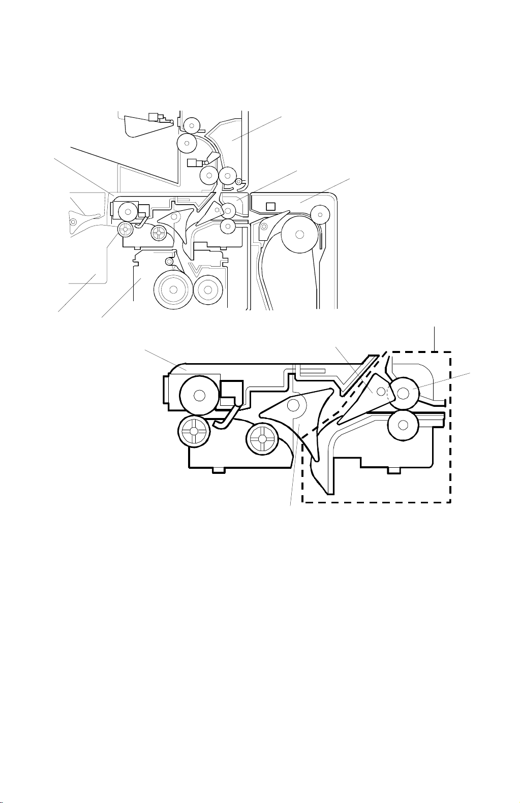
1.2 MECHANICAL COMPONENT LAYOUT
2
1
3
4
6
5
A690V500.WMF
1
1. Exit Unit (Inside the Copier)
2. 1-bin Tray (Option)
3. Interchange Unit
7
9
6. Bridge Unit (Option)
7. Duplex Junction Gate
8. Exit Roller
3
8
A690V501.WMF
4. Duplex Unit (Option)
5. Fusing Unit (Inside the Copier)
9. Exit Junction Gate (Inside the Copier)
A690-2
Page 4
26 March 1998 DRIVE LAYOUT
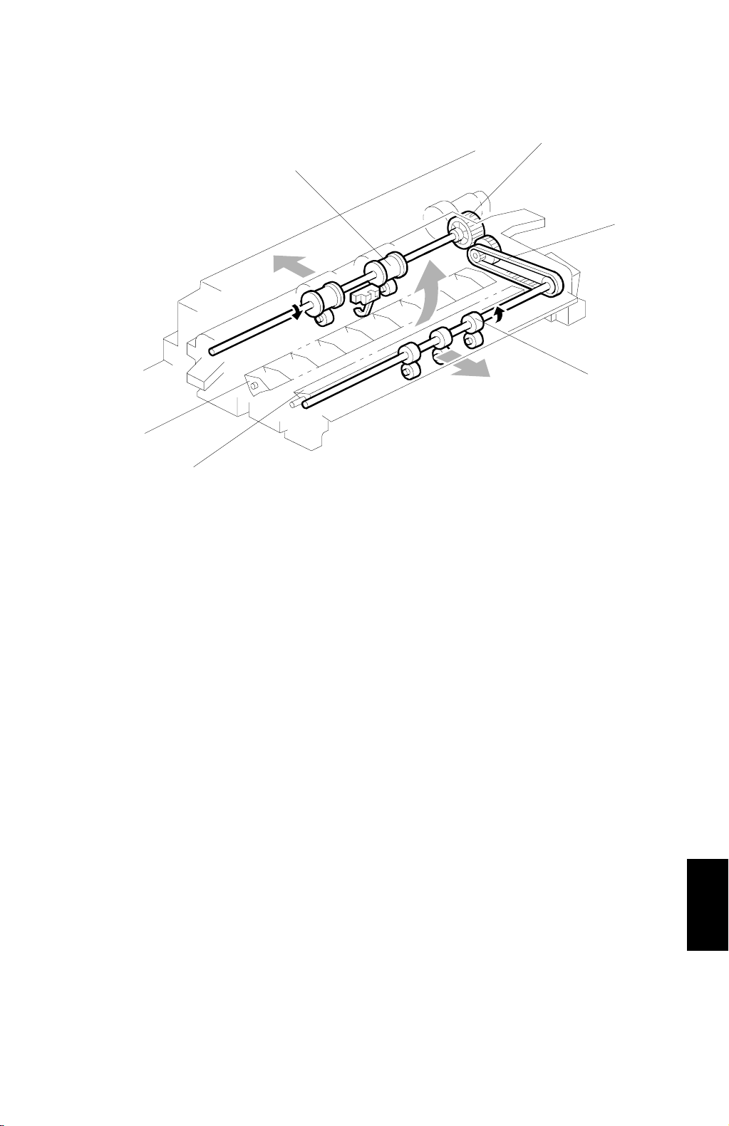
1.3 DRIVE LAYOUT
2
1
3
4
6
5
1. Exit Roller (Copier Exit Unit)
2. Exit Unit Drive Gear (Copier Exit Unit)
3. Exit Roller Drive Belt
A690V502.WMF
4. Exit Roller
5. Duplex Junction Gate
6. Exit Junction Gate (Copier Exit Unit)
A690-3
Options
Page 5
JUNCTION GATE MECHANISM 26 March 1998
2. DETAILED DESCRIPTION
2.1 JUNCTION GATE MECHANISM
- To the Exit Tray/Bridge Unit -
[E]
[C]
[A]
[D]
[A]
[B]
A690D500.WMF
- To the 1-bin Tra y -
[F]
[A]
[B]
[B]
A690D501.WMF
- To the Duplex Unit -
[A]
[B]
[G]
A690D502.WMF
A690D503.WMF
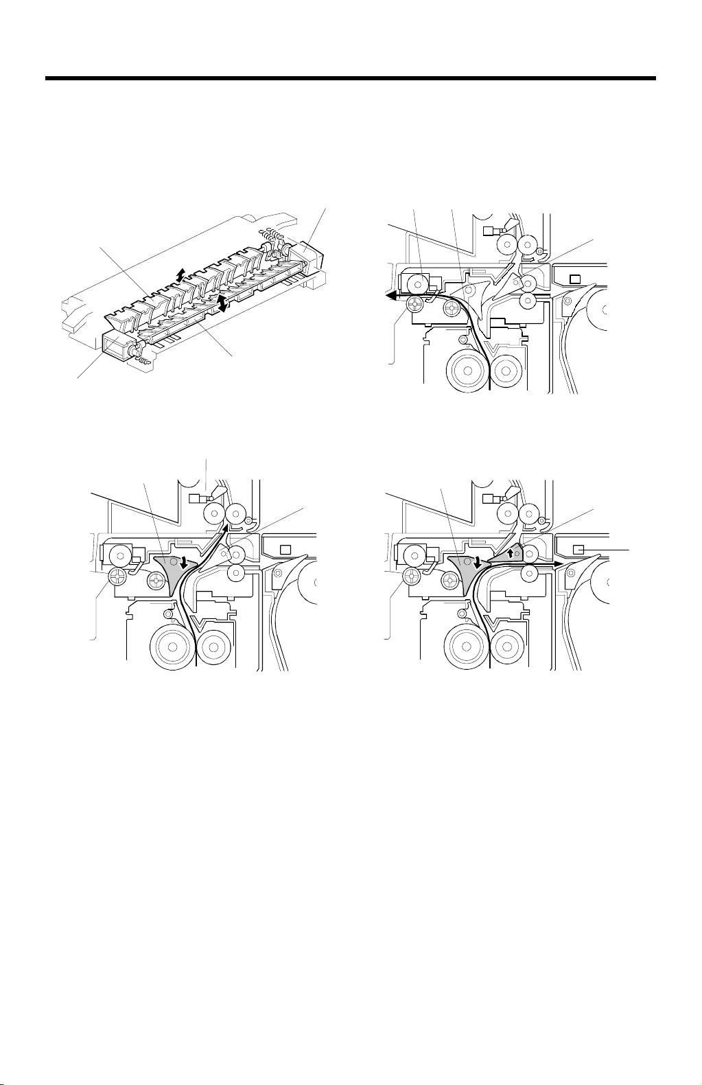
Depending on the selected mode, the copies are directed up, left , or ri ght by the
exit junction gate [A] in the copier and the duplex junction gate [B]. These are
controlled by the exit junction gate solenoid [C] and the duplex junction gate
solenoid [D].
To the Exit Tray or Bridge Unit (for the Upper Tray, Left Tray, or Finisher)
The exit junction gate solenoid stays off and the copy paper is directed to the
copier exit unit [E].
To the 1-bin Tray
The exit junction gate solenoid turns on and the duplex junction gate solenoid stays
off. The copy paper is directed to the 1-bin tray [F].
To the Duplex Unit
The exit junction gate solenoid and the duplex junction gate solenoid both turn on
and the copy paper is directed to the duplex unit [G].
A690-4
Page 6
26 March 1998 EXIT SENSOR (COPIER) REPLACEMENT
3. REPLACEMENT AND ADJUSTMENT
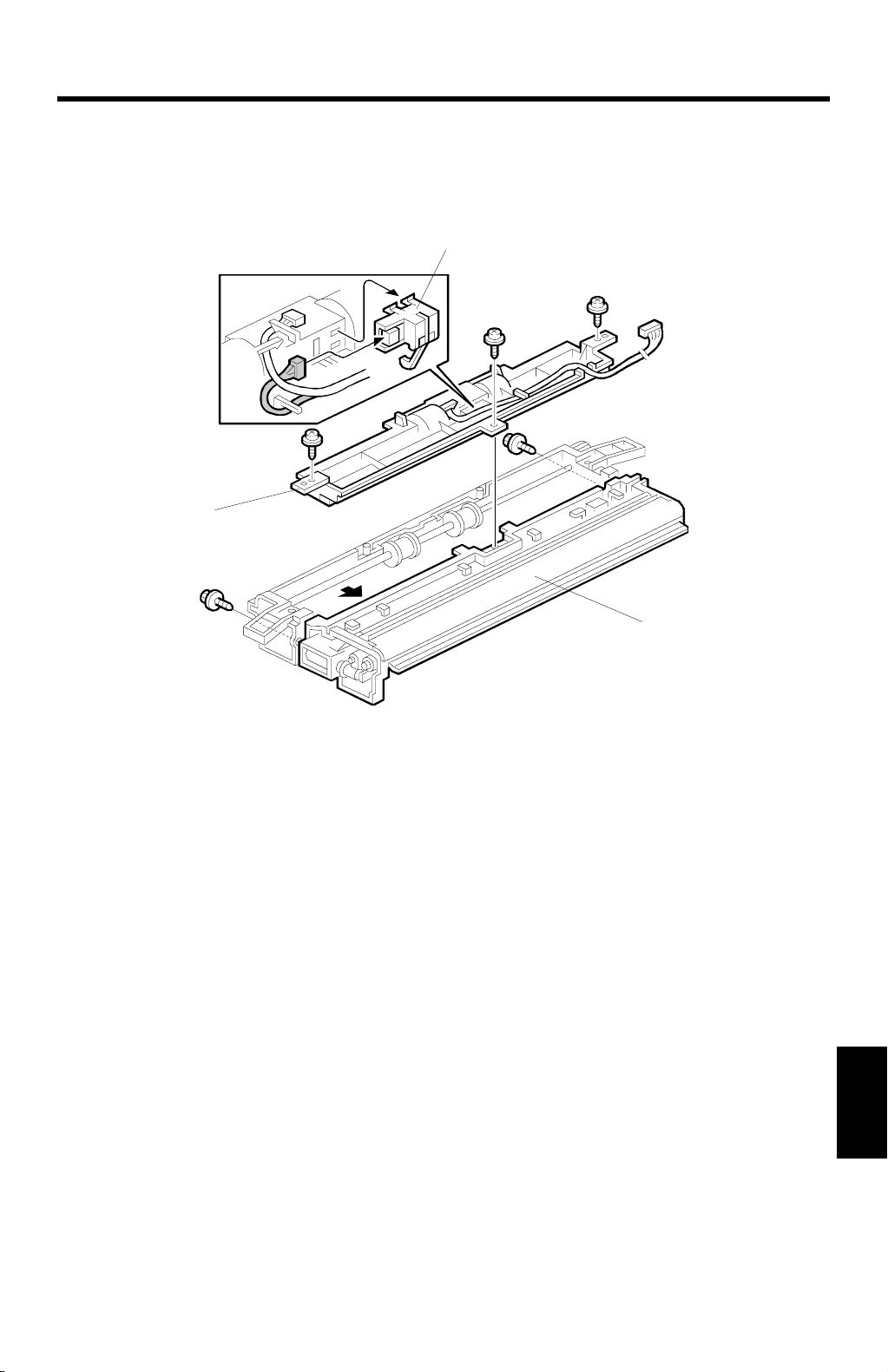
3.1 EXIT SENSOR (COPIER) REPLACEMENT
[C]
[B]
A690R500.WMF
1. Remove the scanner unit from the copier.
2. Remove the upper cover of the copier exit unit.
3. Remove the exit unit.
4. Remove the interchange unit [A] (2 screws).
5. Remove the interchange unit upper cover [B] (3 sc rews).
6. Replace the exit sensor [C] (1 connector).
[A]
A690-5
Options
 Loading...