

Page 1
MODIFICATION BULLETIN NO. 1 PAGE 1 OF 4
ISSUED ON: March 31, ’94
Model Priport Interface kit Code Model Name Serial Number
Modified Article C544 - 00
C544 - 01
Reason for
Spare Parts List for the Computer Interface Kit
Modification
Interface Unit
-10 Type 1
Interface Unit
-10 Type 2
Add the following parts list to the Prip ort part s cata logs. Note that there are two types for the kit: one is Interface Unit - 10
Type 2 (C544-01) for the N810 only, and the other is Type 1 (C544-00) for the other Priport mode ls.
Page 2
MODIFICATION BULLETIN NO. 1 PAGE 2 OF 4
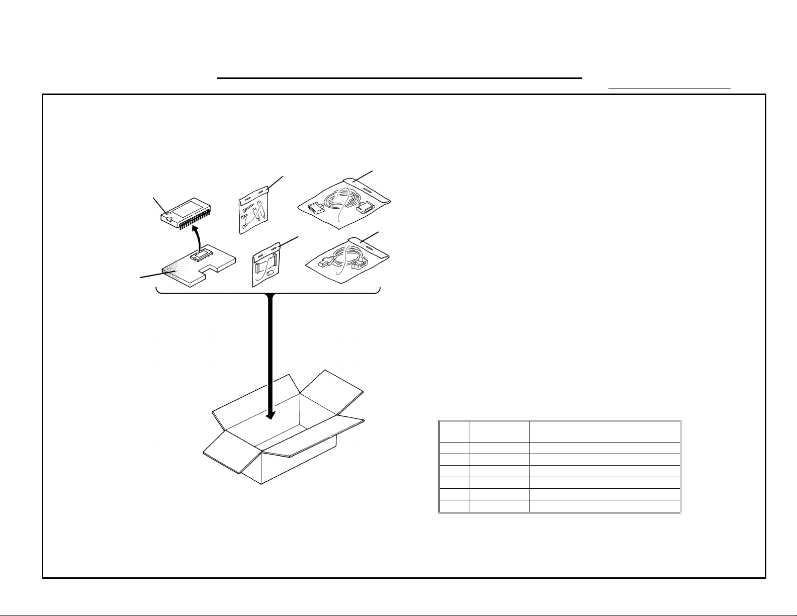
1. INTERFACE UNIT - 10 TYPE 1
ISSUED ON: March 31, ’94
3
4
1
2
5
6
INDEX PART NO DESCRIPTION
1 C544 1005 IC - Interface - AM27C512 - 150DC
2 -- Accessories for NA2
3 -- Accessories for N865
4 C544 1510 Controller Cable
5 C544 1500 Interfac e Cable - Type 1
6 C544 1100 Interface Board
Page 3
MODIFICATION BULLETIN NO. 1 PAGE 3 OF 4
14
ISSUED ON: March 31, ’94
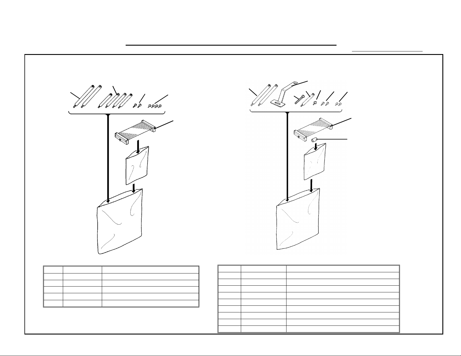
1. 1 Accessories for N865
7(4 pcs)
6(2 pcs)
8(2 pcs)
9(4 pcs)
10
1. 2 Accessories for NA2
13
15
16
17 18
19
11
12
Accessories for N865
INDEX PART NO DESCRIPTION
6 R326 5302 Interface Board Stud
7 C200 2596 Main Board Stud - Long
8 0314 0080Z Philips Screw - M4 x 8
9 0951 3006Z Philips Screw with Flat Washer - M3 x 6
10 C544 1601 Flat Cable - N865
Accessories for NA2
INDEX PART NO DESCRIPTION
11 C544 1602 Flat Cable - NA2
12 C203 2031 Main Board Spacer
13 C531 5300 Stud - Bracket - Interface
14 C531 5310 Interface Board Bracket
15 0951 3025Z Philips Screw with Flat Was her - M3 x 25
16 C209 8500 Stud - Main Board
17 0951 4006Z Philips Screw with Flat Was her - M4 x 6
18 0314 0080Z Philips Screw - M4 x 8
19 0951 3006Z Philips Screw With Flat Washer - M3 x 6
Page 4
MODIFICATION BULLETIN NO. 1 PAGE 4 OF 4
13
7
ISSUED ON: March 31, ’94
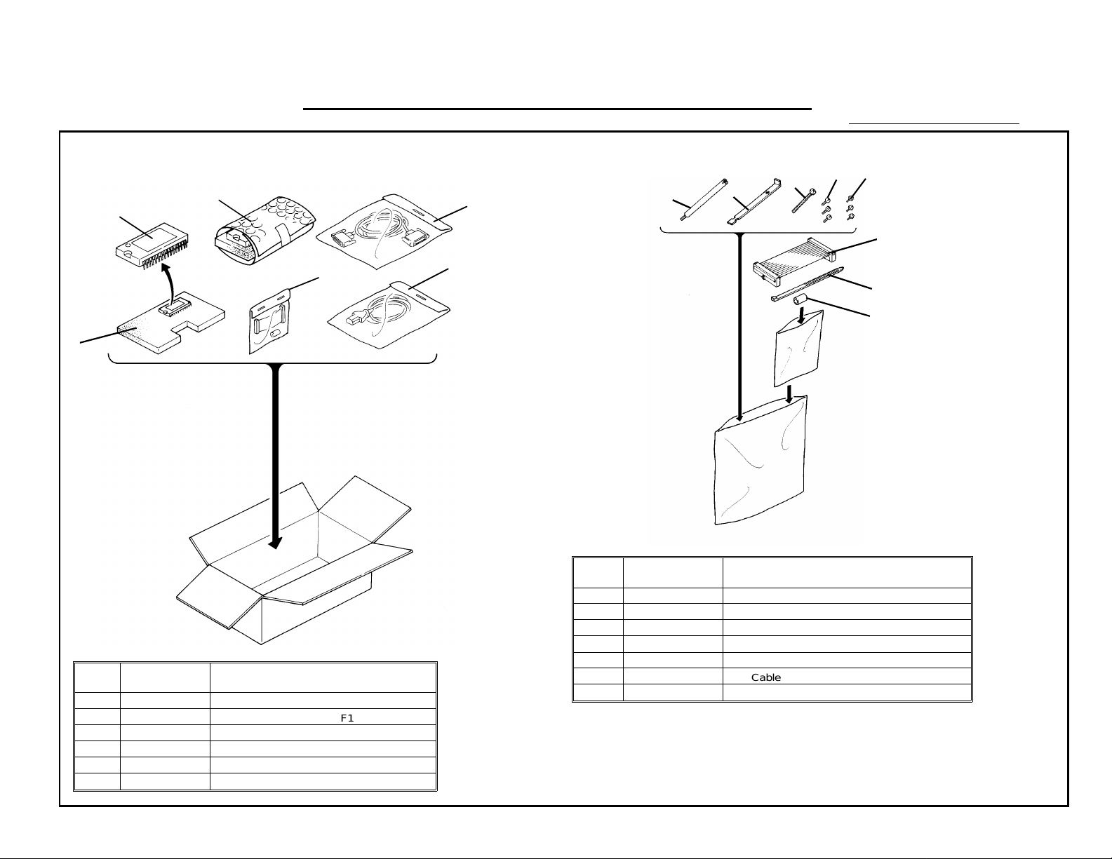
2. INTERFACE UNIT - 10 TYPE 2
1
6
PART
NO
1 C544 1005 IC - Interface - AM27C512 - 150DC
2 C544 1301 IC - Main - M27C 512-12F1
3 C544 1510 Controller Cable
4 -- Accessories for N810
5 C544 1501 Interface Cable - Type 2
6 C544 1100 Interface Board
INDEX DESCRIPTION
2
4
2. 1 Accessories for N810
8
3
6
109
11
5
12
Accessories for N810
PART
NO
6 C544 2110 PCB Stud
7 C544 2112 Harness Support Bracket
8 0313 0350B Philips Pan Head Screw - M3 x 35
9 0960 3008W Philips Flange Screw - M3 x 8
10 0960 4008W Philips Flange Screw - M4 x 8
11 C544 1600 Flat Cable - N810
12 1105 0042 Wi re Band
INDEX DESCRIPTION
S. Hamano, Assistant General Man ag er
Technical Support Departme nt
Page 5
MODIFICATION BULLETIN NO. 2 PAGE 1 OF 1
ISSUED ON: February 15, ’95
Model Priport Interface Kit Code Model Name Serial Number
Modified Article Sleeve Core and Insulating Sheet C544-00
C544-01
Reason for
Due to missing infomation from the parts list on MB No.1
Modification
Interface Unit
- 10 Type 1
Interface Unit
- 10 Type 2
The following two parts were missing from the parts list in MB No. 1:
P/N Description Q’ty Used Index Location in MB No. 1
C5442105 Insulating Sheet - 145 x 200 (Plastic Sheet) 1 * 11 Page 3 of 4, Accessories for N865
16070576 Sleeve Core - SFC-8 (Ferrite Core)
1 * 7 Page 2 of 4, INTERFACE UNIT - 10 TYPE 1
1 * 7 Page 4 of 4, INTERFACE UNIT - 10 TYPE 2
* New Index
Note:
1. The plastic sheet is used only for the N865/ 86 0 (Ricoh VT21 05 /V T20 05 , Ge ste tn er 5325 /5 32 3, Re xRot ary
1250/1245, Nashuatec CP 325/CP323, A.B. Dick 6520) and the other old er models. It is to be installed under the
interface board accord ing to th e inst allation procedure (booklet ) packed with the kit. This is an EMI
(ElectroMagnetic field Interference) standard requirement.
2. The ferrite core is to be fitted on the cable between the Priport and controller (C5441 510). Fit the ferrite core on
the Priport end of the cable (approximately less than 20 mm from t he end).
S. Hamano, Assistant General Manager
Technical Support Department
Page 6

MODIFICATION BULLETIN NO. 3 PAGE 1 OF 2
ISSUED ON: February 15, ’95
Model Priport Interface Kit Code Model Name Serial Number
Modified Article Flat Cable for NA3 / NB2 C544-00
C544-01
Reason for
To enable installation of the kit in the NA3 / NB2 models (For Type 1 only)
Modification
Interface Unit -
10 Type 1
Interface Unit -
10 Type 2
To enable installation of the kit in the NA3 / NB2 mode ls (Ricoh VT3 600 / VT2 60 0 / VT 2630 , Ge ste tn er 5380 / 5360,
RexRotary 1285 / 1270, Nash ua te c CP38 0 / CP360, A. B. Dick 6770), the follo wing part has been added to the In te rface
Unit 10 Type 1 (C544-00):
Part Number Description Q’ty Index No. Location in MB No. 1
C5441600 Flat Cable - N810 1 * 20
Page 3 of 4,
Accessories for NA2
NOTE:
1. This flat cable is commonly used for th e N81 0 (Ricoh VT17 30, Ge stetner 5303, RexRotary 1220, Nashu atec
CP303, A. B. Dick 6120), and is also packed in the Interface Unit 10 Type 2 (C544-01).
4060001
2. For installation in the NA3 / NB2 models, use the accessorie s f or th e NA2 (Ricoh VT3500, Gestet ne r 537 5,
RexRotary 1280, Nashuate c CP37 5, A. B. Dick 6720) except for the flat cable.
Page 7

MODIFICATION BULLETIN NO. 3 PAGE 2 OF 2
ISSUED ON: February 15, ’95
DETAILS OF MODIFICATION
3. Note that the dip switch settin g of the in terface board (DPS101) is different between the NA3 and NB2. (The NA3’s
setting is the same as that of the NA2.)
DPS101 - 1 -2 -3 -4
NA3
(Ricoh VT3600, Gestetner 5380, RexRotary 1285, nashuatec CP380,
A. B. Dick 6770)
NB2
(Ricoh VT2600 / VT2630, Gestetener 5360, RexRotary 1270,
nashuatec CP360)
ON ON ON OFF
OFF ON ON OFF
The installation procedu re (bo oklet) packed in the kit has been updated at the same time, and this inf orma tion (also how to
install the kit in the NA3 / NB2 models) has been added.
S. Hamano, Assistant General Manager
Technical Support Department
Page 8

MODIFICATION BULLETIN NO. 4 PAGE 1 OF 1
ISSUED ON: February 15, ’95
Model Priport Interface Kit Code Model Name Serial Number
Modified Article ROM for N810 Main Board C544-00
Reason for
Modification
To make the installation of the Interface Unit 10 Type 2 easier (For Type 2
only)
C544-01
Interface Unit -
10 Type 1
Interface Unit -
10 Type 2
4080001
To enable the installation of the Int erf ace Unit 10 Type 2 (C544-01) in the N810 (Ricoh VT1730 , Geste tn er 53 03 ,
RexRotary 1220, Nashuatec CP3 03 , and A. B. Dick 612 0) with ou t rep lacin g th e ROM on the N8 10’s ma in board, the ROM
has been changed from C2178 00 5 to C217 80 15 . When you install the Interface Unit 10 Type 2 in the N810 which ha s the
new ROM, you do not have to replace th e ROM on the N810’s ma in board with the ROM packed in the Interface Unit 10
Type 2. (For the cut-in serial number, refer to N810 MB-022.)
Also for the Interfa ce Unit Type 2, the ROM has been change d du e to part st anda rdization as follows:
Old P/N New P/N Description Index No. Location in MB No. 1
Page 4 of 4,
C5441301 C2178015 IC - Main - M27C512-12F1 2
INTERFACE UNIT - 10
TYPE 2
This ROM is used only when the kit is installed in an N810 which has the old type ROM.
S. Hamano, Assistant General Manager
Technical Support Department
Page 9

MODIFICATION BULLETIN NO. 5 PAGE 1 OF 9
ISSUED ON: November 30, 95
Model Priport Interface Kit Code Model Name Serial Number
Modified Article C544 - 00
Reason for
Modification
Spare Parts List for the New Computer Interface Kit
(To unify Type 1 and Type 2)
Interface Unit
- 10 Type 1
5070001
To allow the Interfa ce Unit - 10 Type 1 (C544-00) to cover all the Priport mo de ls, some parts have been changed as
described on page 7 and therea ft er. As a result, Type 2 (C544-01) has been disco ntinued and the new Type 1 will be used
also for the N810.
The new Type 1 kit includes 4 sets of the accesso ries (ea ch of the m is packed in a small plastic bag) and the sets are
named "for PART 1A", "f or PA RT 1 B", "f or PART 1C", or "for PART 1D". Each se t corre sponds to the appropriate Pripo rt
models as follows:
Name of the set Applicable Priport Models (Code Name) Note
This set was in the Type 2 kit. The ROM for the main
for PART 1A N810, N810-II
body’s main board has been removed and some parts
have been newly added. See page 5 for details.
for PART 1B NA33, NA3, NA2, NB2
for PART 1C N850, N865, and the other older Priport models
for PART 1D RN925 This set has been newly added. See page 6.
Page 10

MODIFICATION BULLETIN NO. 5 PAGE 2 OF 9
ISSUED ON: November 30, 95
NOTE: - A decal that indicates th e name of the set is attached on each plastic bag fo r iden tif icat ion .
- For the model names for each code name, refer to the followin g " Model Name and Code Name Cross
Reference Table" (see page 3).
- The installation proced ure (booklet) packed in the kit ha s bee n upda te d at the same time.
- The sets for PART 1A, for PART 1 B, and for PA RT 1 C include a flat cable, which conne cts th e interface
board to the main body’s main boa rd. Note that those flat cables are used for dif ferent Priport models
in some cases. Each flat cable corresp onds as follows:
Part Number Location Applicable Priport Models (Code Name)
C5441600 PART 1A N810, N810-II, N850, RN925, NB2, NA3, NA33
C5441602 PART 1B NA2
C5441601 PART 1C N865 and the other older Priport models
Page 11

MODIFICATION BULLETIN NO. 5 PAGE 3 OF 9
Model Name and Code Name Cross Ref er ence Table
Code Name Code # Model Name
N810 C217 Ricoh VT1730, NRG 5303 / 1220 / CP303, AB DICK 6120
N810 - II C225 Ricoh VT1800, NRG 5304 / 1222 / CP304, AB DICK 6130
N865 C216 Ricoh VT2105, NRG 5325 / 1250 / CP325, AB DICK 6520
N850 C224 Ricoh VT2200, NRG 5327 / 1252 / CP327, AB DICK 6530
RN925 C222 Ricoh VT2400, NRG 5340 / 1255 / CP340, AB DICK 6550
NB2 C219 Ricoh VT2600 / VT2630, NRG 5360 / 1270 / CP360
NA2 C210 Ricoh VT3500, NRG 5375 / 1280 / CP375, AB DICK 6720
NA3 C218 Ricoh VT3600, NRG 5380 / 1285 / CP380, AB DICK 6770
ISSUED ON: November 30, 95
NA33 C223 Ricoh VT3800, NRG 5385 / 1290 / CP385, AB DICK 6790
Page 12

MODIFICATION BULLETIN NO. 5 PAGE 4 OF 9
9
PART LIST for NEW INTERFACE UNIT - 10 TYPE 1
3
1
5
7
ISSUED ON: November 30, 95
2
4
6
8
INDEX PART NO DESCRIPTION
10 -- Accessories for PART 1B
10
1 C544 1015 IC - Interface - AM27C512 - 150DC
2 C544 1010 Interface Board
3 C544 1510 Controller Cable
4 C544 1520 Interface Cable - Interface Board
5 1607 0576 Sleev e Core - SFC-8
6 C544 2105 Insulating Sheet - 145 x 200
7 -- Accessories for PART 1A
8 -- Accessories for PART 1D
9 -- Accessories for PART 1C
Page 13

MODIFICATION BULLETIN NO. 5 PAGE 5 OF 9
ISSUED ON: November 30, 95
1. Accessories for PART 1A
11
12
13
14
15
16
19
20
18
17
2. Accessories for PART 1B
23
26
25
24
27
28 29
21
22
Accessories for PART 1A
PART
NO
11 C544 2116 Stud - 50 mm
12 0807 3083 Spacer - 10 mm
13 C544 2110 PCB Stud - 64 mm
14 C544 2112 Harness Support Bracket
15 0313 0350B Philips Pan Head Screw - M3 x 35
16 0960 3008W Phil ips Flange S crew - M3 x 8
17 0960 4008W Phil ips Flange S crew - M4 x 8
18 C544 1600 Flat Cable - N810 / NA33 / NA3 / NB2 / RN925 / N850
19 1105 0042 Wire Band
20 C544 2111 PCB Collar
INDEX DESCRIPTION
Accessories for PART 1B
INDEX PART NO DESCRIPTION
21 C544 1602 Flat Cable - NA2
22 C203 2031 Main Board Spacer
23 C531 5300 Stud - Bracket - Interface
24 C531 5310 Interface Board Bracket
25 0951 3025Z Philips Screw with Flat Washer - M3 x 25
26 C209 8500 Stud - Main Board
27 0951 4006Z Philips Screw with Flat Washer - M4 x 6
28 0314 0080Z Philips Screw - M4 x 8
29 0951 3006Z Philips Screw With Flat Was her - M3 x 6
Page 14

MODIFICATION BULLETIN NO. 5 PAGE 6 OF 9
ISSUED ON: November 30, 95
3. Accessories for PART 1C
31
30
32
33
34
4. Accessories for PART 1D
35
36
37
Accessories for PART 1C
INDEX PART NO DESCRIP T IO N
30 R326 5302 Interface Board Stud
31 C200 2596 Main Board Stud - Long
32 0314 0080Z Philips Screw - M4 x 8
33 0951 3006Z Philips Screw with Flat Washer - M3 x 6
34 C544 1601 Flat Cable - N865
Accessories for PART 1D
INDEX PART NO DESCRIPTION
35 C544 2120 Stud - 35 mm
36 0951 3006Z Philips Screw With Flat Washer - M3 x 6
37 0314 0080Z Philips Screw - M4 x 8
– C544 2330 Set For PART 1D (See page 8)
Page 15

MODIFICATION BULLETIN NO. 5 PAGE 7 OF 9
OLD
ISSUED ON: November 30, 95
The following shows details of the modificat ion s applied for the new kit:
1. A new decal that indicates the names of the sets for PA RT 1A, for PART 1B, for PART 1C, and PA RT 1D is at ta ched on
each plastic bag for identification.
2. To enable the installation of the kit for the N810 and N810 -II , some parts have been added as "for PA RT 1 A" (se e pa ge
5), which were used in the "Typ e 2" kit. Also, to use the same cable (going to the rear of th e machine from the interface
board) as that used for th e other models, some new parts have been added as shown below. The old cable (P/N C5441501) is no longer needed. (The old cable can still be used for the N810 and N810-II without these new parts.
However, the cable, P/N - C544 15 00 , which is the old type for the othe r mode ls, cannot be used for the N810 and
N810-II even with these new parts. This is because the bracket of the new cable (P/N - C54 4152 0) ha s a new
configuration .)
C5441501
NEW
08073083
C5442116
09604008W
C5441520
Page 16

MODIFICATION BULLETIN NO. 5 PAGE 8 OF 9
ISSUED ON: November 30, 95
3. To enable the installa tio n of the kit for the RN925, some ne w part s have been added as "for PART 1D" (see page 6).
Also, the cable going to the rear of the machine from th e interface board has been lengthened by 100 mm (P/N C5441500 has been chang ed to P/ N - C5441 52 0) since the old cable was too short for the RN925 .
(See page 4. The new cable is used for all mode ls.) The new ROM is also req uired (see the next page).
NOTE:1. If you use the old interf ace unit - 10 Type 1 for the RN925 , you need th e following parts:
1) All parts for PART 1D (see pa ge 6). You ca n ord er these parts as a set with
P/N - C5442330 (Set For PART 1D).
2) The new cable (P/N - C5441520).
3) The new ROM on the interface board (P/N - C5441015).
2. If you use the old interf ace unit - 10 Type 1 for the N850, you nee d th e ne w ROM
(P/N - C5441015) only.
3. If you use the old interf ace unit - 10 Type 2 for the N810-II, you need the new ROM
(P/N - C5441015) only.
4. For the other older mo dels, the old Type 1 can be used (the Type 2 for th e N81 0).
Page 17

M. Iwasa, Manager
Technical Support Department
MODIFICATION BULLETIN NO. 5 PAGE 9 OF 9
ISSUED ON: November 30, 95
4. Due to the following reasons, the ROM on the inte rfa ce bo ard has be en chan ged fro m P /N - C544 1005 to P/ N - C5441 01 5.
At the same time, the part number of th e interface board has also been changed from C54411 00 to C5441 01 0 for
identification purposes.
(1) The new ROM enables operating th e lat est Pripo rt mod els (NA33, RN925, N850, and N810-II) with th e con tro ller.
The following are the features unique to these Priport mode ls:
- Auto On-line -
When data is sent from the controller, the Priport enters the On-lin e mode auto mat ically.
- Auto Off-line -
When the Priport stops while operating in the On-lin e mod e due to the end of a job, running out of paper,
or a paper or master jam, etc., the On-line mode is auto mat ically can celed.
(2) The number of prints can be set from the computer. (This is possible only with the Prip ort N810, N810-II, N850, NB2,
RN925, NA3, NA33, and other fu ture models.) Also, if the Priport has a paper size detection system, the size of th e
paper set in the Priport is compared wit h th e pa pe r size se lect ed on th e comp uter when the data is sent fro m t he
computer. If they are different, the controller resets the print number to 2 (as a print number of 1 cannot be used in
this case) in order to minimize unusable printo uts. (This is possible only with the Priport NB2, RN925, NA 3, NA33 ,
and other future models that can detect the paper size.)
NOTE: 1. These functions can be used since version 2.02 of the old interface bo ard ROM (P/N - C5441005).
However, only the new ROM (P/N - C5441015) can be used for th e Priport NA33, RN925, N850,
and N810-II.
2. The controller that supports th ese functions must be used.
(The cut-in serial numbers are : 51504090001 for the NRG version and C3239409 0001 for Ricoh ’s.)
3. For the N810, the ROM on the main board (P/N - C2178015) must be cha ng ed to th e ne w version
(P/N - C2178016).
4. To enable these functions, all dip switch es on the inte rface board (DPS101 - 1, -2, -3, and -4) must be
set to OFF.
 Loading...