

Ricoh HS2P PLUS Service Manual
RICOH Technical
Reissued: 23-Mar-00
Bulletin
PAGE: 1/2
Model:
IS450 / IS450DE/V
Date:
17-Feb-00
No.:
RG407001a
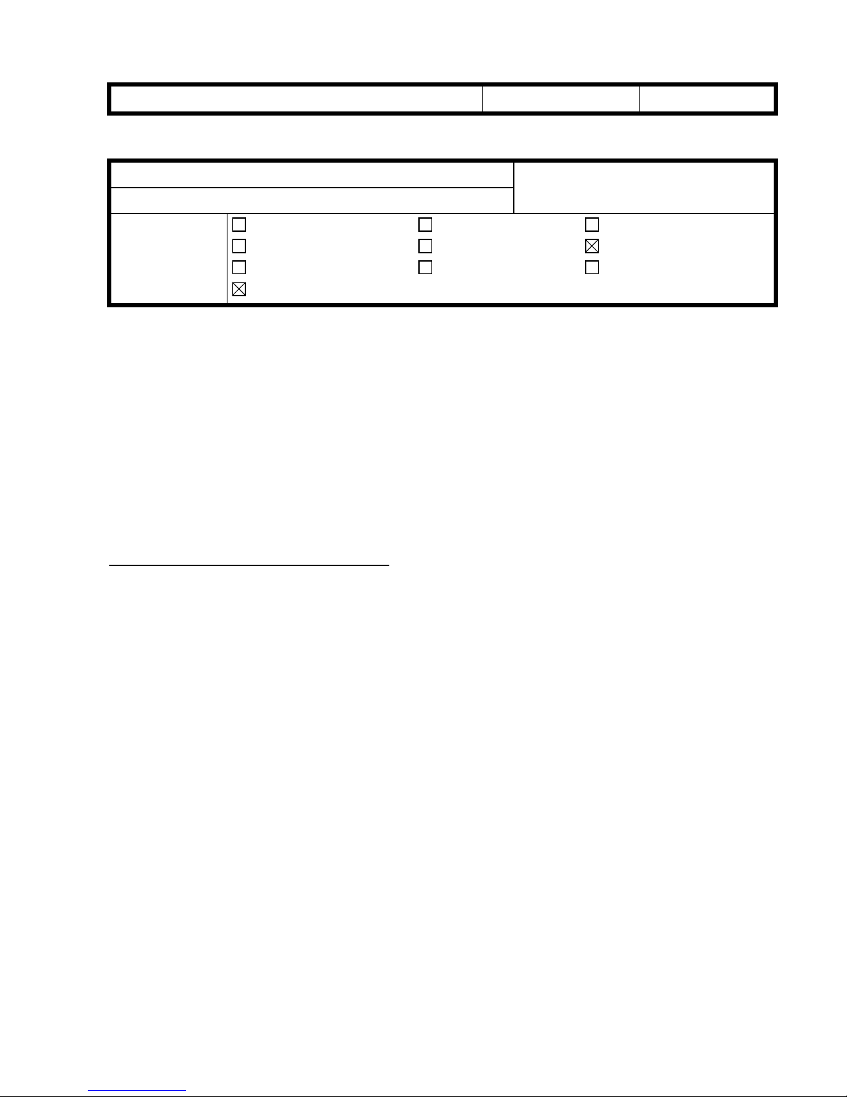
RTB Correction
The items in bold italics have been corrected or added.
Subject:
From:
Classification:
In preparation for HS2P+ mass production set to begin later this month, this RTB will
explain the differences between the HS2P and HS2P+. T heref ore, there will be no Service
Manual released for the HS2P+.
The HS2P+ was developed for use with the KOFAX VRS system only, and many of its
components have been modified from the HS2P. A fter bei ng connec ted to the R SC U
board, the KOFAX VRS board acts as an interface to forward the image data to the PC.
The following is a description of the differences between the HS2P and HS2P+, along with
a list of the sections of the Service Manual that require revision.
Diffarence between HS2P and HS2P+
Technical Services Dept., GTS Division
Troubleshooting
Mechanical
Paper path
Other ( )
Part information
Electrical
Transmit/receive
Prepared by:
Action required
Service manual revision
Retrofit information
E. Fukuyama
The following are the revisions made to the HS2P+ from the HS2P.
General differences from the HS2P:
1. In order to enable Auto Original Detection as well as Auto Skew Detection, the color of
the Platen Cover Sheet has been changed from white to black.
Modifications made to: Platen Cover Sheet, ADF Guide Plate, and Rear Roller.
2. In order to enable Grayscale Image Processing for the rear side of the scanned original,
a 32MB SIMM has been added.
Modifications made to: RCU Board.
3. A KOFAX VRS board is used as the interface between the scanner and PC.
Since this video interface is now used for scanner/PC communication, the SCSI I/F will
only be used by the service technician to diagnose problems with the scanner.
Therefore, a cover has been placed over the two SCSI interfaces.
Note: Ricoh’s product liability is limited to the scanner mainframe, the harness that
connects to the VRS interface board, and the connector on the VRS board for this
harness.
4. A Shading Calibration Sheet has been registered as a Service Part.
Since the rear roller in the HS2P+ is black, it is not possible to use the roller for rear side
shading. This is why a Shading Calibration Sheet was added. The shading data is
controlled by the KOFAX driver.
The RSCU board sends the data to the VRS board, and the data is not saved inside the
HS2P+ itself.
RICOH Technical
Reissued: 23-Mar-00
Bulletin
PAGE: 2/2
Model:
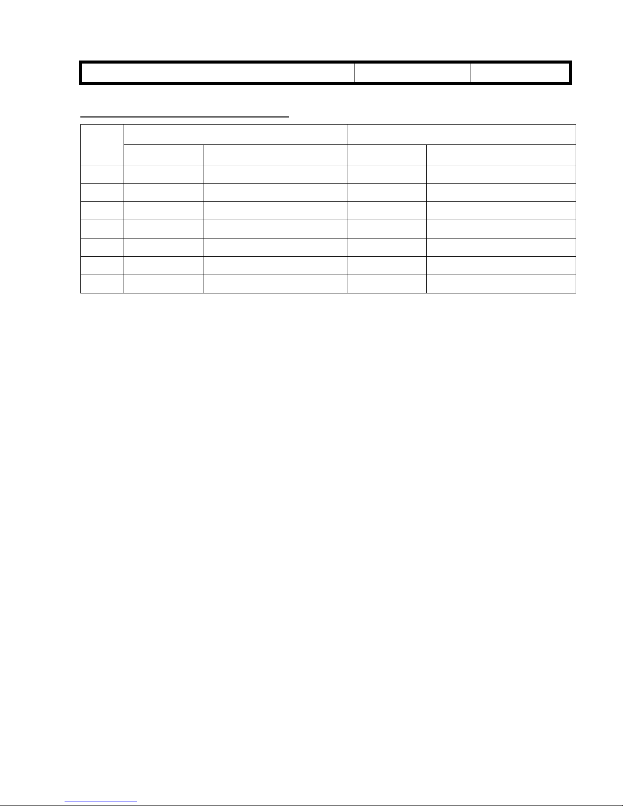
Differences in internal components:
Index
17-14 G4074039 Platen Cover Sheet G4134039 Platen Cover Sheet Black
11-17 G4083501 Rear Roller G4133501 Rear Roller Black
23-6 G4085100 RCU Board G4135101 ERCU Board
---- ----- ----- G4135150 SIMM 8M X 32 BIT 60ns
---- ----- ----- G4133590 Shading Calibration Sheet
---- ----- ----- G4131056 SCSI I/F Cover
IS450 / IS450DE/V
HS2P HS2P+Page-
Part number Description Part number Description
9-4 G4073345 ADF Guide Plate G4133347 ADF Guide Plate Blac k
Date:
17-Feb-00
No.:
RG407001a

HS2P PLUS
(Machine Code: G413)
Service Manual
Issued on February 16, 2000
Ricoh Co., LTD

16 February 2000 SPECIFICATIONS
1-1
Overall
Information
1. OVERALL MACHINE INFORMATION
1.1 SPECIFICATIONS
1.1.1 MAIN BODY
Scanning method: Flat-bed with ADF
Book scan: Horizontal: Max. 298 mm [11.7"]
Vertical: Max. 432 mm [17.0"]
ADF: Document size:
Width: 69 ~ 298 mm [2.7" ~ 11.7"]
Length: 120 ~ 2,000 mm [4.7" ~ 78.5"]
All pages in a document must be the
same width
Document weight: 41 ~ 128 g/m2 [11 ~ 34 lb.]
ADF capacity:
150 sheets (64 g/m2 [20 lb.])
110 sheets (105 g/m2 [24 lb.]/A4, A5, LT, HLT)
80 sheets (105 g/m2 [24 lb.]/A3, DLT)
Stack height must be less than 15 mm [0.6"]
Scanning resolution: Simplex mode:
Main scan: 100 ~ 800 dpi (in 1 dpi steps)
Sub scan: 100 ~ 800 dpi (in 1 dpi steps)
Duplex mode:
Main scan: 100 ~ 600 dpi (in 100 dpi steps)
Sub scan: 100 ~ 600 dpi (in 100 dpi steps)
Grayscales: 8 bits/pixel
Initialization time: About 15 seconds
Scanning speed: 0.65 s/200 dpi (A4, binary picture mode)
Scanning throughput: Simplex mode: 55 ppm/200 dpi
(A4, binary picture mode)
Duplex mode: 86 ipm/200 dpi
(A4, binary picture mode)
(Counted from the second page)
Interface: Expansion Interface: 60 pin
SCSI: The specification of SCSI I/F are only for
field service purpose.
Power: 1) 102 to 138 V ac (45 to 65 Hz)
2) 187 to 276 V ac (45 to 65 Hz)
Power consumption
(without all possible options):
Standby: 90 W Max.
Scanning: 120 W Max.
SPECIFICATIONS 16 February 2000
1-2
Operating environment:
Temperature: 10 to 32°C [50 to 90°F]
Humidity: 20 to 80% RH
Weight: Less than 27 kg [59.5 lb.]
Dimensions (W x D x H): 470 x 677 x 278 mm [18.5" x 26.7" x 10.9"]
1.1.2 ENDORSER
Number of printable characters: 19 characters (max)
Character set: 43 characters
0123456789#./-:,’AB ····Z
Character size: 1.6 (W) x 2.8 (H) mm
Character pitch:
2.4 mm ± 20%
Printable lines: 1 line (main scan direction)
Inking: Ink roll type
Ink refill: Ink roll exchange
Ink color: Purple
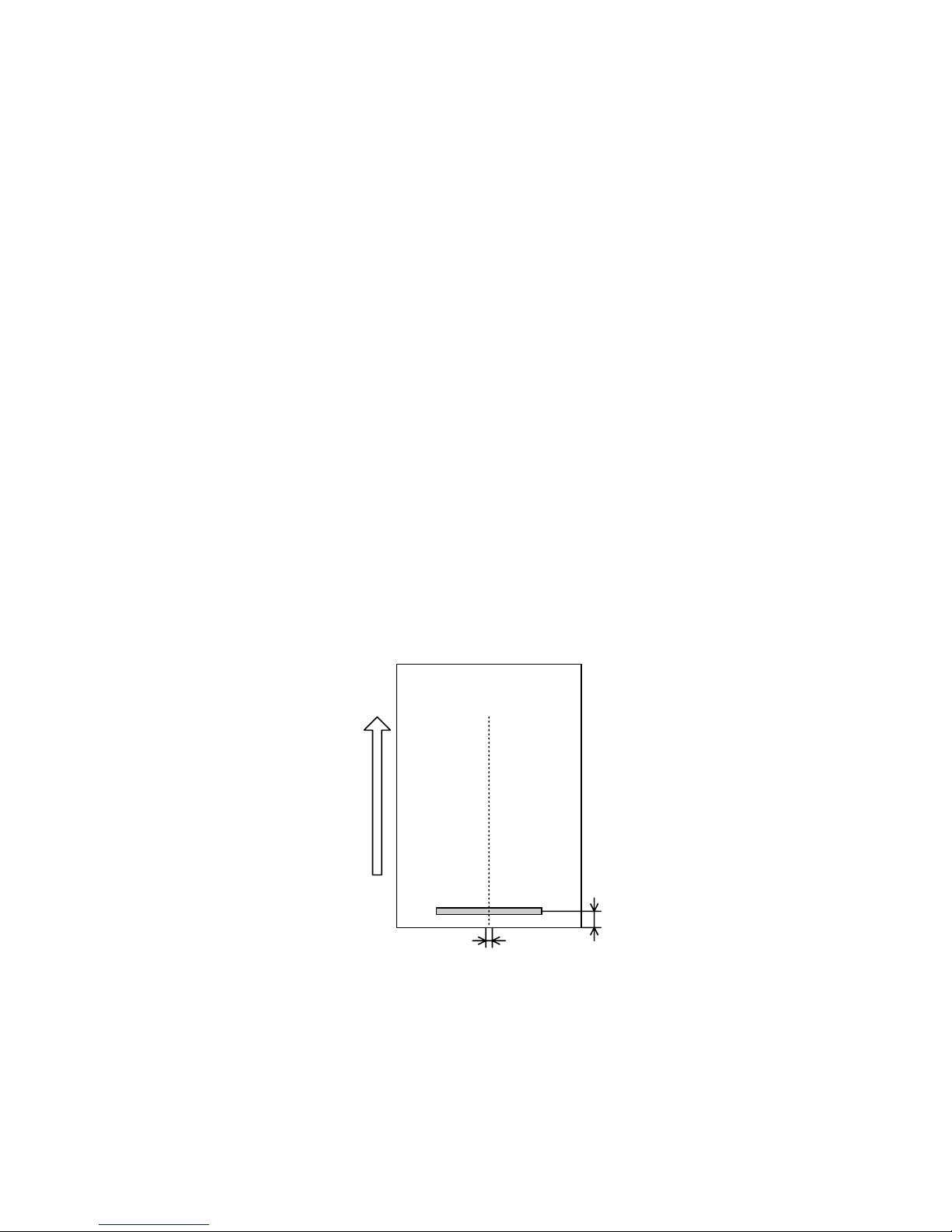
Print position:
a: 7 ± 4 mm
b: 0 ± 5 mm
Document
front side
Document Feed Direction
a
b
G413V506.WMF
COMPONENT LAYOUT 16 February 2000
1-4
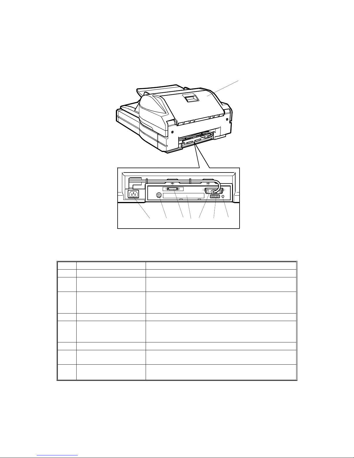
1.2.2 REAR VIEW
No. Name Function
7 Reset switch If this is pressed, the machine is reset.
8
DIP switches
Used to select various scanning modes and test
modes.
9
Interface for reverse side
scanning
(Duplex model only)
Interface for the video signal during reverse side
scanning.
10 Video connector For connecting the video cable
11
SCSI ID rotary switch
Used to select the SCSI ID and to select diagnostic
tests. Note that positions 8 and 9 are interpreted as
SCSI ID 7.
12 Power plug inlet For connecting the power cord.
13
ADF cover Open this cover to clear paper jammed at the input
side.
14
SCSI connectors cover
and SCSI connectors
(For connecting the SCSI cables.)
G413V501.WMF
13
101112 789
14
 Loading...