

Page 1

Model HL-F1
Machine Code: H558
Field Service Manual
14 May, 2010
Page 2

Page 3
Safety Precautions
To use the machine safely
Please keep these instructions for later reference and read them before attempting any maintenance.
• If there are faxes in the machine's memory, you need to print them or save them before you turn off
the power and unplug the machine.
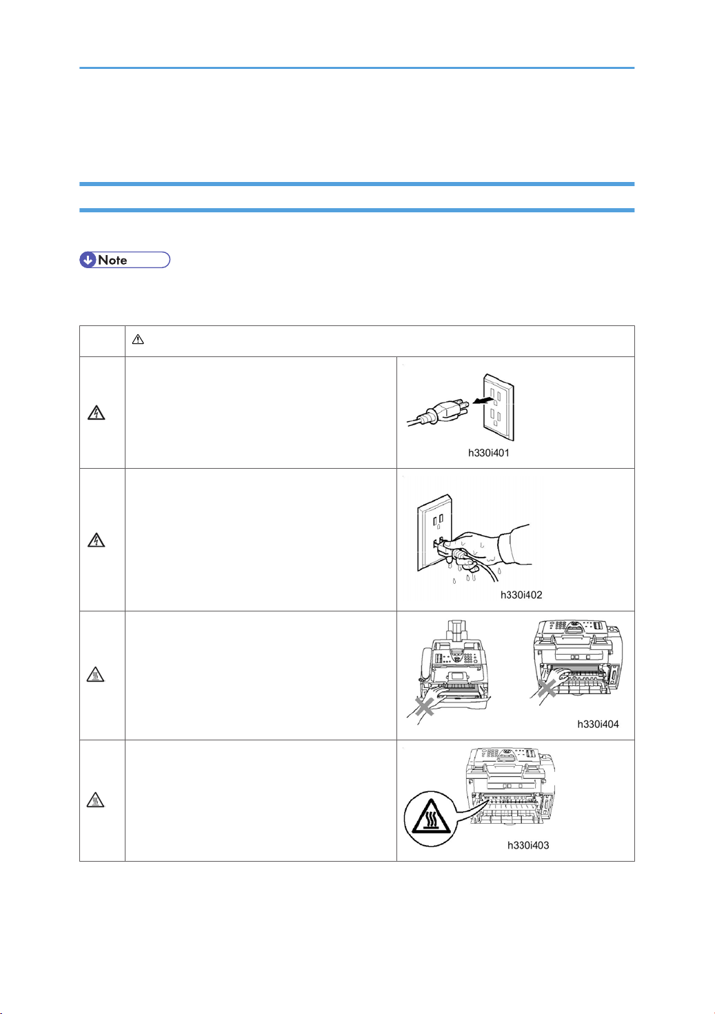
WARNING
There are high voltage electrodes inside the
machine. Before you clean the inside of the
machine, make sure you have unplugged the
telephone line cord first and then the power cord
from the AC power outlet.
Do not handle the plug with wet hands. Doing this
might cause an electrical shock.
After you use the machine, some internal parts are
extremely
to put your fingers in the area shown in the
illustration.
The fixing unit is marked with a caution label.
Please do not remove or damage the label.
• Use caution when installing or modifying telephone lines. Never touch telephone wires or terminals
that are not insulated unless the telephone line has been disconnected at the walljack.
HOT! To prevent injures, be careful not
1
Page 4
Never install telephone wiring during a lightning storm. Never install a telephone wall jack in a wet location.
• This product must be installed near an AC power outlet that is easily accessible. In case of an
emergency, you must disconnect the power cord from the AC power outlet to shut off the power
completely.
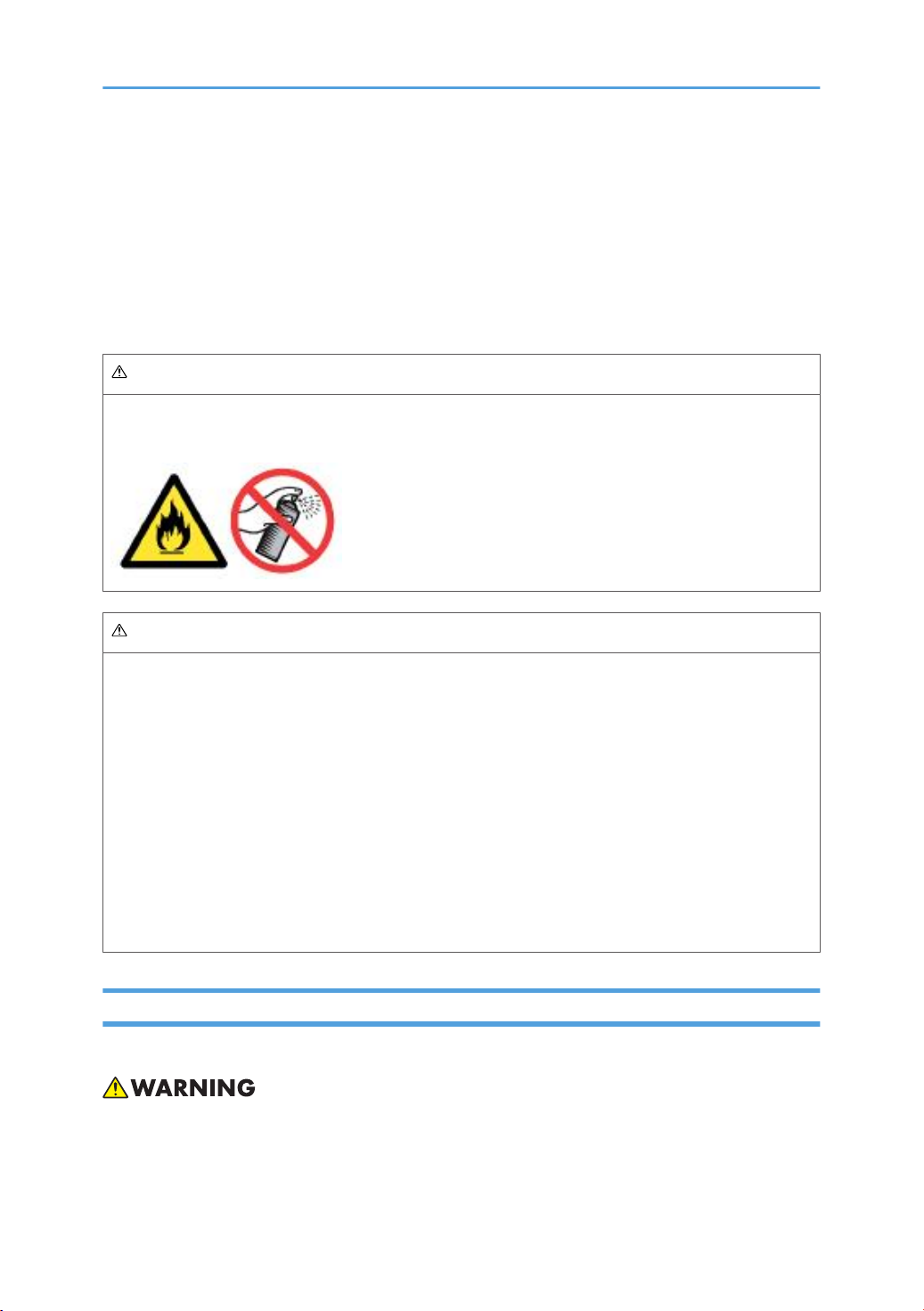
Do not use a vacuum cleaner to clean up scattered toner. Doing this might cause the toner dust to ignite
inside the vacuum cleaner, potentially starting a fire. Please carefully clean the toner dust with a dry, lintfree cloth and dispose of it according to local regulations.
WARNING
DO not use any type of spray to clean inside or outside of the machine. Doing this may cause a fire or
electrical shock.
WARNING
IMPORTANT SAFETY INSTRUCTIONS
When using your telephone equipment, basic safety precautions should always be followed to reduce
the risk of fire, electric shock and injury to people, including the following:
1. Do not use this product near water, for example, near a bath tub, wash bowl, kitchen sink or washing
machine, in a wet basement or near a swimming pool.
2. Avoid using this product during an electrical storm. There may be a remote risk of electric shock
from lightning.
3. Do not use this product to report a gas leak in the vicinity of the leak.
4. Use only the power cord supplied with this machine.
SAVE THESE INSTRUCTIONS
Warnings, Cautions, Notes
In this manual, the following important symbols and notations are used.
• A Warning indicates a potentially hazardous situation. Failure to obey a Warning could result in
death or serious injury.
2
Page 5

Caution indicates a potentially hazardous situation. Failure to obey a Caution could result in minor
• A
or moderate injury or damage to the machine or other property.
• Obey these guidelines to avoid problems such as misfeeds, damage to originals, loss of valuable
data and to prevent damage to the machine.
• This information provides tips and advice about how to best service the machine.
3
Page 6
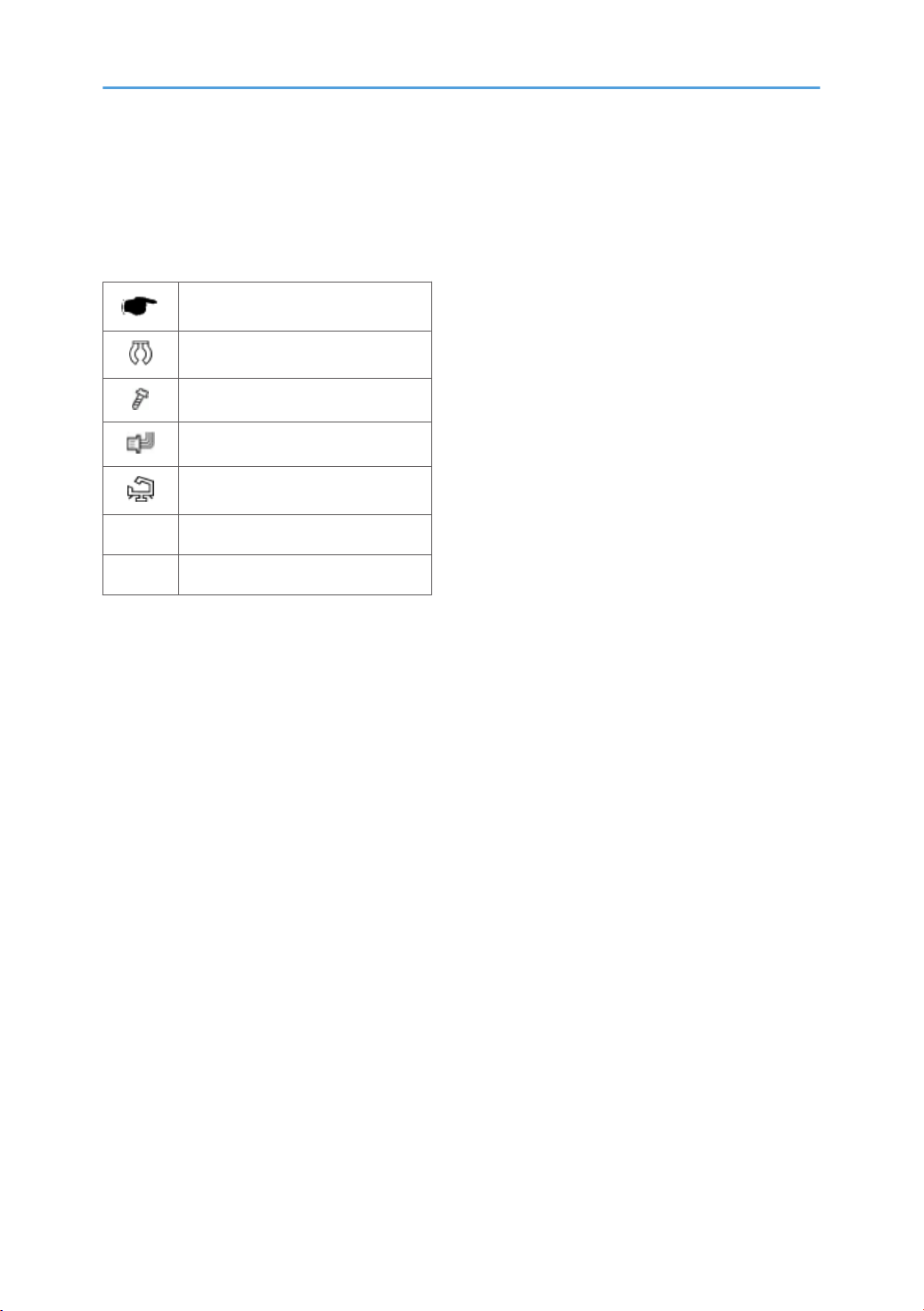
Symbols and Abbreviations
This
manual uses several symbols and abbreviations. The meaning of those symbols and abbreviations are
as follows:
See or Refer to
Clip ring
Screw
Connector
Clamp
SEF Short Edge Feed
LEF Long Edge Feed
4
Page 7

TABLE OF CONTENTS
Safety Precautions..............................................................................................................................................1
To use the machine safely..............................................................................................................................1
Warnings, Cautions, Notes...........................................................................................................................2
Symbols and Abbreviations...............................................................................................................................4
1. Product Information
Specifications....................................................................................................................................................11
Overview..........................................................................................................................................................12
Front View.....................................................................................................................................................12
Rear View.....................................................................................................................................................13
Control Panel................................................................................................................................................
Components.................................................................................................................................................16
Mechanical Components............................................................................................................................17
14
2. Installation
Installation Requirement...................................................................................................................................19
Choosing a Location....................................................................................................................................19
Fax Installation.............................................................................................................................................19
3. Preventive Maintenance
PM Tables.........................................................................................................................................................21
4. Replacement and Adjustment
Transferring Received Fax Data......................................................................................................................23
Operating Procedure...................................................................................................................................
Before You Do..................................................................................................................................................26
Safety Precautions........................................................................................................................................26
Tightening Torque........................................................................................................................................27
Preparation...................................................................................................................................................30
How to Access the Object Component......................................................................................................30
23
Disassembly Flowchart................................................................................................................................31
Common Parts..................................................................................................................................................32
Paper Eject Tray...........................................................................................................................................32
Drum/Toner ASSY.......................................................................................................................................32
Paper Tray....................................................................................................................................................33
Back Cover...................................................................................................................................................34
Rear Chute Cover........................................................................................................................................34
5
Page 8

Document Base ASSY..................................................................................................................................35
Side Cover L.................................................................................................................................................36
Handset Holder (NA/China only).............................................................................................................37
Speaker ASSY..............................................................................................................................................38
Side Cover R/Link Stopper.........................................................................................................................39
Panel Unit......................................................................................................................................................40
Hook PCB ASSY...........................................................................................................................................47
Top Cover.....................................................................................................................................................49
Main Body........................................................................................................................................................62
NCU PCB ASSY...........................................................................................................................................62
Paper Stopper L/S.......................................................................................................................................64
Front Cover...................................................................................................................................................64
Pickup Roller Holder ASSY.........................................................................................................................66
Fixing Unit.....................................................................................................................................................70
High-Voltage PS PCB ASSY........................................................................................................................76
Main PCB.....................................................................................................................................................78
PS PCB Unit/Fan 40....................................................................................................................................79
Laser Unit......................................................................................................................................................83
Sub Chute ASSY..........................................................................................................................................85
Link Lever......................................................................................................................................................86
Tail Edge Actuator.......................................................................................................................................87
Regist Front Actuator/Regist Front Spring.................................................................................................88
Regist Sensor PCB ASSY.............................................................................................................................89
Regist Rear Actuator/Regist Rear Spring...................................................................................................90
Fan Motor 60 Unit.......................................................................................................................................91
Toner LED PCB ASSY/LED Holder.............................................................................................................93
New Toner Actuator/New Toner Actuator Spring...................................................................................94
New Toner Sensor Harness ASSY..............................................................................................................95
Cover Sensor................................................................................................................................................96
Toner Sensor PCB ASSY..............................................................................................................................97
Main Motor ASSY.......................................................................................................................................97
Develop Joint.............................................................................................................................................100
P/R Solenoid ASSY...................................................................................................................................101
6
Page 9

F/R Solenoid ASSY...................................................................................................................................101
Main Frame L.............................................................................................................................................103
Main Frame R............................................................................................................................................104
Harness Routing.............................................................................................................................................106
Laser Unit....................................................................................................................................................106
FG harness ASSY 1/ FG harness ASSY 2/ FG harness ASSY 5.........................................................107
FG harness ASSY......................................................................................................................................108
Regist sensor PCB ASSY............................................................................................................................109
Fan Motor 60 Unit.....................................................................................................................................110
Toner LED PCB ASSY/ Fan 40................................................................................................................111
Toner Sensor PCB ASSY...........................................................................................................................112
P/R Solenoid ASSY/ F/R Solenoid ASSY..............................................................................................113
New Toner Sensor Harness Assy/ Cover Sensor..................................................................................114
Panel Unit...................................................................................................................................................115
Hook PCB...................................................................................................................................................116
Scanning Motor F Sub ASSY...................................................................................................................117
CIS..............................................................................................................................................................118
NCU PCB...................................................................................................................................................119
Requirement Adjustment after Parts Replacement.......................................................................................120
If You Replace the Main PCB...................................................................................................................120
If You Replace the CIS..............................................................................................................................123
If You Replace the Laser Unit....................................................................................................................123
5. Service Maintenance
Entry into the Maintenance Mode................................................................................................................125
List of Maintenance-Mode Functions...........................................................................................................126
User-Access to The Maintenance Mode.....................................................................................................128
Detailed Description of Maintenance-Mode Functions..............................................................................129
EEPROM Parameter Initialization (Function code 01/91)....................................................................129
Printout of Scanning Compensation Data (Function code 05)..............................................................130
ADF Performance Test (Function code 08).............................................................................................131
Test Pattern (Function code 09)................................................................................................................131
Firmware Switch Setting (Function code 10)..........................................................................................132
Printout of Firmware Switch Data (Function code 11)............................................................................136
7
Page 10

Operation Check of LCD (Function code 12).........................................................................................136
Operational Check of Control Panel PCB (Function code 13).............................................................137
Adjustment of Handset Volume (Function code 16)...............................................................................138
Sensor Operational Check (Function code 32).....................................................................................139
Received Data Transfer Function (Function code 53)............................................................................140
Fine Adjustment of Scan Start/End Positions (Function code 54).........................................................142
Acquisition of White Level Data and CIS Scanner Area Setting (Function code 55)..........................143
Continuous Print Test (Function code 67)................................................................................................144
EEPROM Customizing (Function code 74).............................................................................................144
Display of the Equipment's Log Information (Function code 80)...........................................................145
Machine Error Code Indication (Function code 82)..............................................................................147
Output of Transmission Log to the Telephone Line (Function code 87)................................................147
Cancellation of the Memory Security Mode...........................................................................................148
Firmware Installation.....................................................................................................................................149
Installing the Update Data to the Machine.............................................................................................149
Setting ID Codes to Machines..................................................................................................................158
Customizing Codes........................................................................................................................................159
According to Shipping Destination..........................................................................................................159
EEPROM Customizing Codes..................................................................................................................159
Firmware Switches (WSW)...........................................................................................................................160
WSW Switch List.......................................................................................................................................160
WSW01 (Dial pulse setting)....................................................................................................................162
WSW02 (Tone signal setting)..................................................................................................................163
WSW03 (PABX* mode setting)...............................................................................................................164
WSW04 (TRANSFER facility setting)......................................................................................................165
WSW05 (1st dial tone and busy tone detection)..................................................................................166
WSW06 (Redial/Pause key setting and 2nd dial tone detection).......................................................167
WSW07 (Dial tone setting 1)..................................................................................................................170
WSW08 (Dial tone setting 2)..................................................................................................................171
WSW09 (Protocol definition 1)...............................................................................................................172
WSW10 (Protocol definition 2)...............................................................................................................173
WSW11 (Busy tone setting).....................................................................................................................174
WSW12 (Signal detection condition setting).........................................................................................175
8
Page 11

WSW13 (Modem setting)........................................................................................................................176
WSW14 (AUTO ANS facility setting).....................................................................................................177
WSW15 (REDIAL facility setting).............................................................................................................178
WSW16 (Function setting 1)...................................................................................................................179
WSW17 (Function setting 2)...................................................................................................................180
WSW18 (Function setting 3)...................................................................................................................181
WSW19 (Transmission speed setting)....................................................................................................182
WSW20 (Overseas communications mode setting)..............................................................................182
WSW21 (TAD setting 1)..........................................................................................................................184
WSW22 (ECM and call waiting caller ID).............................................................................................184
WSW23 (Communications setting).........................................................................................................185
WSW24 (TAD setting 2)..........................................................................................................................186
WSW25 (TAD setting 3)..........................................................................................................................187
WSW26 (Function setting 4)...................................................................................................................187
WSW27 (Function setting 5)...................................................................................................................188
WSW28 (Function setting 6)...................................................................................................................189
WSW29 (Function setting 7)...................................................................................................................190
WSW30 (Function setting 8)...................................................................................................................190
WSW31 (Function setting 9)...................................................................................................................190
WSW32 (Function setting 10).................................................................................................................191
WSW33 (Function setting 11).................................................................................................................192
WSW34 (Function setting 12).................................................................................................................192
WSW35 (Function setting 13).................................................................................................................193
WSW36 (Function setting 14).................................................................................................................193
WSW37 (Function setting 15).................................................................................................................194
WSW38 (V.34 transmission settings)......................................................................................................195
WSW39 (V.34 transmission speed)........................................................................................................196
WSW40 (V.34 modem settings).............................................................................................................198
WSW41 (ON-duration of the scanning light source)............................................................................199
WSW42 (Internet mail settings)...............................................................................................................200
WSW43 (Function setting 21).................................................................................................................200
WSW44 (Speeding up scanning-1).......................................................................................................201
WSW45 (Speeding up scanning-2).......................................................................................................201
9
Page 12

WSW46 (Monitor of power ON/OFF state and parallel port kept at high)......................................201
WSW47 (Switching between high- and full-speed USB).....................................................................201
WSW48 (USB setup latency)..................................................................................................................201
WSW49 (End-of-copying beep and print in black)..............................................................................201
WSW50 (SDAA settings).........................................................................................................................202
WSW51 (Function setting 16).................................................................................................................202
6. Troubleshooting
Error Indication..............................................................................................................................................203
Troubleshooting Guide..................................................................................................................................204
Introduction................................................................................................................................................204
Precautions.................................................................................................................................................204
Checking Prior to Troubleshooting...........................................................................................................204
Paper Feeding Problems...........................................................................................................................205
Software Setting Problems........................................................................................................................207
Malfunction................................................................................................................................................209
Image Defects............................................................................................................................................216
Incorrect Printout........................................................................................................................................241
Troubleshooting of the Control Panel......................................................................................................243
Troubleshooting of Fax Functions.............................................................................................................245
7. Energy Saving
Energy Save...................................................................................................................................................251
Sleep Modes.............................................................................................................................................251
INDEX...........................................................................................................................................................253
10
Page 13

1. Product Information
1
Specifications
See "Appendices" for the Specifications.
11
Page 14
1. Product Information
1
Overview
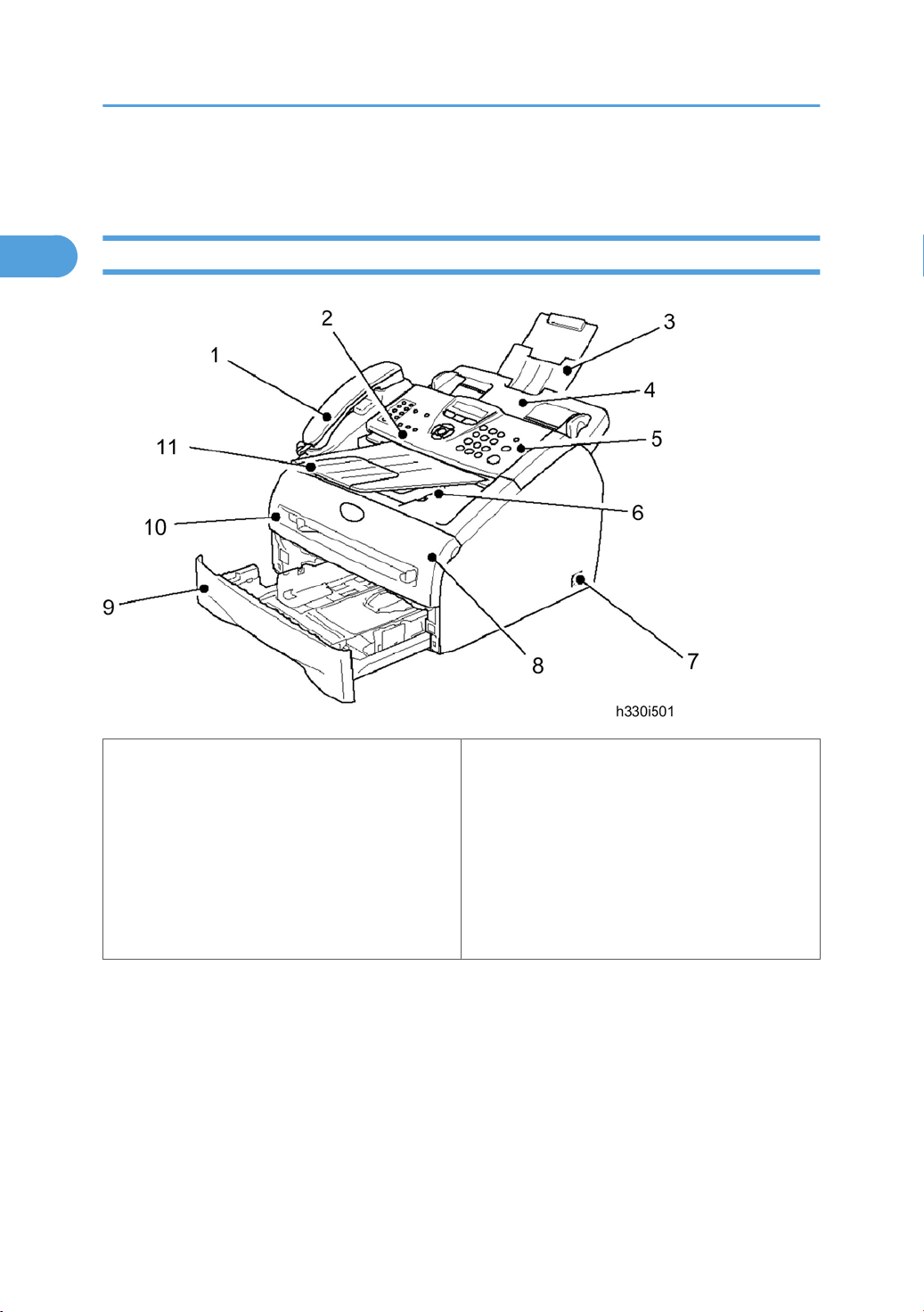
Front View
12
1. Telephone Handset (NA/China only)
2. Control Panel Cover
3. ADF Document Support
4. Automatic Document Feeder (ADF)
5. Control Panel
6. Face-down Output Tray Support Flap with
Extension
7. Power Switch
8. Front Cover
9. Paper Tray
10. Manual Feed Slot
11. ADF Document Output Support
Page 15
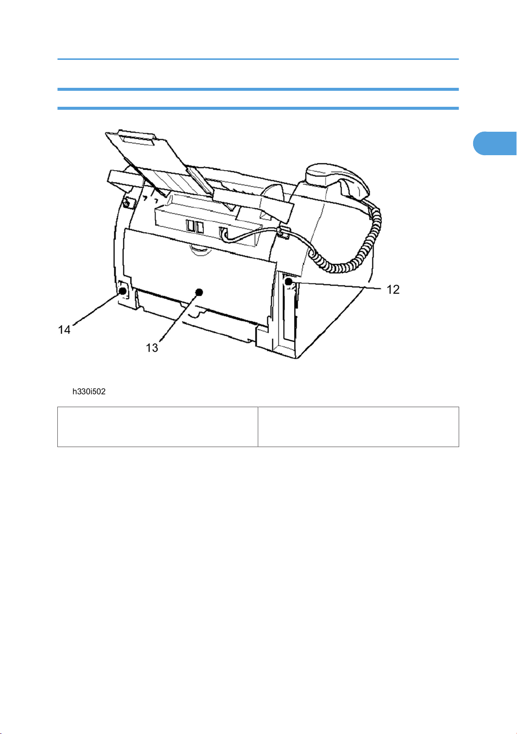
Rear View
1
Overview
12. USB Interface Connector
13. Back Cover
14. AC Power Connector
13
Page 16
1. Product Information
1
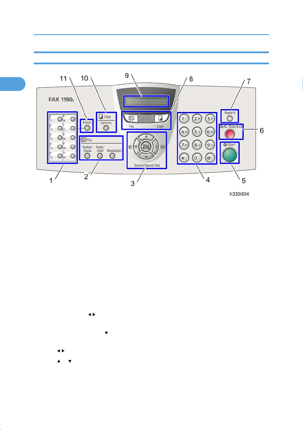
Control Panel
1. One-Touch Keys
These 10 keys give you instant access to 20 previously stored dial numbers.
Fax and Telephone Keys
2.
• Redial/Pause: Redials the last number you called. It also inserts a pause in quick dial numbers.
• Hook/Hold: Lets you dial telephone and fax numbers without lifting the handset.
-OR-
Lets you place telephone calls on hold.
• Resolution: Sets the resolution when you send a fax.
3. Navigation Keys
• Menu/Set: The same key is used for Menu and Set operations. Lets you access the Menu to
program and store your settings in the machine.
• Volume keys (
you can press these keys to adjust the volume.
Search/Speed Dial (
•
lets you dial stored numbers by pressing # and a three-digit number.
• : Press to scroll forward or backward to a menu selection.
• or : Press to scroll through the menus and options.
Dial Pad
4.
): When using the handset, listening to the speaker in Fax mode or on standby,
): Lets you look up numbers that are stored in the dialing memory. It also
Use these keys to dial telephone or fax numbers and as a keyboard for entering information into the
machine.
14
Page 17

Overview
1
The "#" key lets you temporarily switch the dialing mode during a telephone call from Pulse to Tone
(For Canada only).
5. Start: Lets you start sending faxes or making copies.
6. Stop/Exit: Stops an operation or exits from the menu.
7. Reports: Print the Transmission Verification Report, Help List, Quick-Dial List, Fax Journal, and User
Settings.
8. Mode Keys
• Fax: Lets you access Fax mode.
• Copy: Lets you access Copy mode.
9. Liquid Crystal Display (LCD): Displays messages on the screen to help you set up and use your
machine.
10. Copy Key (Temporary settings)
• Options: You can quickly and easily select temporary settings for copying.
11. Shift: To access One-Touch numbers 11 to 20, hold down "Shift" as you press the One-Touch key.
15
Page 18
1. Product Information
1
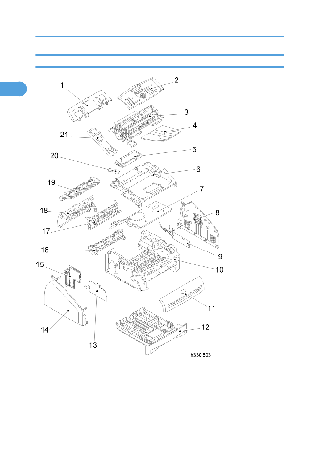
Components
The equipment consists of the following major components:
16
Page 19
Overview
1
1. Document Base ASSY
2. Panel Unit
3. Document Chute ASSY
4. Paper Eject Tray
5. NCU PCB & Shield Case
6. Inner Chute Cover ASSY
7. Laser Unit
8. Side Cover R
9. PS PCB Unit
10. Frame Unit
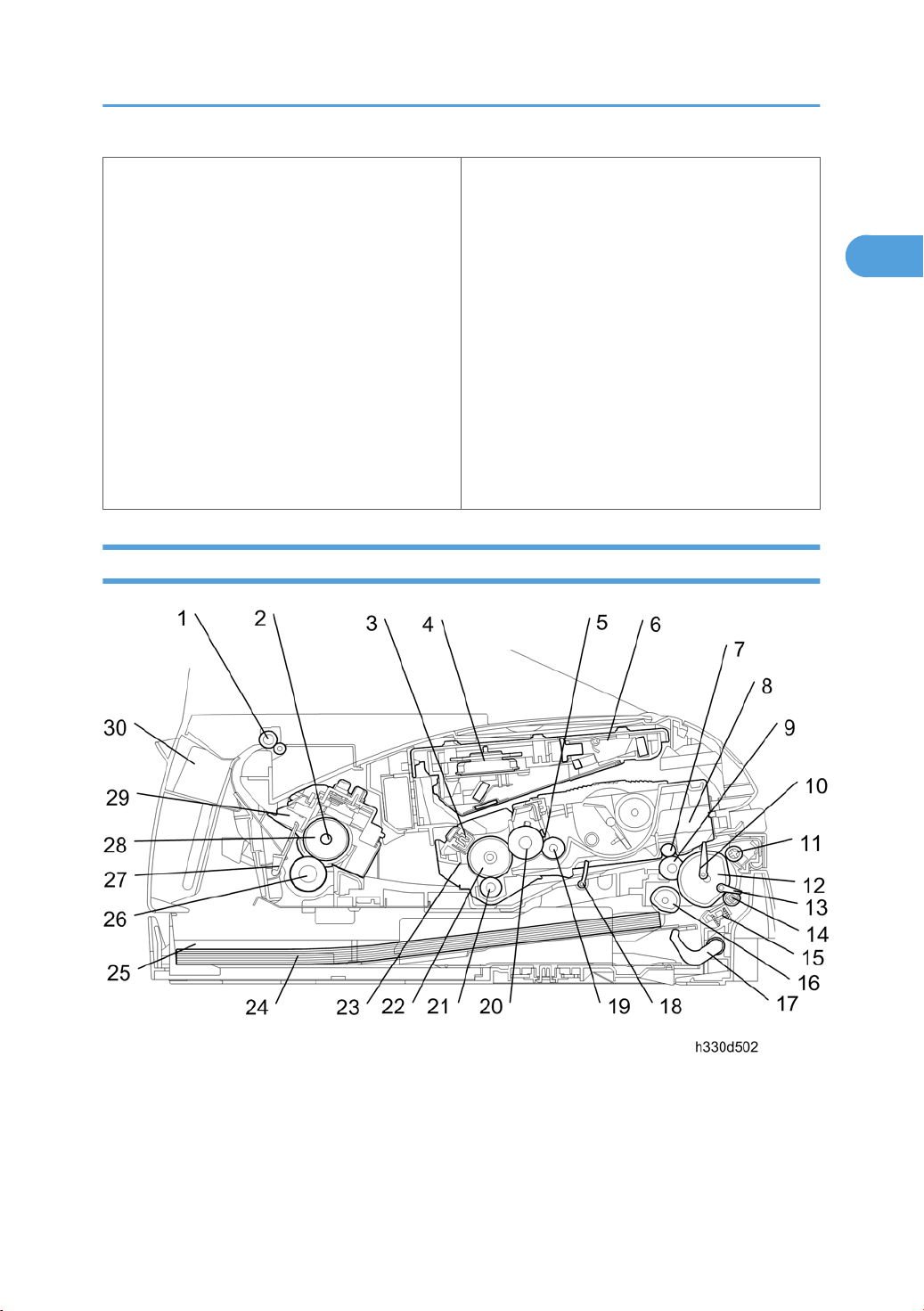
Mechanical Components
11. Front Cover
12. Paper Tray
13. High-voltage PS PCB
14. Side Cover L
15. Main PCB
16. Fixing Unit
17. Rear Chute Cover
18. Back Cover
19. Inner Chute
20. Battery ASSY
21. Handset Holder (NA/China only)
17
Page 20

1. Product Information
1
1. Eject roller ASSY
2. Halogen heater
3. Corona wire
4. Polygon motor
5. Blade
6. Laser unit
7. Pinch roller
8. Drum/toner ASSY
9. Paper feed roller
10. Regist front actuator
11. Pinch roller
12. Separation roller
13. Tail edge actuator
14. Pressure roller
15. Separation pad
16. Feed roller
17. Up plate
18. Regist rear actuator
19. Supply roller
20. Developer roller
21. Transfer roller
22. Exposure drum
23. Brush
24. Paper
25. Paper tray
26. Pressure roller
27. Paper eject actuator
28. Heat roller
29. Fixing unit
30. Back cover
18
Page 21
2. Installation
2
Installation Requirement
Choosing a Location
Place your machine on a flat, stable surface that is free of vibration and shocks, such as a desk.
Put
the machine near a telephone wall jack and a standard, grounded AC power outlet. Choose a location
where the temperature remains between 50°F and 90.5°F (10°C and 32.5°C).
• Avoid placing your machine in a high-traffic area.
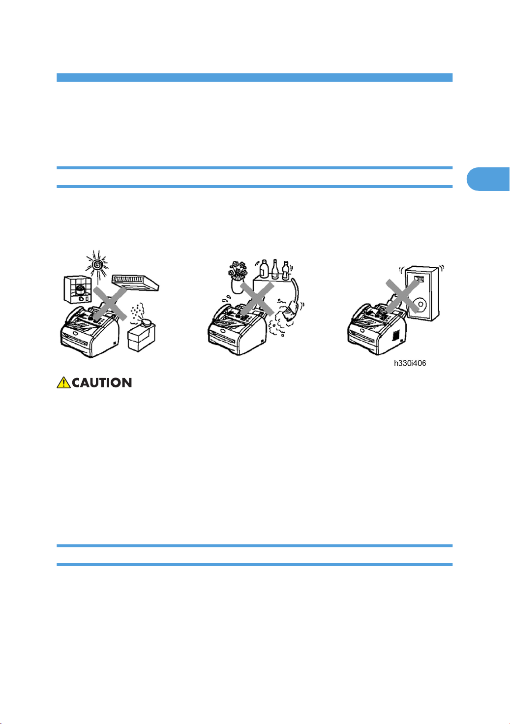
Do not place the machine near heaters, air conditioners, water, chemicals, or refrigerators.
•
• Do not expose the machine to direct sunlight, excessive heat, moisture, or dust.
• Do not connect your machine to an AC power outlet controlled by wall switches or automatic timers.
• Disruption of power can wipe out information in the machine's memory.
• Do not connect your machine to an AC power outlet on the same circuit as large appliances or other
equipment that might disrupt the power supply.
• Avoid interference sources, such as speakers or the base units of cordless phones.
Fax Installation
For details, see the “User’s Guide” of this machine.
19
Page 22

2. Installation
2
20
Page 23

3. Preventive Maintenance
3
PM Tables
There are no PM parts for this machine.
21
Page 24

3. Preventive Maintenance
3
22
Page 25

4. Replacement and Adjustment
4
Transferring Received Fax Data
the machine at the user site requires to be repaired, unplugging the power cord from the wall socket
When
for sending the machine for repair will lose received FAX data if unprinted and left in the machine.
To prevent such data loss, the service personnel should instruct end users (e.g., by telephone) to transfer
data to another facsimile machine using the procedure below.
• The number of files that can be transferred at a time is 99. To transfer 100 files or more, carry out the
following procedure more than one time.
Operating Procedure
1. Connect the machine to be repaired (that has received data in the memory) to the telephone line.
2. Switch the machine on.
3. Press the "Menu/Set", "Start", "Menu/Set", "0", "5" and "3" keys in this order to access useraccessible functions of the maintenance mode.
The "FAX TRANSFER" appears on the LCD.
4. To check the number of received files, press the "1" key.
The "1.NO. OF JOBS" appears on the LCD.
Press the "Menu/Set" key, and the number of received files appears, just as "NO. OF. JOBS:10".
5. To transfer the activity report only, press the "2" key.
The "2.ACTIVITY" appears.
To transfer received files together with the activity report, press the "3" key.
The "3.DOCUMENTS" appears. Note that if there is no received file, the "NO DOCUMENTS"
appears.
6. To transfer the communication list for the latest communication, press the "4" key.
The "4.COM.LIST (NEW)" appears.
To transfer the communication list for last three errors, press the "5" key.
The "5.COM.LIST (ERR3)" appears.
7. With the "2.ACTIVITY", "3.DOCUMENTS", "4.COM.LIST (NEW)" or "5.COM.LIST (ERR3)" being
displayed, press the "Menu/Set" key.
The "ENTER NO. &SET" appears.
8. Enter the telephone number of the receiver machine and press the "Menu/Set" key again.
23
Page 26
4. Replacement and Adjustment
4
sure to type the telephone number with the numerical keys. No one-touch dialing is allowed in this
• Be
procedure.
• The machine displays the "ACCEPTED" for approx. two seconds and starts dialing to transfer data.
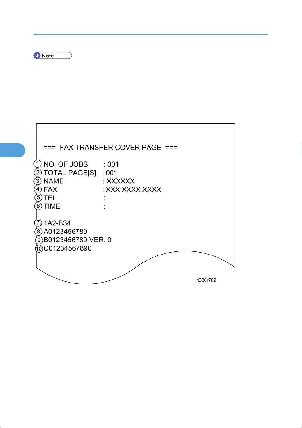
• No station ID will be attached. A cover page and end page as shown below will be automatically
attached, instead.
Cover page sample
1. Job number
2.
3. Station ID registered in the sender equipment
4. Fax number of the sender equipment
5. Telephone number of the sender equipment
6. Transfer start date
7. Model code
8. Boot ROM information
9. ROM information
10. Serial number
24
Total number of pages to be transferred
Page 27
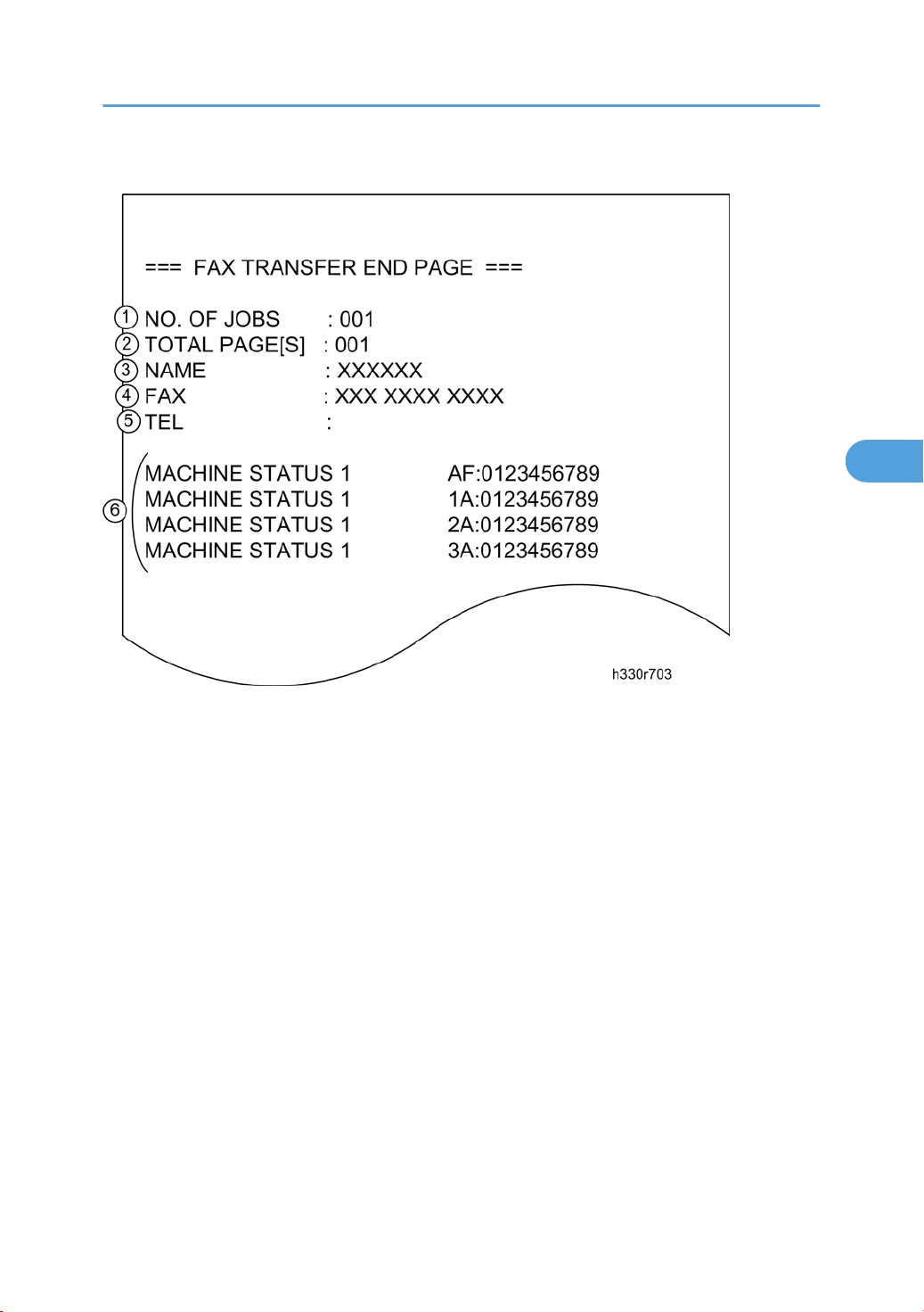
End page sample
4
Transferring Received Fax Data
1. Job number
2.
Total number of pages to be transferred
3. Station ID registered in the sender equipment
4. Fax number of the sender equipment
5. Telephone number of the sender equipment
6. Error codes
25
Page 28

4. Replacement and Adjustment
4
Before You Do
Safety Precautions
To prevent the creation of secondary problems by mishandling, observe the following precautions during
maintenance work.
1. Before starting disassembly/reassembly jobs, unplug the power cord and telephone line. In particular,
when having access to the power supply inside the machine, make sure that the power cord is
unplugged from the electrical outlet; when having access to the main PCB or NCU PCB, make sure
that both the power cord and telephone line are unplugged from the machine.
2. Be careful not to lose screws, washers, or other parts removed for parts replacement.
3. When using soldering irons and other heat-generating tools, take care not to damage the resin parts
such as wires, PCBs, and covers.
4. Static electricity charged in your body may damage electronic parts. When transporting PCBs, be
sure to wrap them in conductive sheets.
5. When replacing the PCB and all the other related parts, put on a grounding wrist band and perform
the job on a static mat. Also take care not to touch the conductor sections on the flat cables or on the
wire harness.
6. Be sure to reinsert self-tapping screws correctly, if removed.
7. Tighten screws to the torque values listed on the next page.
8. After disconnecting flat cables, check that each cable is not damaged at its end or shortcircuited.
9. When connecting flat cables, do not insert them at an angle. After insertion, check that the cables are
not at an angle.
10. When connecting or disconnecting cable connectors, hold the connector bodies not the wires. If the
connector has a lock, always slide the connector lock to unlock it.
11. Before reassembly, apply the specified lubricant to the specified points.
(Refer to Section 5.2 in this chapter.)
12. After repairs, check not only the repaired portion but also that the connectors and other related
portions function properly before operation checks.
13. After you use the machine, some internal parts are extremely HOT! To prevent injuries, be careful not
to put your fingers in the areas shown in the illustration.
26
Page 29

Tightening Torque
4
Before You Do
Location of screw Screw type Q'ty
Document base ASSY Taptite, cup B M4x12 2 0.79 ±0.1 (8 ±1)
Side cover L Taptite, bind B M4x12 2 0.79 ±0.1 (8 ±1)
Speaker hold spring Taptite, cup B M3x8 1 0.49 ±0.1 (5 ±1)
Side cover R Taptite, bind B M4x12 2 0.79 ±0.1 (8 ±1)
Location of screw Screw type Q'ty
ADF plate spring Taptite, cup B M3x6 1 0.49 ±0.1 (5 ±1)
Panel rear cover Taptite, cup B M3x8 3 0.46 ±0.05 (4.5 ±0.5)
Rear cover stopper Taptite, bind B M4x12 1 0.79 ±0.1 (8 ±1)
Inner chute Taptite, bind B M4x12 2 0.79 ±0.1 (8 ±1)
LV shield plate cover
Screw, pan (s/p washer)
M3.5x6
1 0.49 ±0.1 (5 ±1)
Tightening torque
N•m (kgf•cm)
Tightening torque
N•m (kgf•cm)
Top cover ASSY Taptite, bind B M4x12 2 0.79 ±0.1 (8 ±1)
LF ground plate Taptite, cup S M3x6 1 0.69 ±0.1 (7 ±1)
LF FG harness ASSY Taptite, cup B M3x4 1 0.39 ±0.1 (4 ±1)
Inner chute cover ASSY Taptite, bind B M4x12 4 0.79 ±0.1 (8 ±1)
Scanning driver ASSY Taptite, cup B M3x8 2 0.49 ±0.1 (5 ±1)
Scanning motor F sub ASSY
NCU FG harness
NCU unit Taptite, bind B M4x12 2 0.78 ±0.1 (8 ±1)
NCU PCB ASSY Taptite, cup S M3x6 2 0.49 ±0.1 (5 ±1)
Screw, pan (s/p washer)
M3x6
Screw, pan (s/p washer)
M3.5x6
1 0.69 ±0.1 (7 ±1)
1 0.49 ±0.1 (5 ±1)
27
Page 30

4. Replacement and Adjustment
4
Location of screw Screw type Q'ty
Chute base Taptite, bind B M4x12 6 0.8 ±0.1 (8 ±1)
Location of screw Screw type Q'ty
Fixing unit Taptite, cup B M4x12 2 0.78 ±0.1 (8 ±1)
Halogen heater
Thermistor ASSY Taptite, cup B M3x12 1 0.59 ±0.1 (6 ±1)
Location of screw Screw type Q'ty
High voltage PS PCB
CDCC PCB Screw, Pan M3x6 2 0.49 ±0.1 (5 ±1)
Screw, pan (s/p washer)
M3x8
Taptite, bind B M4x12
Taptite, cup S M3x6
2 0.59 ±0.05 (6 ±0.5)
2
2
Tightening torque
N•m (kgf•cm)
Tightening torque
N•m (kgf•cm)
Tightening torque
N•m (kgf•cm)
0.78 ±0.1 (8 ±1)
0.69 ±0.1 (7 ±1)
28
Main PCB Taptite, cup S M3x6 5 0.69 ±0.1 (7 ±1)
FG harness ASSY 1
LV shield plate cover Taptite, cup S M3x6 2 0.69 ±0.1 (7 ±1)
LV shield plate
AC holder Taptite, bind B M4x12 1 0.59 ±0.1 (6 ±1)
PS PCB unit Taptite, cup S M3x6 2 0.69 ±0.1 (7 ±1)
Location of screw Screw type Q'ty
Laser unit Taptite, cup S M3x6 4 0.69 ±0.1 (7 ±1)
FG harness ASSY 6 Taptite, cup S M3x6 1 0.69 ±0.1 (7 ±1)
Screw, pan (S/P washer)
M3.5x6
Taptite, bind B M4x12
Screw, pan (s/p washer)
M3.5x6
1 0.59 ±0.1 (6 ±1)
2
1
0.78 ±0.1 (8 ±1)
0.59 ±0.1 (6 ±1)
Tightening torque
N•m (kgf•cm)
Page 31

Before You Do
4
Location of screw Screw type Q'ty
Air duct Taptite, cup S M3x6 2 0.69 ±0.1 (7 ±1)
Location of screw Screw type Q'ty
Sub chute ASSY Taptite, bind B M4x12 2 0.78 ±0.1 (8 ±1)
Location of screw Screw type Q'ty
Regist sensor PCB ASSY Taptite, bind B M3x6 1 0.39 ±0.1 (4 ±1)
Location of screw Screw type Q'ty
Base plate Taptite, bind B M4x12 3 0.78 ±0.1 (8 ±1)
Tightening torque
N•m (kgf•cm)
Tightening torque
N•m (kgf•cm)
Tightening torque
N•m (kgf•cm)
Tightening torque
N•m (kgf•cm)
Location of screw Screw type Q'ty
Toner sensor PCB ASSY Taptite, cup B M3x6 1 0.25 ±0.05 (2.5 ±0.5)
Location of screw Screw type Q'ty
Main shield plate Taptite, bind B M4x12 4 0.78 ±0.1 (8 ±1)
Gear plate calking ASSY Taptite, bind B M4x12 3 0.78 ±0.1 (8 ±1)
Main motor ASSY Taptite, cup S M3x6 3 0.69 ±0.1 (7 ±1)
P/R solenoid ASSY Taptite, bind B M3x10 1 0.49 ±0.1 (5 ±1)
F/R solenoid ASSY Taptite, bind B M3x10 1 0.49 ±0.1 (5 ±1)
Main frame L Taptite, bind B M4x12 2 0.78 ±0.1 (8 ±1)
Tightening torque
N•m (kgf•cm)
Tightening torque
N•m (kgf•cm)
29
Page 32

4. Replacement and Adjustment
4
Location of screw Screw type Q'ty
Main frame R Taptite, bind B M4x12 3 0.78 ±0.1 (8 ±1)
Tightening torque
N•m (kgf•cm)
Preparation
Prior to proceeding with the disassembly procedure,
Unplug
1.
- the modular jack of the telephone line,
- the USB cable, if connected (not shown below), and
- the modular jack of the external telephone set if connected (not shown below).
How to Access the Object Component
On the next page is a disassembly flowchart which helps you access the object components. To remove
fixing unit, for example, first find it on the flowchart and note its name ("Fixing Unit"). To access it, you
the
need to remove all the parts above the fixing unit on the flowchart ("Back Cover"
"Side Cover R/Link Stopper" "Top Cover") before the unit itself can be removed.
"Rear Chute Cover"
otherwise specified, all parts should be replaced in the reverse order to which they were removed
Unless
to reassemble the machine.
30
Page 33

Disassembly Flowchart
4
Before You Do
31
Page 34

4. Replacement and Adjustment
4
Common Parts
Paper Eject Tray
1. Remove the paper eject tray [A].
Drum/Toner ASSY
32
Page 35

1. Open the front cover [A] and remove the drum/toner ASSY [B].
4
Paper Tray
Common Parts
1. Close the front cover [A] and pull out the paper tray [B].
2.
Remove the paper from the paper tray.
3. Remove the separation pad holder ASSY [A] and the separation pad spring [B].
4.
Use a screwdriver [C] to release the hook [D].
33
Page 36

4. Replacement and Adjustment
4
Back Cover
1. Paper Exit Tray ( p.32)
2. Drum/Toner ASSY ( p.32)
3. Paper Tray ( p.33)
4. Remove the section [A] of the back cover while opening the back cover slightly.
5.
Remove the back cover [B].
Rear Chute Cover
1. Back Cover ( p.34)
34
Page 37

2. Remove the rear chute cover [A].
4
Common Parts
3. Remove the paper eject actuator [A] and the eject actuator spring [B].
Document Base ASSY
1. Paper Exit Tray ( p.32)
2.
Drum/Toner ASSY (
3.
Paper Tray (
p.33)
p.32)
35
Page 38

4. Replacement and Adjustment
4
4. Remove the two screws (cup B M4x12) [A] to remove the document base ASSY [B].
Side Cover L
1. Document Base ASSY ( p.35)
2. Open the front cover [A].
3.
Remove the side cover L [B] (
x 2: B M4x12).
36
Page 39

4. Disconnect the connector [A] of the speaker ASSY.
4
Handset Holder (NA/China only)
Common Parts
1. Top Cover ( p.49)
2. Open the panel unit [A] and remove the link stopper [B].
37
Page 40

4. Replacement and Adjustment
4
3. Release the four hooks to remove the handset holder [A].
Speaker ASSY
1. Side Cover L ( p.36)
2. Remove the speaker hold spring [A] and speaker ASSY [B] ( x 1; B M3x8).
38
Page 41

Side Cover R/Link Stopper
4
1. Side Cover L ( p.36)
Common Parts
2. Remove the side cover R [A] ( x 2; B M4x12, hooks).
3. Remove the link stopper [A] from the top cover [B].
39
Page 42

4. Replacement and Adjustment
4
Panel Unit
1. Handset Holder ( p.37)
40
2. Disconnect the panel harness [A].
3.
Remove the panel unit [B].
Page 43

Common Parts
4
4. Remove
the separation rubber [A], ADF plate spring [B] and front plate spring [C] (
x 1; B M3x6).
41
Page 44

4. Replacement and Adjustment
4
5. Remove the actuator R [A] from the panel unit [B].
42
Page 45

Common Parts
4
6. Release the four hooks to remove the panel rear cover [A] ( x 3; B M3x8).
43
Page 46

4. Replacement and Adjustment
4
7. Remove the actuator F [A] from the panel rear cover [B].
8. Disconnect the LCD harness [A].
• After disconnecting flat cable(s), check that each cable is not damaged at its end or shortcircuited.
When connecting flat cable(s), do not insert them at an angle. After insertion, check that the
•
cables are not at an angle.
44
Page 47

9. Release the three hooks to remove the panel PCB ASSY [A].
4
Common Parts
10. Release the two hooks to remove the panel PCB ASSY [A].
45
Page 48

4. Replacement and Adjustment
4
11. Remove the rubber key [A].
46
Page 49

12. Release the two hooks to remove the back light holder [A].
4
13. Remove the back light film [A].
14.
Release the one hook to remove the LCD [B].
Common Parts
Hook PCB ASSY
1. Handset Holder ( p.37)
47
Page 50

4. Replacement and Adjustment
4
48
2. Disconnect the connector [A] of the hook PCB ASSY [B].
3.
Release the one hook to remove the hook PCB ASSY [B].
4. Remove the actuator hook [A] from the hook PCB ASSY [B].
Page 51

Top Cover
4
1. Rear Chute Cover ( p.34)
Common Parts
2. Remove the rear cover stopper [A] ( x 1; B M4x12).
49
Page 52

4. Replacement and Adjustment
4
3. Remove the inner chute [A] ( x 2; B M4x12, spring x 1).
• Re-assemble the inner chute [A] while pushing onto the pinch roller [B] of the inner chute with
the eject roller [C] of the top cover [D].
4. Disconnect the three connectors from the main PCB [A].
50
Page 53

5. Remove the the NCU FG harness ASSY [A] ( x 1; pan (S/P washer) M3.5x6).
4
Common Parts
6. Disconnect the connector [A] of the battery.
7.
Release the one hook to remove the battery [B].
• There is a danger of explosion if the battery is incorrectly replaced.
51
Page 54

4. Replacement and Adjustment
4
• Use a genuine spare part when you replace the battery.
• Do not disassemble, recharge or dispose of in fire.
• Used battery should be disposed of according to local regulations.
8. Disconnect the battery harness from the main PCB [C].
52
9. Release the six hooks to remove the top cover [A] ( x 2; B M4x12).
Page 55

Common Parts
4
10. Remove the paper eject roller ASSY [A] from the top cover [B].
• When
removing the paper eject roller ASSY, the spacer may come off easily. Be sure not to lose
it.
53
Page 56

4. Replacement and Adjustment
4
11. Remove the LF ground plate [A] ( x 1; S M3x6).
12. Release the two hooks to remove the bushing 5 [A].
54
Page 57

13. Remove the document ejection roller ASSY [B].
4
Common Parts
14. Release the hook to remove the pressure roller ASSY [A].
15. Remove the two pressure rollers [A] from the pressure roller shaft [B].
55
Page 58

4. Replacement and Adjustment
4
16. Remove the LF spring [A] from the top cover [B].
17. Release the two hooks to remove the bushing 5 [A].
18.
Remove the LF roller [B].
56
Page 59

19. Remove the scanning drive LF FG harness ASSY [A] ( x 1; B M3x4).
4
Common Parts
20. Remove the four bind taptite screws.
21. Release
(
the four hooks to remove the document chute ASSY [A] from the inner chute cover ASSY [B]
x 1; B M4x12).
57
Page 60

4. Replacement and Adjustment
4
22. Remove the CIS [A].
23. Disconnect the CIS harness [A].
58
Page 61

Common Parts
4
24. Remove the two CIS springs [A].
25. Remove the LF roller gear [A].
59
Page 62

4. Replacement and Adjustment
4
26. Remove the separation roller [A].
27. Remove the scanning driver ASSY [A] ( x 2; B M3x8).
60
Page 63

28. Remove the scanning motor F sub ASSY [A] ( x 1; M3x6).
4
Common Parts
61
Page 64

4. Replacement and Adjustment
4
Main Body
NCU PCB ASSY
1. Paper Eject Roller ASSY ( p.49 "Top Cover")
2. Remove the NCU FG harness ASSY [A] ( x 1; pan (S/P washer) M3.5x6).
62
Page 65

Main Body
4
3. Remove the scanning drive LF FG harness [A] and NCU unit [B] ( x 2; B M4x12).
4. Turn the NCU unit upside down.
5.
Remove the NCU PCB ASSY [A] (
6.
Disconnect the NCU harness ASSY [B].
x 2; S M3x6).
63
Page 66

4. Replacement and Adjustment
4
Paper Stopper L/S
1. Remove the paper stopper ASSY [A] from the inner chute cover ASSY [B].
2. Remove the paper stopper S [A] from the paper stopper L [B].
Front Cover
1. Paper Exit Tray ( p.32)
64
Page 67

2. Drum/Toner ASSY ( p.32)
4
3. Paper Tray ( p.33)
Main Body
4. Release the hook [A] of the drive release cam from the front cover ASSY [B].
5. Release the hook [A] on the front cover ASSY from the chute [B].
6.
Slide the front cover ASSY to the direction of the arrow shown in the figure above to remove it.
65
Page 68

4. Replacement and Adjustment
4
Pickup Roller Holder ASSY
1. Side Cover L ( p.36)
66
2. Turn the printer upside down.
•
Printer top side [A]
3. Remove the chute base [B] (
• When
re-assembling the chute base, check that the screws [C] are secured correctly. For details,
see "How to check" described below.
x 6; B M4x12).
Page 69

Main Body
4
4. Remove the spring extension P/R [A] from the gear 52 P/R [B].
5.
Release the hook and remove the gear 52 P/R [B].
67
Page 70

4. Replacement and Adjustment
4
6. Remove the bush F/R [A].
7.
Remove the F/R roller shaft ASSY [B].
8. Remove the link lever [A] from the hook of the pickup roller holder ASSY [B].
9.
Remove the pickup roller holder ASSY [B].
68
Page 71

• The
4
[B]. Be careful not to lose the spring [A].
How to check
Main Body
pickup roller holder spring [A] is assembled on the bottom of the pickup roller holder ASSY
Check that the distance [A] between the floor [B] and the separation roller collar [C] of the pickup roller
holder ASSY is 45.5 to 47.5mm by using the plate jig [D]. If not, re-assemble the chute base.
69
Page 72

4. Replacement and Adjustment
4
• [E] (height: 47.5 mm) which is contacted with the roller is acceptable.
•
[G] (more than 47.5 mm) which is not contacted with the roller is NOT acceptable.
• [F] (height: 45.5 mm) which is not contacted with the roller.
• [H] (less than 45.5 mm) which is contacted with the roller is NOT acceptable.
Fixing Unit
1. Side Cover R/Link Stopper ( p.39)
70
Page 73

Main Body
4
2. Disconnect the heater harness connector [A] and thermistor harness connector [B].
3.
Remove the fixing unit [C] (
• Be sure not to touch the pressure roller.
x 2; B M4x12).
71
Page 74

4. Replacement and Adjustment
4
4. Remove the two PR springs [A].
5. Remove
[D].
6. Remove the two PR arm ASSYs [A] and two PR bushes [B] from the pressure roller [C].
the pressure roller ASSY (pressure roller [B], PR arm ASSY [C], PR bush) from the fuser frame
72
Page 75

Main Body
4
7. Release each hook of the springs [A] from the fuser frame [B] and remove the four separate claw
ASSYs [C].
•
Align the separate claw ASSY with the shape of the fuser frame to remove.
• Be careful not to damage the heat roller [D] when removing the separate claw ASSYs [C]
73
Page 76

4. Replacement and Adjustment
4
8. Remove the heat roller [A] ( x 2; pan (S/P washer) M3x8).
9.
Remove the halogen heater [B].
• When re-assembling the heat roller [A], assemble the HR bush [B] onto the fuser frame [C]
referring to the figure above.
74
Page 77

Main Body
4
• When
10. Remove the HR gear [A].
Remove the two HR bushes [B].
11.
• Return the hooks [C] to the original position.
re-assembling the halogen heater [A], put the halogen heater [A] onto the fuser frame [B]
so that the terminal of the heater harness [C] is at the top, and secure the screws in the order
shown in the figure above.
75
Page 78

4. Replacement and Adjustment
4
12. Remove the thermistor ASSY harness[A] from the four hooks.
13.
Remove the thermistor ASSY [B] (
• When re-assembling the thermistor ASSY [A] to the fuser frame [B], ensure the direction of the
thermistor ASSY [A] is correct referring to the figure above;
x 1; B M3x12).
High-Voltage PS PCB ASSY
1. Side Cover R/Link Stopper ( p.39)
76
Page 79

2. Disconnect the three connectors [A] from the high-voltage PS PCB ASSY [B].
4
3. Disconnect the high-voltage PS PCB harness [C] from the main PCB.
• After disconnecting flat cable(s), check that each cable is not damaged at its end or shortcircuited.
Main Body
When connecting flat cable(s), do not insert them at an angle. After insertion, check that the
•
cables are not at an angle.
4. Remove the high-voltage PS PCB [A] from main frame L [B]. (Top x 2; B M4x12, Bottom x 2; S
M3x6, hook)
77
Page 80

4. Replacement and Adjustment
4
Main PCB
1. Side Cover R/Link Stopper ( p.39)
2. Disconnect all connectors from the main PCB [A].
• After disconnecting flat cable(s), check that each cable is not damaged at its end or shortcircuited.
When connecting flat cable(s), do not insert them at an angle. After insertion, check that the
•
cables are not at an angle.
78
Page 81

Main Body
4
3. Remove the FG harness ASSY 6 [A] ( x 5; S M3x6).
4.
Remove the main PCB [B] from main frame L [C].
• When replacing the main PCB [B], refer to "Adjustments and Updating of Settings, Required
After Parts Replacement".
After disconnecting flat cable(s), check that each cable is not damaged at its end or short-
•
circuited.
• When connecting flat cable(s), do not insert them at an angle. After insertion, check that the
cables are not at an angle.
PS PCB Unit/Fan 40
1. Side Cover R/Link Stopper ( p.39)
79
Page 82

4. Replacement and Adjustment
4
2. Remove the duct film [A].
3.
Remove the FG harness ASSY 1 [B] (
4. Remove the LV shield plate cover [A] from the main frame R [B] ( x 2; S M3x6, x 1; pan (S/P
washer) M3.5x6).
x 1; pan (S/P washer) M3.5x6).
80
Page 83

Main Body
4
5. Remove the LV insulation sheet [A].
6. Remove the ground wire [A] ( x 1; pan (S/P washer) M3.5x6).
7.
Remove the AC holder [B] (
8.
Remove the two bind B M4x12, taptite screws and then remove the LV shield plate [C] (
M4x12).
x 1; B M4x12).
x 2; B
81
Page 84

4. Replacement and Adjustment
4
• Re-assemble the ground wire [A] so that the section attached to the terminal is downwards.
9. Remove the two cup S M3x6 taptite screws.
Disconnect the four connectors from the PS PCB unit [A], and then remove the PS PCB unit [A].
10.
11. Remove the power supply switch [B] from the LV shield plate [C].
82
Page 85

Main Body
4
• When disconnecting the connectors, disconnect the regist sensor PCB connector [A] and toner
LED PCB unit ASSY connector [B] first, lift up the PS PCB unit [C] from the LV shield plate, and
disconnect the two connectors of the main PCB [D] and fan 40 [E].
12. Remove the Fan 40 [A].
• When re-assembling the fan 40 unit, make sure to turn the side with a label [B] outwards.
Laser Unit
1. Sub Chute ASSY ( p.85)
83
Page 86

4. Replacement and Adjustment
4
2. Remove the FG harness ASSY 6 [A] ( x 1; S M3x6).
3.
Remove the laser unit [B] (
4. Remove the filter ASSY [A] from the air duct [B].
5.
Remove the air duct [B] (
x 4; S M3x6).
x 1; S M3x6).
84
Page 87

Main Body
4
• When
• [C]: 2 to 3 mm/ [D]: 1 to 2 mm
• Another barcode label supplied with a new unit is spare. Make sure to throw it out.
replacing the laser unit, replace the barcode label [A] attached on the gear plate calking
ASSY [B] with a new one supplied with a new unit.
Sub Chute ASSY
1. Top Cover ( p.49)
85
Page 88

4. Replacement and Adjustment
4
2. Remove the sub chute ASSY [A] ( x 2; B M4x12).
Link Lever
1. Pickup Roller Holder ASSY ( p.66)
86
Page 89

2. Turn the printer body upside down.
4
• [A]: Printer top side
3. Pull the section [B] outwards and remove the link lever [C].
Main Body
• When re-assembling the link lever [A], insert the end of the link lever [A] into the main frame L
[B] referring to the figure above.
Tail Edge Actuator
1. Pickup Roller Holder ASSY ( p.66)
87
Page 90

4. Replacement and Adjustment
4
2. Remove the tail edge actuator [A] with the tail edge spring [B].
3.
Remove the tail edge spring [B] from the tail edge actuator.
• [C]: Printer top side
Regist Front Actuator/Regist Front Spring
1. Pickup Roller Holder ASSY ( p.66)
88
Page 91

2. Remove the regist front actuator [A] with the regist front spring [B].
4
Main Body
3.
Remove the regist front spring [B] from the regist front actuator.
• [C]: Printer top side
Regist Sensor PCB ASSY
1. Regist Front Actuator/Regist Front Spring ( p.88)
89
Page 92

4. Replacement and Adjustment
4
2. Release the harness from the hook and remove the regist sensor PCB ASSY [A] ( x 1; B M3x6).
• [B]: Printer top side
Regist Rear Actuator/Regist Rear Spring
1. Pickup Roller Holder ASSY ( p.66)
90
Page 93

2. Remove the regist rear spring [A].
4
Main Body
3.
Remove the regist rear actuator [B].
• [C]: Printer top side
Fan Motor 60 Unit
1. PS PCB Unit/Fan 40 ( p.79)
91
Page 94

4. Replacement and Adjustment
4
2. Remove
1 each; B M4x12).
3.
Remove the base plate [D].
the three bind B M4x12, taptite screws and three FG harness ASSY 1 [A], 4 [B], 5 [C] (
• [E]: Printer top side
x
92
Page 95

Main Body
4
4. Release
[B].
the harness from the hook, and then remove the fan motor 60 unit [A] from the main frame R
• When re-assembling the fan motor 60 unit [A], make sure to turn the side with a label [C]
outwards.
Toner LED PCB ASSY/LED Holder
1. Fan Motor 60 Unit ( p.91)
93
Page 96

4. Replacement and Adjustment
4
2. Remove the toner LED PCB ASSY [A] from the main frame R [B].
3.
Remove the LED holder [C] from the toner LED PCB ASSY [D].
New Toner Actuator/New Toner Actuator Spring
1. Laser Unit ( p.83)
94
Page 97

Main Body
4
2. Remove the new toner actuator spring [A].
3.
Release the hook and remove the new toner actuator [B] from the main frame L [C].
New Toner Sensor Harness ASSY
1. High-Voltage PS PCB ASSY ( p.76)
95
Page 98

4. Replacement and Adjustment
4
2. Release
the two hooks and remove the new toner sensor harness ASSY [A] from the main frame L [B].
Cover Sensor
1. New Toner Sensor Harness ASSY ( p.95)
2. Release the two hooks and remove the cover sensor [A] from the main frame L [B].
96
Page 99

Toner Sensor PCB ASSY
4
1. Cover Sensor ( p.96)
Main Body
2. Remove the toner sensor PCB ASSY [A] ( x 1; B M3x6).
Main Motor ASSY
1. High-Voltage PS PCB ASSY ( p.76)
97
Page 100

4. Replacement and Adjustment
4
2. Remove the main PCB sheet [A].
3.
Remove the FG harness ASSY 4 [B], and then remove the main shield plate [C] (
x 4; B M4x12).
98
 Loading...