

Ricoh FAX2700L SPECIFICATIONS PIF130

PRINTER INTERFACE
PIF130
FIELD SERVICE MANUAL
1. OVERALL IN FORMATION
1.1. CONTROLLER SPECIFICATIONS
Item Specifications
Resolution 300 x 300 dpi
RAM Capacity 1.0 MB (Standard)
Upgradable to 2, 3, or 5 MB
Emul ation Standard:
HP LaserJet 4L
ESC/P
ESC/P
HP GL/2
Opti onal:
PostScrip t
Resident Fonts 21 scalable fonts and 3 bitmap fonts
(Refer to the Operator’s Manual for additional
information.)
Paper Size
Note: All the acceptable sizes
must be in portrait orientation.
Host Interface Standard:
A4
A5
B5
LT (Letter)
HLT (Half letter)
LGL (Legal )
GLT (Government letter)
GLG (Government legal)
EXE (Executive)
F4
MON (Monarch)
C10 (Commercial 10)
DL
C5
IB5 (International B5)
C6
Bi-Centronics
Optional:
LocalTalk
®
24-pin printer emulation (LQ ® mode)
®
9-pin printer emulation (LX ® mode)
TM
emulation (LJ4L mode)
TM
emulation (EPSON GL/2 ® mode)
TM
Level 2
TM
parallel interface x 1
TM
Interface x 1
1.2. ENGINE SPECIFICATIONS
Item Specifications
Resolution 300 x 300 dpi
Print Speed (Engine Speed) Up to 10 ppm (Letter or A4)
Warm-up Time 20 seconds or les s at normal temperatur e
Paper Size The available paper sizes are not the same as those
available with the controller. The selected paper size
depends on the machine’s hardware specifications.
Refer to the Operator’s Manual for addi tional
information.
PIF13 0 1-1 SM
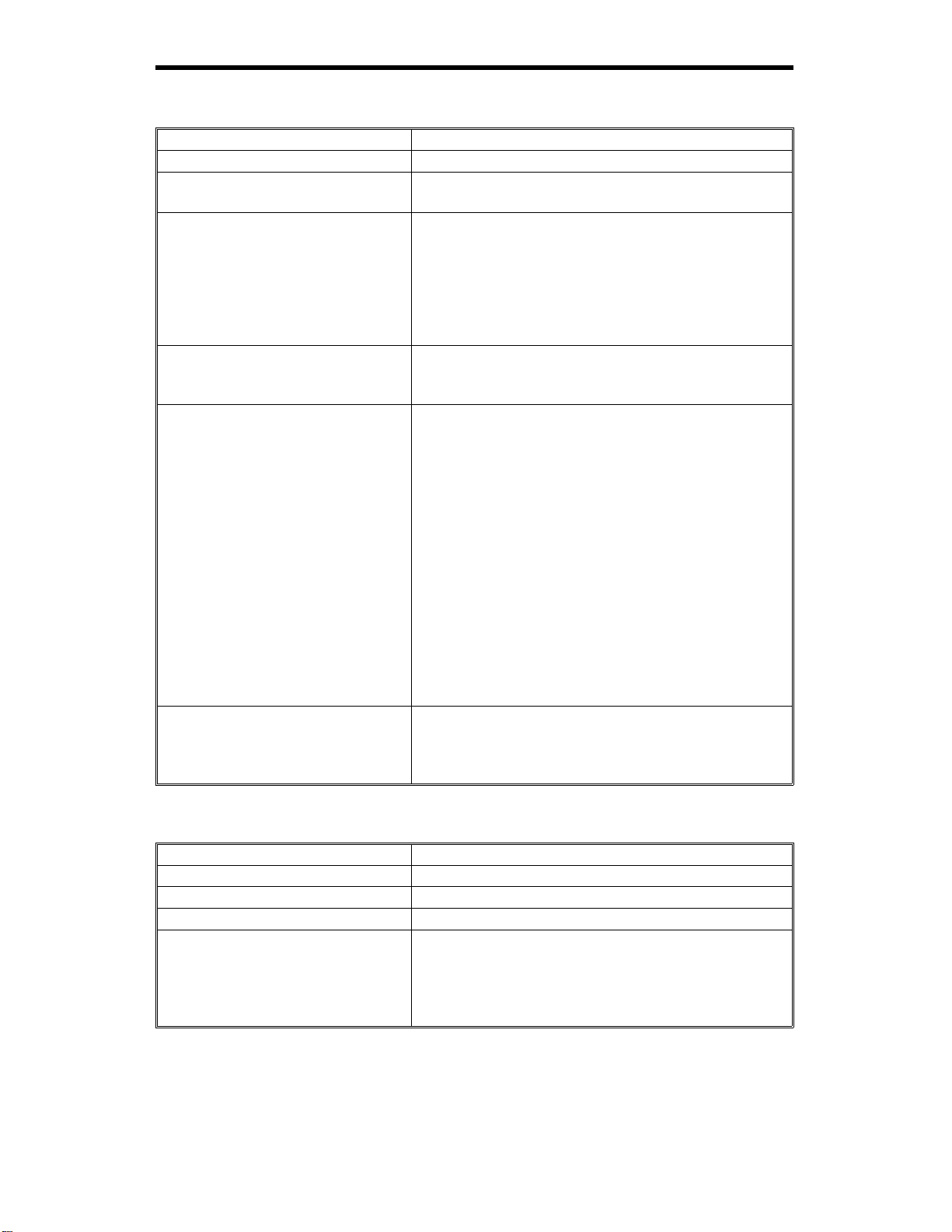
1.3. BLOCK DIAGRAM AND DATA PATH
The printer int erface u nit co nsists o f a contr oller board and an inter face board (PIF-L) .
FDU
FCE
Fax
Page
Memory
PSTN
Printer Interface
Controller PIF-L
Firmware
CPU CPU
NCU
Modem
Page
Memory
ADDRESS/DATA BUS
Cartridge
(Optional)
Font or PostScript
Compatible
Bi-Centronics I/F
PC-AT
(Optional)
LocalTalk I/F
Macintosh
Video/Command Interface
CPU
Laser Unit
H144V501.wmf
The Printer Inte rface Unit consists of two (2) logic boards ca lled the
Controller Board and the Interface Board (identified in the Service Manual as
the PIF-L Board).
The Controller Board contains a CPU chip, ROM for the firmware, Page
Memory, an optional Font or Postscript Interface Connector and two (2) Host
Interface Connectors ( a standard Bi-Centronic or an optional Local Talk).
Refer to the Controller Board Specifications for additional information.
The PIF-L Board also contains a CPU chip which is used to emulate the
commands fro m the Controller Board and to modify the displaye d message
in the display panel of the FAX machine. For example, if the FAX machine
can not use Legal size paper, the CPU chip on the PIF-L board will modify
the displayed message in the FAX machine to eliminate the displayed
selectio n of the Legal size paper. If the opti on of the legal size paper is not
displayed, the operator can not choose the legal size paper.
Data Path
The Controller’s CPU chip will inter pre t the print data from the host computer
and will write an imaginary page of data in the Page Me mory on the
Controller Board. After a page of prin t data has been stored in the Page
Memory, the Controller CPU chip will transfer the page of print data to the
CPU chip in the FA X machi ne will then pass the data direct ly to the Laser
Unit for printing.
SM 1-2 PIF130

The interface bet ween the CPU chips on the Controller board and the FAX
machine is known as "Video Interface". The function of the Video Interface is
to specify the handshaking pro cedure and the timing of the data transfer.
Dual Acce ss
Since the printer resources are shared, the FAX machine was designed to
perform multiple tasks.
If a FA X message is recei ved while the machine is busy printing data fro m
the computer, the F A X messa ge will be received an d the data will be
temporary stor ed in the S AF me mory of the FAX machine. At the co mpletion
of the computer print task, the machine will pr int the received FAX message
that was stored in the SAF Memory.
If the computer attempts to initiate a print task while the FAX machine is busy
receiving a FAX message or printing a report, the print data from the
computer will be received and stored in the Page Memory on the Controller
Board. At the complet ion of the FAX machin e t ask, the ma chine will swit ch
the printer resources of the Controller board to the computer printing task. If
the print data exceeds the Control ler’s me mory size, the print data will be
spooled in the co mputer (if the computer’s oper ati n g system or the
Application Program contains the Print Spooler Function).
The term "Spoole r" i s an acron y m for Simult aneous Print Operation On Line.
Print Spooler is a computer sof tware program that, when the printer is busy,
will intercept the print data tha t is on the way to the printer and will redire ct it
to a disk or memory. When the printer is no longer busy, the print data will
then be sent to the printer. An advantage of the Prin t Spooler feature is that
by diverting the entire print job to disk or memory and then coordinating it
with the printer, frees the user fro m waiti ng unti l the pri n t task is complet ed
before moving to another task.
1.4. POWER DISTRIBUTION
The required +24 volts and the +5 volts are supplied to the Printer Interface
from the FAX machine. The PIF-L board will then generate a different +5
volts for the CPU chips located on the PIF-L and Controller boar ds.
PIF13 0 1-3 SM

2. DETAILED S ECTION DE SCRIPTIONS
2.1. CONTROLLER
2.1.1. Bi-Centronics TM Interface
The parallel interface connector pin assignments and a description of the
interface signa ls are sho wn in the tabl e belo w.
Signal
Pin
10 28
11 29 BUSY OUT
12 30 PE OUT
13 — SLCT OUT
14 —
15 — NC — Not used
16 — GND —
17 —
18 — NC —
19~30 — GND — T wist ed-pai r return signal ground level.
31 — INIT IN
Return
Pin
119
2
3
4
5
6
7
8
9
20
21
22
23
24
25
26
27
CHASSIS
Signal Direction Description
STROBE pulse for readi ng data.
The
STROBE IN
DA TA1
DA TA2
DA TA3
DA TA4
DA TA5
DA TA6
DA TA7
DA TA8
ACKNLG OUT
AUTO IN
GND
IN
IN
IN
IN
IN
IN
IN
IN
—
The pulse width of the signal mu st be at
least 0 .5 µs at the receiving term inal .
The signals represent the parallel data
bits 1 to 8. Each signal is at the HIGH
level when the data is a logi c al 1 a nd
LOW when it is a logi cal 0.
About a 10 µs pulse width. A LOW
signal indicates that data ha s been
received and the printer is ready to
accept more data.
A HIGH signal indi cates that the pri nter
cannot receive data. The signal will go
HIGH in the following cases:
1. During printin g
2. When off line
3. During a printer-error stat e
A HIGH signal indi cates that the pri nter is
out of paper.
Availabl e onl y for bidirect i onal use.
Available only for bidirectional use.
A LOW signal enables an automatic line
feed upon receiving a CR signal. This
signal is only detected when the machine
has just been turned on, or when the
printer interface is initialized.
In ESC/P
operation in accordance with the
SelecT yp e
In HP
Logic ground level
Chassis ground, which is connected to
the signal ground.
Not used
When this signal goes LOW , the print er
controller will ignore the
®
mode, this signal effects a CR
TM
TM
setting.
mode, this signal will be ignored.
STROBE signal.
PIF13 0 2-1 SM

Signal
Pin
32 —
33 — GND —
34 — NC —
35 — +5V —
36 —
Return
Pin
Signal Direction Description
This signal will go LOW when the printer
is:
ERROR OUT
SLCTIN IN
1. Out of paper
2. In an error state
3. Off line
Same as for Pins 19~30
Not used
Pulled up to +5V through a 1KΩ resistor.
Availabl e onl y for bidirect i onal use.
Note: • All interface condi t ions are based on TTL levels. Both the rise and
fall times of each signal must be less than 0.2 microseconds.
• Data transfer is carried out by observing the ACKNLG or BUSY
signal.
(Data transfer to the printer interface can only be carried out after
the receipt of the ACKNLG signal or when the level of the B U SY
signal i s LOW.)
• The "Direction" column refers to the direction of signal flow as
viewed from the pri nt er interface.
• Return denotes the twisted-pair return to be connected at signal
ground level .
For the interface wiring, use a twisted-pair cable for each signal
and to complete the connection on the return side.
• The pulse width of the ACKNLG signal will vary.
SM 2-2 PIF130
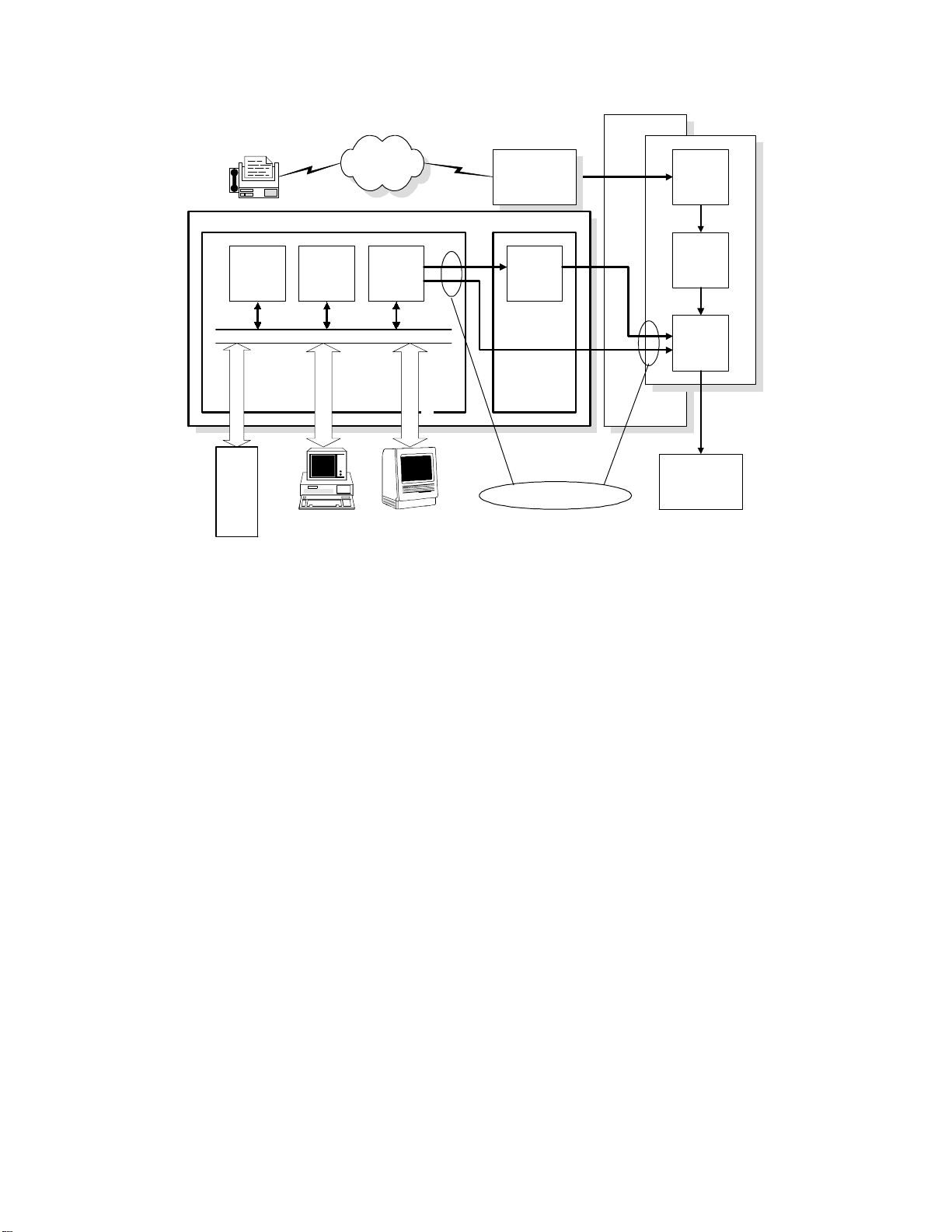
To enable bidirectional parallel interface communications between the printer
and computer, set the connector pin assignments as follows:
Printer Interface Computer
1
2
3
4
5
6
7
8
9
10
11
12
13
14
17
•
31
32
36
Chassis GND
• 16, 19—30, 33 connected to GND
1
2
3
4
5
6
7
8
9
10
11
12
13
14
15
16
17
18—25
H144d501.wmf
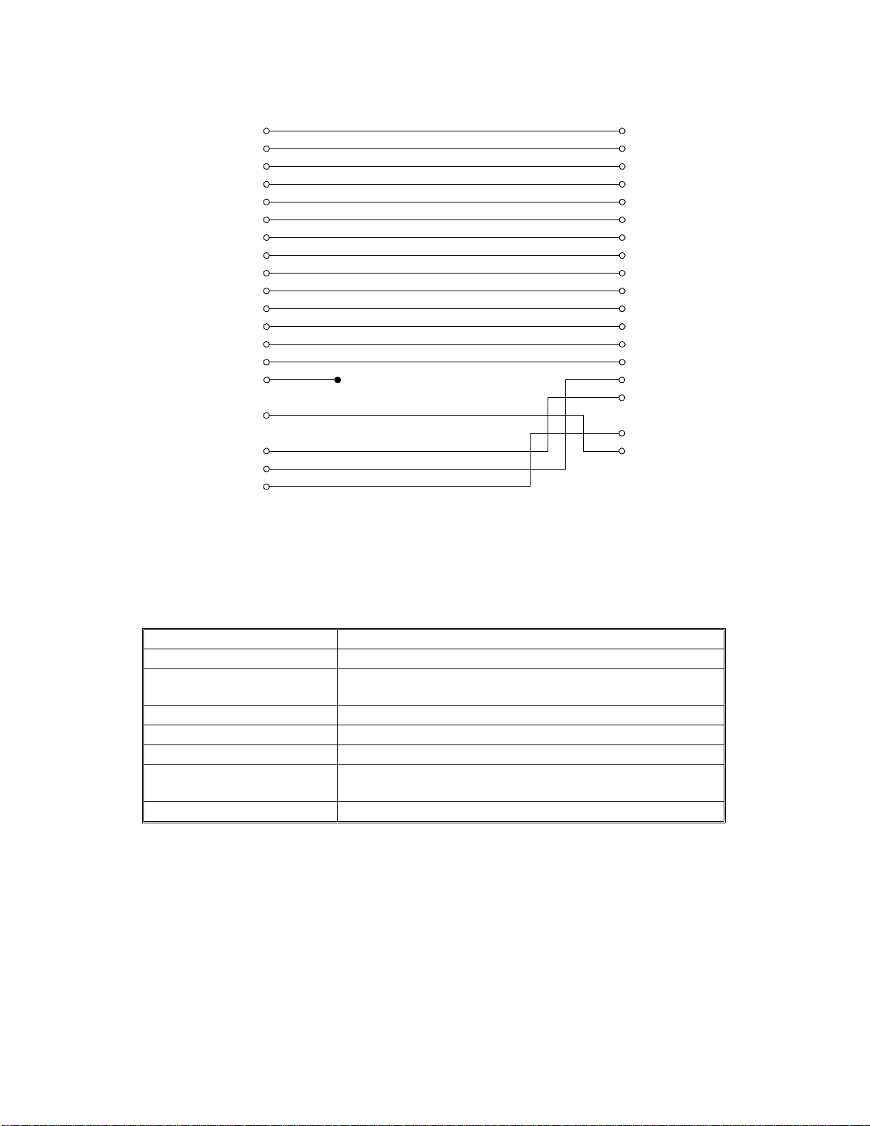
2.1.2. LocalTalk TM Interface (Optional)
Specifications
Compatibility Phase 1 and phase 2
Baud rate 230.4 kbps
Topology Par al lel bus, lo w-re sistance transf orm er i solated, floati n g
ground.
Signaling standard EIA standard RS422, balanced vol tage
Signal encoding FMO (bi-phase) space
Frame format SDLC (Synchronous Data Link Control)
Node identification AppleTalk
action required.
Cabling AppleTalk
TM
logical address is self-configuring; no u ser
TM
8-pin mini DI N
PIF130 2-3 SM
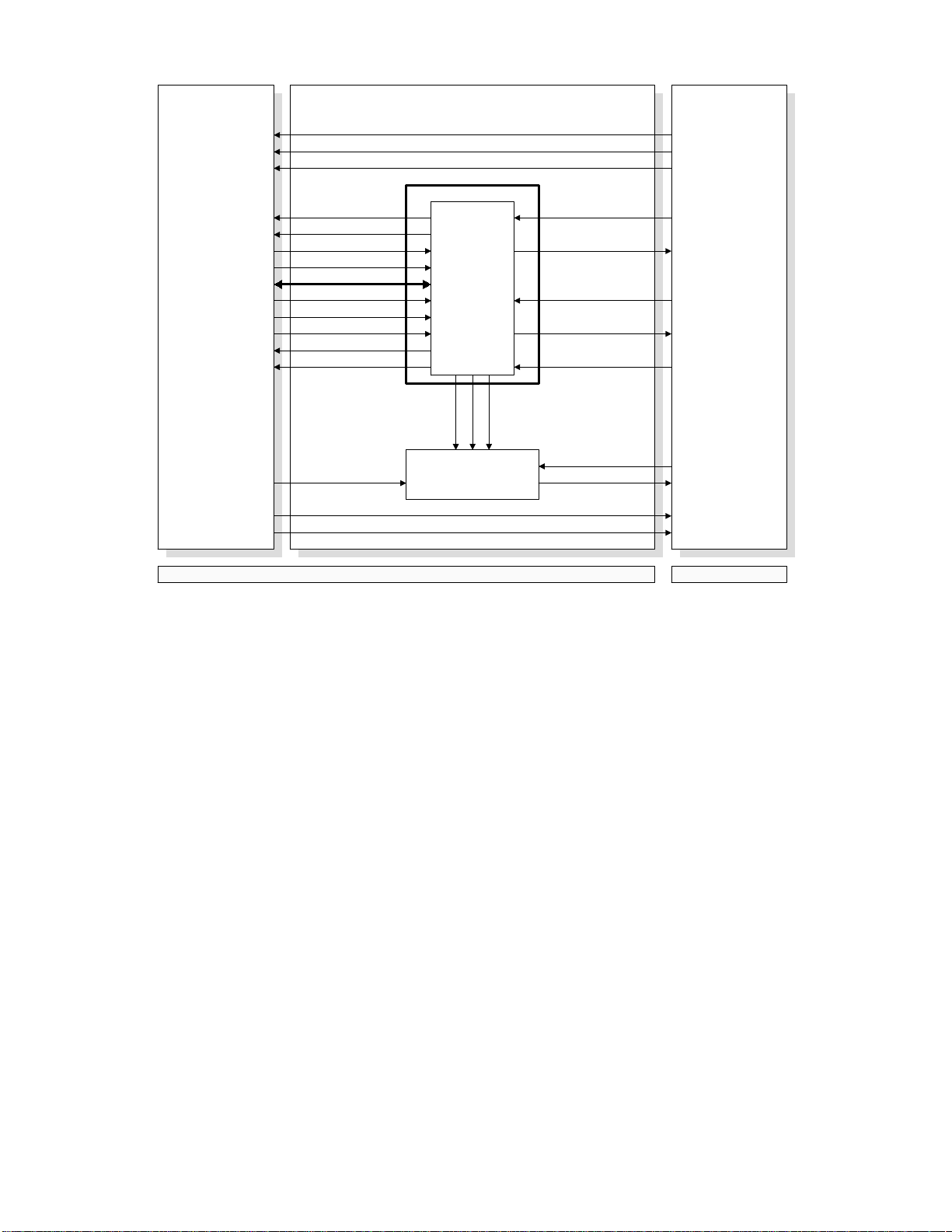
2.2. PIF
Controller PIF-L
5LSYNC
5VSYNC
5PRRDY
IC4
SWINT
PPRDY
RESET
CONNECT
LCD/KEY DATA
SERIAL CLOCK
CTBSY
COMMAND SERIAL DATA
STSBSY
STATUS
Print Density Adjustment
CPU
NORMAL
DARK
Circuit
5PRINT
5CPRDY
FDU/FCE
on the
Fax Machine
5PIFRESET
1INTPR
SERIAL CLOCK
SERIAL DATA
LIGHT
5LGATE
VIDEO SIGNALVIDEO SIGNAL
Printer Interface Unit
FAX
H144D502.wmf
The CPU on the PIF-L board acts as a interpreter (e mulator) between the
printer controller board and the FAX machine.
2.2.1. Command and Status Signals
The controller board will send various command signals to the FAX machine
through the CPU on the PIF-L board requesting hardware status (e.g.,
cassette paper size, jam, toner end) and for specifying a cassette for
printing. The FAX machine will respond to each command signal with a
status signal.
The CPU on the PIF-L board emulates the commands for FAX machine’s
hardware specifications (e.g, some models can have only one cassette).
SM 2-4 PIF130

2.2.2. Key/Display Emulation
When the operato r is using the prin ter function of the FA X machi ne, the FAX
machine’s keys and LCD panel are connected to the printer controller board.
through the CPU on the PIF-L board.
Because the capabilities of the contro ller and the FAX machine are not the
same (for exa mple, Mon arch paper is avail a ble with the controller, but not
with the FAX machine), the PIF-L board will emulate the user key operations
for the controller board and the display message to the FAX machine, so that
the user cannot select settings that the FAX machine is not capable of
performing.
2.2.3. Print Density Control
The controller controls the print density adjustment using the Level 2 menu.
Depending on the densi ty sett ing sent from the controller boa rd, th e PIF-L
board will adjust the pulse width of each pixel.
2.2.4. Printer Interface Reset
FDUPIF-LController
CPU
+5V
CN5-1,2
+5V +5V
+5V
CPU
RESET
DC/DC
Converter
5PIFRESET
Reset Circuit
+24V
+5V
CN1-20
CN1-2
FCE
CPU
H144D504.wmf
If the F AX mach ine’ s CPU chip activates the 5PIFRESET signal, the rese t
circuit on the PIF-L board will reset its CPU, and the DC/DC converter on the
will shut down the +5V supply to the Controller board.
The procedure for totally resetting the printer interface is described in
Section 4.
PIF130 2-5 SM
 Loading...