

Page 1

COLOR CONTROLLER E-700
INSTALLATION AND SERVICE
GUIDE
for Ricoh Aficio Color 6010, 6110
Savin SDC410, SDC410E
Gestetner CS210, CS210e
RexRotary CS810, CS810E
nashuatec CS510, CS510e
infotec 7410, 7410E
Lanier 5710 AG, 5710E AG
A guide for service technicians
Part Number: 45016553
Page 2

Page 3

Copyright © 2000 Electronics For Imaging. All rights reserved.
This publication is protected by copyright, and all rights are reserved. No part of it may be reproduced or transmitted in any form or by any means for any purpose without express prior
written consent from Electronics For Imaging, except as expressly permitted herein. Information in this document is subject to change without notice and does not represent a commitment
on the part of Electronics For Imaging.
The software described in this publication is furnished under license and may only be used or copied in accordance with the terms of such license.
Patents: 5,867,179; 5,835,788; 5,666,436; 5,553,200; 5,543,940; 5,537,516; 5,517,334; 5,506,946;5,424,754; 5,343,311; 5,212,546; 4,941,038; 4,837,722; 4,500,919, D406,117
Trademarks
EFI, the EFI logo, Fiery, the Fiery logo, and Rip-While-Print are trademarks registered in the U.S. Patent and Trademark Office. Fiery ZX, Fiery LX, Fiery Driven, the Fiery Driven logo,
Command WorkStation, AutoCal, Starr Compression, Memory Multiplier, ColorWise, NetWise, and VisualCal are trademarks of Electronics For Imaging.
infotec and the infotec logo are trademarks of the infotec Europe B.V., which may be registered in certain jurisdictions.Adobe, the Adobe logo, Adobe Illustrator, PostScript, Adobe
Photoshop, Adobe Separator, and Adobe PageMaker are registered trademarks of Adobe Systems Incorporated, registered in certain jurisdictions. EPS (Encapsulated PostScript) is a trademark
of Altsys Corporation. Apple, the Apple logo, AppleShare, AppleTalk, EtherTalk, LaserWriter, and Macintosh are registered trademarks, and MultiFinder is a trademark of Apple Computer,
Inc. Microsoft, MS, MS-DOS, and Windows are registered trademarks of Microsoft in the US and other countries. QuarkXPress is a registered trademark of Quark, Inc. Times, Helvetica,
and Palatino are trademarks of Linotype AG and/or its subsidiaries. ITC Avant Garde, ITC Bookman, ITC Zapf Chancery, and ITC Zapf Dingbats are registered trademarks of International
Typeface Corporation. Ethernet is a registered trademark of Xerox Corporation. Farallon, PhoneNET PC, and PhoneNET Talk are trademarks of Farallon Computing, Inc. COPS and
COPSTalk are trademarks of CoOperative Printing Solutions, Inc. NetWare and Novell are registered trademarks and Internetwork Packet Exchange (IPX) is a trademark of Novell, Inc.
SyQuest is a registered trademark, in the United States and certain other countries, of SyQuest Technology, Inc. UNIX is a registered trademark of UNIX System Laboratories, a wholly
owned subsidiary of Novell, Inc. PANTONE is a registered trademark of Pantone, Inc.
All other terms and product names may be trademarks or registered trademarks of their respective owners, and are hereby acknowledged.
Legal Notices
APPLE COMPUTER, INC. (“APPLE”) MAKES NO WARRANTIES, EXPRESS OR IMPLIED, INCLUDING WITHOUT LIMITATION THE IMPLIED WARRANTIES OF
MERCHANTABILITY AND FITNESS FOR A PARTICULAR PURPOSE, REGARDING THE APPLE SOFTWARE. APPLE DOES NOT WARRANT, GUARANTEE, OR MAKE
ANY REPRESENTATIONS REGARDING THE USE OR THE RESULTS OF THE USE OF THE APPLE SOFTWARE IN TERMS OF ITS CORRECTNESS, ACCURACY,
RELIABILITY, CURRENTNESS, OR OTHERWISE. THE ENTIRE RISK AS TO THE RESULTS AND PERFORMANCE OF THE APPLE SOFTWARE IS ASSUMED BY YOU.
THE EXCLUSION OF IMPLIED WARRANTIES IS NOT PERMITTED BY SOME STATES. THE ABOVE EXCLUSION MAY NOT APPLY TO YOU.
IN NO EVENT WILL APPLE, ITS DIRECTORS, OFFICERS, EMPLOYEES OR AGENTS BE LIABLE TO YOU FOR ANY CONSEQUENTIAL, INCIDENTAL OR INDIRECT
DAMAGES (INCLUDING DAMAGES FOR LOSS OF BUSINESS PROFITS, BUSINESS INTERRUPTION, LOSS OF BUSINESS INFORMATION, AND THE LIKE)
ARISING OUT OF THE USE OR INABILITY TO USE THE APPLE SOFTWARE EVEN IF APPLE HAS BEEN ADVISED OF THE POSSIBILITY OF SUCH DAMAGES.
BECAUSE SOME STATES DO NOT ALLOW THE EXCLUSION OR LIMITATION OF LIABILITY FOR CONSEQUENTIAL OR INCIDENTAL DAMAGES, THE ABOVE
LIMITATIONS MAY NOT APPLY TO YOU.
[including negligence], product liability or otherwise), will be limited to $50.
Restricted Rights Legends
For defense agencies: Restricted Rights Legend. Use, reproduction, or disclosure is subject to restrictions set forth in subparagraph (c)(1)(ii) of the Rights in Technical Data and Computer
Software clause at 252.227.7013.
For civilian agencies: Restricted Rights Legend. Use, reproduction, or disclosure is subject to restrictions set forth in subparagraph (a) through (d) of the commercial Computer Software
Restricted Rights clause at 52.227-19 and the limitations set forth in Electronics For Imaging’s standard commercial agreement for this software. Unpublished rights reserved under the
copyright laws of the United States.
Printed in the United States of America on recycled paper.
Apple’s liability to you for actual damages from any cause whatsoever, and regardless of the form of the action (whether in contract, tort
Page 4

FCC Information
WARNING: FCC Regulations state that any unauthorized changes or modifications to this equipment not expressly approved by the manufacturer could void the user’s authority to operate
this equipment.
Class B Declaration of Conformity
This equipment has been tested and found to comply with the limits for a class B digital device, pursuant to Part 15 of the FCC rules. These limits are designed to provide reasonable
protection against harmful interference in a residential installation. This equipment generates, uses and can radiate radio frequency energy and if not installed and used in accordance with
the instructions, may cause harmful interference to radio communications. However, there is no guarantee that interference will not occur in a particular installation.
If this equipment does cause harmful interference to radio or television reception, which can be determined by turning the equipment off and on, the user is encouraged to try to correct the
interference by one or more of the following measures:
Reorient or relocate the receiving antenna.
Increase the separation between the equipment and receiver.
Connect the equipment into an outlet on a circuit different from that to which the receiver is connected.
Consult the dealer or an experienced radio/TV technician for help.
In order to maintain compliance with FCC regulations, shielded cables must be used with this equipment. Operation with non-approved equipment or unshielded cables is likely to result
in interference to radio and TV reception. The user is cautioned that changes and modifications made to the equipment without the approval of manufacturer could void the user’s authority
to operate this equipment.
Industry Canada Class B Notice
This Class B digital apparatus meets all the requirements of the Canadian Interference-Causing Equipment Regulations.
Avis de Conformation Classe B de l’Industrie Canada
Cet appareil numérique de la classe B respecte toutes les exigences du Règlement sur le matériel brouilleur du Canada.
RFI Compliance Notice
This equipment has been tested concerning compliance with the relevant RFI protection requirements both individually and on system level (to simulate normal operation conditions).
However, it is possible that these RFI Requirements are not met under certain unfavorable conditions in other installations. It is the user who is responsible for compliance of his particular
installation.
Dieses Geraet wurde einzeln sowohl als auch in einer Anlage, die einen normalen Anwendungsfall nachbildet, auf die Einhaltung der Funk-entstoerbestimmungen geprueft. Es ist jedoch
moeglich, dass die Funk-enstoerbestimmungen unter unguenstigen Umstaenden bei anderen Geraetekombinationen nicht eingehalten werden. Fuer die Einhaltung der Funkentstoerbestimmungen seigner gesamten Anlage, in der dieses Geraet betrieben wird, ist der Betreiber verantwortlich.
Compliance with applicable regulations depends on the use of shielded cables. It is the user who is responsible for procuring the appropriate cables.
Einhaltung mit betreffenden Bestimmungen kommt darauf an, dass geschirmte Ausfuhrungen gebraucht werden. Fuer die beschaffung richtiger Ausfuhrungen ist der Betreiber
verantwortlich.
Page 5

Software License Agreement
Before using the Software, please carefully read the following terms and conditions. BY USING THIS SOFTWARE, YOU SIGNIFY THAT YOU HAVE ACCEPTED THE TERMS OF
THIS AGREEMENT. If you cannot or do not accept these terms, you may return the entire package within ten (10) days to the Distributor or Dealer from which you obtained them for
a full refund.
Electronics For Imaging grants to you a non-exclusive, non-transferable license to use the software and accompanying documentation (“Software”) included with the E-700 you have
purchased, including without limitation the PostScript® software provided by Adobe Systems Incorporated.
You may:
a. use the Software solely for your own customary business purposes and solely with E-700;
c. use the trademarks used by Electronics For Imaging to identify the Coded Font Programs and Typefaces reproduced therefrom (“Trademarks”); and
d. assign your rights under this Agreement to a transferee of all of your right, title and interest in and to E-700 provided the transferee agrees to be bound by all of the terms and conditions
of this Agreement.
You may not:
a. make use of the Software, directly or indirectly, to print bitmap images with print resolutions of 600 dots per inch or greater, or to generate fonts or typefaces for use other than with E-700;
b. make or have made, or permit to be made, any copies of the Software, Coded Font Programs, accompanying documentation or portions thereof, except as necessary for use with the E-700
unit purchased by you; provided, however, that under no circumstances may you make or have made, or permit to be made, any copies of that certain portion of the Software which has
been included on the E-700 hard disk drive. You may not copy the documentation;
c. attempt to alter, disassemble, decrypt or reverse engineer the Software, Coded Font Programs or accompanying documentation.
d. rent or lease the Software.
Proprietary Rights
You acknowledge that the Software, Coded Font Programs, Typefaces, Trademarks and accompanying documentation are proprietary to Electronics For Imaging and its suppliers and that
title and other intellectual property rights therein remain with Electronics For Imaging and its suppliers. Except as stated above, this Agreement does not grant you any right to patents,
copyrights, trade secrets, trademarks (whether registered or unregistered), or any other rights, franchises or licenses in respect of the Software, Coded Font Programs, Typefaces, Trademarks
or accompanying documentation. You may not adapt or use any trademark or trade name which is likely to be similar to or confusing with that of Electronics For Imaging or any of its
suppliers or take any other action which impairs or reduces the trademark rights of Electronics For Imaging or its suppliers. The trademarks may only be used to identify printed output
produced by the Coded Font Programs. At the reasonable request of Electronics For Imaging, you must supply samples of any Typeface identified with a trademark.
The MacApp software is proprietary to Apple Computer, Inc. and is licensed to Electronics For Imaging for distribution only for use in combination with Fiery software utilities.
Confidentiality
You agree to hold the Software and Coded Font Programs in confidence, disclosing the Software and Coded Font Programs only to authorized users having a need to use the Software and
Coded Font Programs as permitted by this Agreement and to take all reasonable precautions to prevent disclosure to other parties.
Remedies
Unauthorized use, copying or disclosure of the Software, Coded Font Programs, Typefaces, Trademarks or accompanying documentation will result in automatic termination of this license
and will make available to Electronics For Imaging other legal remedies.
Limited Warranty And Disclaimer
Electronics For Imaging warrants that, for a period of ninety (90) days from the date of delivery to you, the Software under normal use will perform without significant errors that make it
unusable. Electronics For Imaging’s entire liability and your exclusive remedy under this warranty (which is subject to you returning E-700 to Electronics For Imaging or an authorized dealer)
will be, at Electronics For Imaging’s option, to use reasonable commercial efforts to attempt to correct or work around errors, to replace the Software with functionally equivalent software,
or to refund the purchase price and terminate this Agreement. Some states do not allow limitations on duration of implied warranty, so the above limitation may not apply to you.
Except for the above express limited warranty, Electronics For Imaging makes and you receive no warranties or conditions on the Products, express, implied, or statutory, and Electronics For
Imaging specifically disclaims any implied warranty or condition of merchantability or fitness for a particular purpose.
For warranty service, please contact your authorized service/support center.
EXCEPT FOR THE ABOVE EXPRESS LIMITED WARRANTY, ELECTRONICS FOR IMAGING MAKES AND YOU RECEIVE NO WARRANTIES OR CONDITIONS ON
THE SOFTWARE OR CODED FONT PROGRAMS, EXPRESS, IMPLIED, STATUTORY, OR IN ANY OTHER PROVISION OF THIS AGREEMENT OR COMMUNICATION
WITH YOU, AND ELECTRONICS FOR IMAGING SPECIFICALLY DISCLAIMS ANY IMPLIED WARRANTY OR CONDITION OF MERCHANTABILITY OR FITNESS
FOR A PARTICULAR PURPOSE. Electronics For Imaging does not warrant that the operation of the software will be uninterrupted or error free or that the Software will meet your specific
requirements.
Limitation Of Liability
IN NO EVENT WILL ELECTRONICS FOR IMAGING OR ITS SUPPLIERS BE LIABLE FOR ANY DAMAGES, INCLUDING LOSS OF DATA, LOST PROFITS, COST OF
COVER OR OTHER SPECIAL, INCIDENTAL, CONSEQUENTIAL OR INDIRECT DAMAGES ARISING FROM THE USE OF THE SOFTWARE, CODED FONT
PROGRAMS OR ACCOMPANYING DOCUMENTATION, HOWEVER CAUSED AND ON ANY THEORY OF LIABILITY. THIS LIMITATION WILL APPLY EVEN IF
ELECTRONICS FOR IMAGING OR ANY AUTHORIZED DEALER HAS BEEN ADVISED OF THE POSSIBILITY OF SUCH DAMAGE. YOU ACKNOWLEDGE THAT THE
PRICE OF THE UNIT REFLECTS THIS ALLOCATION OF RISK. BECAUSE SOME STATES/JURISDICTIONS DO NOT ALLOW THE EXCLUSION OR LIMITATION OF
LIABILITY FOR CONSEQUENTIAL OR INCIDENTAL DAMAGES, THE ABOVE LIMITATION MAY NOT APPLY TO YOU.
Export Controls
You agree that you will not export or re-export the Software or Coded Font Programs in any form without the appropriate United States and foreign government licenses. Your failure to
comply with this provision is a material breach of this Agreement.
Page 6

Government Use
Use, duplication or disclosure of the Software by the United States Government is subject to restrictions as set forth in subdivision (c) (1) (ii) of the Rights in Technical Data and Computer
Software clause at DFARS 252.227-7013 or in subparagraphs (c) (1) and (2) of the Commercial Computer Software—Restricted Right Clause at 48 CFR 52.227-19, as applicable.
Third Party Beneficiary
You are hereby notified that Adobe Systems Incorporated, a California corporation located at 345 Park Avenue, San Jose, CA 95110-2704 USA (“Adobe”) is a third-party beneficiary to this
Agreement to the extent that this Agreement contains provisions which relate to your use of the Fonts, the Coded Font Programs, the Typefaces and the Trademarks licensed hereby. Such
provisions are made expressly for the benefit of Adobe and are enforceable by Adobe in addition to Electronics For Imaging.
General
This Agreement will be governed by the laws of the State of California.
This Agreement is the entire agreement held between us and supersedes any other communications or advertising with respect to the Software, Coded Font Programs and accompanying
documentation.
If any provision of this Agreement is held invalid, the remainder of this Agreement shall continue in full force and effect.
If you have any questions concerning this Agreement, please write to Electronics For Imaging, Attn: Licensing Dept. or see Electronics For Imaging’s web site at www.efi.com.
Electronics For Imaging
303 Velocity Way
Foster City, CA 94404
Page 7

xi
xi
Contents
Preface
About this guide
About the illustrations in this guide
Terminology and conventions
Precautions
Tools you will need
Chapter 1: Introduction
xii
xiii
xiv
Features
How the E-700 operates
E-700 print options
User software
Fiery WebTools 1-4
Chapter 2: Installation
Setting customer expectations
Unpacking the E-700
Preparing for installation
Opening the copier
Installing the E-700 in the copier
Reassembling the copier
Initial startup
Printing a Test Page
Printing the Configuration page
Connecting the E-700 to the network
Ethernet network connection 2-10
Chapter 3: Using the E-700 Operation Panel
1-1
1-2
1-3
1-3
2-1
2-2
2-3
2-3
2-5
2-6
2-7
2-8
2-9
2-10
Overview
Keys
Activity indicators
Screens
Functions screen 3-4
Startup screen 3-5
3-1
3-2
3-2
3-3
vii
Page 8

Contents
Chapter 4: Service Procedures
Overview
Accessing the E-700
Checking E-700 internal connections
Replacing parts of the E-700
E-700 board 4-8
Video interface board 4-12
SCSI interface board 4-14
DIMMs 4-15
Battery 4-16
CPU fan 4-17
Exhaust fan 4-18
Hard disk drive 4-19
Restoring E-700 functionality after service
E-700 system software
System software installation reminders 4-24
Installing system software using the SCSI interface connector 4-25
Chapter 5: Troubleshooting Procedures
The troubleshooting process
Where problems occur
Before you go to the customer site
Preliminary on-site checkout
Checking connections 5-4
General E-700 system errors
Video board diagnostics
Printing the Test Page
Checking network connections
Printing to the E-700 5-10
General printing problems 5-11
4-1
4-3
4-5
4-7
4-22
4-24
5-1
5-2
5-3
5-4
5-5
5-7
5-8
5-9
viii
Page 9

Contents
Appendix A: Specifications
Hardware features
Networking and connectivity
User software
Safety and emissions compliance
Output voltage
Appendix B: Controller Interface Type F
Installation Procedure
Index
A-1
A-1
A-1
A-1
A-2
B-1
ix
Page 10

Page 11

Preface
About this guide
The Installation and Service Guide is intended for certified Color Controller E-700 and
copier service technicians. If you have not received certification, you should not attempt
to install or service the E-700. Electronics For Imaging does not warrant the performance
of the E-700 if installed or serviced by non-certified personnel.
About this guide
This guide is divided into the following sections:
• “Preface”
Gives general information about this guide and general information that you should
know before you attempt to install or service the E-700.
• Chapter 1, “Introduction.”
Provides general information about the E-700.
• Chapter 2, “Installation.”
Provides detailed instructions for installing the E-700 into the copier.
• Chapter 3, “Using the E-700 Operation Panel.”
Describes the E-700 Operation Panel and how to use it.
• Chapter 4, “Service Procedures.”
Describes removal and replacement procedures for E-700 components.
• Chapter 5, “Troubleshooting Procedures.”
Identifies the source of common problems and suggests ways of correcting them.
• Appendix A, “Specifications.”
Summarizes the hardware and networking features of the E-700 controller.
• Appendix B, “Controller Interface Type F.”
Reprints the Installation Procedure for the Controller Interface Type F kit, which must
be installed before installing the E-700.
Customers should not use the technical service documentation. Do not leave this guide
behind after you make a service call.
About the illustrations in this guide
Illustrations in this guide reflect the E-700 at the time of publication. Components
shown in these illustrations are subject to change. To receive information about any
components that do not match illustrations in this guide, contact your authorized
service/support center.
xi
Page 12

Preface
Terminology and conventions
The term copier refers to the following copiers in which the Controller Interface Type F
kit and the E-700 Controller kit are installed:
Copier Basic Auto-Duplex Model
(A257)
Ricoh
Savin
Gestetner
RexRotary
nashuatec
infotec
Lanier
Aficio Color 6010 Aficio Color 6110
SDC410 SDC410E
CS210 CS210e
CS810 CS810E
CS510 CS510e
7410 7410E
5710 AG 5710E AG
Edit Auto-Duplex Model
(A269)
The term “network administrator” refers to the person responsible for maintaining the
network at the customer site.
The term “Fiery Operation Panel” describes the area within the copier Operation Panel
that is dedicated to the E-700 printer controller. It includes the display window and the
surrounding keys and activity lights.
The term “PC” refers to any IBM PC or compatible computer running Windows over
MS-DOS.
The term “E-700 board” refers to the E-700 printer controller (the main board in the
E-700).
xii
NOTE:
The term “100BaseT” is used throughout this manual to refer to 100BaseTX.
The term “HDD” refers to the hard disk drive that is part of the E-700 assembly.
The term “I/F unit” refers to the portion of the controller interface kit that houses the
E-700. See the Controller Interface Type F Installation Procedure for more information.
This document is included in Appendix B, “Controller Interface Type F.”
The note indicator highlights important messages and additional information.
The caution icon indicates a need for special care and safety when handling the
equipment.
Page 13

Precautions
Precautions
Always observe the following general precautions when installing and servicing the
E-700:
1. Report any shipping damage.
If there is any evidence of shipping or handling damage to packing boxes or their
contents, save the damaged boxes and parts, call the shipper immediately to file a claim,
and notify your authorized service/support center.
2. Never alter an existing network without permission.
The E-700 probably connects to an existing Local Area Network (LAN) based on
Ethernet hardware. The network is the link between the customer’s computer, existing
laser printers, and other prepress equipment. Never disturb the LAN by breaking or
making a network connection, altering termination, installing or removing networking
hardware or software, or shutting down networked devices without the knowledge and
express permission of the network administrator.
3. Never enter an IP address in Network Setup.
Only the network administrator should enter an IP address on a network device.
Assigning an incorrect IP address to the E-700 can cause unpredictable errors on any or
all devices.
4. Follow standard ESD (electrostatic discharge) precautions while working on the internal
components of the copier.
Static is always a concern when servicing electronic devices. It is highly unlikely that the
area around the copier is static-free. Carpeting, leather-soled shoes, synthetic clothing
fibers, silks, and plastics may generate a static charge of more than 10,000 volts. Static
discharge is capable of destroying the circuits etched in silicon microchips, or
dramatically shortening their life span. By observing standard precautions, you may avoid
extra service calls and save the cost of a new board.
When possible, work on a ground-connected antistatic mat. Wear an antistatic
wristband, grounded at the same place as the antistatic mat. If that is not possible:
• Attach a grounding strap to your wrist. Attach the other end to a good ground.
• When you remove an electronic component, place it into an antistatic bag
immediately. Do not walk across a carpet or vinyl floor while carrying an unprotected
board.
• Leave new electronic components inside their antistatic bags until you are ready to
install them.
• When you unpack the electronic components, touch a metal area of the copier to
discharge the static on your body. Place the components on a grounded antistatic
surface, component-side up.
xiii
Page 14

Preface
5. Avoid flexing printed circuit boards and handle them by opposing edges (not corners)
only.
6. Never set a cup of coffee—or any liquid—on or near any components or the copier.
Tools you will need
To service the E-700, you should bring the following:
• ESD wrist grounding strap
• Antistatic mat
• #0, #1, and #2 Phillips head screwdrivers (non-magnetic)
• 3/16" hex nut driver (recommended)
• Small flat-blade screwdriver (non-magnetic)
• Small needlenose pliers
• Flashlight
• This guide and any technical notes you may have for the E-700.
xiv
Page 15
Chapter 1:
Introduction
Features
1
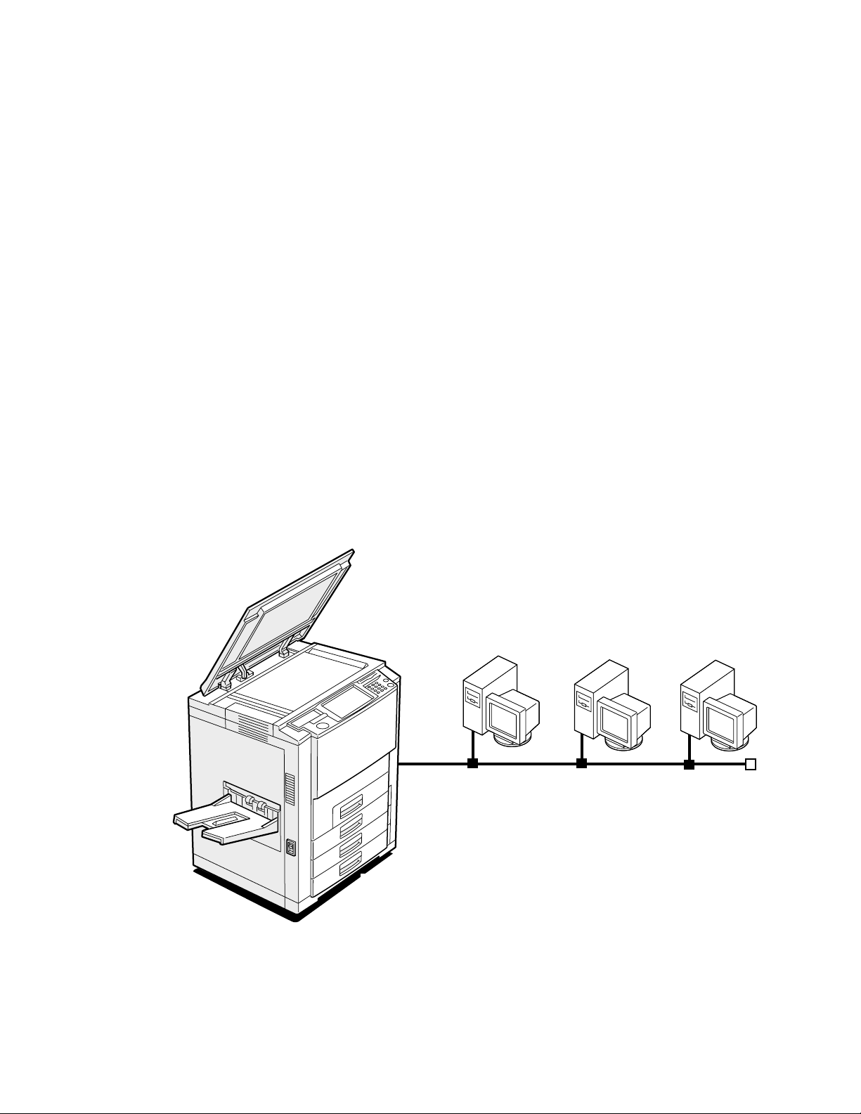
The E-700 is a high performance embedded color controller that provides computer
connectivity and highly efficient color printing capability to digital color copiers. It is
optimized for high-speed communications, processing, rasterization, and printing of
continuous tone color and monochrome (black and white) pages. Users can print from
networked Mac OS computers, from networked PCs running Windows NT, Windows
95/98, Windows 2000, and from UNIX workstations.
Features
As an integral part of the printing system, the E-700 enables users to:
• Send images over AppleTalk, TCP/IP, and Novell networks.
• Spool print jobs and select a printing priority for each job. Users can control spooled
print jobs sent to the E-700 with user software running on networked Mac OS
computers and PCs.
• Print files in color, grayscale, and black and white.
• Use PostScript fonts. The customer can download additional fonts, as needed.
• Use built-in ColorWise
™
color management and NetWise
™
networking features.
Networked computers
Copier
F
IGURE
1-1
E-700 printing system
1-1
Page 16

Introduction
1
How the E-700 operates
The E-700 provides efficient image processing and printing control. The E-700 board
includes a 366MHz Intel Celeron CPU that runs the PostScript Interpreter. It interprets
a page description file to produce the image pattern in memory. The RipChips
board control data management and other system functions, freeing up the CPU for
efficient image data processing.
Two high-speed DIMMs (dual in-line memory modules) on the E-700 board hold image
data during printing. The standard memory configuration is 256MB.
With Fiery Scan software, the E-700 acquires RGB (red, green, blue) image data from the
copier, stores it in memory, and transmits it to the computer that requested the scan.
™
on the
The PCI-based video interface board provides communication with the color engine.
Image data is sent via the video interface connector on the video interface board that
attaches to both the E-700 board and the copier I/F unit. Raster data is supplied to the
laser in the copier at full copier rated speeds.
External devices CopierE-700
E-700 Board
Networked
computers
SCSI Device
SCSI
interface
board
HDD
Network
interface
PCI-ISA
Battery
RTC/
Memory &
Interpreter
RIPChip
BIOS
Super I/O
controller
Operation
Panel
interface
CPU
+5VDC, +12VDC
Print/Scan
Video interface
board
Copier
Operation
Panel
Display
Power supply
1-2
IGURE
F
E-700 functional diagram
1-2
PCI Bus
Page 17

E-700 print options
1
E-700 print options
The E-700’s efficient PostScript capabilities allow customers to use a variety of
applications to create printed color or black and white pages of text and/or images.
The E-700 operates over a network. Since the E-700 has the ability to print an image
while processing the next image (RIP-While-Print
at full copier speeds.
Users can print documents directly from the applications in which they were created. In
addition, the E-700 offers an efficient way to print files that have been saved in
PostScript, EPS (Encapsulated PostScript), or PDF format. These files can be
downloaded directly to the E-700 using the Fiery Downloader, a remote utility provided
with E-700.
™
), it is capable of printing documents
User software
User software is provided on the User Software CD. The network administrator or the
user at the customer site is responsible for installing software onto computers that will use
the E-700 over the network. See Getting Started for details.
The User Software CD includes:
Adobe PS Printer Driver Enables users to print to the E-700 from Windows 95/98,
Windows NT 4.0, and Mac OS computers; also supports
special E-700 and PostScript 3 features.
OTE
Windows 2000 users should use the Microsoft
N
:
PostScript Printer Driver provided with Windows 2000.
PostScript Printer
Description file (PPD)
PostScript Fonts
(Mac OS only)
Fiery Downloader Enables users to print PostScript files, Encapsulated
For use with the PostScript printer driver that allows the
E-700 to appear in popular applications’ Print and Page
Setup dialog boxes. The E-700 PPDs provide information
about the E-700 and the user’s particular copier model to
the application and printer driver in use.
PostScript screen and printer fonts that correspond to the
136 PostScript printer fonts installed on the E-700
(126 Adobe Type 1 and 10 TrueType). See the Printing
Guide for a complete list of PostScript fonts installed on
the E-700.
PostScript (EPS) files, and Portable Document Format
(PDF) files directly to the E-700 without opening the
application in which they were created. Fiery Downloader
also enables users to manage the printer fonts installed on
the E-700.
1-3
Page 18

Introduction
1
ColorWise Pro Tools ICC-open color management and calibration tools;
enables users to edit and download ICC profiles.
Fiery Scan Plug-in modules for Photoshop that enable users to scan
images from the copier directly into the application.
Fiery Link Enables users to monitor the status of connected servers
and the print jobs sent to them.
Command WorkStation
software
(available as an option
on a separate CD)
Color management files ColorSync and ICM color management files that enables
Color reference files Reference pages that users can print to view the range of
Calibration files Includes measurements files and targets to use with
MRJ (Mac OS only) Mac OS Runtime for Java installer v 2.1.4. MRJ is
Enables the operator to control E-700 functions from
Windows workstations. For information on
Command WorkStation software, see the
Guide
.
users to maintain consistent color from the original
artwork to the colors displayed on the monitor to the
printed output.
colors available on the E-700. For the most predictable
color results, refer to these pages when defining colors in
applications. For more information on color management,
see the
Color Guide
ColorWise Pro Tools. These files can be used to calibrate
the E-700 if the users don’t have a densitometer.
required by all Java-based Fiery utilities. When installing
these utilities, if MRJ is not detected the MRJ installer is
automatically launched.
.
Job Management
1-4
Fiery WebTools
The E-700 can support Internet or intranet access with Fiery WebTools, which include
Status, WebSpooler, WebLink, Installer, WebDownloader, and WebSetup. For more
information on WebTools, see the
Configuration Guide
and
Getting Started
.
Page 19

Setting customer expectations
Chapter 2:
Installation
2
This chapter describes the process for installing the E-700 kit in the I/F unit.
Topics include setting customer expectations, unpacking the E-700, and performing the
installation.
Setting customer expectations
The customer should be informed of the following:
• Some nodes on the network may be unavailable during the installation.
• The network administrator needs to be available during the installation for network
connectivity.
Equipment downtime and impact on the network can be minimized if the network
administrator installs a network connector for the E-700 and confirms network
functionality with the connector in place before the date scheduled for the installation.
• The network administrator should have a networked computer available during the
installation. The appropriate software should already be installed. Documentation for
the networked computer and the network operating software should be available.
• The network administrator should install the user software shipped with the E-700
(a package of user documentation is also included) onto networked Mac OS
computers and PCs that will print to the E-700.
OTE
This guide covers E-700 hardware installation and service. It provides general
N
:
information on connecting the E-700 to the customer’s network. Network setup and
configuration information go beyond the scope of this guide. For network setup and
configuration information, the network administrator should refer to the
Configuration Guide
.
2-1
Page 20
Installation
2
Unpacking the E-700
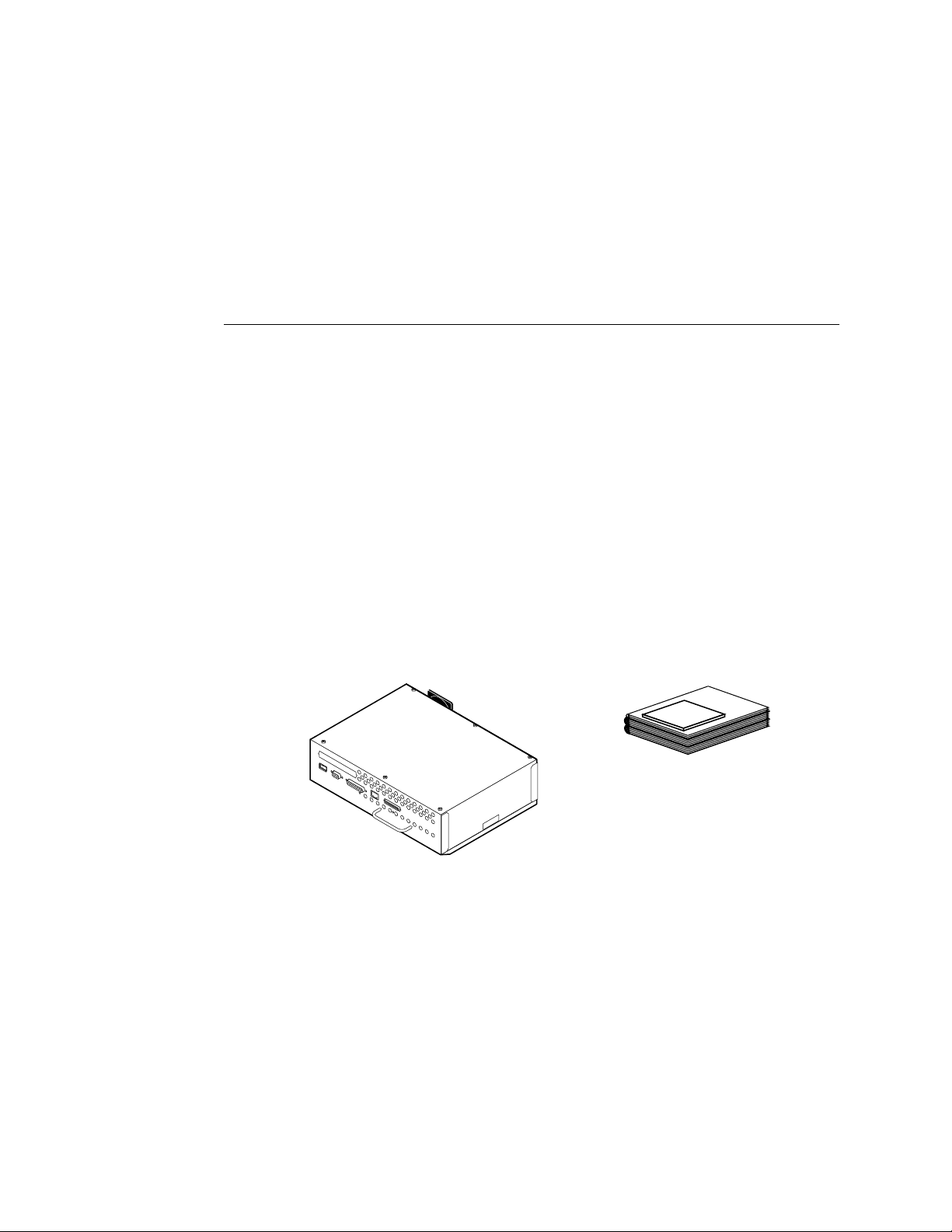
NOTE: The E-700 is assembled and shipped from the factory in a box that includes items
shown in Figure 2-1. The E-700 requires the Controller Interface Type F kit to be
installed. See the installation procedure in Appendix B, “Controller Interface Type F.”
TO UNPACK THE E-700
1. Open the shipping box and remove any packing materials.
2. Remove the contents of the shipping box and inspect them for visible damage.
If you notice shipping damage, have the shipping box ready to show the carrier if
necessary. Call the carrier immediately to report the damage and file a claim, then call
your authorized service/support center. The shipping box includes the following items:
• E-700
• Media package that contains the following:
• User Software CD (see page 1-3 for contents) and Peripheral Manager CD
• User documentation (which includes Getting Started, the Printing Guide,
the Job Management Guide, the Color Guide, the Configuration Guide, and
Release Notes)
• Kodak Color Separation and Gray Scale (small)
Media Package
E-700 assembly
FIGURE 2-1 Contents of shipping box
3. Give the media package to the network administrator.
Let the network administrator know that in order to take full advantage of the E-700, the
user software must be installed on computers that will print to it.
4. Give the Kodak Color Separation and Gray Scale (small) to a person at the customer site
who is responsible for calibration.
2-2
5. Remove any protectors that may be installed on connectors on the E-700.
If a jack is installed in the E-700 RJ-45 connector, grasp the jack with needlenose pliers
and pull it straight out of the connector.
Page 21

Preparing for installation
2
Preparing for installation
Before installing the E-700, do the following:
❑ Test copier functionality.
Copy the copier test page before you install the E-700.
If the copied image indicates that the copier needs adjustment, inform the customer.
After getting approval, complete the copier service needed.
❑ Check the network.
Verify that the network is functioning before you attach the E-700.
• Ask the network administrator to print a document on a shared printer over the
network.
• Ask the network administrator to verify the computer and network requirements as
specified in Getting Started, one of the documents provided in the Media Package.
❑ Install the Controller Interface Type F kit.
See the installation procedure in Appendix B, “Controller Interface Type F.”
Opening the copier
To gain access to the location inside the copier where the E-700 will be installed, you
need to shut down the copier and open the copier from the back.
Follow standard ESD (electrostatic discharge) precautions while handling components.
TO SHUT DOWN THE COPIER
1. Make sure the copier is not in use.
2. At the Control Panel Idle screen, Press the Menu button to access the Functions menu.
3. Use the Down arrow to scroll to Shut Down. Press the Enter button.
4. Use the Down arrow to scroll to Shut Down System. Press the Enter button.
5. Power off the copier using the main power switch on the side.
6. Disconnect the copier power cable from the wall outlet and any external cables.
2-3
Page 22
Installation
2
TO OPEN THE COPIER
1. Shut down the copier (see page 2-3).
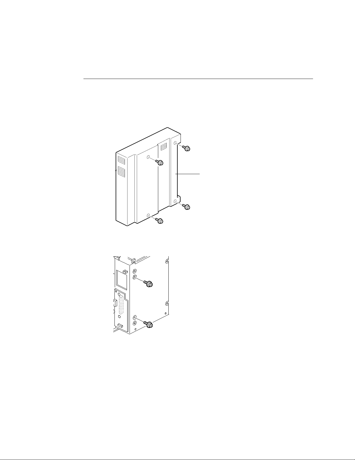
2. Remove the I/F unit cover from the back of the copier (4 screws).
Set aside the I/F unit cover and screws so you can replace them later.
I/F unit cover
FIGURE 2-2 Removing the I/F unit cover
3. Remove and set aside the 2 screws that attach the E-700 to the I/F unit.
F
IGURE 2-3 I/F unit screws
4. Remove the upper shield cover (2 screws) then the right shield cover (6 screws).
Set aside the covers and screws so you can replace them later. For more information and
illustrations, see Appendix B, “Controller Interface Type F.”
The area for the E-700 is now accessible. Make sure the entire Controller Interface Type
F kit is installed before attempting to install the E-700. See Appendix B, “Controller
Interface Type F.”
2-4
Page 23
Opening the copier
2
Installing the E-700 in the copier
TO INSTALL THE E-700
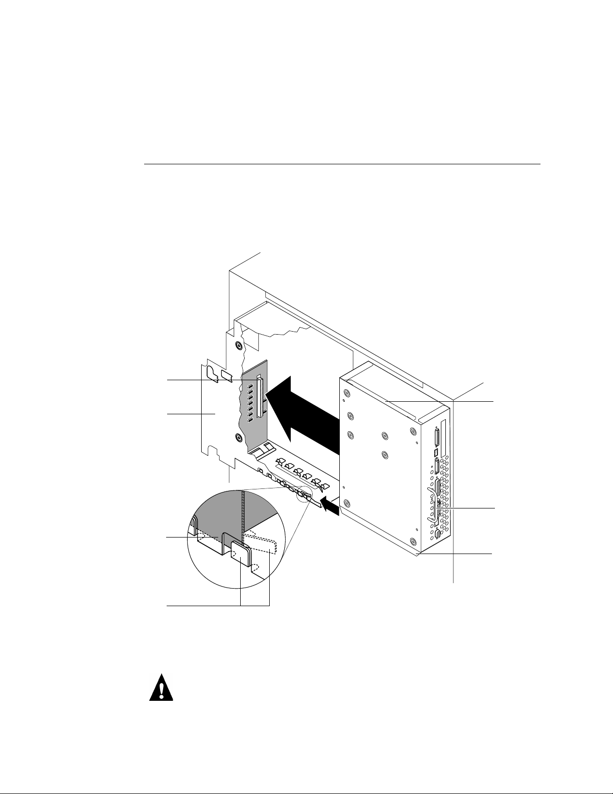
1. Observe the top and bottom slide guides inside the I/F unit and on the outside of the
E-700.
Make sure the slide guides inside the I/F unit have approximately a 30 degree lead-in
angle. If necessary, bend them to create the proper angle (see Figure 2-4 on page 2-5).
Connector in the I/F unit
I/F unit (cutaway view)
E-700 bottom slide guide
I/F unit slide guide
E-700
top slide
guide
Handle
E-700
Bottom slide
guide
FIGURE 2-4 Installing the E-700 in the I/F unit
2. Hold the E-700 by the handle and slide it into the I/F unit, using the slide guides on the
E-700 and inside the I/F unit to align the E-700.
Make sure the E-700 is aligned inside both the top and bottom slide guides. If
misaligned, the copier interface connector on the video interface board can be damaged.
2-5
Page 24
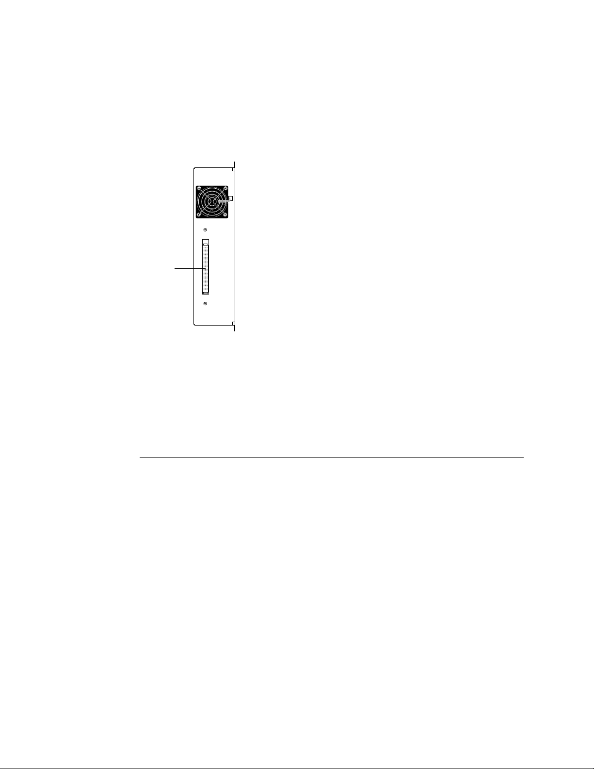
Copier interface connector
Installation
2
3. Push the E-700 until the connector in the I/F unit and the copier interface connector on
the video interface board are securely connected.
F
IGURE 2-5 Copier interface connector
4. Reassemble the copier as described in the following section.
Reassembling the copier
It is recommended that you fully reassemble the copier before you apply power to verify
E-700 functionality.
TO REASSEMBLE THE COPIER
1. Attach the E-700 to the I/F unit with the 2 screws you removed earlier.
For the screw locations, see Figure 2-3 on page 2-4.
2. Replace the right cover shield (6 screws) then the upper shield cover (2 screws) that you
removed earlier.
For more information and illustrations, see Appendix B, “Controller Interface Type F.”
3. Replace the I/F unit cover (4 screws).
See Figure 2-2 on page 2-4.
4. Connect the main power cable to the wall outlet and to the copier.
2-6
Page 25

Reassembling the copier
2
Initial startup
Once the E-700 is installed in the copier, you are ready to start the unit up.
TO STARTUP THE E-700
1. Power on the copier.
2. If the Select Language screen is displayed, display the language of your choice, press the
Enter key, then wait for the Setup screen to be displayed.
The first time the copier is powered on following installation of Controller Interface
Type F components and the E-700 (or following the reinstallation of system software),
you are prompted to select the language to be used for both the E-700 Operation Panel
and special E-700 pages, such as the Configuration page. Use the up and down arrows to
cycle through the languages available.
If you select a different language, the prompt to reboot appears in the language you
selected. Press the Enter key to reboot then wait for the Setup screen to be displayed. To
change the language again, you must reinstall system software.
3. If the Setup screen is displayed, select Server, Printer, Network, and Exit Setup.
Before you can exit Setup, you must first enter Server Setup, Network Setup, and Printer
Setup and save changes. Enter each Setup, press the Cancel key, and when prompted to
save changes, select Yes.
It is the network administrator’s responsibility to configure Setup according to the
network and user environment. At this stage, default settings in Setup are adequate
although they may not be optimal for the user’s environment. Refer the network
administrator to the Configuration Guide for Setup information.
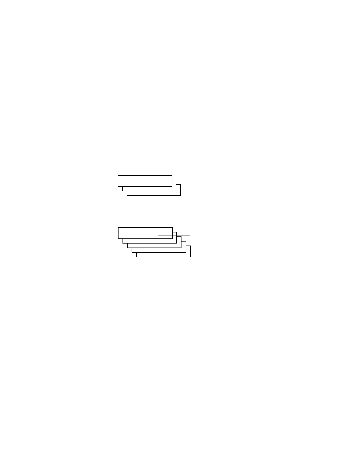
4. Allow the system to proceed to the Info screen to confirm that the E-700 is operating
normally. Scroll down to display E-700 status.
Info
Ready
Server Name
Ready
Ready
1884 MB X.X
Once the E-700 reaches the Info screen, you are ready to print a Test Page and then
connect the E-700 to the network (see “Printing a Test Page” on page 2-8).
2-7
Page 26
Installation
2
Printing a Test Page
Before connecting the E-700 to the network, print a Test Page to verify that the E-700 is
embedded properly in the copier and working. The Test Page is a file that resides on the
E-700 hard disk drive.
TO PRINT A TEST PAGE
1. If the copier is powered off, power it on.
2. Wait while the E-700 and the copier perform their startup sequences.
The E-700 displays the Info screen when ready. The copier beeps when ready. Scroll
down to display E-700 status.
Info
Ready
Server Name
Ready
Ready
1884 MB X.X
3. Press the Menu key to access the Functions screen.
4. Select Print Pages.
Functions
Print Pages
Suspend Print
Resume Print
Run Diagnostics
Reboot Server
5. Select Test Page.
6. Examine the Test Page.
Success in printing the Test Page confirms that the E-700 is functional and connected
properly to the copier. Poor quality may indicate a need to service or adjust the copier,
not the E-700.
Select
2-8
Page 27
Printing the Configuration page
2
Printing the Configuration page
The Configuration page can be helpful during installation, setup, and service. After
installation of the E-700 and before any default settings are changed, you can obtain a
record of the defaults by printing the Configuration page.
After the physical connection to the network is made, the network administrator can
customize Setup options according to the network and user environment. Using the
Configuration page as a guide can help speed up this process. For more information, see
the Configuration Guide.
Before you perform any service procedure, you should print the E-700 Configuration
page, if possible, so that you are prepared to return the settings to their former
configuration, if necessary.
TO PRINT THE CONFIGURATION PAGE
1. If the copier is powered off, power it on.
2. Wait while the E-700 and the copier perform their startup sequences.
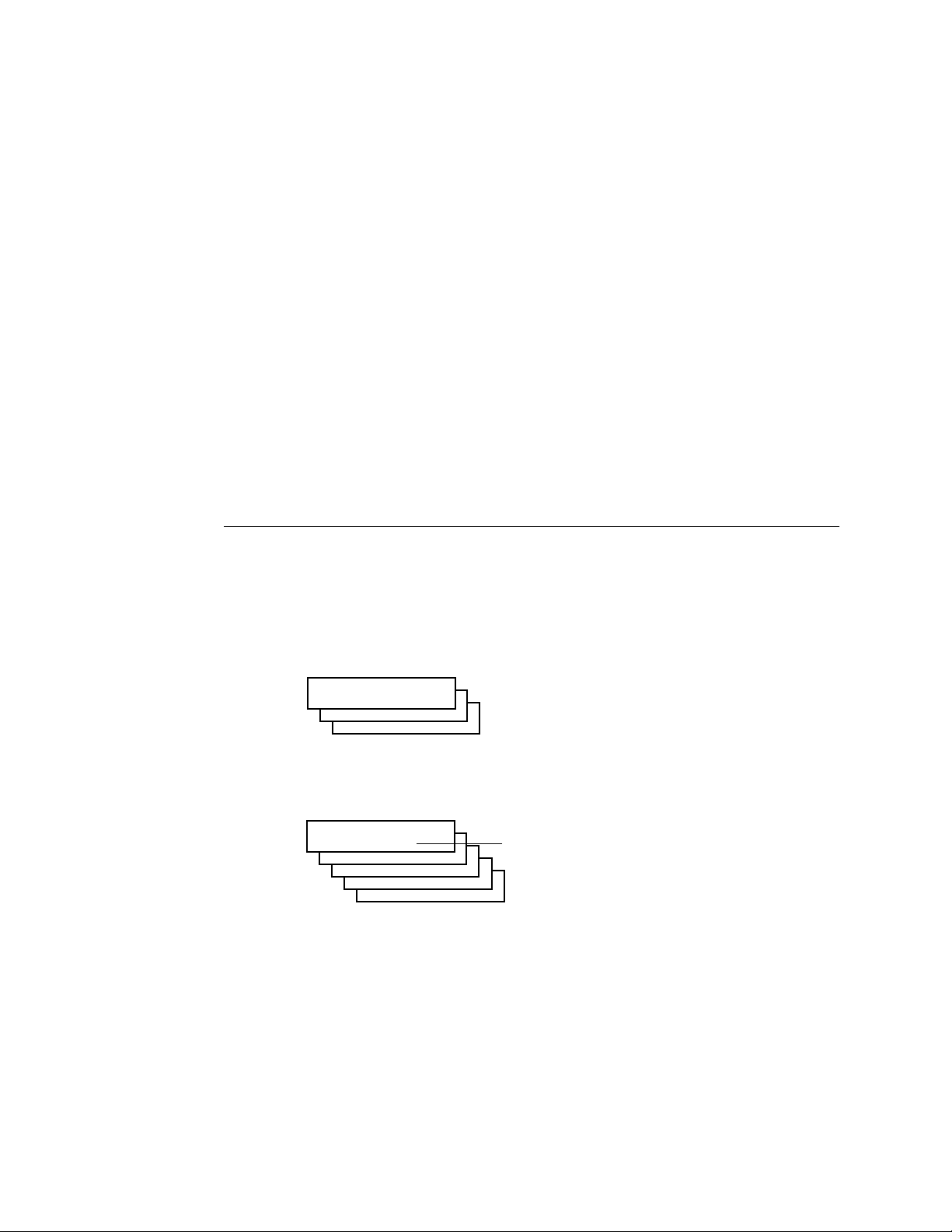
The E-700 displays the Info screen when ready. The copier beeps when ready. Scroll
down to display E-700 status.
Info
Ready
Server Name
Ready
Ready
1884 MB X.X
3. Press the Menu key to access the Functions screen.
4. Select Print Pages.
Functions
Print Pages
Suspend Print
Resume Print
Run Diagnostics
Reboot Server
5. Select Configuration.
6. Save the Configuration page for future reference.
Select
2-9
Page 28

Installation
2
Connecting the E-700 to the network
The E-700 board provides connectivity to an Ethernet network, either thinnet, thicknet,
or twisted pair.
Ethernet network connection
The E-700 board has an external Ethernet 10BaseT/100BaseT RJ-45 connector for
attaching a Category 3 or Category 5 unshielded twisted pair (UTP) network cable
(see Figure 2-6). Category 5 is required for 100BaseT.
10BaseT/100BaseT connector for twisted pair Ethernet
FIGURE 2-6 E-700 network connectors
TO CONNECT A TWISTED PAIR CABLE TO THE E-700
A Category 5 unshielded twisted pair (UTP) network cable must be used for 100BaseT.
It connects to the RJ-45 connector on the E-700.
1. Power off the E-700 before connecting the E-700 to any network device.
2. Connect the network cable to the RJ-45 connector on the E-700.
3. Configure Setup options.
It is the network administrator’s responsibility to configure Setup according to the
network and user environment. Default settings in Setup are adequate although they may
not be optimal for the user’s environment. Refer the network administrator to the
Configuration Guide for Setup information.
4. After configuring Setup options, verify the network connection.
Once the network connection has been made and the E-700 has the correct Setup
configuration and is Ready, the E-700 should be available on the network.
The network administrator should perform any additional network Setup, verify the
network connection, verify that the E-700 appears in the list of printers, and print a few
test documents from a networked computer that will use the E-700.
See the Configuration Guide for more information.
2-10
Page 29
Overview
Chapter 3:
Using the E-700
Operation Panel
3
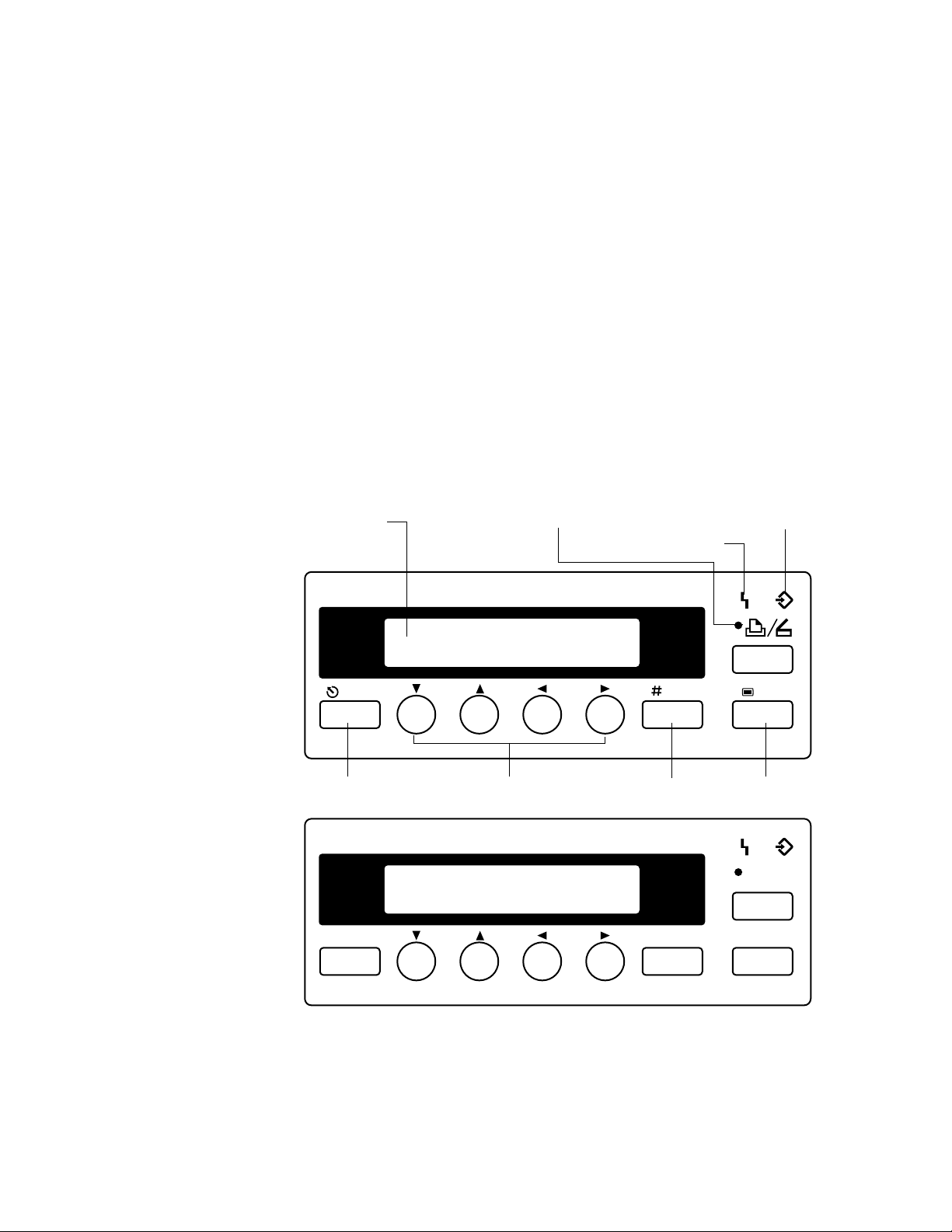
This section describes the functions on the E-700 Operation Panel. The E-700
Operation Panel is an area dedicated to E-700 functions. It is located on the top left side
of the copier Operation Panel. The keys on the E-700 Operation Panel allow you to
access and monitor different features of the E-700. This guide does not attempt to
describe all functions of the Operation Panel, only those functions that pertain to the
E-700. For information on installing the E-700 Operation Panel, see the installation
procedure in Appendix B, “Controller Interface Type F.”
Overview
Current status and Setup information are displayed on the E-700 Operation Panel. Print
activity can be monitored in the display window and specific E-700 functions (such as
printing a Test Page) are controlled using the keys on the E-700 Operation Panel. Three
LEDs assist in providing status information.
Printing/processing LEDPrinter/Scanner LED and keyDisplay Window
Error LED
Arrow keysCancel key Enter key Menu key
Printer/
Scanner
Cancel Enter # Menu
FIGURE 3-1 E-700 Operation Panel (International and U.S. models)
3-1
Page 30
Using the E-700 Operation Panel
3
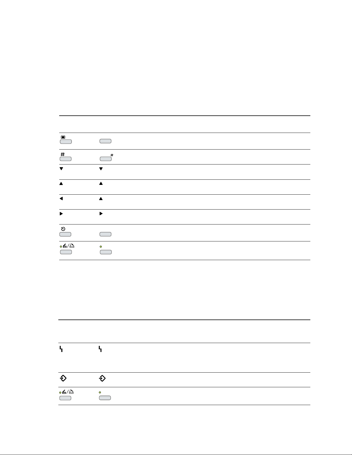
Keys
Once the E-700 board is installed in the copier, use the E-700 keys on the Operation
Panel to perform the following functions:
Key
(International)
Key
(U.S.)
Menu
Enter
Cancel
Printer/
Scanner
Activity indicators
Description
From the Info screen, display the Functions screen when idle and the run-time
screen when a job is in process.
Select the currently displayed menu item and proceed to the next screen. Cancel a
job from the printing or processing screen.
Scroll down the screen to display menu items or part of a text message. After the
bottom of the screen is reached, the top of the screen is displayed.
Scroll up the screen to display the previous menu item or part of a text message.
When the top of the screen is reached, the bottom of the screen is displayed.
Backspace the cursor to the text-entry position to the left. In a text field, it deletes
the character to the left.
Advance the cursor to the text-entry position to the right.
In the menus, return to previous level.
Switch from copier mode to Printer/Scanner mode. See the Copier service manual
for information.
3-2
Activity
indicator
(International)
Once the E-700 board is installed in the copier, the red and green activity lights on the
E-700 Operation Panel turn on and stay solid or flash on and off to indicate the
following:
Activity
indicator
(U.S.)
Printer/
Scanner
Description
• Flashing red—An error prevents the E-700 from processing a job (see the
Printing Guide for more information).
• Solid red (more than 30 seconds)—A communication error has occurred
between the E-700 and the copier.
• Flashing green—The E-700 is processing a job or communicating with a
remote computer.
• Solid green—The E-700 is using the copier to print or scan a job.
Page 31
Screens
3
Screens
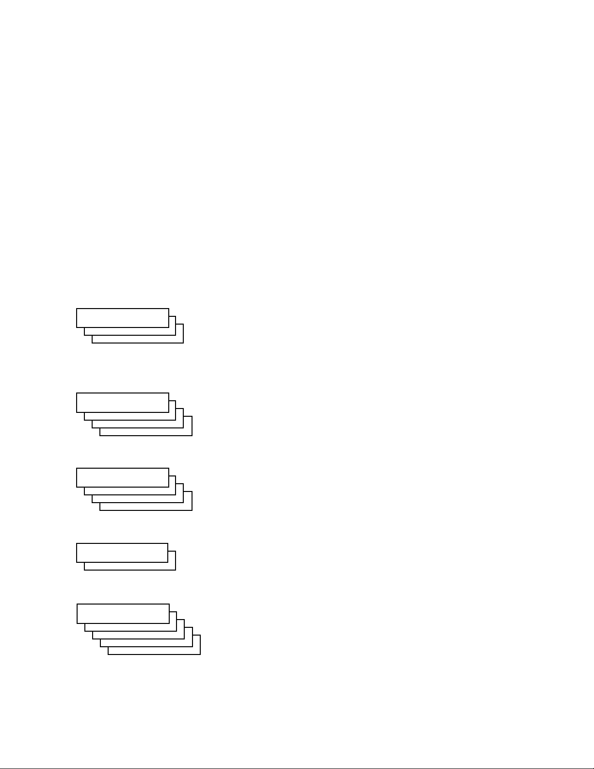
When the copier is idle, E-700 status information and functions available from the
E-700 Operation Panel. You can monitor print activity, control E-700 functions, and
access the E-700 Setup menus.
When a job is sent to the copier, the E-700 Operation Panel cycles through the RIP and
Print screens, and then displays the Info screen. If an error occurs, the Alert screen is
displayed with a message describing the error. A Startup screen is also available It is made
available when the system is powered on or when you reboot the system. It has options
for setting up the printer, rebooting the E-700, and installing system software.
These screens contain the following information:
Info status screen
Info
Server Name
Ready
Ready
Ready
1884 MB X.X
RIP status screen Appears when a job is being processed. Displays the name of the file, the name
RIP
Cancel Job
doc.eps
Jack D.
Busy ####K
The first line of this screen displays the printer’s name on the network. Scrolling
down displays the status of the E-700, the amount of disk space available on the
hard disk drive, and the current system software version. Normally, if no jobs
are currently being processed or printed, the Info screen displays Ready (a job
may be between processing and printing). The Info screen is the default screen.
Press the Menu key to display the Functions screen.
of the user who sent the job, the status, and the amount of the job in kilobytes
that has been processed so far. To cancel the job, display Cancel Job and press
the Enter key. Press the Cancel key to display the Functions screen.
Print status screen Appears when a job is being printed. Displays the name of the user who sent the
job, the number of copies printed so far, and the number of copies requested.
Print
Cancel Job
Jane D.
Copies: 1/100
R4
Alert screen Displays a message if an error or other Alert condition arises. Pressing the down
Alert
Warming up
R4
Functions screen Gives you access to administrative functions not normally performed from a
Functions
Print Pages
Suspend Print
Resume Print
Run Diagnostics
Reboot Server
To cancel the job, display Cancel Job and press the Enter key. Press the Cancel
key to display the Functions screen.
arrow key may be necessary to view the entire error message. If other screens are
being accessed, the Alert screen is redisplayed frequently until the condition is
resolved. Press the Cancel key to display the Functions screen.
remote workstation (see “Functions screen” below for information on the
available functions). Press the Cancel key to display the Info screen.
3-3
Page 32

Using the E-700 Operation Panel
3
Functions screen
The Functions screen allows you to perform a variety of administrative functions that do
not affect print jobs of other users. Use the up and down arrow keys to scroll through the
menu items. Press the Enter key to select the menu item displayed. Press the Cancel key
or do nothing to return to the Info screen. The following options are available from the
Functions screen:
Print Pages—Enables you to print special pages from the copier:
• Test Page—Prints the Test Page resident on the E-700 hard disk drive. The Test
Page confirms that the E-700 is properly installed in the copier and allows you
to view information about color and grayscale to troubleshoot E-700 functions.
Test Page information includes but may not be limited to: Server name, Printer
name, Calibration, Measurements, Target, Date & Time, CMYK Simulation,
RGB Source, Rendering Style, Color Mode. For more information see the
Printing Guide and the Configuration Guide.
• Configuration—Prints the current device configuration, including information
about all current Setup settings, calibration profile, and the Ethernet address of
the E-700 board.
• Job Log—Prints the log of the last 55 jobs. For more information about the job
log, see the Printing Guide.
• Menu Map—Prints the E-700 Menu Map, useful when navigating through the
different E-700 Setup screens.
• Color Charts—Prints the color reference charts, including swatches of the RGB,
CMY, and Pantone colors available from the E-700.
• Font List—Prints a list of all the fonts resident on the E-700 hard disk drive.
Suspend Printing— This option interrupts the current print job so you can use the copier
to make copies. If it has not finished processing, the RIP will continue but the job will
not print. You can then select Resume Printing.
Resume Printing—Resumes printing after interrupting the print job in order to make
copies.
Run Diagnostics—Select this option to access:
• Video Diagnostics— Runs diagnostics on the E-700 video interface
(see “Video board diagnostics” on page 5-7).
Reboot Server—Shuts down all printing activity properly and then restarts the E-700.
Access to E-700 Setup options are made available at this time.
3-4
Page 33

Screens
3
Startup screen
• The Startup screen is made available when you reboot the system from the Functions
screen or when you power on the copier. The following options are available from the
Startup screen.
Start Up
Ready
Run Setup
Ready
Start System
Start Up
Reboot System
Install Software
• Run Setup—allows you to access E-700 Setup options in order to configure the
network and printing environment. Typically it is the network administrator’s
responsibility to configure Setup according to the network and user environment.
Setup is required the first time the copier is powered on after new E-700 system
software is installed. You must enter and save changes to Server, Network, and Printer
Setup after installing system software.
Setup options include: Server, Network, Printer, PS Setup, Color Setup, Job Log
Setup, Calibration, Change Password, and Clear Server. See the Configuration Guide
for detailed information on Setup.
NOTE: Make sure the network administrator is available to customize Setup options
according to the network and user environment.
• Start System—Exits the Start Up screen and displays the Info screen.
• Reboot System—Shuts down all E-700 activity in the correct manner and restarts the
E-700. Press the Enter key to reboot the E-700. Once the server reboots you can access
Setup options.
3-5
Page 34

Page 35

Overview
Chapter 4:
Service
Procedures
4
Generally, the Color Controller E-700 does not require regular maintenance. Use the
procedures in this chapter to inspect, remove, reseat, or replace major hardware
components and also to install system software.
Overview
This chapter includes information on the following:
• Cable connections (page 4-5)
• E-700 board (page 4-8)
• E-700 board components
• Video interface board (page 4-12)
• SCSI interface board (page 4-14)
• DIMMs (page 4-15)
• Battery (page 4-16)
• CPU fan (page 4-17)
• Exhaust fan (page 4-18)
• Hard disk drive (page 4-19)
• System software (page 4-24)
For information on how to remove and replace the I/F unit that encloses the E-700, see
the installation procedure in Appendix B, “Controller Interface Type F.”.
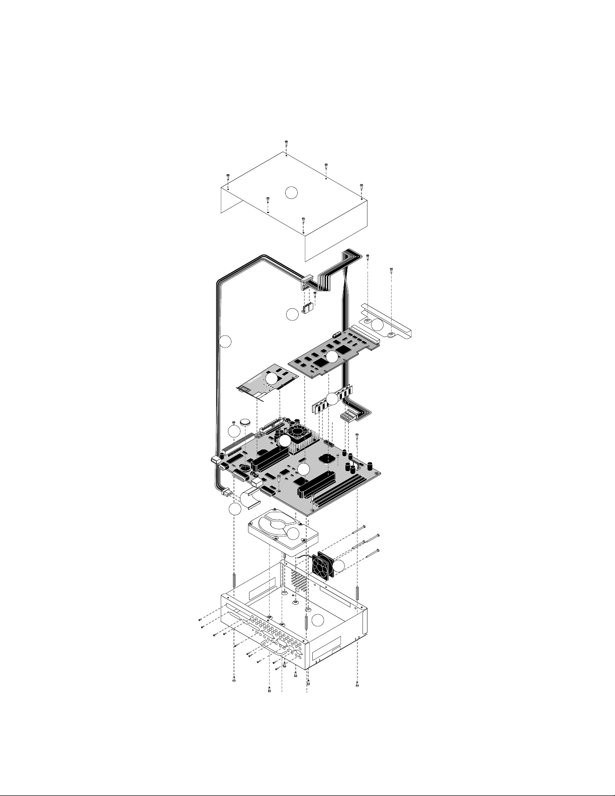
See Figure 4-1 on page 4-2 for an overview of E-700 board components. Replacement
parts are available from your authorized service representative.
When performing the procedures described in this chapter, see “Precautions” on page xiii
and “Tools you will need” on page xiv.
The E-700 system software is installed on the hard disk drive at the factory. You will need
to re-install system software if you:
• Replace the hard disk drive
• Upgrade to a more recent version of the system software
4-1
Page 36
Service Procedures
4
Key
1. Pan cover
2. Middle power supply cable connector
3. Power supply cable
1
2
3
5
4. SCSI interface board
5. Video interface board
6. Video interface board bracket
7. DIMMs
8. CPU fan
9. Battery
10. E-700 board
11. HDD
12. HDD cable
13. Exhaust fan
14. Pan
6
12
4
7
9
8
10
11
13
14
4-2
IGURE 4-1 Exploded view of E-700
F
Page 37
Accessing the E-700
4
Accessing the E-700
Always use the following procedures when accessing the E-700. Make sure you attach an
ESD grounding wrist strap and follow standard ESD (electrostatic discharge) precautions
before following this procedure.
TO SHUT DOWN THE COPIER
1. Make sure the copier is not in use.
2. At the Control Panel Idle screen, Press the Menu button to access the Functions menu.
3. Use the Down arrow to scroll to Shut Down. Press the Enter button.
4. Use the Down arrow to scroll to Shut Down System. Press the Enter button.
5. Power off the copier using the main power switch on the side.
6. Disconnect the copier power cable from the wall outlet and any external cables.
TO ACCESS THE E-700
1. Shut down the copier as described above.
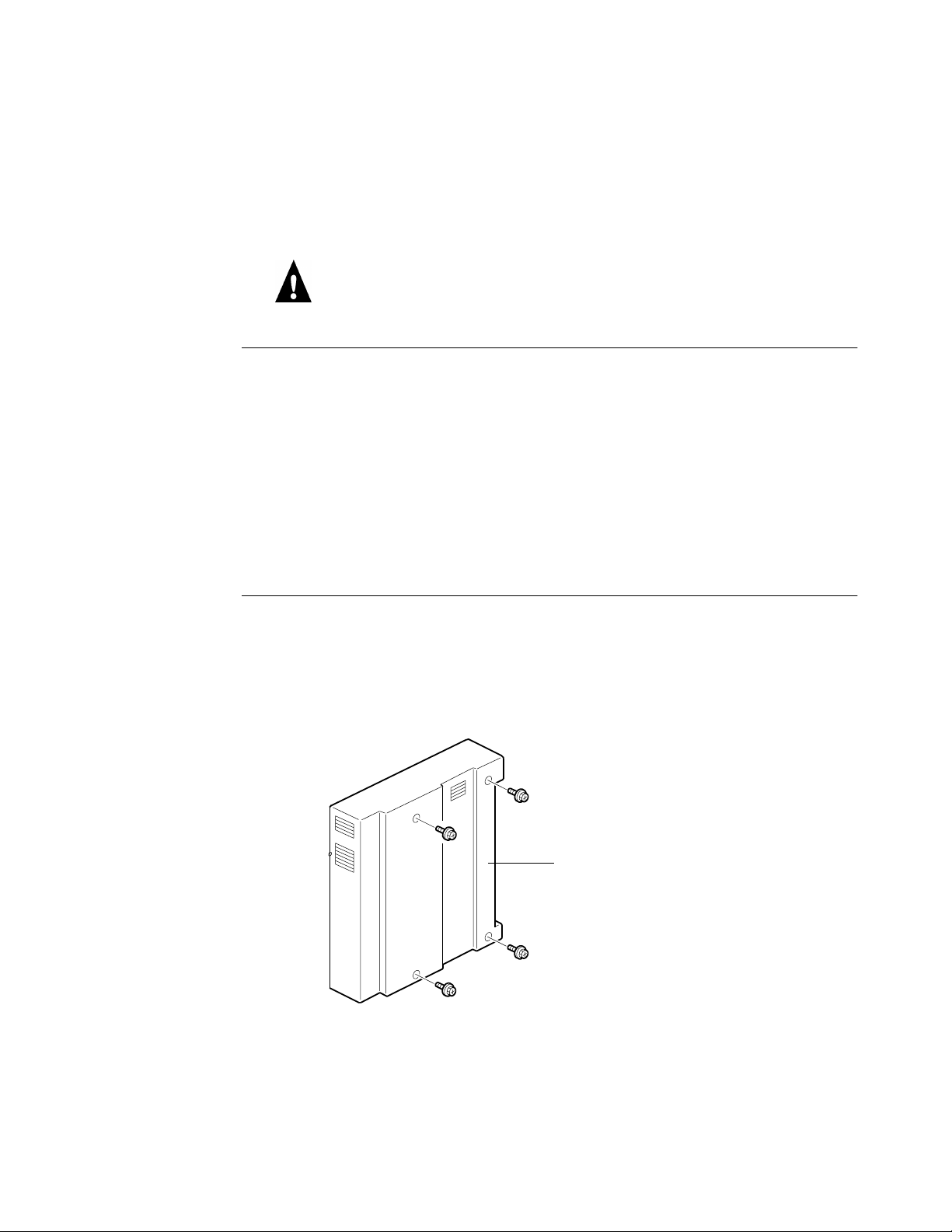
2. Remove the I/F unit cover from the back of the copier (4 screws).
Set aside the I/F unit cover and screws so you can replace them later.
I/F unit cover
FIGURE 4-2 Removing the I/F unit cover
3. Remove the upper shield cover (2 screws) then the right shield cover (6 screws).
Set aside the covers and screws so you can replace them later. For more information and
illustrations, see Appendix B, “Controller Interface Type F.”
4-3
Page 38
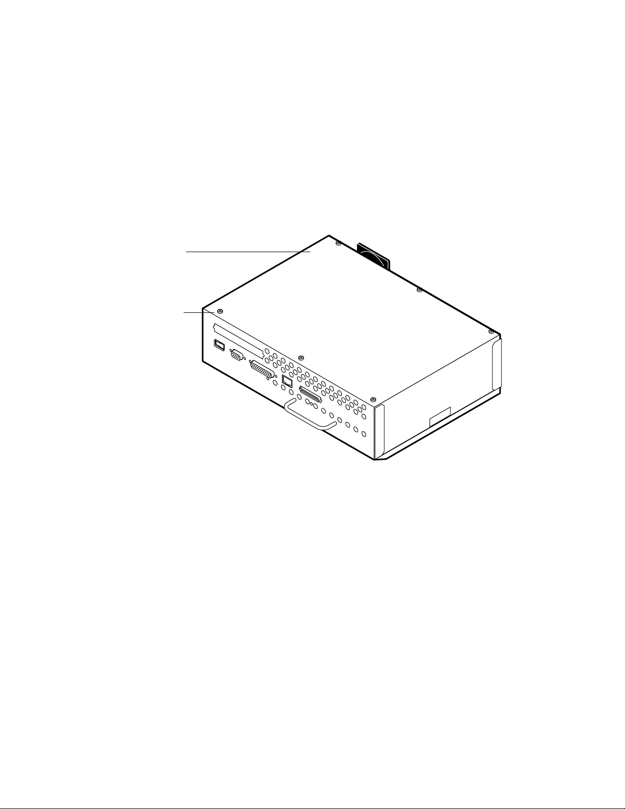
Pan cover
Screw
Service Procedures
4
4. Remove the 2 screws that attach the E-700 to the I/F unit.
Set aside the screws so you can replace them later.
5. Use the handle to pull out the E-700 from the I/F unit.
Set the E-700 on a stable static-free surface.
6. Remove the six screws that secure the pan cover. Lift off the pan cover and set it aside.
4-4
F
IGURE 4-3 Removing the pan cover
The E-700 components are now accessible.
Page 39

Checking E-700 internal connections
4
Checking E-700 internal connections
The most common causes of hardware problems are faulty and loose connections.Before
you conclude that any board or component has failed, remove, inspect, and reseat all
appropriate connections, and then verify that the problem still occurs.
TO CHECK BOARD AND CABLE CONNECTIONS
1. Before you touch any parts inside the E-700, attach a grounding wrist strap. Touching
the pan also discharges static electricity.
2. Place the E-700 so the internal components of the E-700 are facing up.
3. Make sure the DIMMs are properly installed (see “To replace a DIMM” on page 4-15 for
the proper procedure).
4. Make sure the battery is properly installed (see “To replace the battery” on page 4-16).
5. Make sure the video interface board is properly installed (see “To replace the video
interface board” on page 4-13).
6. Inspect the copier interface connector on the video interface board.
If any pins are pushed in or bent, gently fix them with a pair of small needlenose pliers.
7. Make sure the SCSI interface board is properly installed (see “To replace the SCSI
interface board” on page 4-14)
8. Inspect the HDD cable to make sure it is intact.
Faulty ribbon cables are easily overlooked. Check the contact point between the cable
and the connector to ensure that they have not separated. If a ribbon cable is suspect,
substitute it with a tested cable.
9. Check the fan cables of the exhaust fan and the CPU fan.
Make sure the cables are intact. Also, check airflow direction. When the fans are installed
properly:
• An arrow on the exhaust fan points away from the E-700
• An arrow on the CPU fan points to the CPU
10. Make sure the power cable is intact and properly connected to the HDD, video interface
board, and E-700 board.
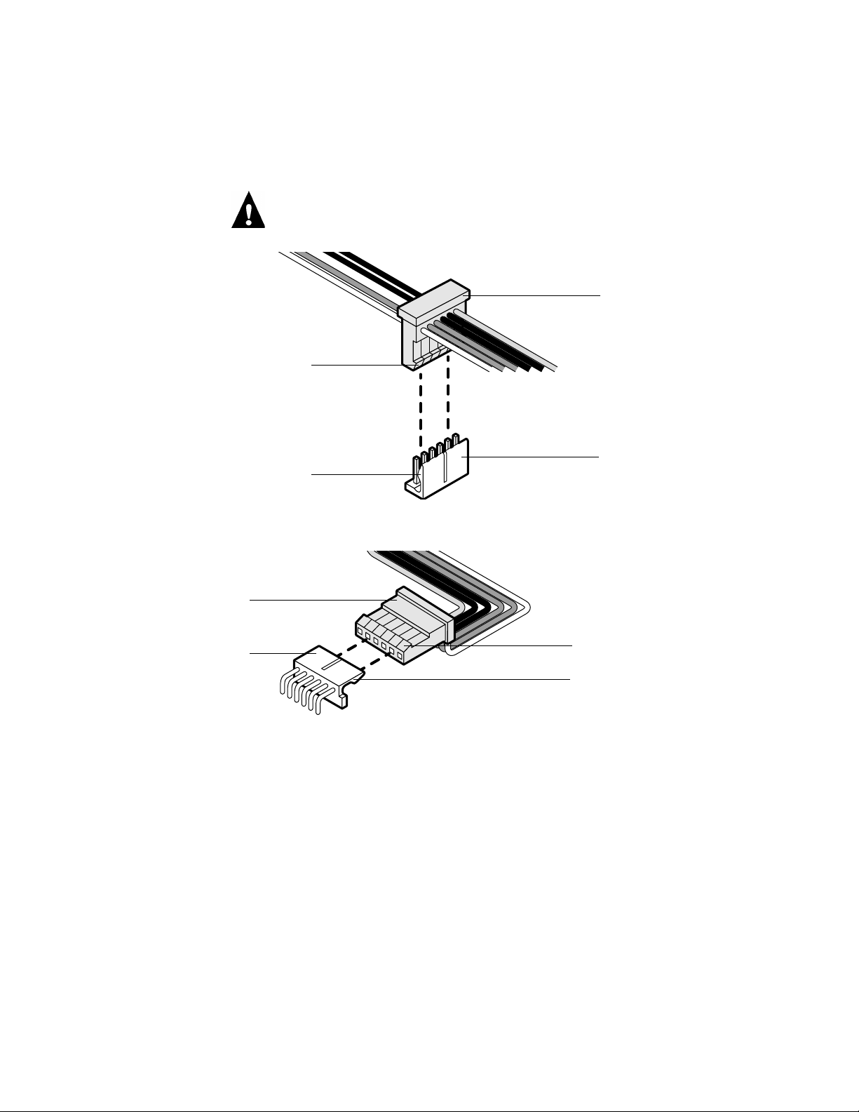
The power cable has 3 connectors. For the best fit inside the chassis, the middle
connector is attached to the video interface board and the 6-wire end connector is
attached to the E-700 board. The 4-wire end connector (to the HDD) is keyed, however,
the connectors to the video interface board and the E-700 board are not keyed.
4-5
Page 40
Service Procedures
4
Make sure the connectors to the video interface board and the E-700 board are installed
so that the lip of the connector fits under the ridge of the board connector. If oriented
backwards, the boards can be damaged. See the figures below.
Middle connector
Lip
Power connector on
Ridge
video interface
board
End connector
Power connector on
E-700 board
FIGURE 4-4 Power cable middle connection
Lip
Ridge
FIGURE 4-5 Power cable end connection
4-6
Page 41

Replacing parts of the E-700
4
Replacing parts of the E-700
The E-700 board has a 366MHz Intel Celeron CPU. The E-700 board provides the
Ethernet networking interface, controls hard disk drive functions, and handles the
communication between the E-700 and external devices. With its video interface board it
controls the video image data transferred to and from the copier.
When replacing any of its components, make sure to protect the E-700 board from
excessive bending and flexing. When possible, remove the E-700 board from the pan and
remove the standoffs from the board’s corners and lay the E-700 board flat before
servicing.
Following are instructions for accessing, removing, and replacing the following parts of
the E-700:
• E-700 board
• E-700 board components including
• Video interface board
• SCSI interface board
• DIMMs
• Battery
• CPU fan
• Exhaust fan attached to the pan
•HDD
Make sure you attach an ESD grounding wrist strap and follow standard ESD
(electrostatic discharge) precautions before following this procedure.
4-7
Page 42
4
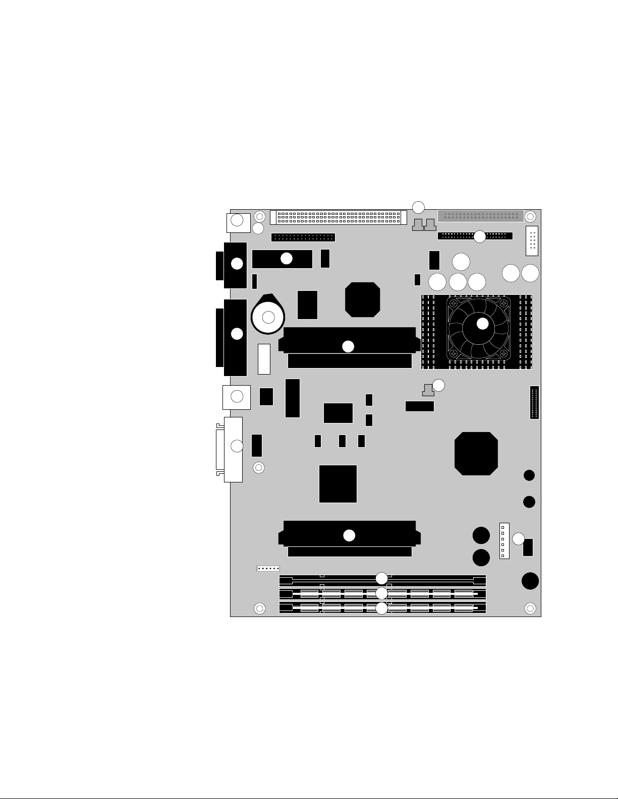
Key
15. Not used
16. DB-9 connector (J1)
17. Not used
18. Ethernet connector (J4)
19. Parallel connector (J2)
20. SCSI interface board connector(J17)
21. Video interface board connector
(J16)
22. DIMM socket (U52)
23. DIMM socket (U51)
24. DIMM socket (U50)
25. Power supply cable connector (J20)
26. CPU
27. HDD cable connector (J36)
28. CPU fan cable connector (J27)
29. Exhaust fan cable connector (J25)
30. BIOS socket (U17)
31. Battery (BT)
NOTE: Connectors and components
not listed are not used.
Service Procedures
E-700 board
The E-700 board is installed in the pan on four standoffs. This section includes
instructions for replacing the E-700 board and E-700 board components.
15
1
13
17
16
12
6
14
2
3
4
5
FIGURE 4-6 E-700 board layout
7
8
9
10
11
4-8
Page 43
Replacing parts of the E-700
4
TO REMOVE THE E-700 BOARD
1. Shut down the copier and access the E-700 as described on page 4-3.
2. Remove the video interface board from E-700 board connector J17 (see page 4-12).
3. Remove the SCSI interface board from board connector J16 (see page 4-14)
4. Remove the connector bracket from the pan (see Figure 4-1 on page 4-2). Set the two
screws and the connector bracket aside so you can replace them later.
5. Remove the support bracket from the pan (see Figure 4-1 on page 4-2). Set the two
screws and the support bracket aside so you can replace them later.
6. Remove the exhaust fan cable from E-700 board connector J25 (see “Exhaust fan” on
page 4-18).
7. Remove the HDD cable from E-700 board connector J36.
Using a ribbon cable connector extractor is recommended.
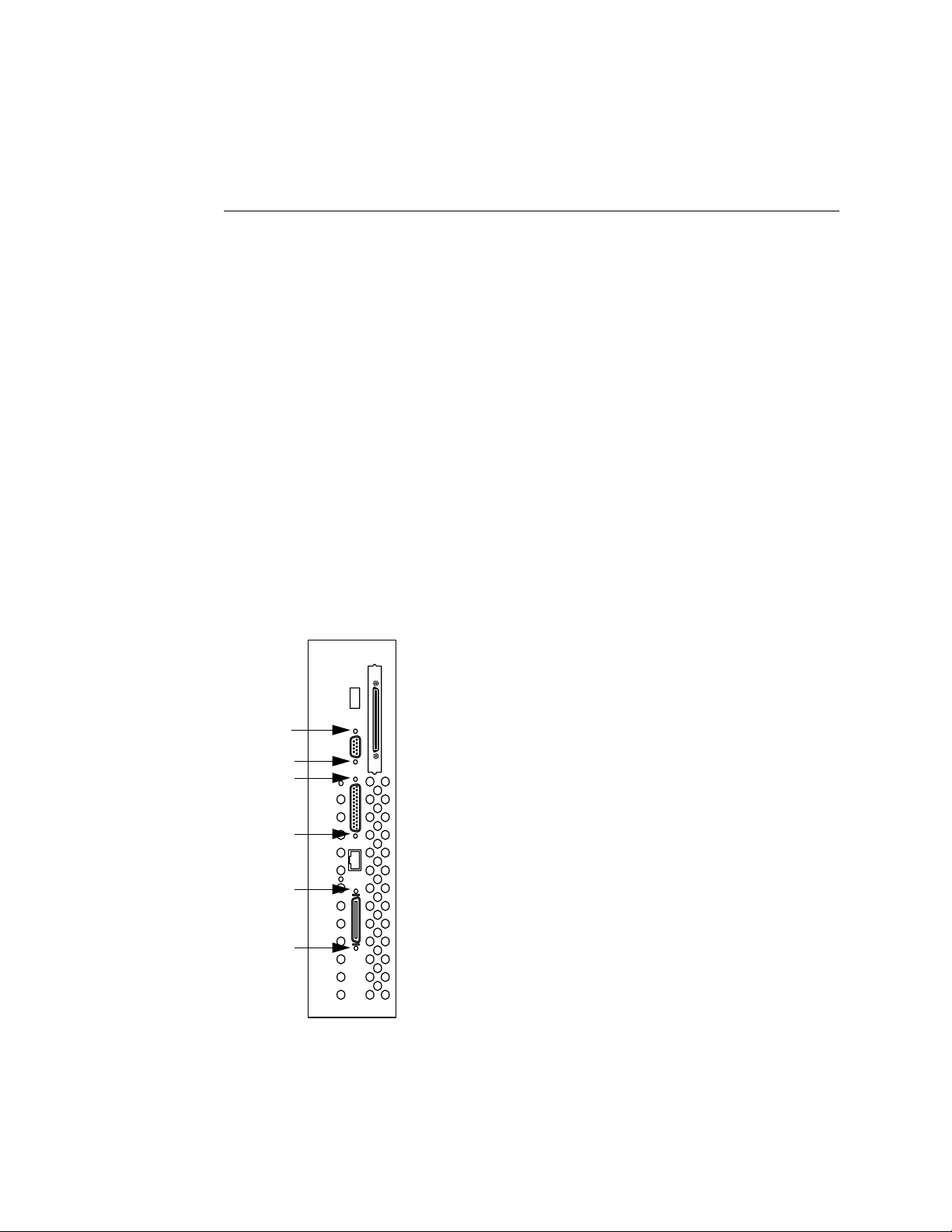
8. Remove the screws on the face plate that secure the board connectors to the face plate
as shown below.
Make sure to keep each set of screws together.
NOTE: Use a #1 Phillips screwdriver for the SCSI
connector and the parallel connector.
NOTE: Use a 3/16" hex nut driver to remove the standoffs
on the 9-pin D connector and the 25-pin D connector.
FIGURE 4-7 External E-700 connectors
4-9
Page 44

Service Procedures
4
9. Remove and set aside the four screws that secure the E-700 board to the standoffs.
10. Remove the power cable from E-700 board connector J16.
Lift the E-700 board off the standoffs and carefully tilt it out of the pan to access the
power cable.
11. Completely remove the E-700 board from the pan. Place the board on a stable antistatic
work surface or into an antistatic bag.
Tilt the board as necessary to make sure the connectors clear the pan as you remove the
board.
TO REPLACE THE E-700 BOARD
NOTE: To make sure the copier interface connector (on the video interface board) is
properly aligned, make sure not to tighten screws until all components are in place.
1. Place the E-700 board inside the pan so the external connectors fit into the pan cutouts.
2. Connect the end connector of the power cable to E-700 board connector J16.
Make sure the HDD is already installed with both cables attached. From the HDD,
route the power cable between the pan and the pan standoff. Carefully tilt the E-700
board to make the connection.
Improper connection of the power cable can damage the E-700. See “Checking E-700
internal connections” on page 4-5 including Figure 4-5 on page 4-6.
3. Align the E-700 board with the pan standoffs and then replace the four mounting screws
into the pan standoffs.
4. Insert the screws (and washers, if present), and standoffs that attach the external
connectors to the pan (see Figure 4-7 on page 4-9).
Use a 3/16" hex nut driver to install the standoffs on the 9-pin D connector and the
25-pin D connector. Use a #1 Phillips screwdriver for the SCSI connector and the
parallel connector.
5. Connect the HDD cable to E-700 board connector J36.
6. Connect the exhaust fan cable to E-700 board connector J25.
7. Attach the support bracket to the pan (see Figure 4-1 on page 4-2) using the two screws
you removed earlier.
8. Attach the connector bracket to the pan (see Figure 4-1 on page 4-2) using the two
screws you removed earlier.
Make sure that the connector bracket is flat against the inside of the pan and the two
mounting holes are aligned with the screw holes in the pan.
4-10
9. Install the video interface board in E-700 board connector J17 (see page 4-12).
Page 45

Replacing parts of the E-700
4
10. Install the SCSI interface board in board connector J16 (see page 4-12)
11. Reassemble the copier and verify functionality as described in “Restoring E-700
functionality after service” on page 4-22.
12. If you replaced the E-700 board with a new one, install system software
(see page 4-24). If a startup error occurs when you power on the copier, check E-700
connections. If a startup error still occurs, call your authorized service/support center.
4-11
Page 46
Copier interface
connector
connects to I/F
unit
Service Procedures
4
Video interface board
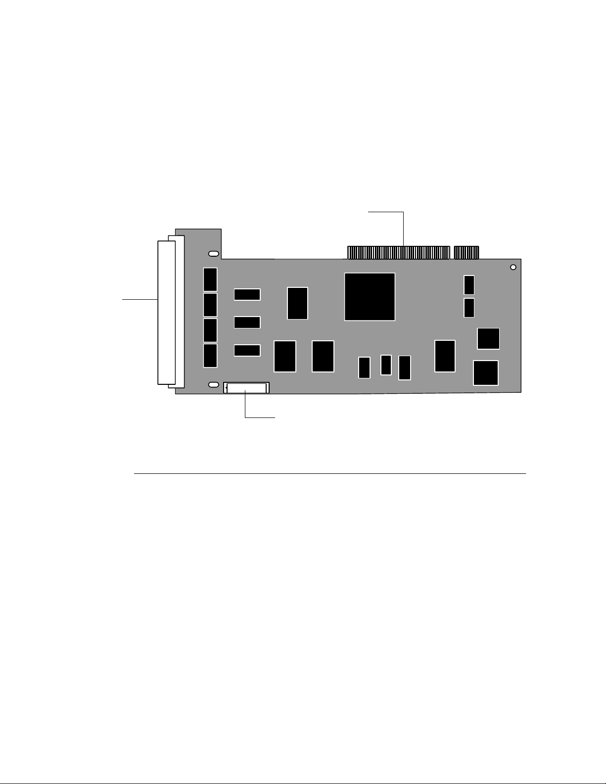
The video interface board provides the interface between the E-700 and the copier. It
connects to video interface connector J17 on the E-700 board and to the connector in
the I/F unit (see Figure 4-8 and Figure 2-4 on page 2-5).
To E-700 board connector J17
Power connector J2 connects to power supply cable
FIGURE 4-8 Video interface board layout
TO REMOVE THE VIDEO INTERFACE BOARD
1. Shut down the copier and access the E-700 as described on page 4-3.
2. Remove the power cable from video interface board connector J2.
3. Remove and set aside the one screw that attaches the video interface board to the
support bracket (for its location, see Figure 4-1 on page 4-2).
4. Remove and set aside the two screws that attach the video interface board to the
connector bracket (for its location, see Figure 4-1 on page 4-2).
5. Gently remove the video interface board from E-700 board connector J17.
Grasp the board at the sides. Gently pull the board straight out of the connector.
6. Carefully tilt the video interface board out of the pan.
7. Place the board in an anti-static bag.
4-12
Page 47

Replacing parts of the E-700
4
TO REPLACE THE VIDEO INTERFACE BOARD
NOTE: To make sure the copier interface connector is properly aligned, make sure not to
tighten screws until all components of the E-700 are in place.
1. Remove the board from the anti-static bag.
2. Carefully tilt the video interface board into the pan and insert the video interface board
into E-700 board connector J17.
Grasp the board at the sides. Gently push the board straight into the connector. Check
the visible portion of the gold fingers of the connector on the video interface board to
determine if the connection is aligned properly and secure.
3. Align the mounting hole in the video interface board with the hole in the connector
bracket and attach the video interface board to the connector bracket (see Figure 4-1 on
page 4-2) using the two screws you removed earlier.
4. Align the mounting hole in the video interface board with the hole in the support
bracket and attach the video interface board to the support bracket (see Figure 4-1 on
page 4-2) using the one screw you removed earlier.
5. Connect the middle connector of the power cable to video interface board connector J2.
To avoid bending and flexing the video interface board, firmly seat the cable connector
by pressing from the bottom of the board as you press the cable connector into J2.
Improper connection of the power cable can damage the E-700. See “Checking E-700
internal connections” on page 4-5 including Figure 4-5 on page 4-6.
6. Reassemble the copier and restore functionality as described on page 4-22.
When you reassemble the E-700, you will tighten all screws completely.
4-13
Page 48
Connects to an external
CD-ROM drive
Service Procedures
4
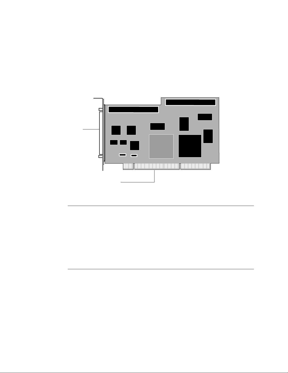
SCSI interface board
The SCSI interface board provides the interface between the E-700 and an external
CD-ROM drive or other external SCSI device. It connects to video interface connector
J16 on the E-700 board (see Figure 4-8 and Figure 2-4 on page 2-5).
To E-700 board connector J16
FIGURE 4-9 SCSI interface board layout
TO REMOVE THE SCSI INTERFACE BOARD
1. Shut down the copier and access the E-700 as described on page 4-3.
2. Gently remove the SCSI interface board from E-700 board connector J16.
Grasp the board at the sides. Gently pull the board straight out of the connector.
3. Carefully lift the SCSI interface board out of the pan.
4. Place the board in an anti-static bag.
TO REPLACE THE SCSI INTERFACE BOARD
1. Remove the board from the anti-static bag.
2. Insert the SCSI interface board into E-700 board connector J16.
Grasp the board at the sides. Gently push the board straight into the connector. Check
the visible portion of the gold fingers of the connector on the video interface board to
determine if the connection is aligned properly and secure.
4-14
3. Reassemble the copier and restore functionality as described on page 4-22.
When you reassemble the E-700, you will tighten all screws completely.
Page 49
Replacing parts of the E-700
4
DIMMs
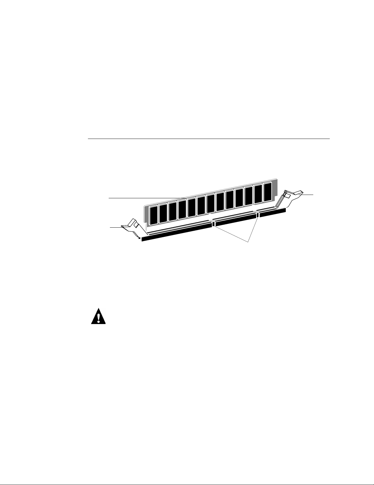
There are three DIMM sockets on the E-700 board: U52, U51, and U50. Each DIMM
(dual in-line memory module) is held in place by levers at each end of its socket on the
E-700 board.
NOTE: Approved DIMMs are available from your authorized service representative.
TO REPLACE A DIMM
1. To release a DIMM, push outward on the lever on each side of the DIMM.
See the following figure.
DIMM
Lever
Socket notches
FIGURE 4-10 Releasing a DIMM
2. Slide the DIMM out of the socket.
3. To install a DIMM, slide it into the socket until the levers snap into place.
The DIMM fits the socket only one way. The two notches on the bottom of the DIMM
should line up with the notches in the socket.
To avoid bending and flexing the E-700 board, firmly seat the DIMM by pressing from
the bottom of the E-700 board as you press the DIMM into its socket.
Make sure that the levers close securely around the ends of the DIMM and that the
DIMM is fully seated in its socket.
4. Reassemble the copier and verify functionality as described in “Restoring E-700
functionality after service” on page 4-22 or other documentation.
Lever
5. Print a Configuration page to verify the amount of memory.
4-15
Page 50

Service Procedures
4
Battery
The battery on the E-700 board is located at BT. To replace it, use a 3V manganese
dioxide lithium coin cell battery (Panasonic CR2032 or equivalent).
CAUTION: There is danger of explosion if the battery is replaced with the incorrect
type.Replace only with the same type recommended by the manufacturer. Dispose of
used batteries according to the manufacturer's instructions.
ACHTUNG: Es besteht Explosionsgefahr, wenn die Batterie durch eine Batterie falschen
Typs ersetzt wird. Als Ersatz dürfen nur vom Hersteller empfohlene Batterien gleichen
oder ähnlichen Typs verwendet werden.Verbrauchte Batterien müssen entsprechend den
Anweisungen des Herstellers entsorgt werden.
ATTENTION: Il y a risque d'explosion si la pile est remplacée par un modèle qui ne
convient pas. Remplacez-la uniquement par le modèle recommandé par le constructeur.
Débarrassez-vous des piles usées conformément aux instructions du constructeur.
TO REPLACE THE BATTERY
1. Locate the battery on the E-700 board (see Figure 4-6 on page 4-8).
2. Carefully lift up the clip that holds the battery.
Use caution when lifting up the clip; excessive force could cause the clip to lose its
tension.
Clip
+
FIGURE 4-11 E-700 battery
3. Pull the battery out of its socket and release the clip.
4. To insert a new battery, slide the battery into the socket under the clip with the positive
(+) side facing up.
Make sure the clip holds the battery securely in the socket.
5. Reassemble the copier and verify functionality as described in “Restoring E-700
functionality after service” on page 4-22 or other documentation.
N
OTE: When you power on, let the Start-up diagnostics complete, then power off and
power on again to initialize the realtime clock.
The date and time of day are lost when the old battery is removed. See the Configuration
Guide for instructions on entering Server Setup to program the system date and time.
Socket
Battery
4-16
Page 51
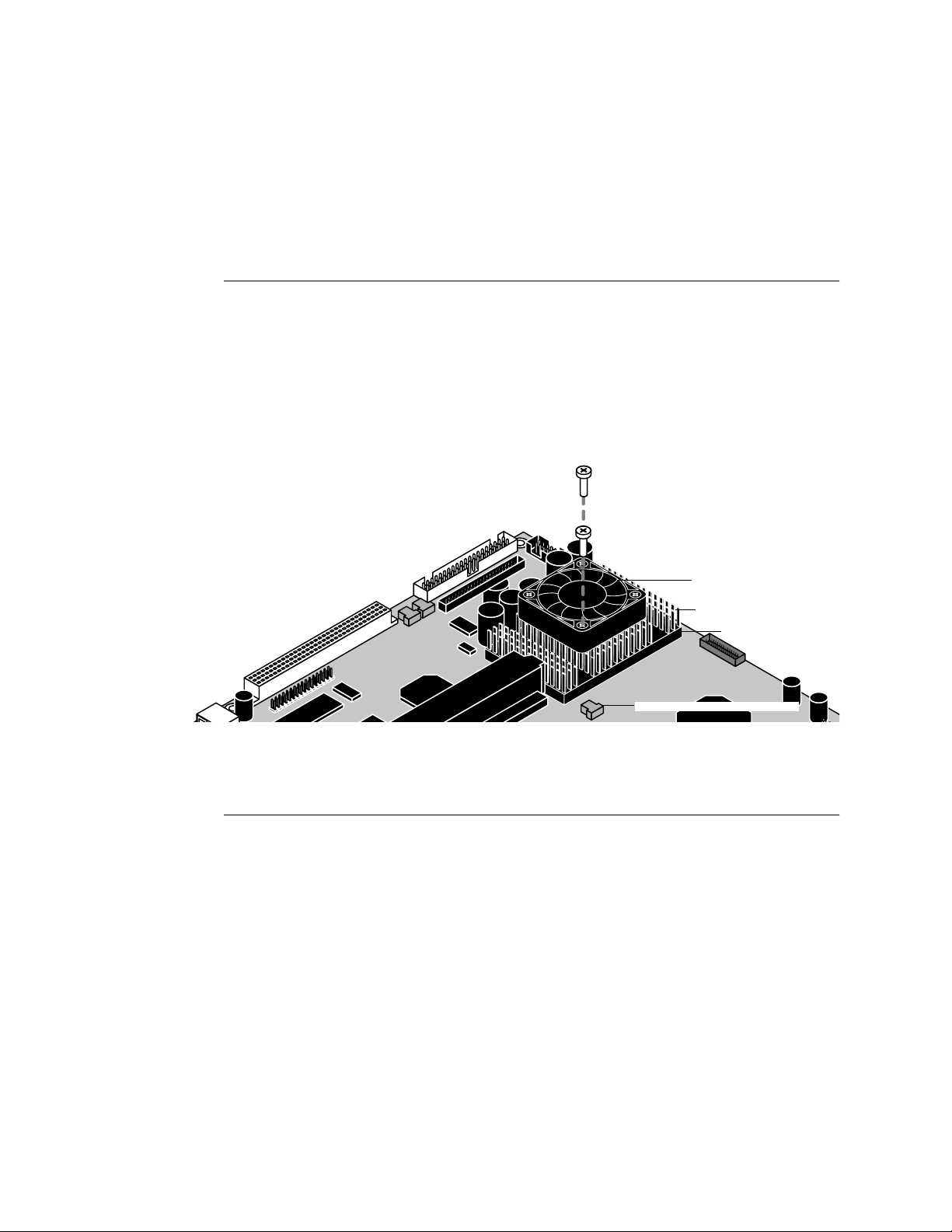
Replacing parts of the E-700
4
CPU fan
An air intake fan attached to the CPU heat sink runs continuously when the copier is on.
TO REMOVE THE CPU FAN
1. Shut down the copier and access the E-700 as described on page 4-3.
2. Remove the CPU fan cable from board connector J27.
3. Using a Phillips screwdriver, remove the two screws that fasten the CPU fan to the CPU
heatsink. Set aside the screws so that you can replace them later.
When using the screwdriver, make sure not to apply excessive pressure on the board.
FIGURE 4-12 Removing the CPU fan
4. Remove the CPU fan and set it aside.
TO INSTALL THE CPU FAN
1. Position the CPU fan on top of the CPU heatsink so that the arrow on the fan is pointing
to the copier interface board.
2. Attach the CPU fan to the CPU heatsink with the two screws you removed earlier.
When using the screwdriver, make sure not to apply excessive pressure on the board.
3. Connect the CPU fan cable to connector J27.
4. Reassemble the copier and verify functionality as described in “Restoring E-700
functionality after service” on page 4-22.
CPU fan
CPU heatsink
CPU
E-700 board
CPU fan cable connector (J27)
4-17
Page 52
Service Procedures
4
Exhaust fan
The exhaust fan is mounted on the side of the E-700 pan and pulls warm air out of the
E-700. Two arrows on the side of the fan indicate fan rotation and airflow direction. One
arrow should point away from the E-700 board. The exhaust fan cable connects to E-700
board connector J25.
TO REMOVE THE EXHAUST FAN
1. Shut down the copier and access the E-700 as described on page 4-3.
2. Remove the video interface board as described on page 4-12.
3. Remove the exhaust fan cable from E-700 board connector J25.
4. Remove the fan cable from the pan cutout.
Carefully cut any tie-wraps that join the fan cable to the power cable and to the standoff
for the E-700 board. Avoid cutting either cable.
5. Remove the four screws that secure the exhaust fan to the side of the E-700 pan.
Set aside the screws and fan.
TO REPLACE THE EXHAUST FAN
1. Align the exhaust fan with the four holes in the side of the pan.
Make sure that a direction arrow imprinted on the side of the fan is pointing away from
the E-700.
2. Insert the fan cable through the pan cutout.
3. Align the fan and replace the four screws through the fan into the side of the pan.
4. Replace the exhaust fan cable on E-700 board connector J25.
5. Drape the cable low and fully inside the pan to prevent the cable from being cut by the
pan cover when you reassemble the E-700.
Tie-wraps can be used to join the fan cable to the power cable and to the lower part of the
standoff for the E-700 board.
6. Replace the video interface board as described on page 4-13.
7. Reassemble the copier and verify functionality as described in “Restoring E-700
functionality after service” on page 4-22.
4-18
Page 53

Replacing parts of the E-700
4
Hard disk drive
The factory-installed hard disk drive (HDD) is formatted and loaded with all E-700
software, including operating software, system software, network drivers, and printer
fonts. Because the HDD is used to store spooled print jobs, available disk space is
displayed on the Info screen. Disk space is also listed on the Configuration Page (see
“Printing the Configuration page” on page 2-9).
If you are replacing the HDD, you will need:
• The appropriate System Software CD and documentation
• The latest version of user software (for networked computers that will be printing to
the E-700)
Proper handling
Handle the HDD with care:
• Use proper ESD practices when grounding yourself and the E-700.
• Keep magnets and magnetic-sensitive objects away from the HDD.
• Loosening the screws on the top of the HDD voids the warranty.
• Never drop, jar, or bump the HDD.
• Handle the HDD by its sides and avoid touching the printed circuit board.
• Allow the HDD to reach room temperature before installation.
Before you decide that the HDD needs to be replaced, make sure that all cables are
connected properly.
If the HDD needs to be replaced, you’ll need to install the system software on the new
HDD. Replacement drives are shipped without E-700 system software installed.
Make sure you attach an ESD grounding wrist strap and follow standard ESD
(electrostatic discharge) precautions before handling E-700 components.
4-19
Page 54
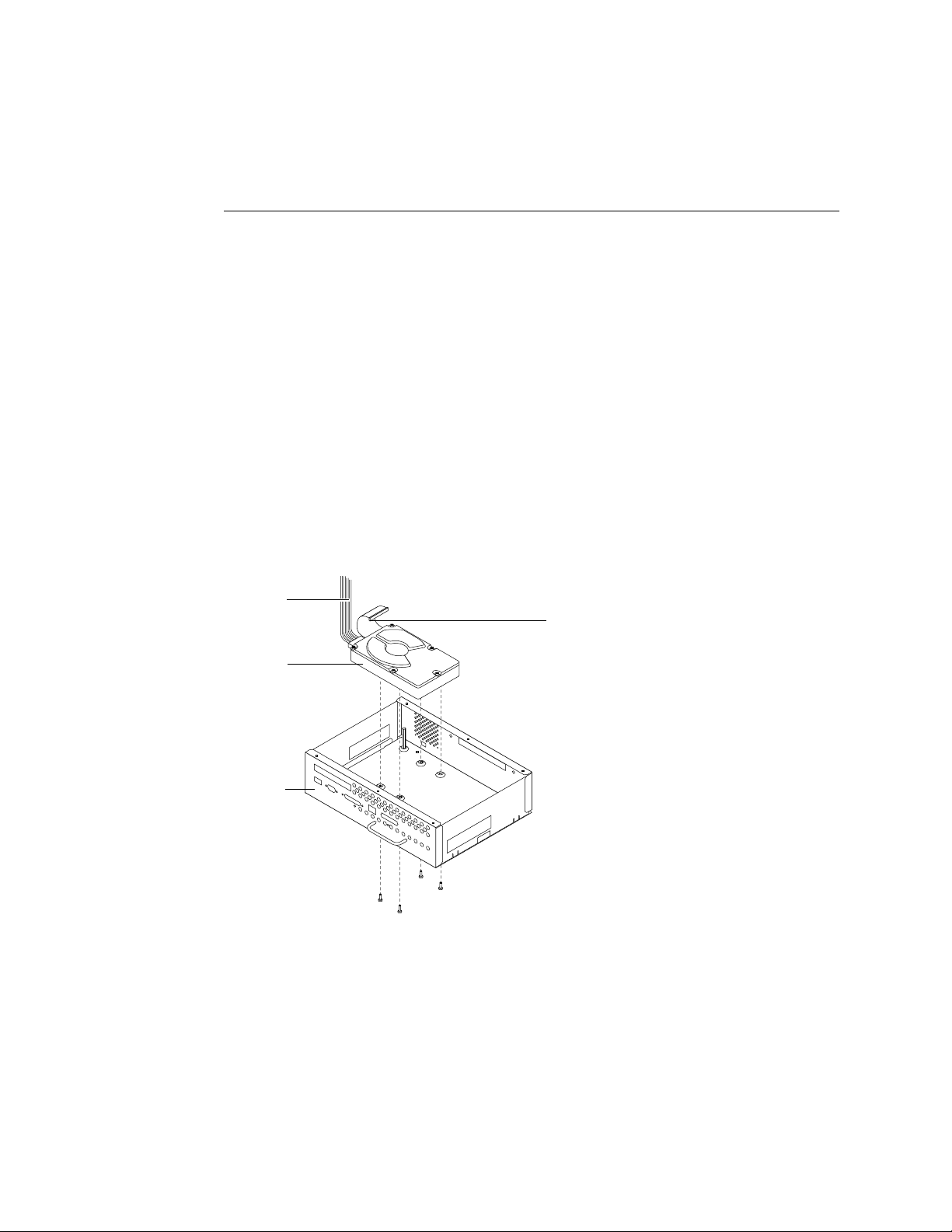
Service Procedures
4
TO REMOVE THE HDD
1. Print the following from the Functions menu:
• Configuration page —records the customer’s current Setup configuration.
If you are installing a new drive you will need to reinstall system software. The Setup
configuration will be reset to the default configuration when HDD is replaced.
• Font List— details the fonts that are resident on the E-700 HDD. The installed fonts
will need to be reinstalled when the HDD is replaced.
2. Shut down the copier and access the E-700 as described on page 4-3.
3. Remove the HDD cable from E-700 board connector J28.
4. Remove the E-700 board from the pan (see “To remove the E-700 board” on page 4-9).
5. With the pan on it side, remove the four screws on the bottom of the pan that secure the
HDD (see Figure 4-13).
Hold the HDD with one hand while you remove the screws.
Power cable
HDD
Pan
HDD cable
FIGURE 4-13 Replacing the HDD
6. Remove the power cable from the HDD.
7. Remove the HDD from the pan, remove the HDD cable from the HDD, and place the HDD
into an antistatic bag.
Do not touch the drive with magnetic objects, such as magnetic screwdrivers. Do not
place items near the hard disk drive that are sensitive to magnets, such as credit cards and
employee ID cards. See “Proper handling”.
4-20
Page 55

Replacing parts of the E-700
4
TO REPLACE THE HARD DISK DRIVE
Make sure you attach an ESD grounding wrist strap and follow standard ESD
(electrostatic discharge) precautions before handling E-700 components.
1. Remove the HDD from the antistatic bag, connect the HDD cable to the HDD, and insert
the HDD into the pan.
2. Connect the 4-wire connector of the power cable to the HDD.
The connector is keyed to fit only when properly oriented.
3. With the pan on its side, align the four holes in the bottom of the HDD with the holes in
the bottom of the pan and replace the four screws you removed earlier (see Figure 4-13
on page 4-20).
4. Replace the E-700 board (see “To replace the E-700 board” on page 4-10).
5. Replace the HDD cable to E-700 board connector J28.
6. Reassemble the copier and verify functionality as described in “Restoring E-700
functionality after service” on page 4-22 and other copier documentation.
Improper connection of the power cable can damage the E-700. See “Checking E-700
internal connections” on page 4-5 including Figure 4-5 on page 4-6.
7. If you replaced the HDD with a new drive, install system software (see page 4-24). If a
startup error occurs when you power on the copier, check E-700 connections. If a startup
error still occurs, call your authorized service/support center.
4-21
Page 56
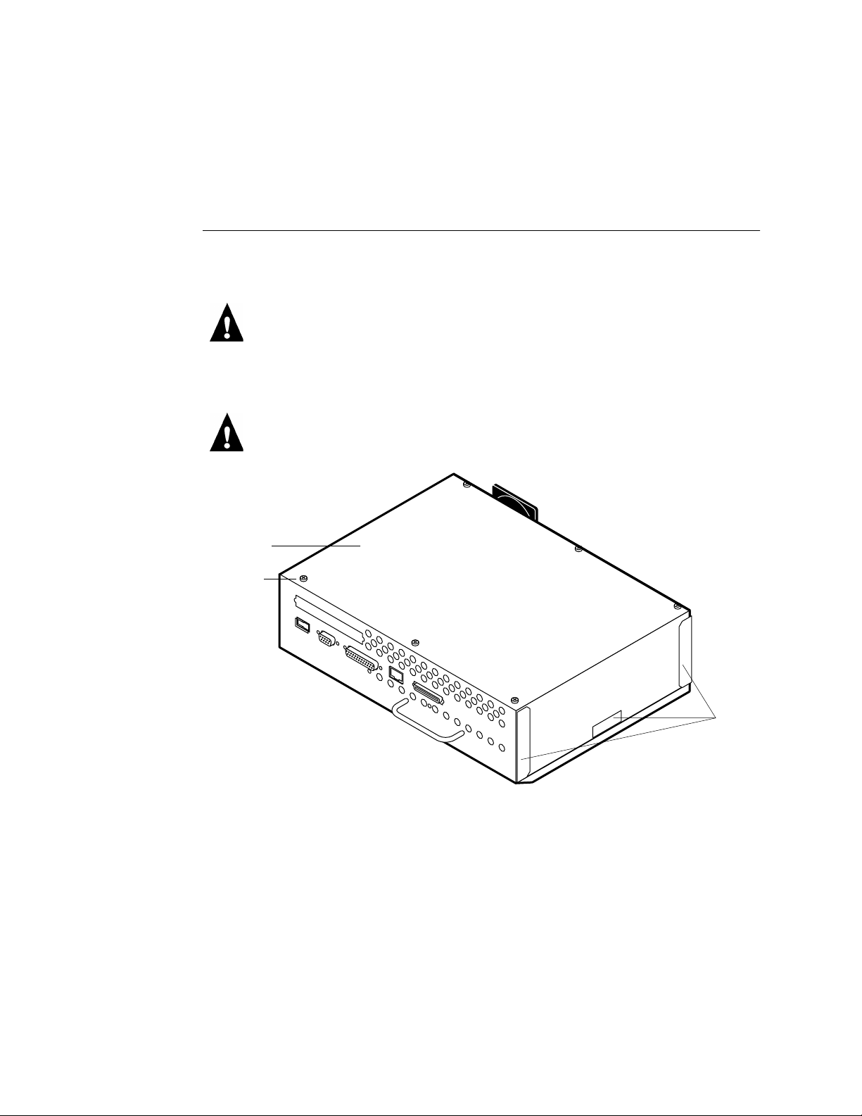
Service Procedures
4
Restoring E-700 functionality after service
TO RESTORE FUNCTIONALITY
1. Reinstall any boards, cables, connectors, and other parts of the E-700 that you loosened
during inspection or service.
Improper connection of the power cable can damage the E-700. See “Checking E-700
internal connections” on page 4-5 including Figure 4-5 on page 4-6.
2. Tighten the screws you loosened during inspection or service.
Make sure all components are in proper alignment as you tighten the screws.
3. Replace the pan cover on the pan, fitting the sides of the pan cover into the tabs.
Make sure all cables are low and fully inside the pan before you replace the pan cover.
Pan cover
Screw
FIGURE 4-14 Replacing the pan cover
4. Install the six screws you removed earlier.
5. Install the E-700 in the I/F unit and reassemble the copier (see “Installing the E-700 in
the copier” on page 2-5).
6. Connect any external cables that you removed during inspection or service.
Tabs
4-22
Page 57
Restoring E-700 functionality after service
4
7. Before you leave the customer site, verify E-700 operation (see Figure 4-15 on
page 4-23).
Power up and print a Test Page.
See page 2-8.
Connect the E-700 to the network.
See page 2-10.
Check the Setup options. See the
Configuration Guide.
F
IGURE 4-15 E-700 connection verification steps
4-23
Page 58

Service Procedures
4
E-700 system software
System is installed from a CD-ROM drive connected to the SCSI interface connector
(see page 4-25). The E-700 System Software CD includes the system software and fonts.
Use the System Software CD when:
• You replace the E-700 HDD
• You upgrade to a more recent version of the system software
The latest user software must be installed onto all computers that print to the E-700.
Using incompatible versions of the system and user software may result in system
problems.
System software installation reminders
Keep in mind the following when installing system software:
• Job Log—Formatting the HDD to install system software deletes the list of jobs in the
Job Log and any jobs in the queues. The network administrator can use Fiery Spooler
to save a current list of jobs (not the actual jobs) from the Job Log.
• Fonts—Formatting the HDD to install system software deletes all fonts installed on
the E-700 HDD. Resident fonts are restored during system software installation. If any
additional fonts were downloaded to the E-700, the network administrator can
reinstall the fonts using Fiery Downloader.
To determine which additional fonts were downloaded to the E-700, print the font list
before you install system software. Any fonts not listed after installation will need to be
reinstalled. See the Printing Guide for more information.
• Language—Screens for installing system software are always displayed in English even
if the E-700 is configured for another language.
• Compatibility—The latest user software should be installed onto all computers that
print to the E-700. Using incompatible versions of the system and user software may
result in system problems.
4-24
Page 59
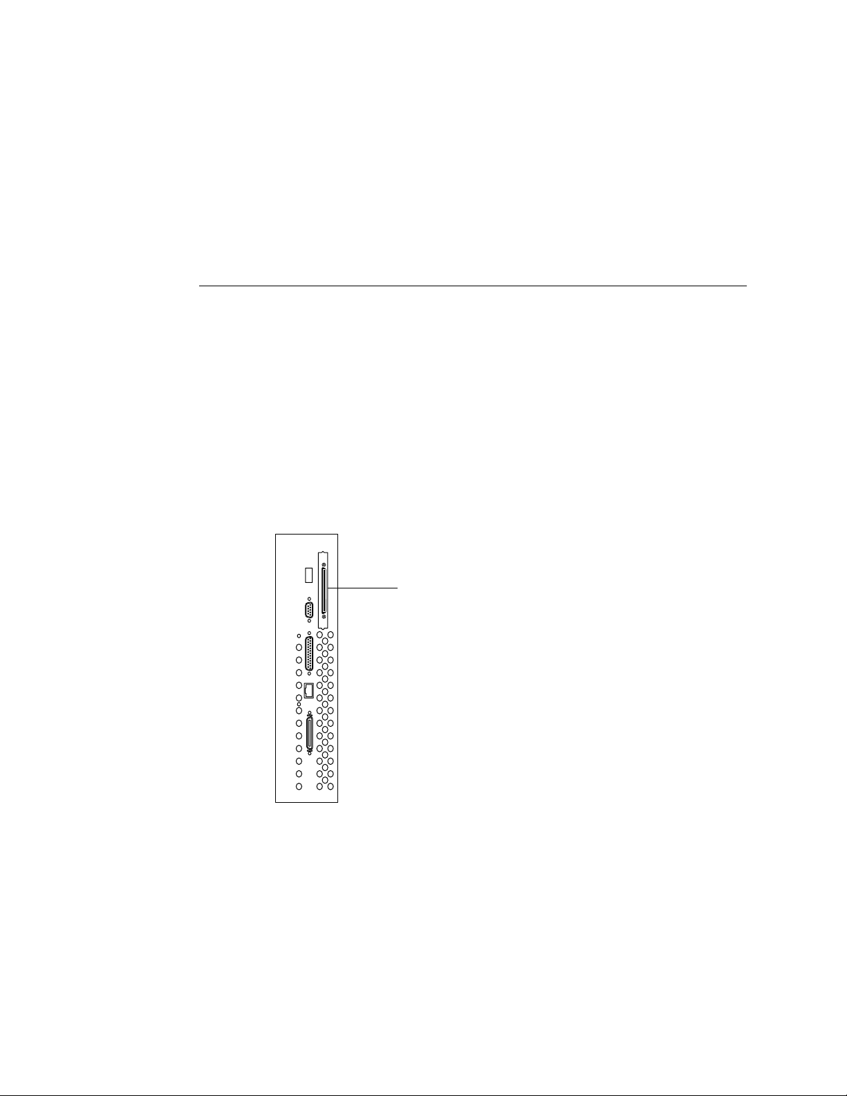
E-700 system software
4
Installing system software using the SCSI interface connector
To install system software, you will need an external CD-ROM drive and a SCSI cable to
connect the CD-ROM drive to the E-700 SCSI interface connector. Follow the
instructions below to attach the CD-ROM drive.
TO INSTALL SYSTEM SOFTWARE
1. Print the following from the E-700 Functions menu:
• Configuration page —records the customer’s current Setup configuration.
If you are installing a new drive you will need to reinstall system software. The Setup
configuration will be reset to the default configuration when system software is
installed.
• Font List— details the fonts that are resident on the E-700 HDD. The installed fonts
will need to be reinstalled when system software is installed.
2. Power off the E-700. Make sure that the CD-ROM drive is also powered off.
3. Attach the CD-ROM drive SCSI cable to the E-700 SCSI interface connector.
SCSI interface connector
F
IGURE 4-16 SCSI interface connector
4. Power on the CD-ROM drive and insert the System Software CD once the drive is free of
activity.
4-25
Page 60

Service Procedures
4
5. Power on the E-700; “Please Wait...” will flash on the Operation Panel as the E-700
boots from the System Software CD. System software installation will begin immediately.
Please wait . . .
6. Wait as the Operation Panel displays “Copying from CD”. The Operation Panel will also
show “Copied xxxxxK”, with xxxxx increasing as the installation proceeds.
N
OTE: System software installation will take approximately 35 minutes using a
2X CD-ROM drive.
Copied xxxxxK
7. When the installation file has completely copied from the CD, “Copying Complete, Please
Wait...” will appear.
Copying Complete
Please Wait . . .
8. The System Software CD will be ejected from the CD-ROM drive when “Remove CD” is
displayed.
Remove CD
9. After the System Software CD is ejected, “Installing System, Do Not Power Off” appears
on the Operation Panel. Do not press any keys or power the E-700 off when this screen is
displayed.
Installing system
Do not power off
10. When the language selection is then displayed on the LCD, select the desired language.
11. Once the desired language has been selected, the system will boot up using that
language.
12. After the system has started up completely, power it off and remove the attached
CD-ROM drive, then power the system back on.
13. The system is now ready for customer use.
4-26
Page 61

The troubleshooting process
5
Chapter 5:
Troubleshooting
Procedures
This chapter focuses on the troubleshooting process and identifies the source of common
problems that may occur with the Color Controller E-700 assembly and suggests ways of
correcting them.
The troubleshooting process
The troubleshooting process is designed to eliminate the most obvious causes of failure
before progressing to more complex issues. “Where problems occur” on page 5-2 gives an
overview of the E-700 components and indicates areas most likely to require
troubleshooting.
If the E-700 fails to complete its Start-up sequence and the E-700 does not reach the Idle
screen, the most likely cause is a loose cable or board connection. See “Checking E-700
internal connections” on page 4-5.
• Try a phone check before you go to the customer site.
“Before you go to the customer site” on page 5-3 suggests areas you should check out
before making a service call to the customer site. With a phone call, you can find out if
the problem is a simple operating failure or a failure caused by a network or
configuration change. You can ask the customer to check for loose cables on the side of
the copier and loose connections at a power strip or outlet.
• Check for obvious causes of problems.
“Preliminary on-site checkout” on page 5-4 takes you through the initial visual
checkouts you should make when you arrive at the customer site. You should check the
Operation Panel for an error message and see if the LEDs indicate an error condition.
Then inspect the copier externally and internally for the most common problems, such
as loose or faulty cables.
• Check network connections.
“Checking network connections” on page 5-9 provides guidelines for checking the
network connections between the copier and the computers to which it is connected as
well as information on several printing problems.
5-1
Page 62
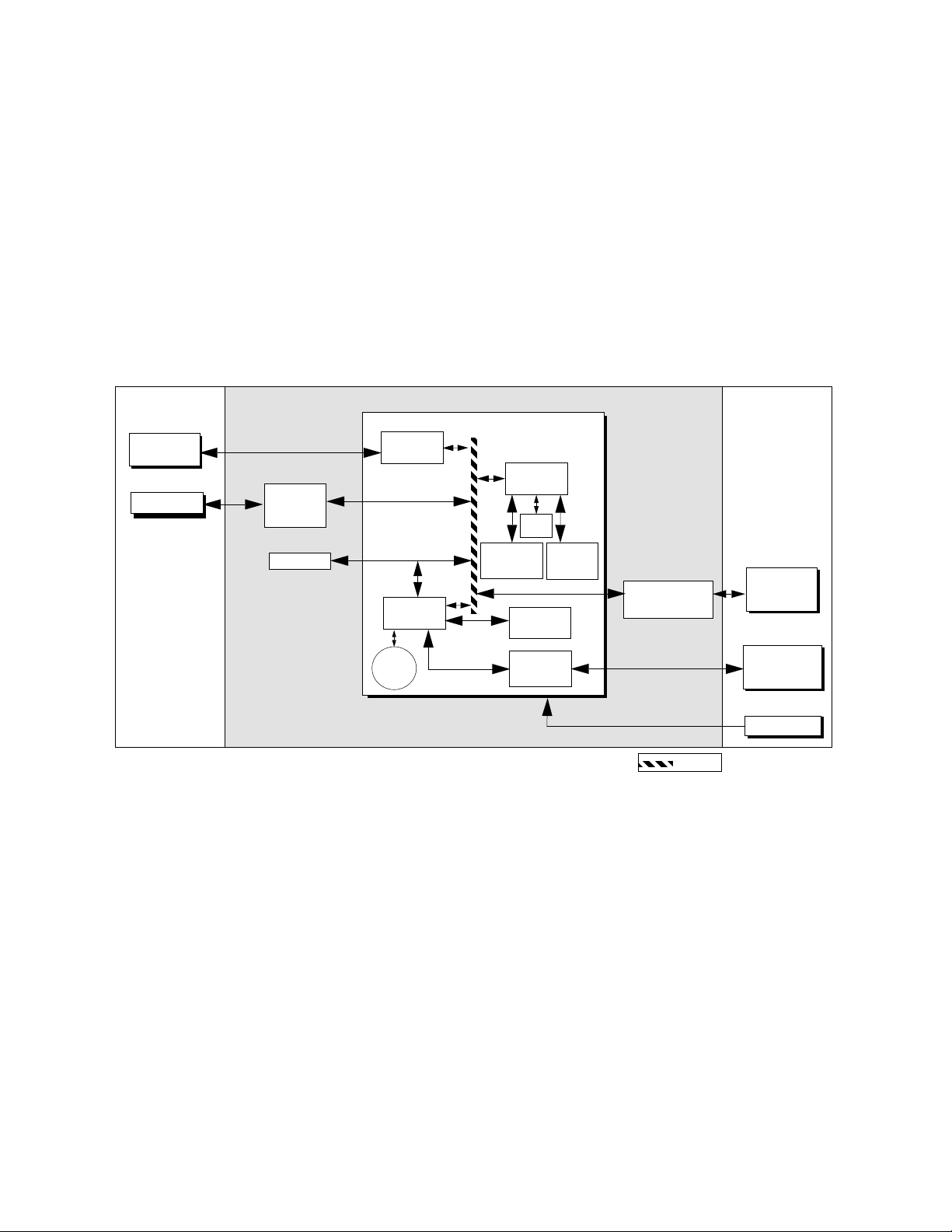
Troubleshooting Procedures
5
Where problems occur
The E-700 as a built-in print server for the copier is generally part of a configuration like
the one shown in Figure 5-1. Problems may occur in one of the following areas:
• The interface between the E-700 board and the copier
• The interface between the E-700 and computers on the same network
• The board or copier itself
External devices CopierE-700
E-700 Board
Networked
computers
SCSI Device
SCSI
interface
board
Network
interface
RIPChip
BIOS
HDD
RTC/
PCI-ISA
Battery
FIGURE 5-1 E-700 functional diagram
Memory &
Interpreter
Super I/O
controller
Operation
interface
Panel
+5VDC, +12VDC
CPU
Print/Scan
Video interface
board
PCI Bus
Copier
Operation
Panel
Display
Power supply
This chapter does not attempt to provide troubleshooting information for extensive
networks. You should refer problems in these areas to the appropriate service departments
and network administrators.
5-2
Page 63

Before you go to the customer site
5
Before you go to the customer site
Before you make a service call to a customer site, talk to the customer on the phone, and
check out the following items:
1. Does the copier work?
If the copier works, but the user cannot print the E-700 Test Page, have the customer
check the Message LED and any error messages in the Operation Panel. If the E-700
Operation Panel reports an error, check the copier interface cable between the E-700 and
the copier.
2. Is the failure caused by a simple operating problem?
• Is there a printing problem?
• Does the E-700 Test Page fail to print?
• Does the E-700 fail to respond to a print command?
• Does printing seem to take a long time?
• Is print quality poor?
• Does the E-700 fail to appear in the list of printers?
• Has the customer noted any error messages on the copier Operation Panel?
If the answer to any of these questions is yes, refer the customer to the Troubleshooting
Appendix in the Printing Guide.
If the customer has followed the corrective actions in the Printing Guide and has failed
to solve the problem, be prepared to make a service call. Keep a log of the failures and
messages the customer has observed.
3. Has the customer made any network changes?
If network changes have occurred, request that the customer’s network administrator
verify the E-700 network requirements.
4. Is the user having printing problems with a particular image file?
If there are problems with files from particular applications, the user may be more
successful using different print settings.
If your telephone call fails to clear up the problem, proceed to the next phase, the
preliminary on-site checkout.
5-3
Page 64
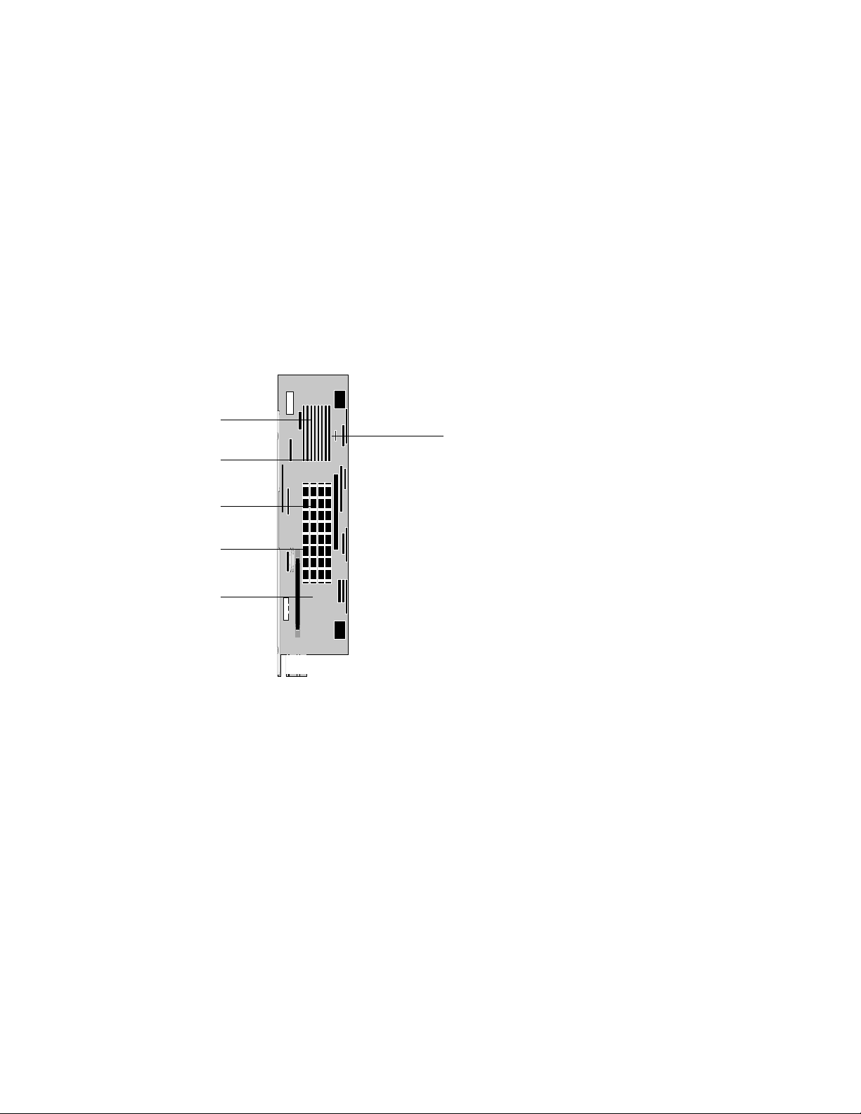
Not used
Not used
Troubleshooting Procedures
5
Preliminary on-site checkout
Your goal in the preliminary on-site checkout is to eliminate obvious problems, such as
loose or missing cables and connectors.
Checking connections
Before you remove the copier cover to inspect cables:
• Check that external interface cables are plugged into the proper connectors at the side
of the copier.
SCSI interface connector
Not used
10/100BaseT
Not used
FIGURE 5-2 External connectors
• Make sure the power cable is plugged into the wall outlet and that the copier is
powered on.
• Make sure the copier power supply cable is attached to the copier and to the E-700
board connector J20.
• Make sure the Operation Panel cable is attached to the copier and to the E-700 video
board.
Also, see “Checking E-700 internal connections” on page 4-5. See other documentation
for guidelines when disassembling, checking, and reassembling the copier. If all the
connectors are in place and the problem still exists when the copier is powered on, then
proceed to the next stage of troubleshooting.
5-4
Page 65

General E-700 system errors
5
General E-700 system errors
When you start up the system or when you install system software, you may encounter
error conditions that are not reported during the Start-up diagnostics. Table 5-1 lists
some of these error conditions and suggests corrective action.
When you first encounter any of these error conditions, power off the copier and inspect
for an obviously loose part or cable. Then check other components as suggested below.
For service procedures, refer to Chapter 4.
TABLE 5-1 General E-700 system error conditions and messages
Symptom Probable cause Suggested action
E-700 does not start up. Power cable is not properly
connected.
Power supply has failed. • Replace the copier power supply.
E-700 starts up but CPU fan is
not working or overheating.
CPU fan is working but does not
blow air away from the E-700.
Buttons do not work on the E-700
Operation Panel.
Nothing appears on the E-700
Operation Panel when the copier
is powered on
CPU fan is not properly
connected.
CPU fan is installed upside down. • Remove the CPU fan and reinstall it in the proper
Connection to the Operation
Panel is faulty or the Operation
Panel is bad.
Faulty chip on the E-700. • If the problem persists, you may have to replace the
Connections to the Operation
Panel are faulty or the Operation
Panel is faulty.
Faulty power supply. • Check power supply cable connections to the E-700
Bad DIMM connections • Open the E-700 to make sure that the DIMMs are
• Make sure that the power cable is connected between
the copier and the E-700 at J20 (see
internal connections” on page 4-5).
• Check CPU fan connection to E-700 connector J27
(see “CPU fan” on page 4-17).
• If problem persists, replace the CPU fan.
orientation (see “CPU fan” on page 4-17).
• Check cable connection to E-700 Operation Panel and
to the E-700 connector on the video interface board.
E-700 assembly.
• Check the cable connection to the copier and E-700
connector (see
connections” on page 4-5).
• Power on the copier and the E-700.
• If the problem persists, replace the cable.
• If the problem still persists, replace the E-700.
“Checking E-700 internal connections” on
(see
page 4-5).
• If problem persists, replace the copier power supply.
seated correctly.
• If the problem persists, try switching the DIMMs to
other slots.
• If problem still persists, replace DIMMs.
“Checking E-700 internal
“Checking E-700
5-5
Page 66

Troubleshooting Procedures
5
TABLE 5-1 General E-700 system error conditions and messages (Continued)
Symptom Probable cause Suggested action
Problem when installing system
software.
No CD is inserted or the wrong
CD is inserted in the CD-ROM
drive connected to the E-700.
Faulty System Software CD,
HDD, or CD-ROM drive.
• Check the CD inserted in the CD-ROM drive.
• Check HDD connections.
• If the problem persists, use a tested CD-ROM drive
cable.
• If the problem persists, try installing software using a
different System Software CD.
• If the problem still persists, you may need to replace the
HDD or us a different CD-ROM drive.
5-6
Page 67
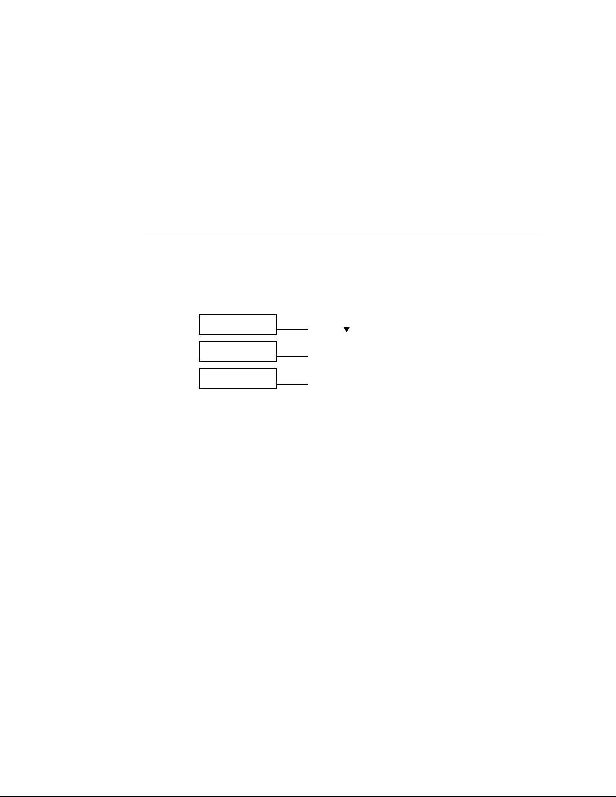
Video board diagnostics
5
Video board diagnostics
One of the menu items in the Functions screen on the E-700 Operation Panel is Run
Diagnostics. Select Run Diagnostics to run Video Diagnosticss if you suspect there may
be a problem with the E-700 video interface board (for example, the print quality of
output is poor) Video Diagnostics loops data internally, comparing data sent with data
received to make sure no errors have occurred.
TO RUN VIDEO DIAGNOSTICS
1. Power on the copier. Once the E-700 has reached the Ready screen, press the Menu key
to view the Functions menu.
2. Select Run diagnostics then Video Diagnostics. The test will start immediately.
Functions.
Print Pages
Functions.
Run Diagnostics
Press the key 3 times
Press the Set key to select
Diagnostics
Video Diags
3. If “Video Diags passed” appears, press the Cancel key to return to the Functions menu.
4. If “Video Diags failed” appears, then to fix the problem you may have to replace the
E-700 board.
Press the Set key to select
5-7
Page 68
Troubleshooting Procedures
5
Printing the Test Page
If the Test Page does not print at all or has a low-quality image, the E-700 board or the
copier interface cable may be faulty or the copier may not be functioning properly.
TO PRINT THE TEST PAGE
1. Power on the copier and allow it warm up.
Messages appear on the E-700 Operation Panel as the E-700 runs through its Start-up
diagnostics.
2. At the Ready screen, press the Menu key once to display the Functions menu.
3. Select Print Pages then Test Page.
Press the Set key to select the option displayed. Press the down arrow key to display each
option.
Functions
Print Pages
EXIT CUSTOM
Test Page
Press the Set key to select
The E-700 sends the Test Page to the copier and displays the RIP and Print status screens
so you can monitor the job.
4. Examine the quality of the Test Page from the copier.
If the Test Page prints successfully with good image quality, then the E-700 print engine
is functional and the connection between the E-700 and the copier is good.
5-8
Page 69

Checking network connections
5
Checking network connections
Printing problems may arise if the network hardware or software is not set up properly or
does not match network settings on the E-700. Problems may also arise when printing
from a specific application or printing a particular file.
Most of these problems show up as printing problems and do not necessarily indicate a
E-700 malfunction. The customer’s network administrator can eliminate many printing
problems without requiring you to make a service call. The network administrator deals
with:
• Print device error conditions
• Network connection problems that result in the copier not appearing in the list of
NOTE: If the copier does not appear in the list of printers on the network, there may be
another device on the network with the same Ethernet hardware address.
printers on the customer’s computers
• Conflicting network settings in Setup and on the customer’s computers
• Printing problems caused by inappropriate Setup options
• Application-specific printing errors caused by missing or incorrectly installed printer
description files
5-9
Page 70

Troubleshooting Procedures
5
Printing to the E-700
If the customer can print a E-700 Test Page but cannot print a job from a computer on
the network, you may have to make a service call. However, first make sure the network
administrator has done the following:
• Checked all components of the network including cables, connectors, terminators,
• Activated the network and used it to communicate with other printers.
• Checked the corrective actions listed in “E-700 Error Messages” in the Printing Guide.
• Confirmed that the applicable network settings in Setup (such as AppleTalk zone, IP
When you make a service call, check the E-700 faceplate at the side of the copier to make
sure that the appropriate network connection is in place.
network adapter boards, and network drivers.
address, Subnet mask, and Gateway address) match the settings used in the network.
Print quality problems are difficult to trace. Before you try to troubleshoot print quality
problems, print a Test Page to make sure that the copier does not need servicing or
adjusting. Also, make sure the correct paper is being used in the copier.
NOTE: EPS file generation is not completely standardized among applications. Some users
may encounter problems while printing certain EPS files.
5-10
Page 71

Checking network connections
5
General printing problems
If the copier is working properly, and the corrective actions listed in the Printing Guide
have not solved a printing problem, check the items listed in Table 5-2.
TABLE 5-2 Printing problems - General
Error Message or Condition Probable cause Suggested action
E-700 Test Page quality is
poor.
E-700 appears in the list of
printers on the customer’s
workstation, but certain jobs
do not print.
A print job stalls. A PostScript or application
Printing stops after one or a
few pages.
Color quality is uneven. A copier problem • Use the copier to copy a sample copier test page. If the quality is
Print quality is poor. A missing or outdated printer
Job never prints and the RIP
screen is active.
Copier and E-700 require
calibration.
A PostScript error
An application problem • Try printing a job from a different application to determine if
error
Faulty DIMM(s) • Reboot the copier and allow the Start-up diagnostics to run. If
A file or application problem • Print the E-700 Test Page.
description file
The application cannot find
the appropriate printer
description file.
The network cable was
plugged in when the copier
was already on.
• Perform copier calibration (see the Copier service
documentation for more information).
• Perform E-700 AutoCal (see the Color Guide for information).
• Make sure
Check for error messages on the E-700 output.
the problem is associated with a particular application.
• Cancel the E-700 print job.
• If this fails to clear the problem, reboot the E-700.
faulty DIMMs are detected, replace the faulty DIMMs.
• If this fails to clear the problem, try reinstalling the system
software.
not good, service the copier.
• If the quality of the E-700 Test Page is good, there may be a file
or an application problem.
• Make sure the appropriate printer description file is installed.
See Getting Started for a list of printer files used by various
applications.
• Turn off the copier and turn it back on again.
• Make sure Setup is configured correctly.
Print up to PostScript Error in Setup is set to Yes.
5-11
Page 72

Page 73

Hardware features
Appendix A:
Specifications
A
This chapter summarizes the hardware and networking features of the
Color Controller E-700.
Hardware features
• 366MHz Intel Celeron CPU
• 256MB memory
• SCSI interface connector for attaching a CD-ROM drive
• Adobe PostScript Level 3
• Battery—3V manganese dioxide lithium coin cell (Panasonic CR2032 or equivalent)
Networking and connectivity
The E-700 has the following networking features:
• Supports AppleTalk, TCP/IP, and IPX protocols simultaneously
• RJ-45 port for twisted pair (10BaseT/100BaseTX) network connection
User software
A complete description of E-700 user software is provided in Getting Started. For optimal
E-700 performance, current versions of the user software should be maintained on every
network computer that might print to the E-700.
Safety and emissions compliance
The E-700 board has been certified to meet or surpass the following standards:
Safety approvals EMI approvals
• UL, C-UL • FCC Class B
• EN 60950 (TÜV Bauart geprüft) • VCCI Class A
• EN 55022 Class B
• AS/NZS 3548 Class B
• EN 50082-1
• AS/NZS 42521
A-1
Page 74
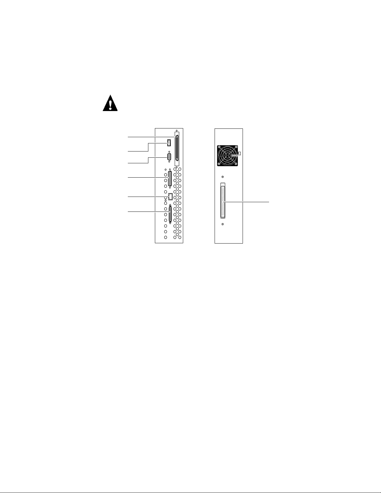
A
SCSI connector
Output voltage: +5V DC
USB connector (not used)
Output voltage: +5V DC
Serial connector (not used)
Output voltage: 0 V DC
Parallel connector (not used)
Output voltage: 0 V DC
10BaseT/100BaseT connector
Output voltage: 0 V DC
Parallel connector (not used)
Output voltage: 0 V DC
Specifications
Output voltage
On the E-700, the SCSI and USB connectors output +5V DC. The other external
connectors on the E-700 including the copier interface connector have no output voltage
(see Figure A-1).
Copier interface connector
Output voltage: 0 V DC
FIGURE A-1 E-700 output voltage
PTC Rating
R158, R135, R159
Rated hold current 0.75A
Rated trip current 1.5A
Max. voltage +15V DC
A-2
Page 75
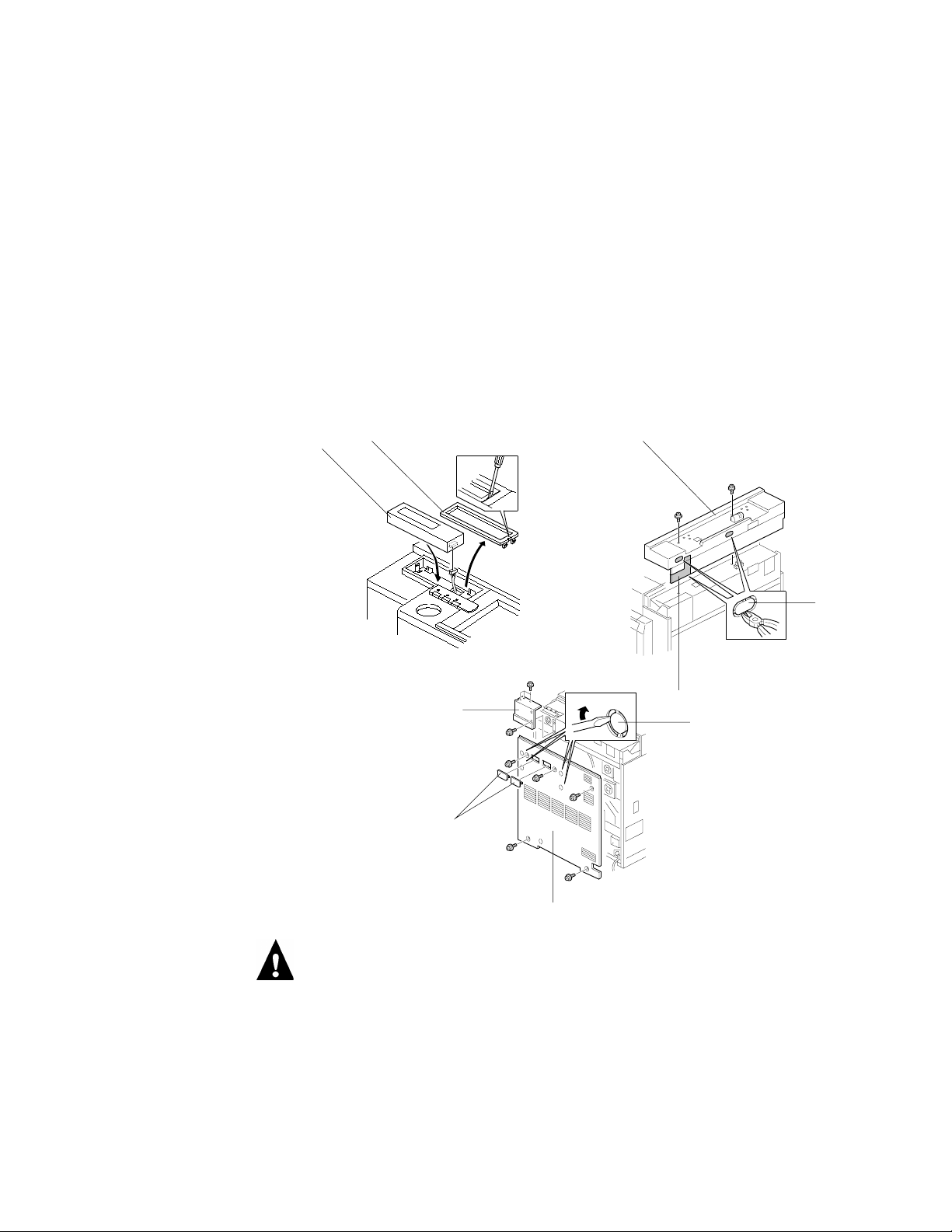
Installation Procedure
Appendix B:
Controller
Interface Type F
B
The Controller Interface Type F kit must be installed before installing the E-700.
This appendix provides the Controller Interface Type F Installation Procedure.
NOTE: In this procedure, the term “controller box” refers to the E-700 and the term
“interface unit” refers to the “I/F unit”. Also note that step 17 is covered in detail in
Chapter 2 “Installation.” In particular, see “Installing the E-700 in the copier” on
page 2-5.
Installation Procedure
[B]
[A]
A839I101.EPS
[I]
[F]
[C]
[D]
A839I501.EPS
[E]
[H]
A839I103.EPS
[G]
Unplug the copier power cord before starting the following procedure.
NOTE: Remove the platen cover or ADF if it is installed.
1. Remove the cover plate [A] from the Operation Panel with a small blade screwdriver.
Then, install the controller LCD panel [B] on the Operation Panel (1 connector).
2. Remove the upper rear cover [C] from the copier (2 screws) and cut out the 2 plastic
caps [D] and harness inlet plate [E] from the upper rear cover with cutting pliers.
B-1
Page 76
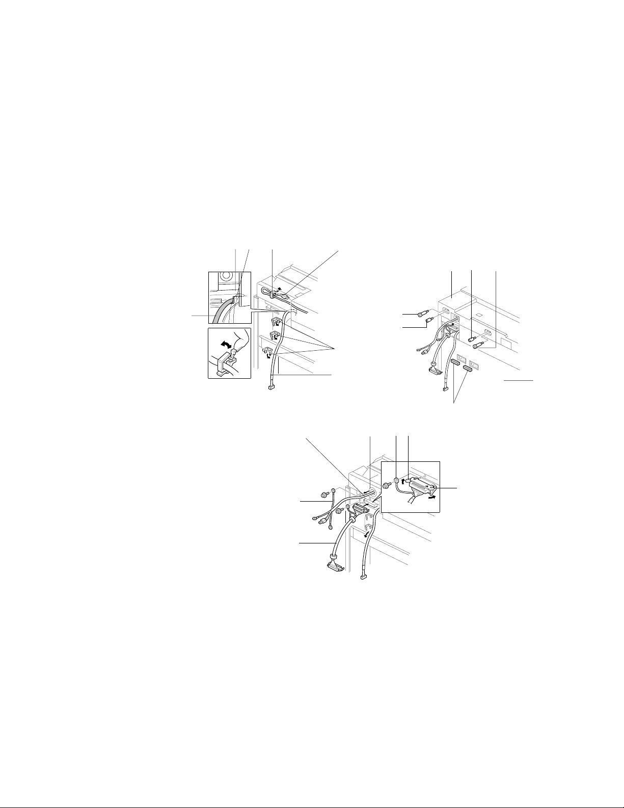
Controller Interface Type F
B
3. Remove the 2 plastic caps [F] from the rear cover [G]; then, remove the 4 metal caps [H]
with a blade screwdriver as shown.
N
OTE: Place a hand over the metal caps as you pry them out in order to control their
trajectory.
4. Remove the rear cover (5 screws) and shield cover [I] (4 screws).
(The shield cover will not be used any more.)
[A]
[E][F]
[C]
[B]
[G]
A839I104.EPS
[H]
[I]
[A]
[B]
[D]
[N]
[O]
[J]
[L]
[P]
[K][C]
[N][O]
[M]
A839I114.EPS
[K]
B-2
A839I113.EPS
5. Open 4 clamps [A] as shown, pull out the harnesses [B] & [C], and close the clamps.
Then, put the harness [C] through the harness bushing [D].
N
OTE: Make sure that the harness [B] is routed as shown. If it is routed in between the
bracket [E] and stay [F] as shown in dotted line, the harness may touch the flywheel [G].
6. Secure the grounding wire [H] (1 screw). (220 ~ 240 V version only)
Page 77
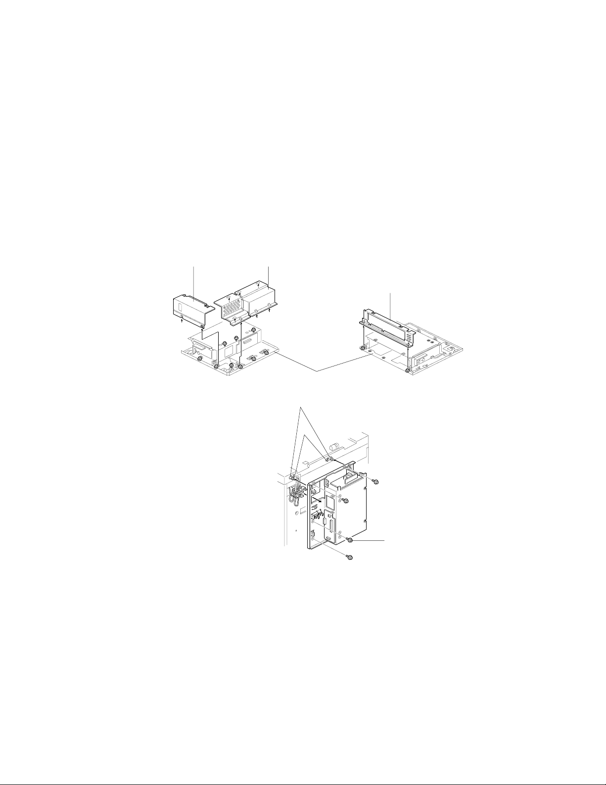
Installation Procedure
B
7. Connect the interface harness [I] (connector which has a grounding wire) to the LD
control board and secure the grounding wire [J] as shown (1 screw).
N
OTE: Insert the connector firmly so that the two lock hooks [K] are engaged as shown.
8. Reinstall the upper rear cover [L] and the rear cover [M] with the three harnesses (3
harnesses and grounding wire on 220 ~ 240 V version) outside the machine as shown.
9. Secure the hook stud screws [N] and stand-off stud screws [O] (2 each).
10. Peel off the seal of two-sided tape and attach the 2 conductive gaskets [P] as shown.
[A] [B]
[C]
A839I115.EPS A839I121.EPS
11. Loosen the screws securing the upper shielding cover [A], left shielding cover [B], and
right shielding cover [C]; then, remove them from the interface unit [D].
12. Put the 3 harnesses (3 harnesses and grounding wire on 220 ~ 240 V version) through
the cut-out of the interface unit and hook the interface unit on the stud screws [E].
Then, secure the 3 screws (2 screws go into the stand-off stud screws [F]) and 1
grounding screw [G].
[D]
[E]
[F]
[G]
A839I108.EPS
B-3
Page 78
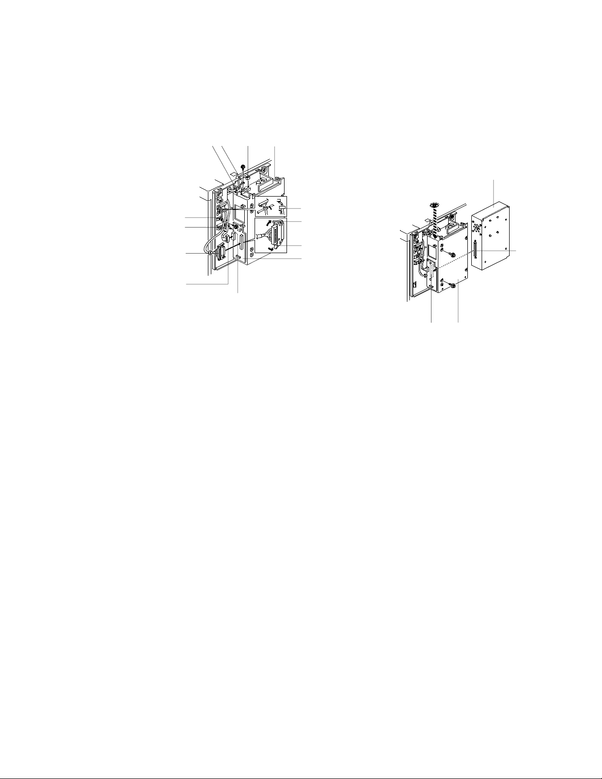
Controller Interface Type F
B
[E]
[A]
[J]
[I]
[F]
[H]
13. Secure the grounding wire [A] (1 screw). (220 ~ 240 V version only)
14. Secure the harness [B] in the clamp [C] and connect the 2P connector on the power
supply board [D] of the interface unit. Then, secure the grounding wire [E] as shown (1
screw).
[D][B][C]
[M]
[L]
[K]
[K]
[G]
A839I117.EPS
A839I518.EPS
[O] [N]
[O]
B-4
15. Connect the 24P connector [F] on the interface board [G] and secure the harness in the
clamp [H].
16. Connect the interface harness [I] to the interface board and secure the harness in the
clamp [J].
N
OTE: Insert the connector firmly so that the lock hooks [K] are engaged as shown.
Make sure that the ferrite core [L] is placed in the space of the cut out of the interface
unit as shown.
17. Insert the controller box [M] in the interface unit [N] (2 screws) (Look down through
the top of the interface unit to see the connectors. The controller box needs to be pulled
up slightly to engage the connectors smoothly.)
N
OTE: Make sure that the connectors [O] are firmly connected.
Page 79
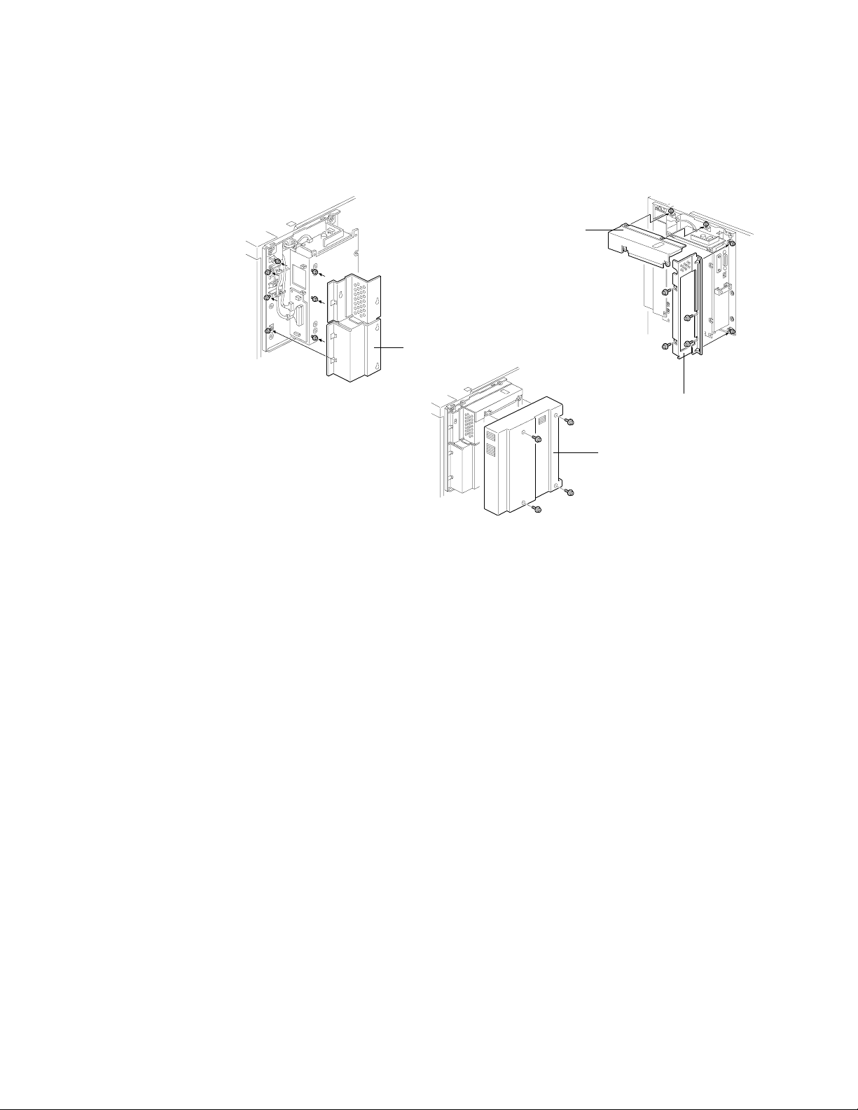
Installation Procedure
B
[C]
[A]
A839I119.EPS
A839I111.EPS
[D]
A839I120.EPS
18. Reinstall the left shield cover [A] (7 screws).
19. Reinstall the right shield cover [B] (6 screws) and upper shield cover [C] (2 screws).
20. Install the interface unit cover [D] (4 screws).
21. See the Configuration Guide for Setup information.
[B]
B-5
Page 80

Page 81

Index
Numerics
10/100BaseT 2-10
A
activity indicators
error 3-2
printer/scanner 3-2
printing/processing 3-2
AppleTalk 1-1
B
banks, DIMM 4-15
battery 4-16, A-1
BIOS 4-25
C
cables
checking 5-4
connections 4-5
HDD 4-21
reseating 4-5
cancel key 3-2
CD
System Software 4-19, 4-24
User Software 1-3
checking
cables 4-5, 5-4
network connections 5-9
chips
CPU 1-2
Rip 1-2
Color Separation and Gray Scale 2-2
Configuration page 2-9, 3-4
connecting
to the network 2-10
connectors
copier interface 2-5
network 2-10
SCSI A-2
twisted pair (10/100BaseT) 2-10
USB A-2
Controller Interface Type F kit xi, 2-2
copier interface connector 2-5
CPU 1-2
CPU fan 4-17
– 2-6, 4-5
– 2-6, 4-5
D
damage, reporting xiii
DIMMs
banks 4-15
configurations 1-2, 4-15
removal and replacement 4-15
disk space 4-25
down arrow key 3-2
E
ECP mode 4-25
EMI approvals A-1
enter key 3-2
EPS files, printing 1-3
error light 3-2
errors
installing system software 5-5
system 5-5
ESD (electrostatic discharge) safety
precautions xiii
Ethernet address 5-9
exhaust fan 4-18
F
fan
CPU 4-17
fans
exhaust 4-18
Fiery Downloader 1-3
Fiery WebTools 1-4
Font List option 3-4
Functions menu
Configuration page 3-4
Font List 3-4
Help Map 3-4
Job Log 3-4
Print Pages 3-4
Reboot Server 3-4
Resume Printing 3-4
Suspend Printing 3-4
Test Page 3-4
G
Gray Scale 2-2
I-1
Page 82

Index
H
hard disk drive
proper handling 4-19
removal 4-19, 4-21
system software 4-19
hardware specifications A-1
Help Map 3-4
I
Install Software 3-5
IP address xiii
IPX (Novell) 1-1
J
Job Log
option in Functions menu 3-4
printing 3-4
K
keys
cancel 3-2
down arrow 3-2
enter 3-2
left arrow 3-2
menu 3-2
printer/scanner 3-2
right arrow 3-2
up arrow 3-2
L
LAN (local area network) xiii
LEDs
error 3-2
printer/scanner 3-2
printing/processing 3-2
left arrow key 3-2
M
Media package 2-2
menu
Start up 3-5
menu key 3-2
Menu Map 3-4
N
network connections
checking 5-9
twisted pair (10/100BaseT) 2-10
networks
connecting to 2-10
Novell (IPX) 1-1
supported 1-1, A-1
Novell (IPX) networks 1-1
O
on-board
battery 4-16
DIMMs 4-15
Operation Panel
definition xii
touch panel display 3-3
troubleshooting 5-5
P
PostScript files, printing 1-3
precautions xiii
printer mode 3-3
printer/scanner
activity indicator 3-2
key 3-2
Print Font List option 3-4
Print Help Map option 3-4
printing
Configuration page 3-4
Font List 3-4
Help Map 3-4
Job Log 3-4
pages 3-4
problems 5-10
test page, copier 2-3
Test Page, server 2-8, 3-4
printing/processing light 3-2
Print Pages option 3-4
I-2
Page 83

Index
R
Reboot Server option 3-4
Reboot System 3-5
reseating connections 4-5
Resume Printing option 3-4
right arrow key 3-2
RipChips 1-2
RIP-While-Print 1-3
Run Diagnostics option 3-4
Run Setup 3-5
S
safety approvals A-1
screens 2-8
Start up 3-5
select, using the enter key 3-2
service calls
tools required xiv
Setup, accessing 3-3
software, user 2-1
specifications, hardware A-1
Start System 3-5
Start up menu 3-5
Suspend Printing option 3-4
system errors 5-5
system software installation reminders 4-24
– 2-2
T
TCP/IP 1-1
test page, copier 2-3
Test Page, server 2-8, 3-4
tools required for service xiv
troubleshooting
Operation Panel 5-5
twisted pair (10/100BaseT) 2-10
U
up arrow key 3-2
user software 2-1
User Software CD 1-3
User Software contents 1-3
– 2-2
V
voltage A-2
W
WebTools 1-4
I-3
Page 84

 Loading...