

Ricoh FAX2700L SPECIFICATIONS fx4700

FX4
RICOH FAX4700L
SERVICE MANUAL
December 21st, 1995
Subject to change

WARNING
I
THIS MACHINE CONTAINS A LASER BEAM GENE RATOR. LASER
BEAMS CAN CAUSE PERMANENT EYE DAMAGE. DO NOT OPEN THE
LASER UNIT OR LOOK ALONG THE LASER BEAM PATH WHILE THE
MAIN POWER IS ON.
Lithium Batteries (Memory Back-up)
CAUTION
I
The danger of explosion exists if a battery of this type is incorr ectly
replaced. Replace only with the same or an equival ent type
recommended by the manufac ture r. Discard used batteries in
accordance with the manufacturer’s instructions.

Table of Contents
1. OVERALL MACHINE INFORMATION
1.1. SPECIFICATIONS . . . . . . . . . . . . . . . . . . 1-1
1.2. FEATURES . . . . . . . . . . . . . . . . . . . . . 1-2
1.2.1. Featu res List . . . . . . . . . . . . . . . . . . . 1-2
1.2.2. Capabilitie s of Pro grammable Items . . . . . . . . . . 1-6
1.2.3. Possible Combin ations of Optional Equipment . . . . . . 1-7
1.3. COMPONENT LAYOUT . . . . . . . . . . . . . . . . 1-8
1.3.1. Mechanical Comp on en ts . . . . . . . . . . . . . . 1-8
1.3.2. Electrical Co mpo ne nt s . . . . . . . . . . . . . . . 1-10
1. PCBs . . . . . . . . . . . . . . . . . . . . . . 1-11
2. Motors . . . . . . . . . . . . . . . . . . . . . . 1-11
3. Sensors . . . . . . . . . . . . . . . . . . . . . 1-12
4. Interlock Switches . . . . . . . . . . . . . . . . . 1-12
5. Others . . . . . . . . . . . . . . . . . . . . . . 1-12
6. Optional Equ ipme nt . . . . . . . . . . . . . . . . 1-13
1.4. OVERALL MACHINE CONTROL . . . . . . . . . . . . 1-14
1.5. VIDEO DATA PATH . . . . . . . . . . . . . . . . . . 1-16
1.5.1. Transmission (PSTN) . . . . . . . . . . . . . . . 1-16
1.5.2. Reception (P STN) . . . . . . . . . . . . . . . . . 1-17
1.5.3. Transmission (ISDN) . . . . . . . . . . . . . . . . 1-18
1.5.4. Reception (I SDN) . . . . . . . . . . . . . . . . . 1-19
1.5.5. Copying . . . . . . . . . . . . . . . . . . . . . 1-20
1.5.6. Printing from the Optional Printe r Int erf ace . . . . . . . 1-21
1.6. POWER DISTRIBUTION . . . . . . . . . . . . . . . . 1-22
1.6.1. Distribution Dia gra m . . . . . . . . . . . . . . . . 1-22
1.6.2. Memory Back-up Circuit . . . . . . . . . . . . . . 1-24
1. SRAM/Real Time Clock (RTC) Backup . . . . . . . . . 1-24
2. DRAM Backup . . . . . . . . . . . . . . . . . . 1-25
2. DETAILED SECTION DESCRIPTIONS
2.1. SCANNER . . . . . . . . . . . . . . . . . . . . . 2-1
2.1.1. Mechanisms . . . . . . . . . . . . . . . . . . . 2-1
1. Document Detection . . . . . . . . . . . . . . . . 2-1
2. Pick-up and Separation . . . . . . . . . . . . . . . 2-2
3. Drive Mechanism . . . . . . . . . . . . . . . . . 2-3
4. Stamping . . . . . . . . . . . . . . . . . . . . . 2-5
2.1.2. Image Scanning * . . . . . . . . . . . . . . . . . 2-6
1. Sub Scan Resolution Conversion . . . . . . . . . . . 2-6
2. Partial Image Scann ing * . . . . . . . . . . . . . . 2-7
3. Scanning Double-sid ed Documents * . . . . . . . . . . 2-8

2.1.3. Vi d eo Proce ssing * . . . . . . . . . . . . . . . . 2-10
2.1.4. Shading Correction and A /D Con versio n * . . . . . . . 2-11
2.1.5. Process withou t Half tone * . . . . . . . . . . . . . 2-11
1. Background Det ect ion . . . . . . . . . . . . . . . . 2-11
2. MTF . . . . . . . . . . . . . . . . . . . . . . . 2-11
3. Thresho ldin g . . . . . . . . . . . . . . . . . . . 2-11
4. Erasure of irregula r dot s . . . . . . . . . . . . . . . 2-11
5. OR processing . . . . . . . . . . . . . . . . . . 2-12
2.1.6. Process with Halftone * . . . . . . . . . . . . . . . 2-12
1. Gamma correction . . . . . . . . . . . . . . . . . 2-12
2. MTF . . . . . . . . . . . . . . . . . . . . . . . 2-12
3. Halftone proce ss . . . . . . . . . . . . . . . . . . 2-12
2.1.7. Data Swit ching * . . . . . . . . . . . . . . . . . 2-12
2.1.8. Inch-mm Conversio n . . . . . . . . . . . . . . . . 2-13
2.2. PRINTING . . . . . . . . . . . . . . . . . . . . . . 2-14
2.2.1. Printing Process - Overview . . . . . . . . . . . . . 2-14
2.2.2. OPC Drum . . . . . . . . . . . . . . . . . . . . 2-15
2.2.3. Charge * . . . . . . . . . . . . . . . . . . . . 2-15
2.2.4. Laser Exp osu re . . . . . . . . . . . . . . . . . . 2-17
1. Overview * . . . . . . . . . . . . . . . . . . . . 2-17
2. Block Diagram . . . . . . . . . . . . . . . . . . . 2-18
3. Error Conditions * . . . . . . . . . . . . . . . . . 2-18
4. Print Den sity Adjustment . . . . . . . . . . . . . . . 2-19
5. Toner Saving Mod e . . . . . . . . . . . . . . . . . 2-19
2.2.5. Toner Supply . . . . . . . . . . . . . . . . . . . 2-20
2.2.6. Develop ment . . . . . . . . . . . . . . . . . . . 2-23
2.2.7. Paper Feed . . . . . . . . . . . . . . . . . . . 2-28
1. Overview * . . . . . . . . . . . . . . . . . . . . 2-28
2. Paper Lift Mechanism . . . . . . . . . . . . . . . . 2-29
3. Paper Size and Paper End Detection . . . . . . . . . . 2-30
4. Pick-up and Separation . . . . . . . . . . . . . . . 2-32
5. Drive Mechanism * . . . . . . . . . . . . . . . . . 2-32
2.2.8. Registra tion * . . . . . . . . . . . . . . . . . . . 2-35
2.2.9. Transfer and Separation . . . . . . . . . . . . . . 2-37
2.2.10. Cleaning . . . . . . . . . . . . . . . . . . . . 2-40
2.2.11. Fusing . . . . . . . . . . . . . . . . . . . . . 2-41
2.2.12. Page Sepa rat ion and Data Redu ction . . . . . . . . 2-45
2.2.13. Resolution Unit Selection for Print ing * . . . . . . . . 2-47
2.2.14. Paper Size Selection * . . . . . . . . . . . . . . 2-47
2.3. SYSTEM FEATURES . . . . . . . . . . . . . . . . . 2-48
2.3.1. Energy Saver Modes * . . . . . . . . . . . . . . . 2-48
1. Going into a Energy Sa ver Mod e . . . . . . . . . . . 2-49
2. Going into Level 2 Mode from Le vel 1 Mod e * . . . . . . 2-51
3. Receiving a Fax Message in En erg y Saver Mode . . . . . 2-53
4. Sending a Fax Message or Copying in Energy Saver Mode . 2-55

2.3.2. Au to mat ic S ervice Calls . . . . . . . . . . . . . . 2-57
1. Service Call Condition s . . . . . . . . . . . . . . . 2-57
2. Excessive Jam A larms * . . . . . . . . . . . . . . . 2-58
3. Periodic Service Call * . . . . . . . . . . . . . . . 2-59
4. PM Call * . . . . . . . . . . . . . . . . . . . . . 2-60
5. Effective Term o f S ervice Calls * . . . . . . . . . . . . 2-60
2.3.3. Parallel Memory Transmission * . . . . . . . . . . . 2-61
2.3.4. Transfer Broadcasting * . . . . . . . . . . . . . . . 2-63
2.3.5. Fax On Deman d * . . . . . . . . . . . . . . . . . 2-66
2.3.6. Hard Disk Filing System * . . . . . . . . . . . . . . 2-68
2.4. PCBs . . . . . . . . . . . . . . . . . . . . . . . 2-69
2.4.1. MFCE * . . . . . . . . . . . . . . . . . . . . . 2-69
2.4.2. MFDU . . . . . . . . . . . . . . . . . . . . . 2-72
2.4.3. PSU . . . . . . . . . . . . . . . . . . . . . . 2-74
2.4.4. NCU (USA) . . . . . . . . . . . . . . . . . . . 2-74
2.4.5. NCU (Europe/A sia) . . . . . . . . . . . . . . . . 2-75
3. INSTALLATION *
3.1. INSTALLING THE MACHINE . . . . . . . . . . . . . . 3-1
3.2. INITIAL PRO GRAMMI NG * . . . . . . . . . . . . . . . 3-1
3.3. INSTALLING OPTIONAL UNITS . . . . . . . . . . . . . 3-2
3.3.1. Feature Expan de r Type 140 (80MB Hard Disk) * . . . . . 3-2
3.3.2. ISDN G4 Interface * . . . . . . . . . . . . . . . . 3-4
3.3.3. Fax on Deman d * . . . . . . . . . . . . . . . . . 3-6
3.3.4. Counter * . . . . . . . . . . . . . . . . . . . . 3-7
3.3.5. Printe r I nt erf ace * . . . . . . . . . . . . . . . . . 3-8
3.3.6. Important Not ice fo r t he Funct ion Upgrade Card and
Fax On Demand Card * . . . . . . . . . . . . . . . 3-10
4. SERVICE TABLES AND PROCEDURES
4.1. SERVICE LEVEL FUNCTIONS * . . . . . . . . . . . . . 4-1
4.1.1. Bit Switch Programmin g (Fun ctio n 01 ) . . . . . . . . . 4-1
4.1.2. Group 3 Syste m Para meter List (Function 02) . . . . . . 4-2
4.1.3. Error Code Display (Function 03) . . . . . . . . . . . 4-4
4.1.4. Service Monitor Repo rt (Fun ctio n 04 ) . . . . . . . . . 4-4
4.1.5. Group 3 Prot oco l Dump (Function 05) . . . . . . . . . 4-4
4.1.6. RAM Display/Rewrite (Funct ion 06) . . . . . . . . . . 4-5
4.1.7. RAM Dump (Funct ion 06) . . . . . . . . . . . . . . 4-5
4.1.8. Counter Displa y/Rewrite (Function 07) . . . . . . . . . 4-6
4.1.9. Modem Test (Function 08) . . . . . . . . . . . . . . 4-7
4.1.10. DTMF Tone Test (Fu nct ion 08) . . . . . . . . . . . 4-7
4.1.11. NCU Parameters (Function 08) . . . . . . . . . . . 4-8
4.1.12. Modem Detection Test (Function 08) . . . . . . . . . 4-8

4.1.13. Ringer Test (Function 08) . . . . . . . . . . . . . 4-9
4.1.14. Ope rat ion Panel Test (Function 09) . . . . . . . . . 4-10
4.1.15. Xenon La mp Test (Function 10) . . . . . . . . . . . 4-10
4.1.16. ADF Test (Function 10) . . . . . . . . . . . . . . 4-11
4.1.17. Printer Test Patterns (Fun ctio n 11) . . . . . . . . . . 4-11
4.1.18. Scanner and Printer Mechanism Test - Free Run
(Function 11) . . . . . . . . . . . . . . . . . . 4-12
4.1.19. RAM Tests (Function 12) . . . . . . . . . . . . . . 4-12
4.1.20. Softwa re Down load (Function 12) . . . . . . . . . . 4-13
4.1.21. Softwa re Uplo ad (Function 12) . . . . . . . . . . . 4-15
4.1.22. SRAM Data Down loa d (Fun ction 12) . . . . . . . . . 4-17
4.1.23. Saving Dat a Programmed in IC Cards . . . . . . . . 4-18
1. When downloading /uploading software . . . . . . . . . 4-18
2. When replacing the MFCE . . . . . . . . . . . . . . 4-19
3. When replacing th e MFDU or o th er comp on ents . . . . . 4-20
4.1.24. Service Sta tio n Fax Numb er (Function 13) . . . . . . . 4-20
4.1.25. Serial Numbe r (Fu nct ion 14) . . . . . . . . . . . . 4-21
4.1.26. Hard Disk Initializa tio n (Fun ctio n 16) . . . . . . . . . 4-21
4.1.27. Hard Disk Formattin g (Fun ctio n 16) . . . . . . . . . 4-22
4.1.28. Hard Disk Test (Function 16) . . . . . . . . . . . . 4-22
4.1.29. G4 Parameter Programming (Function 17) . . . . . . . 4-23
4.1.30. Printing Conf idential Files . . . . . . . . . . . . . 4-23
4.2. BIT SWITCHES . . . . . . . . . . . . . . . . . . . 4-24
4.2.1. System Switches . . . . . . . . . . . . . . . . . 4-24
4.2.2. Scanner Swit che s . . . . . . . . . . . . . . . . 4-36
4.2.3. Printer Switches . . . . . . . . . . . . . . . . . 4-38
4.2.4. Communication Switches . . . . . . . . . . . . . . 4-41
4.2.5. G3 Switches . . . . . . . . . . . . . . . . . . . 4-49
4.3. NCU PARAMETERS . . . . . . . . . . . . . . . . . 4-56
4.4. DEDICATED TRANSMISSION PARAMETERS . . . . . . . 4-81
4.4.1. Programming Procedure . . . . . . . . . . . . . . 4-81
4.4.2. Parame te rs . . . . . . . . . . . . . . . . . . . 4-82
4.5. SERVICE RAM ADDRE SSES . . . . . . . . . . . . . . 4-85
4.6. SPECIAL TOOLS AND LUBRICANTS . . . . . . . . . . 4-101
4.7. PM TABLE . . . . . . . . . . . . . . . . . . . . . 4-102
5. REPLACEMENT AND ADJUSTMENT
5.1. COVERS . . . . . . . . . . . . . . . . . . . . . . 5-1
5.1.1. Docu men t Table and Tray . . . . . . . . . . . . . . 5-1
5.1.2. Rea r Co ver Assembly . . . . . . . . . . . . . . . 5-2
5.1.3. Left Cover . . . . . . . . . . . . . . . . . . . . 5-2
5.1.4. Right Cove r . . . . . . . . . . . . . . . . . . . 5-3
5.1.5. Op era tion Panel A ssemb ly . . . . . . . . . . . . . 5-3
5.1.6. Top Cover . . . . . . . . . . . . . . . . . . . . 5-4

5.2. ADF . . . . . . . . . . . . . . . . . . . . . . . . 5-5
5.2.1. ADF Roller Assembly . . . . . . . . . . . . . . . . 5-5
5.2.2. Separation Rubber Plate . . . . . . . . . . . . . . 5-5
5.2.3. Se paration Pressure Ad justment . . . . . . . . . . . 5-6
5.2.4. ADF Sensors . . . . . . . . . . . . . . . . . . . 5-6
5.3. SCANNER . . . . . . . . . . . . . . . . . . . . . 5-8
5.3.1. Exposure Glass . . . . . . . . . . . . . . . . . . 5-8
5.3.2. R1/R2 Rollers . . . . . . . . . . . . . . . . . . 5-8
5.3.3. Xenon Lamp . . . . . . . . . . . . . . . . . . . 5-9
5.3.4. Tx Motor . . . . . . . . . . . . . . . . . . . . 5-10
5.3.5. Mirrors . . . . . . . . . . . . . . . . . . . . . 5-10
5.3.6. Stamper . . . . . . . . . . . . . . . . . . . . . 5-11
5.4. LASER PRINTING COMP ONE NTS . . . . . . . . . . . 5-12
5.4.1. Laser Unit . . . . . . . . . . . . . . . . . . . . 5-12
5.4.2. Laser Diode Unit and Hexag on al Mirror Mot or . . . . . . 5-13
5.5. DEVELOPMENT . . . . . . . . . . . . . . . . . . . 5-14
5.5.1. Develop ment Unit . . . . . . . . . . . . . . . . . 5-14
5.5.2. Transfer Roller . . . . . . . . . . . . . . . . . . 5-15
5.5.3. Main Moto r a nd Gea rs . . . . . . . . . . . . . . . 5-15
5.5.4. Toner End Sensor . . . . . . . . . . . . . . . . . 5-16
5.5.5. Replacing the Development Unit . . . . . . . . . . . 5-17
5.6. FUSING . . . . . . . . . . . . . . . . . . . . . . 5-20
5.6.1. Thermistor . . . . . . . . . . . . . . . . . . . . 5-20
5.6.2. Fusing Unit . . . . . . . . . . . . . . . . . . . 5-20
5.6.3. Hot Roller Strippers . . . . . . . . . . . . . . . . 5-22
5.6.4. Fusing Lamp . . . . . . . . . . . . . . . . . . . 5-22
5.6.5. Hot Roller . . . . . . . . . . . . . . . . . . . . 5-23
5.6.6. Pressure Roller . . . . . . . . . . . . . . . . . . 5-25
5.6.7. Thermost at an d Th ermo fu se . . . . . . . . . . . . . 5-25
5.7. PAPER FEED . . . . . . . . . . . . . . . . . . . . 5-26
5.7.1. Pape r Feed Motor and Clutch Box . . . . . . . . . . 5-26
5.7.2. Paper End Sensor . . . . . . . . . . . . . . . . . 5-26
5.7.3. Paper Feed Rollers, Paper Size Sensor, By-pass Feed Sensor,
and Relay Connector . . . . . . . . . . . . . . . 5-27
5.7.4. Registrat ion Rolle r a nd B ypa ss Feed Sensor Actuato r . . . 5-28
5.8. PCBs . . . . . . . . . . . . . . . . . . . . . . . 5-29
5.8.1. PSU . . . . . . . . . . . . . . . . . . . . . . 5-29
5.8.2. NCU, MFDU, and MFCE . . . . . . . . . . . . . . 5-30
5.8.3. Power Pa ck . . . . . . . . . . . . . . . . . . . 5-31
5.9. OTHERS . . . . . . . . . . . . . . . . . . . . . . 5-32
5.9.1. Ozone Filter an d Fan Moto r . . . . . . . . . . . . . 5-32
5.9.2. Speaker . . . . . . . . . . . . . . . . . . . . . 5-32
5.10. 100 SHEET PAPER CASSETTE (OPTIONAL) . . . . . . . 5-33
5.10.1. Relay Conne cto r a nd Gea r Co ver . . . . . . . . . . 5-33
5.10.2. Paper End Se nso r and Drive Co mpo ne nt s . . . . . . . 5-33
5.10.3. Paper Size Sensor . . . . . . . . . . . . . . . . 5-34

5.11. SBU ADJUSTMENT . . . . . . . . . . . . . . . . . 5-35
5.11.1. Replacement . . . . . . . . . . . . . . . . . . 5-35
5.11.2. Tools Required . . . . . . . . . . . . . . . . . . 5-35
5.11.3. Preparation . . . . . . . . . . . . . . . . . . . 5-35
5.11.4. Ad just ment . . . . . . . . . . . . . . . . . . . 5-36
5.12. IMAGE ADJ USTME NT . . . . . . . . . . . . . . . . 5-40
5.12.1. Overvie w . . . . . . . . . . . . . . . . . . . . 5-40
5.12.2. Scanner Parameters . . . . . . . . . . . . . . . 5-41
1. Contrast . . . . . . . . . . . . . . . . . . . . . 5-41
2. Margins . . . . . . . . . . . . . . . . . . . . . 5-41
5.12.3. Printer Pa rame te rs . . . . . . . . . . . . . . . . 5-42
1. Margins (Main Scan Directio n) . . . . . . . . . . . . 5-42
2. Margins (Sub Scan Direction) . . . . . . . . . . . . . 5-43
6. TROUBLESHOOTING
6.1. COPY QUALI TY TROUBLESHOOTING . . . . . . . . . . 6-1
6.1.1. Blank Copies . . . . . . . . . . . . . . . . . . . 6-2
6.1.2. Black Copies * . . . . . . . . . . . . . . . . . . 6-3
6.1.3. Dirty Backgroun d . . . . . . . . . . . . . . . . . 6-4
6.1.4. Uneven Image Density * . . . . . . . . . . . . . . 6-5
6.1.5. Vertical Black Lines * . . . . . . . . . . . . . . . . 6-6
6.1.6. Horizontal Bla ck Lines . . . . . . . . . . . . . . . 6-7
6.1.7. Vertical White Lines . . . . . . . . . . . . . . . . 6-8
6.1.8. Horizontal Whit e Lin es . . . . . . . . . . . . . . . 6-9
6.1.9. Black Dots/Spots * . . . . . . . . . . . . . . . . . 6-10
6.1.10. White Spots in Black Image Areas . . . . . . . . . . 6-11
6.1.11. Faint Copies * . . . . . . . . . . . . . . . . . . 6-12
6.1.12. Vertical Black Band . . . . . . . . . . . . . . . . 6-14
6.1.13. Unfused Copies . . . . . . . . . . . . . . . . . 6-15
6.1.14. Ghost Image . . . . . . . . . . . . . . . . . . 6-15
6.1.15. Toner on the Back of the Printer Pa pe r . . . . . . . . 6-16
6.1.16. Misaligned Out put (Dat a shif te d to the right or left ) . . . 6-17
6.1.17. Misaligned Output (Image shifted vertically)/Reduced Image 6-17
6.2. MECHANICAL PROBLE MS . . . . . . . . . . . . . . 6-18
6.2.1. ADF/Scanner . . . . . . . . . . . . . . . . . . . 6-18
1. Non Feed * . . . . . . . . . . . . . . . . . . . . 6-18
2. Jam . . . . . . . . . . . . . . . . . . . . . . . 6-19
3. Skew . . . . . . . . . . . . . . . . . . . . . . 6-20
4. Multi-feed . . . . . . . . . . . . . . . . . . . . 6-20
6.2.2. Printe r . . . . . . . . . . . . . . . . . . . . . 6-21
1. Non-feed * . . . . . . . . . . . . . . . . . . . . 6-21
2. Paper Jam - Inside the Print er * . . . . . . . . . . . . 6-22
3. Jam - Fusing Exit . . . . . . . . . . . . . . . . . 6-23
4. Skew . . . . . . . . . . . . . . . . . . . . . . 6-24
5. Multi-feed . . . . . . . . . . . . . . . . . . . . 6-25

6.3. SERVICE CALL CONDITIONS * . . . . . . . . . . . . . 6-26
6.4. ERROR CODES * . . . . . . . . . . . . . . . . . . 6-30
6.5. ELECTRICAL COMP ONE NT DEFECTS . . . . . . . . . 6-38
6.5.1. Defective Sensor Table * . . . . . . . . . . . . . . 6-38
6.5.2. Fuses . . . . . . . . . . . . . . . . . . . . . . 6-39

December 21st, 1995 OVERALL MACHINE INFORMATION
SPECIFICATIONS
1. OVERALL MACHINE INFORMATION
1.1. SPECIFICATIONS
Type
Desktop type transceiver
Circuit
PSTN, PABX, ISDN (optional)
Connection
Direct couple
Document Size
Length:
105 - 420 mm [4.1 - 16.5 ins]
Up to 1.2 m [47.2 ins], manually assisted
Up to 14 m [46 ft] after adjustment
Width:
148 - 304 mm [5.8 - 12.0 ins]
Thickness:
0.05 to 0.2 mm [2 to 8 mils]
(equivalent to 50 - 80 g/m
Document Feed
Automatic feed, face down
ADF Capacity
50 sheets (using Letter size 20 lb paper or
A4 size 70 g/m
25 sheets (using Legal/Double Letter size
20 lb paper or B4/A3 size 70 g/m
Scanning Method
Flat bed, with CCD
Scan Width
219.5 mm [8.64 ins] ± 1% (A4/Letter)
260.1 mm [10.2 ins] ± 1% (B4)
308.9 mm [12.2 ins] ± 1% (A3/Double Letter)
Scan Resolutions
Main scan: 200 dpi
Sub scan:
Standard - 100 lpi
Detail - 200 lpi
Fine - 400 lpi
2
paper)
2
)
2
paper)
Memory Capacity
ECM: 128 kbytes
SAF:
Standard: 1 Mbytes: 73 pages
With 2 Mbyte option: 219 pages
With 4 Mbyte option: 365 pages
With 80 Mbyte HDD option: 1200 pages
With 80 Mbyte HDD plus Function Upgrade Card: 3000 pages
Measured using ITU-T #1 test document
(Slerexe letter)
Compression
MH, MR, EFC, MMR, SSC (MMR only with
ECM and G4)
SAF storage for memory tx: MMR and raw
data
Protocol
Group 3 with ECM
Group 4 (ISDN G4 option required)
Modulation
V.33/V.17(TCM), V.29 (QAM), V.27ter
(PHM), V.21 (FM)
Data Rate (bps)
G3: 14400/12000/9600/7200/4800/2400,
Automatic fallback
G4 (option): 64 kbps/56 kbps
I/O Rate
With ECM: 0 ms/line
Without ECM: 2.5, 5, 10, 20, or 40 ms/line
Transmission Time
G3: 6 s at 14400 bps; Measured with G3
ECM using memory for an ITU-T #1 test
document (Slerexe letter) at standard resolution
G4 (option): 3 s at 64 kbps; Measured with
an ITU-T #1 test document (Slerexe letter)
at standard resolution
Printing System
Laser printing, plain paper, dry toner
1-1

OVERALL MACHINE INFORMATION December 21st, 1995
FEATURES
Paper Size and Capacity
Standard Cassette: 250 sheets
USA: Letter, Legal
Europe: A4, A5 sideways
Asia: A4, A5 sideways, F/F4
100 Sheet Cassette (Optional): 100 sheets
USA: Letter, Legal
Europe: A4, A5 sideways
Asia: A4, A5 sideways, F, F4
Paper Feed Unit (Optional): 500 sheets
USA: Letter, Legal
Europe: A4, A5 sideways
Asia: A4, A5 sideways, F/F4
Note: Up to two PFUs can be installed.
Maximum Printing Width
208 mm [8.1 ins]
Print Resolutions
Fax and Copy Mode:
Main scan: 400 dpi
Sub scan: 400 dpi
Printer Mode: 300 x 300 dpi
Power Supply
USA: 115 ± 20 Vac, 60 ± 1 Hz
Europe/Asia: 187 - 276 Vac, 50 ± 3 Hz
Power Consumption (Base Machine Only)
Standby:
Minimum 2 W (see Note)
Normal 30 W
Transmitting: 60 W
Receiving: 220 W (Maximum: 900 W)
Copying: 330 W (Maximum: 900 W)
Note: 2W mode is not available if one of the
following options is installed.
- Printer interface unit
- G4
- RS232C interface
1.2. FEATURES
1.2.1. Features List
KEY:
O = Used, X = Not Used,
A = With optional memory 2M/4M only
B = With optional memory 80M (HDD) only
C = With optional function upgrade card only
D = With optional Fax On Demand kit only
E = With optional 100 sheet cassette only
F = With optional paper feed unit only
G = With optional counter only
H = With optional handset only (US only)
I = With optional printer interface unit only
J = With optional G4 kit only
Equipment
ADF O
Book scan X
Built-in handset X
Bypass feed: 1 sheet O
Cabinet X
Counter G
Cutter X
Handset H
Hard disk B
Manual feed mechanism (ADF) X
Marker (Stamp) O
Monitor speaker O
Optional cassette: 100 sheets E
Optional Fax On Demand kit D
Optional paper feed unit
(up to 2 units)
Optional printer interface I
F
Operating Environment
Temperature: 17 - 28 °C [63 - 82 °F]
Humidity: 40 - 70 %Rh
Dimensions (W x D x H)
475 x 520 x 260 mm [18.7 x 20.5 x 10.2 ins]
Excluding handset, trays, and optional units
Weight
Approx. 19 kg [50.9 lbs]
Excluding CTM, handset, trays, and optional
units
Video Processing Features
Contrast O
Halftone (Basic & Error Diffusion) O
MTF O
Reduction before tx (B4 -> A4) O
Reduction before tx (A3 -> B4) O
Reduction before tx (A3 -> A4) O
Scanning Resolution - Standard O
Scanning Resolution - Detail O
Scanning Resolution - Fine O
1-2
December 21st, 1995 OVERALL MACHINE INFORMATION
FEATURES
Scanning Resolution - Superfine X
Smoothing to 400 x 400 dpi
when printing
Communication Features - Aut o
Automatic fallback O
Automatic redialing O
Confidential reception A or B
Dual Access O
Substitute reception O
Communication Features -
User Selectable
Action as a transfer broadcaster A or B
AI Redial (last ten numbers) O
Answering machine interface X
Authorized Reception O
Auto-answer delay time X
Auto dialing (pulse or DTMF) O
Auto Document O
Auto image density selection X
Auto paper size selection X
Automatic Voice Message X
Batch Transmission (max 6 files) A or B
Broadcasting O
Chain Dialing O
Communication Result Display X
Confidential ID Override O
Confidential Reception A or B
Confidential Transmission O
Direct Fax Number Entry O
Economy Transmission A or B
Fax on demand D
Forwarding A or B
Free Polling O
Groups (7 groups) O
Group Transfer Station A or B
Hold X
ID Transmission O
Immediate Redialing O
Immediate transmission O
Keystroke Programs O
Length Reduction X
Memory transmission O
Multi-step Transfer A or B
Next Transfer Station X
OMR O
O
Communication Features -
User Selectable
On Hook Dial O
Ordering Toner X
Page Count O
Page separation mark O
Parallel memory transmission O
Personal Codes O
Personal Codes with Conf. ID A or B
Partial Image Area Scanning C
Polling Reception O
Polling Transmission O
Polling tx file lifetime in the SAF O
Quick Dial
(Standard: 64 stations)
Reception modes (Fax, Tel,
Remote control features X
Remote Transfer A or B
Restricted Access O
Secured Polling O
Secured Polling with Stored ID
Override
Secure Transmiss ion X
Send Later O
Silent ringing detection X
Speed Dial
(Standard: 100 stations)
Telephone Directory O
Tonal Signal Transmission O
Transfer Request O
Transmission Deadline (TRD) A
Turnaround Polling X
Two- step Transfer X
Two in one O
Voice Request (immed. tx only) X
Communication Features -
Service Selectable
AI Short Protocol O
Auto-reduction override option O
Busy tone detection O
Cable Equalizer
PSTN
ISDN
Closed Network (tx and rx) O
Continuous Polling Reception O
Dedicated tx parameters O
ECM O
Auto) O
O
O
O
O
J
1-3
OVERALL MACHINE INFORMATION December 21st, 1995
FEATURES
EFC O
Inch-mm conversion before
transmission
mm-inch conversion when print-
ing
Page retransmission times O
Protection against wrong conn. O
Resolutions available for recep-
tion
200 x 100 dpi
200 x 200 dpi
200 x 400 dpi
400 x 400 dpi
Resol’n stepdown override option X
Short Preamble X
Well log O
Other User Features
Area code prefix X
Automatic service call Service
Center mark O
Checkered mark O
Clearing a memory file O
Clearing a polling file O
Clock O
Confidential ID A or B
Copy editing (Erase Center/Mar-
gin)
Copy mode O
Copy Mode Restriction O
Counters O
Daylight Saving Time O
Destination Check X
Direct entry of names O
File Retention Time O
File Retransmission B, C
Function Programs O
Hard Disk Filing System B, C
ID Code O
Label Insertion ("From xxx") O
Language Selection O
LCD contrast control Service
Memory Lock A or B
Memory Lock ID A or B
Modifying a memory file X
Multi Sort Document Reception A or B
Multicopy mode O
Own telephone number O
O
O
O
O
X
X
X
Other User Features
Energy Saver (Night Timer and
standby mode)
Print density control O
Printing a memory file O
RDS on/off O
Reception Mode Switching Timer X
Reception time printing O
Reduction/Enlargement X
Remaining memory indicator O
Remote ID A , B,
Reverse Order Printing A or B
RTI, TTI, CSI O
Secure ID X
Service Report Transmission O
Speaker volume control O
Specified Cassette Selection F
Substitute reception on/off O
Telephone line type O
Toner Saving Mode O
TTI/CIL on/off O
User Function Keys (5 keys) O
User Parameters O
Wild Cards O
Reports - Aut omat i c
Charge Control Report X
Communication Failure Report O
Confidential File Report A or B
Error Report O
Fax On Demand Report D
Memory Storage Report O
Mode Change Report X
Polling Clear Report O
Polling Reserve Report O
Polling Result Report O
Power Failure Report O
TCR (Journal) O
Toner Cassette Order Form X
Transfer Result Report A or B
Transmission Result Report O
Reports - User-initiated
Authorized Reception List O
Charge Control Report X
File List O
O
or D
1-4

December 21st, 1995 OVERALL MACHINE INFORMATION
FEATURES
Reports - User-initiated
Forwarding List A or B
Group List O
Hard Disk File List B, C
Personal Code List O
Program List O
Quick Dial List O
Specified Cassette Selection List B
Speed Dial List O
TCR O
Transmission Status Report X
User Function List O
User Parameter List O
Service Mode Features
Auto Paper Select test X
Back-to-back test O
Bit switch programming O
Book mode test X
Buzzer test O
Cable equalizer O
Comm. parameter display O
Counter check O
Country code O
DTMF tone test O
Echo countermeasure O
Effective term of service calls O
Error code display O
Excessive jam alarm O
File Transfer O
Hard Disk Utilities (Format etc.) B
LCD contrast adjustment O
Line error mark O
Memory file printout (all files) O
Modem test O
NCU parameters O
Operation panel test O
Periodic service call O
PM Call O
Printer mechanism test O
Printer test patterns O
Programmable attenuation X
Protocol dump list O
RAM display/rewrite O
RAM dump O
RAM test O
Ringer test O
Service Mode Features
Scanner lamp test O
Scanner mechanism test O
Sensor initialization X
Serial number O
Service monitor report O
Service station number O
Software upload/download O
SRAM data download O
System parameter list O
Technical data on the TCR O
Thermal head parameters X
Transmission Status Report X
User data transfer O
1-5

OVERALL MACHINE INFORMATION December 21st, 1995
FEATURES
1.2.2. Capabiliti es of Progra mm abl e Ite ms
The following table shows how the capabilit y of ea ch pro gra mmab le ite m
changes after the optio na l fun ctio n upgrade card is installed.
Item Standard
Maximum number of memory files plus
polling rx files
Maximum number of memory files
Maximum number of destinations per file
Maximum number of destinations overall
Maximum number of pages overall
Number of Quick Dials
Number of Speed Dials
Number of Groups
Maximum number of destinations per Group
Maximum number of destinations dialed
from the ten-key pad overall
Maximum number of programs
Maximum number of destinations per
program
Maximum number of destinations used for
all programs
Maximum number of Auto Documents
Maximum number of communication
records for the TCR (Journal) stored in the
memory
Maximum number of addresses specified
for features such as Authorized Reception
and Specified Cassette Selection
Maximum number of personal codes
200 1000
200 1000
200 200
500 2000
1200 3000
64 64
100 1000
930
200 200
100 1000
64
(programmed in 64
Quick Dial keys)
200 200
300 2000
64
(programmed in 64
Quick Dial keys)
256 1000
30 50
50 500
With function
upgrade card
164
(programmed in 64
Quick Dial keys plus
100 Speed Dial
codes)
164
(programmed in 64
Quick Dial keys plus
100 Speed Dial
codes)
1-6

December 21st, 1995 OVERALL MACHINE INFORMATION
FEATURES
1.2.3. Possible Combinations of Optional Equipment
The following table shows which it ems of opt ion al eq uip men t can be or can not be installed at the same time.
“4” in the table indicates that the two items of optional equipment can be installed at the same time.
“X” in the table indicates that the two items of optional equipment cannot be
installed at the same time.
IC Cards
ABCDE
A: Feature Expander 2M/4M
B: Feature Expander 80M (HDD)
C: Function Upgrade Card
D: Fax On Demand (FOD) Card
E: Flash/SRAM Data Copy Tool
(Service Tool)
X ✔ 44
✔ 4 XX
✔ 4 XX
✔ 4 XX
X ✔✔ 4
Other
A: Paper Feed Unit Type F
B: Paper Feed Unit Type S
C: 100 Sheet Cassette
D: Printer Interface
E: G4
ABCDE
✔ X ✔ 44
X ✔ 444
✔ 4 ✔ 4
✔ 44 ✔
✔ 444
1-7
OVERALL MACHINE INFORMATION December 21st, 1995
COMPONENT LAYOUT
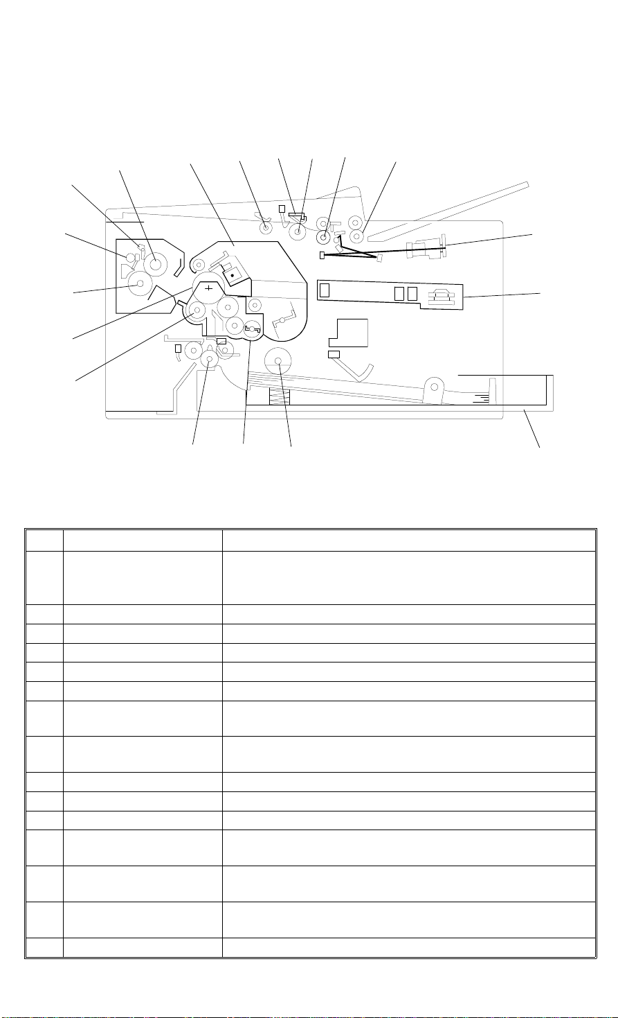
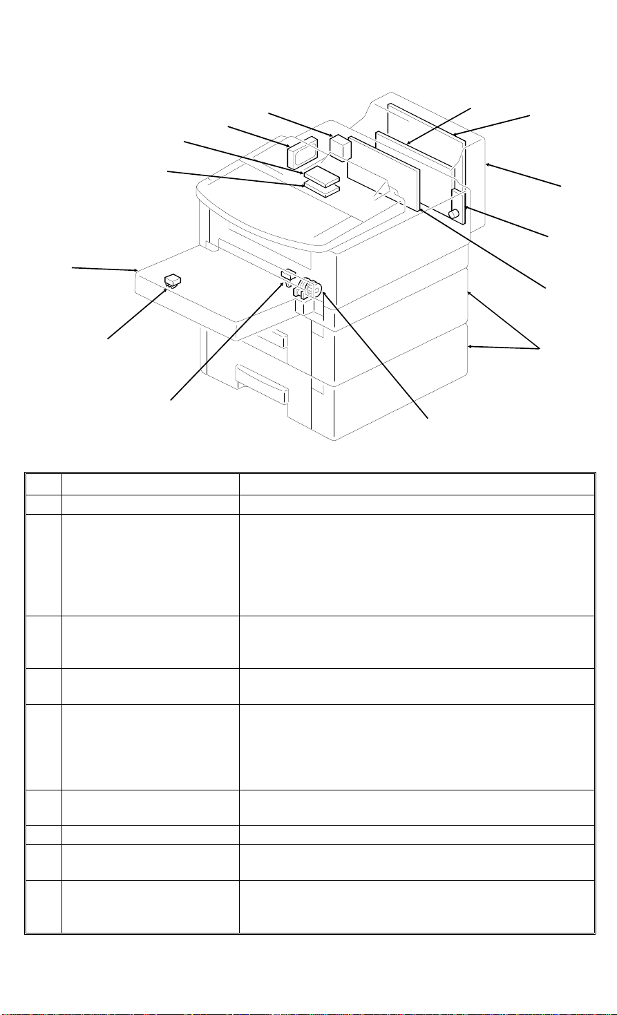
1.3. COMPONENT LAYOUT
1.3.1. Mechanical Components
4
5
3
10
6
9
8
7
11
12
13
14
15
16
17
No. Name Descr iption
Laser Unit This consists of the LDDR (Laser Diode Driver), focusing
1
SBU This scans the original.
2
R2 Roller Feeds the document through the scanner.
3
R1 Roller Feeds the document through the scanner.
4
Document Feed Roller Feeds the document into the scanner.
5
Separation Pad Allows one page into the scanner.
6
Pick-up Roller Picks up pages of the document from the document table
7
CTM (Cleaning Toner
8
Magazine)
Hot Roller Heat from this roller fuses the toner to the copy paper.
9
Hot Roller Strippers These take the paper off the hot roller after fusing.
10
Paper Feed-out Rollers These feed the paper out of the printer.
11
Fusing Pressure Roller This applies pressure to the paper during the fusing
12
OPC Drum The latent image is written to this organic photoconductor
13
Transfer Roller This applies a charge to the paper to pull the toner off the
14
Registration Roller This carries out the registration process.
15
lens, Fθ Lenses, hexagonal mirror motor, and other laser
optic components.
one at a time.
This consists of the toner cartridge, cleaning unit, used
toner tank, charge corona unit, and quenching lamp.
process.
drum.
drum and onto the copy paper.
2
1
18
H515V001.wmf
1-8

December 21st, 1995 OVERALL MACHINE INFORMATION
COMPONENT LAYOUT
No. Name Description
Development Unit This consists of the development roller, toner application
16
Paper Feed Rollers These pick up the top sheet of paper from the stack in the
17
Cassette (Standard) This holds up to 250 sheets of paper.
18
roller, toner supply bar, and transfer roller.
cassette and feed it into the printer.
1-9
5
4
19
20
27
28
OVERALL MACHINE INFORMATION December 21st, 1995
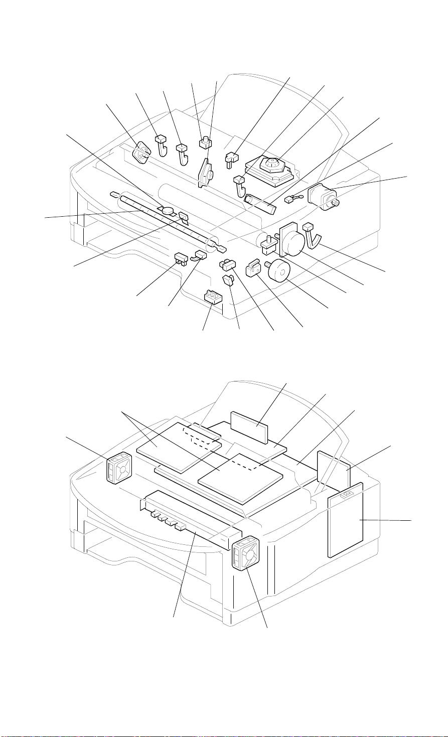
COMPONENT LAYOUT
1.3.2. Electrical Compone nts
6
10
7
8
9
11
3
13
12
14
30
15
16
17
2
1
24
23
22
21
H515V003.wmf
18
29
31
32
1-10
33
26
25
H515V004.wmf

December 21st, 1995 OVERALL MACHINE INFORMATION
COMPONENT LAYOUT
1. PCBs
No. Name Description
MFDU (M-zone Facsimile
Driver Unit)
27
MFCE (M-zone Facsimile
28
Control Engine)
NCU (Network Control
26
Unit)
OPU (Operation Panel
30
Unit)
PSU (Power Supply Unit) This board supplies power to the machine, and
25
LDDR (Laser Diode
7
Driver)
Power Pack This supplies high voltages to the corona wire, transfer
32
SBU The sensor on this board reads and converts the light
29
This board contains drivers for the motors, a dc-dc
converter, the energy saving mode cpu, and other drive
electronics.
This board controls the machine. It contains the main
cpu, flash ROM, system RAM, and so on.
This board contains a relay and switches for interfacing
the machine to the network and the handset.
This board controls the operation panel.
switches the fusing lamp on/off.
This board drives the laser diode.
roller, and development rollers.
reflected from the document into an analog video signal.
2. Motors
No. Name Description
Tx Motor This stepper motor drives the scanner.
1
Main Motor This brushless dc motor drives the drum, fusing unit,
23
Paper Feed Motor This stepper motor drives the registration roller and the
21
Hexagonal Mirror Motor This high-speed dc motor drives the hexagonal mirror
4
Ozone Fan Motor This removes ozone-laden air from the vicinity of the
31
Fusing Fan Motor This cools the interior of the machine.
33
development unit, and CTM.
paper feed mechanisms in the cassettes.
in the laser printer optics.
drum, and filters out the ozone.
1-11

OVERALL MACHINE INFORMATION December 21st, 1995
COMPONENT LAYOUT
3. Sensors
No. Name Description
Document Sensor This detects the presence of a document in the feeder.
5
B4-width Sensor This detects the presence of a B4 width document
9
A3-width Sensor This detects the presence of an A3 width document
10
Scan Line Sensor This detects when a page is approaching the auto
6
Toner End Sensor This detects when the toner has run out.
3
Paper Size Detector This detects the paper size installed in the cassette.
17
Paper End Sensor This detects when the paper in the cassette has run out.
24
Registration Sensor This detects when paper has reached the registration
16
Fusing Exit Sensor This detects when the paper has been fed out of the
19
Fusing Exit Cover Switch This detects whether the fusing exit cover is open or
18
Bypass Feed Sensor This detects when a sheet of paper has been inserted
15
(256mm, 10.1").
(297mm, 11.7").
shading position.
The user must install the correct size actuator.
roller.
printer.
closed.
into the bypass feed slot. Then the registration roller
feeds the paper a short distance into the machine to
prepare for printing, and stops.
4. Interlock Switches
No. Name Description
Interlock Switches: Fusing
Unit Cover, Top/Front
20
Cover
22
If the fusing unit cover is open, the +5VLD power
supply for the laser diode is interrupted. If the top
and/or front covers are open, the interlock switch
interrupts the +5VLD power supply for the laser diode
and the +24VD power supply for the power pack,
motors, and other components.
5. Others
No. Name Description
Stamper Ass’y This stamps a red circle on each page that is
8
Thermostat This interrupts the ac power to the fusing lamp if the
12
Thermistor This monitors the temperature at the hot roller surface.
14
Fusing Lamp The heat from this lamp fuses the toner to the paper.
13
Monitor Speaker This allows the user to listen to the condition of the
11
Zener Diode This ensures that the charge given to the drum by the
2
successfully fed through the scanner.
temperature of the thermostat surface exceeds 400°C.
telephone line.
charge corona wire does not exceed -750 volts.
1-12
47
December 21st, 1995 OVERALL MACHINE INFORMATION
COMPONENT LAYOUT
6. Optional Equipment
40
41
39
38
42
43
37
36
44
35
45
46
No. Name Description
Counter This counts the number of prints.
40
Printer Interface This allows the machine to be connected to a computer
as a laser printer. The following components belong to
37
IC Card (Upper Slot) The IC card connected to this slot increases the SAF
42
IC Card (Lower Slot) Either a Function Upgrade Card or a Fax On Demand
43
100 Sheet Cassette This increases the paper capacity by 100 sheets.
44
Paper Feed Units The machine can have up to two paper feed units. One
34
G4 Interface (CiG4) This interfaces the machine with an ISDN network.
35
Microphone jack for the
36
Fax On Demand kit
RS232C Interface Board This allows the machine to be connected to a computer
this unit. (Refer to the Printer Interface’s service
manual for details.)
38 - Controller Board
39 - Interface Board
memory capacity. Either a 2 MB or 4 MB DRAM card,
or an 80 MB hard disk (41) can be used.
Card can be used.
The following components belong to this cassette.
45 - Paper Size Detector
46 - Paper End Sensor
47 - Paper Feed Clutch
unit increases the paper capacity by 500 sheets.
This allows the users to record their own voice
messages for Fax On Demand applications.
as an external fax device, for example.
This option may not be available in some countries.
34
H515V510.wmf
1-13
OVERALL MACHINE INFORMATION December 21st, 1995
OVERALL MACHINE CONTROL
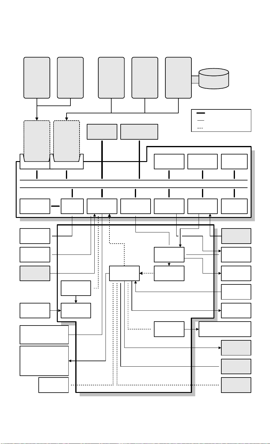
1.4. OVERALL MACHINE CONTROL
Fax On
Demand
Card
IC Card
(Type A)
Lower Slot
Video SRAM
(24kB)
SBU
Function
Upgrade
Card
IC Card
(Type B)
Upper Slot
VPP4F
Feature
Expander
RS232C
Interface
LPC
Feature
Expander
2M
4M
CiG4-SV
G4 Interface
MFCE
DATA/ADDRESS BUS
R144EFXL
Modem
MFDU
Interface
DRAM
(2MB)
SCP
HDD
80MB HDD
Bus Interface
Parallel Interface
Serial Interface
Flash ROM
(2MB)
Voice
A/D
Converter
SRAM
(128kB)
CG ROM
(512kB)
Microphone
(FOD)
LDDR
Laser Synch.
Printer
Interface
PSU
Hexagonal Mirror
Motor
Main Motor
Power Pack
CTM
Fan Motors
Mechanical
Components
Operation
Panel
Power
Saver CPU
DC/DC
Converter
EXIO1
EXIO2
Hybrid IC
DTMF
Receiver
MFPD
NCU
Speaker
Sensors
Clutches
Scanner Motor
Paper Feed Motor
Mechanical
Counter
100 Sheet
Cassette
PFUs
H515V501.wmf
1-14

December 21st, 1995 OVERALL MACHINE INFORMATION
OVERALL MACHINE CONTROL
The MFCE (M-zone Facsimile Control Engine) conta ins most of the log ical
components for overall system control, and direct interfa ces to the IC cards,
an RS232C interface*, and a G4 interface (CiG 4-S V). The MFDU (M-zone
Facsimile Drive Unit) has interfaces to the power sup ply, sensors, drive components, and optional equipment.
* The RS232C interface may not be available in some countries.
There are two cpus in the mach ine: the main cpu (SCP) on the MFCE an d
the energy saver cpu on the MFDU. In energ y saver mod e, the main CPU
switches off and the energy saver CPU takes over.
The 2 MB (16Mbit) flash ROM cont ains the system software, which can be updated through an IC card slot or from the remote control cente r u sing RDS.
The CGROM (Character Genera tio n ROM) conta ins all the cha ract er fo nts
used on the display and in rep orts.
The 2 MB DRAM is used for the SAF memory, ECM buffer memory, work
area, and page memory. The SAF memory can be extended by 2, 4, or 8 0
MB with an IC memory card or a hard disk.
The 128 kB SRAM contain s the user an d syste m para meters. This can be upgraded by 512 kB with th e fu nct ion upgrade card. These SRA Ms are battery
backed-up.
The MFCE has two IC card slots.
The upper IC card slot can ha ve one of the following:
• Feature Expander Type 140 - 2M (2 MB DRAM)
• Feature Expander Type 140 - 4M (4 MB DRAM)
• Feature Expander Type 140 - 80M (Hard disk interface with 1 MB
DRAM and 32kB SRAM*)
The lower IC card slot can have one of the follo wing :
• Fax On Demand Card (512 kB SRAM*)
• Function Upgrade Card (256 kB Flash ROM and 512 kB SRAM*)
• Flash/SRAM Data Copy Tool (Service Tool)
* The SRAMs in the IC cards are battery backed up, in case the the machine is turned off or
the machine goes into the 2-watt energy saver mode (referred to as Level 2 energy saver
mode in section 2-3). However, the data in these SRAMs are not guaranteed if the card is disconnected from the machine. Whenever the Fax On Demand card or Function Upgrade Card
needs to be removed for using the service tool, follow the instructions in section 4-1 to avoid
any data loss.
1-15

OVERALL MACHINE INFORMATION December 21st, 1995
VIDEO DATA PATH
1.5. VIDEO DATA PATH
1.5.1. Transmission (PSTN)
Scanner
Printer
Interface
Printer
(LDDR)
VPP4F
MFCE
Line Buffer
LPC
SAF
Memory
DCMMR
SCP
DCR
Page
Memory
Buffer
Memory
FIFO
ECM
Memory
CiG4
CiG4-SV
CODEC
Modem
To
PSTN
NCU
H515V502.wmf
Immediate Transmission:
Scanned da ta passes to the VPP4F, where the data un de rgoes analog/dig ita l
video processing, and is sent to the DCR block in the SCP thro ug h th e
DCMMR for compression.
The compressed data the n passes eit he r t o th e FIFO memory or to the EC M
memory, before it is sent to the telephone line through the modem.
Memory Transmission:
The processed video da ta from th e VPP4F passes to the DCMMR block in
the SCP, where the data is compressed into MMR format or kept as raw data,
then stored in the SAF memory.
At the time for transmission, the DCMMR block decompresses the data from
the SAF memory, then the DCR block compresses it again for transmission.
The compressed data the n passes eit he r t o th e FIFO memory or to the EC M
memory, then it is sent to the telephone line through the mod em.
Parallel Memory Transmission:
This feature allows the machin e to scan a do cume nt into the SAF memory
and to send the same docu men t simultaneously.
The machine stores the proce ssed video data in the SAF memory and sen ds
the data through the mo dem a t th e same time.
Refer to section 2.3.3 for more details ab ou t th is featu re.
1-16

December 21st, 1995 OVERALL MACHINE INFORMATION
VIDEO DATA PATH
1.5.2. Reception (PSTN)
Scanner
Printer
Interface
Printer
(LDDR)
VPP4F
MFCE
Line Buffer
LPC
SAF
Memory
DCMMR
SCP
DCR
Page
Memory
Buffer
Memory
FIFO
ECM
Memory
CiG4-SV
CiG4
CODEC
Modem
NCU
From
PSTN
H515V503.wmf
Data from the line passes to t he mod em t hro ug h the NCU. A ft er t he mod em
demodulates the data , the DCR block in th e SCP decompresses the data
from either the FIFO or the ECM memory.
At the same time, the demodu lat ed data is backe d up in the SAF memo ry, in
case of mechanical prob lems du ring print ing (this is known as subst itu te reception).
The decompressed da ta is then passed to the p ag e me mory for printing. Aft er
a page of data has been stored in the page memory, the data is sent to the
LDDR through the LCP for prin tin g.
1-17

OVERALL MACHINE INFORMATION December 21st, 1995
VIDEO DATA PATH
1.5.3. Transmission (ISDN)
To
Scanner
Printer
Interface
VPP4F
MFCE
Line Buffer
SCP
SAF
Memory
DCMMR
DCR
Buffer
Memory
FIFO
CiG4
CiG4-SV
CODEC
Modem
ISDN
Printer
(LDDR)
LPC
Page
Memory
ECM
Memory
G3
G4
NCU
H515V504.wmf
G4 Immediate Transmission :
Scanned da ta passes to the VPP4F, where the data un de rgoes analog/dig ita l
video processing, and is sent to the DCR block in the SCP thro ug h th e
DCMMR for compression.
The DCR block then compresses the data into MMR format, and passes it to
the CiG4-SV board for G4 transmission .
G4 Memory Transmission:
The video processed da ta from th e VPP4F passes to the DCMMR block in
the SCP, where the data is compressed into MMR format or kept as raw data,
then stored in the SAF memory.
At the time for transmission, the DCMMR block decompresses the data from
the SAF memory, then the DCR block compresses it again into MMR format.
The MMR compressed data then passes to the CiG4-SV board for tran smission.
G3 Transmission over an ISDN:
The analog data is con vert ed into PCM (Pulse Coded Modulation) fo rmat in
the codec, then sent over th e IS DN.
Parallel Memory Transmission:
This feature allows the machin e to scan a do cume nt into the SAF memory
and to send the same docu men t simultaneously.
The machine stores the proce ssed video data in the SAF memory and sen ds
the data through the CiG 4 board at the same time.
Refer to section 2.3.3 for more details ab ou t th is featu re.
1-18

December 21st, 1995 OVERALL MACHINE INFORMATION
VIDEO DATA PATH
1.5.4. Reception (ISDN)
From
Scanner
Printer
Interface
VPP4F
MFCE
Line Buffer
SCP
SAF
Memory
DCMMR
DCR
Buffer
Memory
FIFO
CiG4
CiG4-SV
CODEC
Modem
ISDN
Printer
(LDDR)
LPC
Page
Memory
ECM
Memory
NCU
H515V505.wmf
G4 Reception:
Data from the ISDN line passes to the SAF memory first. The n the data is
decompressed at th e DCR block in th e SCP, and sent to the page memo ry.
After a page of data has been store d in the page memory, the data is sent to
the LDDR through the LCP for prin tin g.
G3 Reception from the ISDN:
Data from the ISDN line first passes to the modem throu gh the codec, where
it is converted int o a n a na log sign al. After the mode m de mod ulates the data,
the DCR block in the SCP decomp resse s the data fro m eith er th e FIFO or the
ECM memory.
At the same time, the demodu lat ed data is backe d up in the SAF memo ry, in
case of mechanical prob lems du ring print ing (this is known as subst itu te reception).
The decompressed da ta is then passed to the p ag e me mory for printing. Aft er
a page of data has been stored in the page memory, the data is sent to the
LDDR through the LCP for prin tin g.
1-19

OVERALL MACHINE INFORMATION December 21st, 1995
VIDEO DATA PATH
1.5.5. Copying
Scanner
Printer
Interface
Printer
(LDDR)
VPP4F
MFCE
Line Buffer
LPC
SAF
Memory
DCMMR
SCP
DCR
Page
Memory
Buffer
Memory
FIFO
ECM
Memory
CiG4
CiG4-SV
CODEC
Modem
NCU
H515V506.wmf
Single copy
The scanned data passe s t o th e page memory after video processing in the
VPP4F. After a page of data has been stored in the page memory, the data is
sent to the LDDR through the LIF blo ck.
Multi-page copy
The scanned data passe s t o th e SA F memory af ter video processing
(VPP4F) and compression (DCMMR). Af ter all t he page s have b een st ore d in
the SAF memory, the data passes to the DCMMR block again for decompression, then it passes to the page memo ry for prin tin g.
1-20

December 21st, 1995 OVERALL MACHINE INFORMATION
VIDEO DATA PATH
1.5.6. Printing from the Optional Pri nter Inter fac e
Scanner
Printer
Interface
Printer
(LDDR)
VPP4F
MFCE
Line Buffer
LPC
SAF
Memory
DCMMR
SCP
DCR
Page
Memory
Buffer
Memory
FIFO
ECM
Memory
CiG4
CiG4-SV
CODEC
Modem
NCU
H515V507.wmf
After a page of data has been stored in the printer interfa ce’s page memory,
the data is sent to the LDDR through the LCP.
The page memory on the MFCE is not used for print ing .
1-21
 Loading...