

Ricoh FAX2700L Technical Bulletin flx7
Technical Bulletin No. F/LX7 - 001
Page 1/1
SUBJECT: ADF Mylar
PREPARED BY: K. Misugi
CHECKED BY: S. Fujii
CLASSIFICATION:
Action Required Revision of service manual
Troubleshooting Information only
Retrofit Information Other
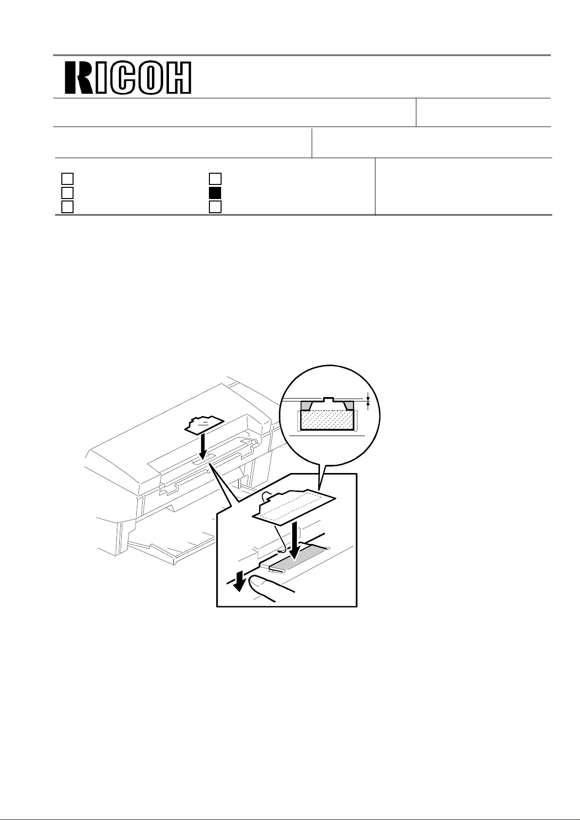
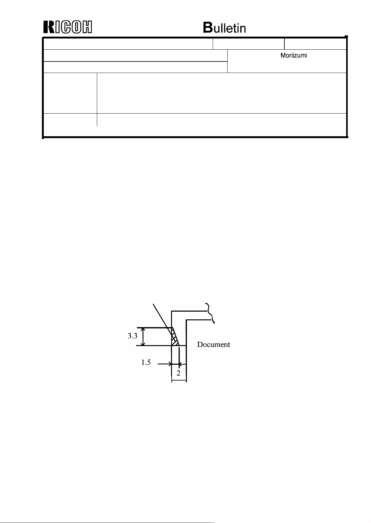
For customers who would like to use originals which contain silicone oil, place the mylar on the
Document Separation Pad as shown in the diagram below.
The ADF mylar will be available as a service part.
Part Number: H528 9500
FROM: 2nd Field Information Group,
MODEL: FX7
RICOH FAX1700L
NRG 9765, SAVIN FAX 3650
Infotec 3671
DATE:
1996. 10. 30.
QA Division

Page 1/1
Technical Bulletin No. F/LX7 - 003
SUBJECT: Print left margin from the optional paper feed unit
PREPARED BY: K.Moriizumi
CHECKED BY: S.Fujii
CLASSIFICATION:
Action Required Revision of service manual
Troubleshooting Information only
Retrofit Information Other
Symptom
The printed image shifts to left when printing from the optional paper feed unit.
The image is printed in the correct position when printing from the standard paper tray.
Cause
The initial value of the print left margin was fixed during the pre-mass-production.
However, the mechanical unit shifted the print left margin during the mass-production.
The print left margin for the standard paper tray was adjusted in the assembly line, but the
print left margin of the optional paper feed unit was not adjusted.
FROM: Quality Assurance Center
DATE:
15,Jan.1997
MODEL:FX7
RICOH FAX 1700L
NRG 9765,SAVIN FAX 3650
Infotec 3671
Countermeasure
The initial value of the print left margin for the standard paper tray and the optional paper
feed unit will be changed in order to match the mechanical unit. This change will be
implemented from the January production runs.
Action required
If the user makes a complaint about the print left margin from the optional paper feed unit,
adjust the print left margin for the optional paper feed unit by referring to the following
table.
RAM address Value Function
8002C0 [H] 06 [H] Print left margin (Standard paper tray)
8002C1 [H] 06 [H] Print left margin (Optional paper feed unit)
RC RE ASIA
* * *

TECHNICAL BULLETIN
Model: F/X7 Date: 15-Feb-97
No: 002
Subject: FX7 Service Manual Correction Prepared by: K.Misugi
From: 2nd field Information Group, QA Division Checked by: S.Fujii
Classification:
Troubleshooting
Mechanical
Paper path
Other ( )
Part information
Electrical
Transmit/receive
Action required
Service manual revision
Retrofit information
Section 1. OVERALL MACHINE INFORMATION
1.1. Specifications
Paper Size and Capacity
Incorrect Correct Remarks
Paper Feed Unit (Optional):
A4, Letter, Legal, F4
Paper Feed Unit (Optional):
A4, Letter, Legal
F4 size cannot be used with
the optional paper feed unit.
1/
Section 2. DETAILED SECTION DESCRIPTIONS
2.2.1. Printing Process - Overview
Incorrect Correct Remarks
Document Blade - 550V Doctor Blade -550V Illustration: H528D545.wmf
Development Roller (Bias):
- 300V
Development Roller (Bias):
- 280V
Development Roller bias has
been changed.
2.2.5. Development
1. Overview
Incorrect Correct
“During printing, a bias voltage of -300V is
applied to the development roller.”
“During printing, a bias voltage of -280V is
applied to the development roller.”
2. Development Bias
Incorrect Correct Remarks
Development roller:
-300V [B]
Development roller:
-280V [B]
Same as above.
TECHNICAL BULLETIN
2.3.2. Automatic Service Calls
1. Service Call Conditions
Descriptions Incorrect Correct
Service Call Conditions Sub-code address
80033C(H)
Hexagonal mirror motor
error
Fan motor failure Sub-code 52 Sub-code 51
2. Excessive Jam Alarms
Incorrect Correct Remarks
Then, the alarm is disabled
until either bit 3 or bit 4 of
address 80033D(H) is reset
to zero.
4. PM Call
Incorrect Correct Remarks
Default setting: 60,000
sheets
Sub-code 32 Sub-code 31
Then, the alarm is disabled
until either bit 3 or bit 4 of
address 8002DD(H) is reset
to zero.
Default setting: 30,000
sheets
Sub-code address
8002F9(H)
The last sentence on the
descriptions of the
Excessive Jam Alarms. The
RAM address is incorrect.
Section 4. SERVICE TABLES AND PROCEDURES
4.1.17. Printer Test Patterns (Function 11)
Incorrect Correct Remarks
Press a key from 0 to 4. Press the 0 or 1 key. Only 0 or 1 are selectable.
4.2. Bit Switches
Bit Switch Incorrect Correct
System Switch 04: Bit 5
OPC replacement level
The drum replacement
interval is programmed at
addresses 8001E5 to
8001E7(H).
The drum replacement
interval is programmed at
addresses 8001EE to
8001F0(H).
TECHNICAL BULLETIN
Scanner Switch 00:
Bits 2 and 3
Maximum transmittable
document length
4.5. Service RAM Addresses
RAM Address Incorrect Correct
8002F9(H):
Details of the service call
(hardware error)
80033D(H): Excessive jam
alarm
8003FD to 800404
Scanner Video Processing
Parameters
Bit 3 2 Setting
0 1 1200 mm
32(H): Mirror motor error 31(H): Mirror motor error
52(H): Fan motor error 51(H): Fan motor error
80033D(H) (address is
wrong)
8003FD to 800404(H)
(addresses are wrong)
Bit 3 2 Setting
0 1 1000 mm
8002DD(H)
800340 to 800347(H)
Section 5. PREVENTIVE MAINTENANCE
5.1. Special Tools and Lubricants
RAM Address Incorrect Correct
Flash/SRAM data copy tool
(P/N: A1939535)
Section 6. REPLACEMENT AND ADJUSTMENT
6.6. Image Adjustment
Incorrect Correct
"The RAM reset level 0 will reset all the
scan and print margin parameters to the
initial settings."
Flash/SRAM data copy tool
(P/N: A1939353)
"The RAM reset level 1 will reset all the
scan and print margin parameters to the
initial settings."
This information has already
been released.

TECHNICAL BULLETIN
Section 7. TROUBLESHOOTING
7.3. Service Call Conditions
Description Incorrect Correct
Mirror motor error Sub-code 32 Sub-code 31
SC Code 3-32 SC Code 3-31
Fusing unit fan motor error Sub-code 52 Sub-code 51
SC code 5-52 SC code 5-51

TECHNICAL BULLETIN
7.4. Error Codes
An error code has been added for an optional paper feed unit paper jam.
Code Meaning Suggested Cause/Action
9-50 Paper non-feed or jam at the paper
entrance
(With the paper feed unit.)
If the problem persists, replace the FCU.
Cross reference
Paper non-feed - Section 7-2-2
Jam at the paper entrance - Section 7-2-2
RICOH Technical Bulletin
Model: F/LX7 Date: 28-Feb-97
Subject: Scanner bottom margin Prepared by: K.Moriizumi
From: 2nd Technical Support Section Checked by: S. Fujii
Classification:
Troubleshooting
Mechanical
Paper path
Other ( )
Part information
Electrical
Transmit/receive
No: 004
Action required
Service manual revision
Retrofit information
Symptom
The scanner bottom margin is wider by a few millimeters.
Cause
A sheet has been added to the scanner cover to accurately reset the document exit
sensor starting from the November 1996 production run.
(H5291156:Sheet - Scanner Cover)
As a result, the document exit sensor resets accurately and quickly.
It may cause a wider blank space at the bottom of the scanned pages and the
omission of the trailing edges of the scanned pages.
1/1
Countermeasure
If the scanner bottom margin is too wide, please change the following RAM data.
Address Value
800298 10 → 16 (Copy Mode 100%)
804D67 00 → 07 (Memory Tx STD)
804D69 0B → 11 (Copy Mode 75%)
804D6B 0D → 13 (Copy Mode 85%)
804D6D 0F → 15 (Copy Mode 95%)
804D6F 13 → 17 (Copy Mode 125%)
804D71 17 → 1C (Copy Mode 150%)
804D73 1F → 1E (Memory Tx SSF)
804D75 07 → 00 (Memory Tx STD)
Note: Do not change the above RAM values on the machines in which the Scanner
Cover Sheet was not added.
RC RE ASIA
* * *

RICOH Technical Bulletin
Model: F/LX7 Date: 28-Feb-97
Subject: TTI on the System Parameter List Prepared by: K.Moriizumi
From: QAC 2nd Field Information Dept. Checked by: S. Fujii
Classification:
The programmed TTI is not printed in the middle of the system parameter list but at the
upper right corner because of the limited ROM capacity.
Troubleshooting
Mechanical
Paper path
Other (Information Only )
Part information
Electrical
Transmit/receive
No: 005
Action required
Service manual revision
Retrofit information
1/1
Technical Bulletin PAGE: 1/1
Model: FX7,LX7 Date: 15-Mar-97
Subject: ADF Solenoid control Prepared by: Y.Tamaoka
From: QAC 2nd Field Information Dept. Checked by: S. Fujii
Classification:
Troubleshooting
Mechanical
Paper path
Other ( )
Part information
Electrical
Transmit/receive
Action required
Service manual revision
Retrofit information
No: 007
SYMPTOM
The Document Pick-up Solenoid stays on even after document is fed out and this
causes overheating . This may result in warping of the operation panel cover and
damage to transistor Q4 on the FCU.
CAUSE
There is no software protection for the above condition.
This may happen if an original is fed in too far between the Document Pick-up
Roller and Separation Pad, but it is rare.
SOLUTION
1) Software Update
H5287120E for FX7, H5297120C for LX7
2) Adding a decal informing users not to forcibly insert documents (Under
preparation :The decal should be expectedly available at the beginning of March
1997)
RICOH Technical Bulletin PAGE: 1/1
Model: FX7 Date: 31-Mar-97
No: 006
Subject: SC Code Coreection Prepared by: Y.Tamaoka
From: QAC 2nd Field Information Dept. Checked by: S. Fujii
Classification:
Troubleshooting
Mechanical
Paper path
Other ( )
Part information
Electrical
Transmit/receive
Action required
Service manual revision
Retrofit information
Page 7-22
7.3 SERVICE CALL CONDITIONS
Current
Symptom Error Code Sub-code SC Code
Mirror motor error 9-23 32 3-32
Corrected to
Symptom Error Code
Mirror motor error 9-23
RC RE ASIA
* * *
Sub-code SC Code
31 3-31
T
H
echnical
B
ulletin
RTB Correction
Reissue date: 30-Sep-97
The items in bold italic have been corrected or added.
PAGE: 1/1
Model:
Subject:
From:
Classification:
Modification
Schedule
FX7
Drum Cartridge
QAC 2nd Field Information Dept.
Troubleshooting
Mechanical
Paper path
Other ( )
Date:
Prepared by:
Part information
Electrical
Transmit/receive
31-May-97
No:
K.Moriizumi
Action required
Service manual revision
Retrofit information
008
A
SYMPTOM
When the drum cartridge is replaced, if the top cover is not opened fully, paper jams will
occur.
CAUSE
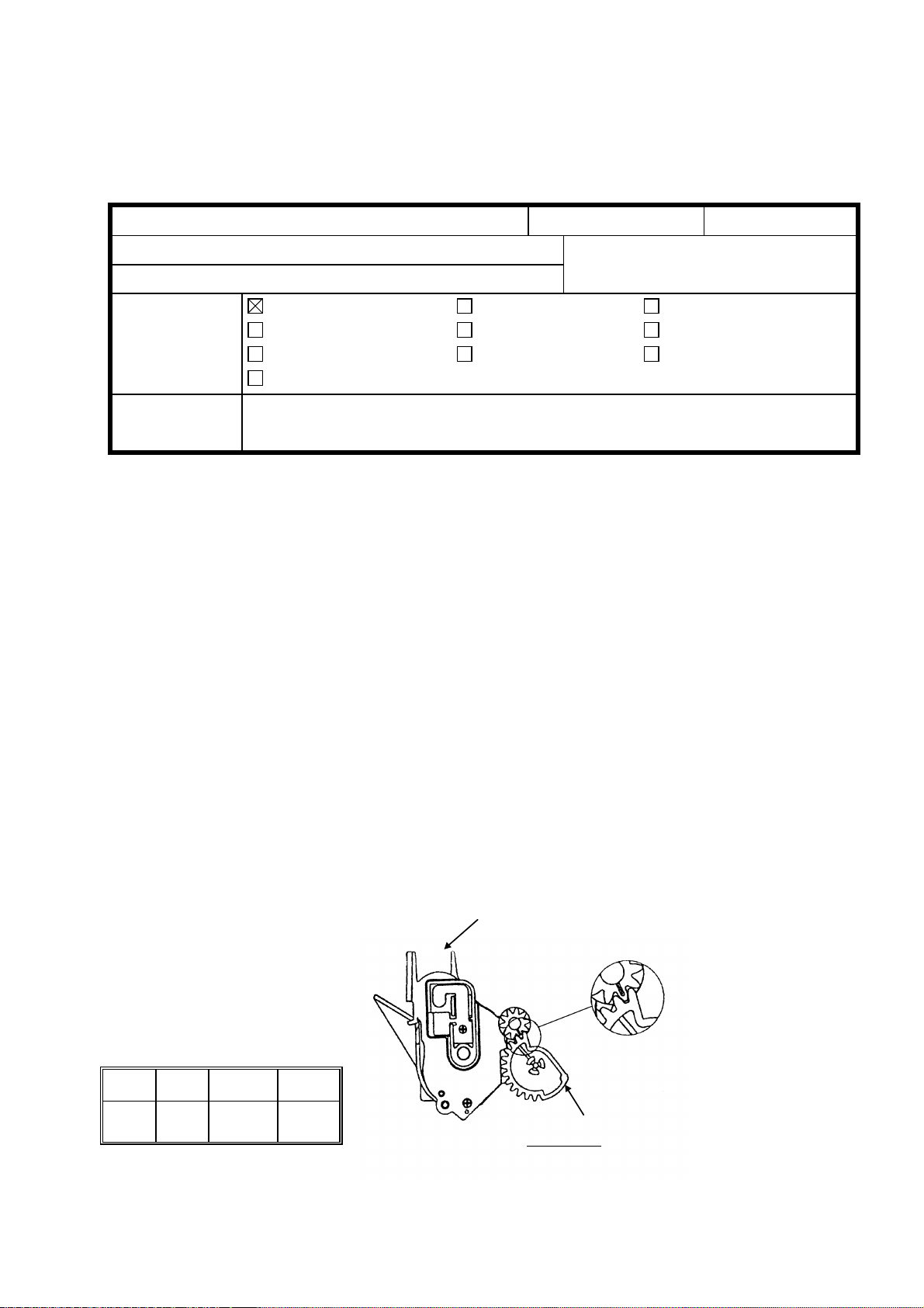
The drum cartridge gear comes off if the top cover is not opened fully.
SOLUTION
Instruct the customer to repair the drum cartridge gears in the following manner
1. Remove drum cartridge gear-1 from the drum cartridge.
2. Snap on drum cartridge gear-1 in the correct position.
3. Instruct the customer to open the top cover fully when installing the drum
cartridge.
We will prepare the drum cartridge gear as a service part. If the customer breaks the drum
cartridge gear by mistake, use a new one.
Drum Cartridge
RC RE ASIA
∗ ∗ ∗
Drum Cartridge Gear – 1
H5289500
5289501
WIINl
ModeI: FX7
Technical
Bulletin
Date:
31-May-97
No:
PAGE: 1/2
009
Subject:
From:
Classification:
Document Sensor
QAC 2nd Field Information Dept.
❑
Troubleshooting
❑
Mechanical
❑
Paper path
❑
Part information
❑
Electrical
❑
Transmit/receive
Prepared by:
K.
Moriizumi
❑
Action required
❑
Service manual revision
❑
Retrofit information
❑ Other ( )
Modification
Schedule
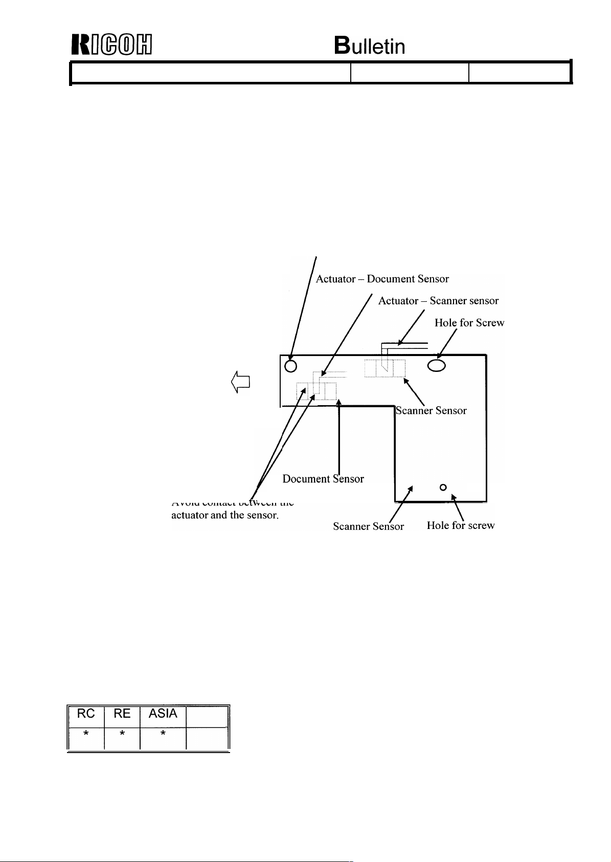
SYMPTOM
A document jam error occurs even though there are no documents in the ADF. This is
because the Document Sensor is stuck.
CAUSE
The actuator of the document sensor touches the sensor unit on the Scanner Sensor
Board.
I
From September, the scanner sensor board was shifted to the left during assembly,
However, the board might be shifted due to vibration during transportation.
From December, the document sensor actuator was changed to prevent contact with
the sensor.
Cut here
Sensor
Actuator
Kmml
Model:FX7
Technical
Bulletin
Date: 31-May-97
No:
PAGE: 2/2
009
SOLUTION
If the document sensor does not return to the initial position, please do the following.
Temporary Countermeasure
1. Loosen the screws of the Scanner Sensor Board.
2. Push the Scanner Sensor Board to the left side.
3. Tighten the screws.
Hole for Screw
Push the Scanner Sensor Board to the left.
(It can be moved only about 0.3 mm.)
Avoid contact be ween the
Permanent Countermeasure
1. Replace the Document Sensor Actuator.
The new part number is:
H5291160: Actuator – Document Sensor
RICOH Technical Bulletin PAGE: 1/1
Right rib
Two –side
Line A
H5293168
Model: F/LX7 Date: 15-Jun-97
Subject: Paper Tray Prepared by: K.Moriizumi
From: QAC 2nd Field Information Dept.
Classification:
Troubleshooting
Mechanical
Paper path
Other ( )
Part information
Electrical
Transmit/receive
Action required
Service manual revision
Retrofit information
No: 010
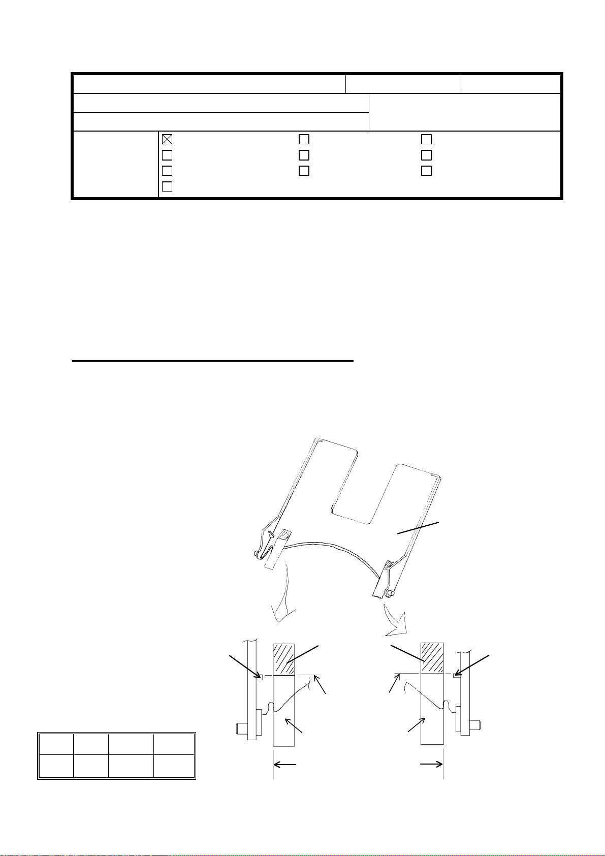
SYMPTOM
A paper jam occurs because the paper tray is in the wrong position.
SOLUTION
Sheets have been added to the paper tray as a countermeasure to prevent the paper tray
from being set in the wrong position. Please refer to the following installation procedure.
P/N : H5293168 (Sheet – Paper Tray)
Sheet – Paper Tray Installation Procedure
1. Put two-sided adhesive tape on the underside of the paper tray near the hinges along
the Line A and B and Line B and C as shown below.
2. Press down on the adhesive tape after application to remove any air bubbles.
Paper Tray Under Side
Left rib
adhesive tape
Line C
Line C
RC RE ASIA
* * *
Sheet-Paper Tray
Line B
RICOH Technical Bulletin PAGE: 1/2
Model: F/LX7 Date: 31-Jul-97
Subject: History of Software Changes Prepared by: K.Moriizumi
From: QAC 2nd Field Information Dept.
Classification:
# Reason/Problem H5287120 H5297120
1 The rotation time of the document exit roller has a
limited margin. So, the document exit roller might hold
the end of the last page of the document.
2 If the size of paper in the Optional Paper Feed Unit is
different from the setting , a paper size error for the
Standard Tray occurred instead of for the Optional
Paper Feed Unit.
3 Spelling correction. D A
Troubleshooting
Mechanical
Paper path
Other (Software History)
Part information
Electrical
Transmit/receive
Action required
Service manual revision
Retrofit information
(Suffix)
No: 011
D
(Suffix)
D A
A
4 Correction for Spain and Switzerland to meet
regulations.
5 Garbage data is inserted in the first ECM frame
occasionally. But, the garbage data is not inserted in the
frame that is transferred again.
6 The printed image shifts to the left when printing from
the Optional Paper Feed Unit. (See RTB No. F/LX7-003)
7 The received page is printed out twice for non–ECM and
direct reception mode if a communication error has
occurred.
8 The engine version is always printed as “00” on the
System Parameter Report.
9 The Distinctive Ring function is printed on the User
Parameter List (Europe/Asia).
10 The scanner bottom margin is a few millimeters wider
(See RTB No. F/LX7-004).
11 The DIS frame description is always printed as
“V17 14. 4K W: A4 OMS (1/1 1/1)” on the protocol dump
list for PC Fax reception (Class 1) mode. The DIS Hex
Code dump is correct.
D A
D A
D A
D A
D A
D A
D B
– B
12 Correction for Spain to meet regulations. (The default
value for polarity change detection was changed so that
it is now enabled.)
RC RE ASIA
E C

RICOH Technical Bulletin PAGE: 2/2
Model: F/LX7 Date: 31-Jul-97
13 Document Pick-up Solenoid problem
(See RTB No. F/LX7-007)
14 It is impossible to send the document after the machine
detected a ringing signal if the Distinctive Ring function
is enabled.
15 The AI Short Protocol function is disabled after redialing. E C
FX7:
H5287120
Suffix D January, 1997 1B27/BEEF/5C38
Suffix E February, 1997 42B3/BEEF/83C4
Implementation Check Sum
(Total/Boot/Main)
No: 011
E C
E C
LX7:
H5297120
Suffix A November, 1996 8412/BEEF/C523
Suffix B January, 1997 8ABE/BEEF/CBCF
Suffix C February, 1997 96A7/BEEF/D7B8
Implementation Check Sum
(Total/Boot/Main)
RICOH Technical Bulletin PAGE: 1/1
Model: F/LX7 Date: 31-Jul-97
Subject: Tapping Screws Prepared by: K.Moriizumi
From: QAC 2nd Field Information Dept.
Classification:
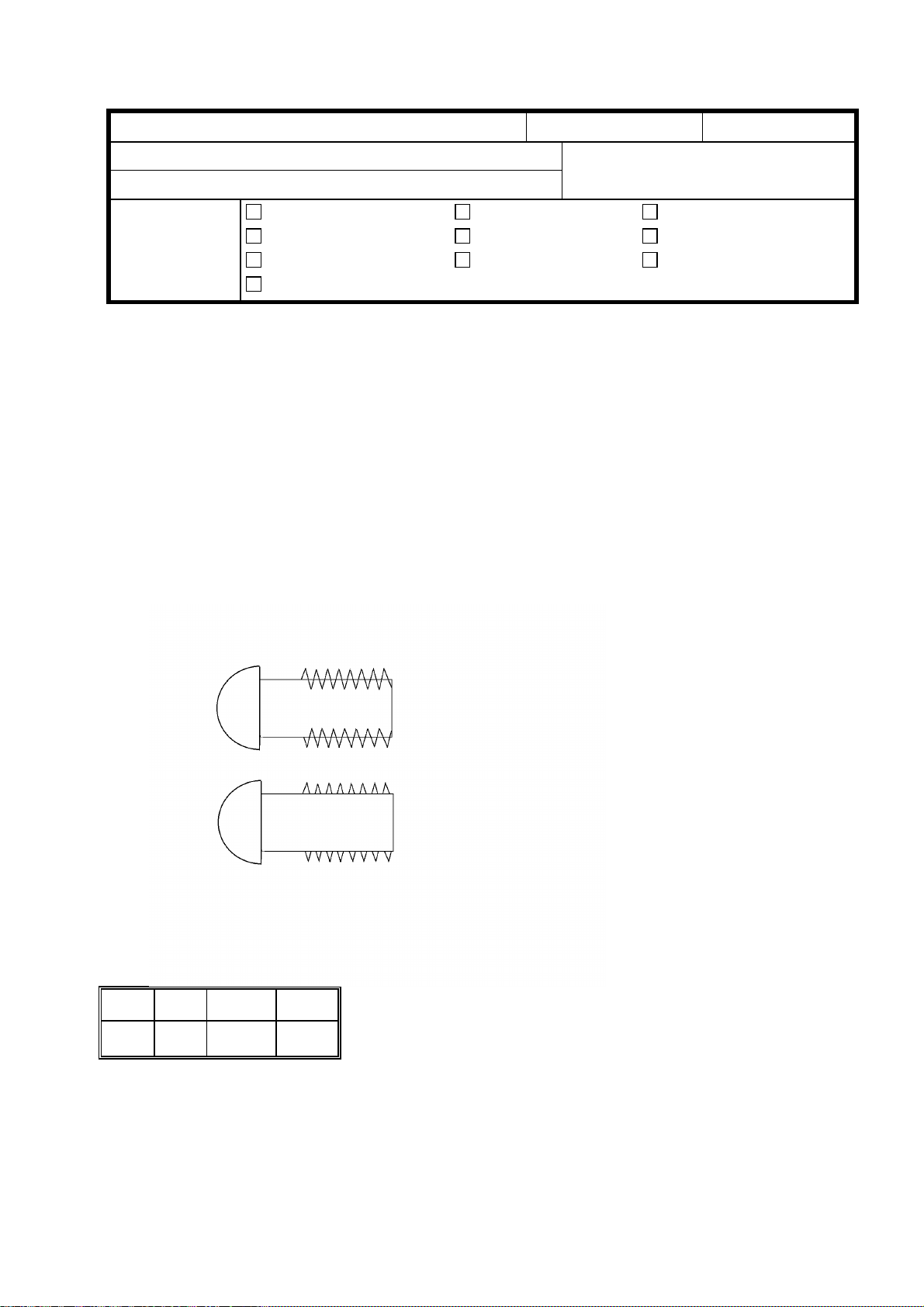
There is no tapping hole on the brackets which are service parts, because tapping screws
are used for the bracket.
The tapping screw is similar to a normal Phillips head screw. The pitch of the tapping
screw is the same as that of a normal screw; see below.
Troubleshooting
Mechanical
Paper path
Other ( )
Part information
Electrical
Transmit/receive
Action required
Service manual revision
Retrofit information
No: 012
Action required
1. Distinguish between the tapping screw and the normal screw by referring to the
following drawing.
2. Use the same tapping screw in the same place to attach the bracket.
RC RE ASIA
Normal Screw
Tapping Screw
 Loading...