

Ricoh FAX2700L SPECIFICATIONS PIF100

PRINTER INTERFACE
TYPE 100
TYPE 130
SERVICE MANUAL
July 10th , 1995
Subject to change.

Trademark Notices
Epson and Epson ESC/P are registered trademarks of Seiko Epson Corporation.
Epson LQ-2500, Epson FX-800/1000, Epson FX-86e/286e, Epson GL, Epson LQ, Epson FX,
Epson LQ-1050/850, Epson LQ-500, Epson LQ-1500, EpsonFX-85, Epson FX-80, Epson GL
Identity Card, Epson Roman T, and Epson Sans Serif U are are registered trademarks of Epson America Inc.
Action Laser and SelecType are trademarks and EPSON Connection is a service mark of Epson America, Inc.
EpsonScript and EPSON Talk are trademarks of Epson America Inc.
IBM and IBM PC are trademarks of International Business Machines Corporation.
HP Laser Jet, HP Laser Jet+, HP Laser Jet 500, HP Laser Jet series II, HP Laser Jet IIP, HP
Laser Jet series III, HP Laser Jet IIIP, HP Laser Jet IIISi are trademarks, and Hewlett-Packard
and PCL are registered trademarks of Hewlett-Packard Company.
LocalTalk, TrueType, AppleTalk, Macintosh, and LaserWriter are trademarks of Apple Computer, Inc.
Centronics is a trademark of Centronics Data Computer Corporation.
PostScript is a trademark of Adobe Systems Inc.
ITC Zapf Dingbats, ITC Avant Garde, ITC Bookman, ITC Zapf Chancery are registered trademark of International Typeface Corpor ation.
Bookman and Cantury Schoolbook are registered trademarks of Kingsley-ATF Type
Corporation.
Bitstream is a registered trademark of Bitstream Inc.
Speedo and FaceLift are trademarks of Bitstream Inc.
CG Times is a product of AGFA Compugraphic, a division of AGFA Corporation.
Univers, Times, Helvetica Narrow and Palatino are U.S. registered trademarks of Linotype
AG and its subsidiaries.
Phoenix, PhoenixPage, and Phoenix MultiGray are registered trademarks of Phoenix Technologies Ltd.
MS-DOS and Windows are registered trademarks of Microsoft Corporation.
July 10th, 1995 OVERALL INFORMATION
CONTROLLER SPECIFICATIONS
1. OVERALL INFORMATION
1.1. CONTROLLER SPECIFICATIONS
Item Specifications
Resolution 300 x 300 dpi
RAM Capacity 1.0 MB (Standard)
Upgradable to 2, 3, or 5 MB
Emulation Standard:
HP LaserJet 4L
ESC/P
ESC/P
HP GL/2
Optional:
PostScript
Resident Fonts 21 scalable fonts and 3 bitmap fonts
(Refer to the operator’s manual for more details.)
Paper Size
Note: All the acceptable sizes
must be in portrait orientation.
Host Interface Standard:
A4
A5
B5
LT (Letter)
HLT (Half letter)
LGL (Legal)
GLT (Government letter)
GLG (Government legal)
EXE (Executive)
F4
MON (Monarch)
C10 (Commercial 10)
DL
C5
IB5 (International B5)
C6
Bi-Centronics
Optional:
LocalTalk
®
24-pin printer emulation (LQ ® mode)
®
9-pin printer emulation (LX ® mode)
TM
emulation (LJ4L mode)
TM
emulation (EPSON GL/2 ® mode)
TM
Level 2
TM
parallel interface x 1
TM
Interface x 1
1.2. ENGINE SPECIFICATIONS
Item Specifications
Resolution 300 x 300 dpi
Print Speed (Engine Speed) Up to 10 ppm (Letter or A4)
Warm-up Time 20 seconds or less at normal temperature
Paper Size The available paper sizes are not the same as those
available with the controller. They depend on the
machine’s hardware specifications.
Refer to the operator’s manual for details.
1-1
OVERALL INFORMATION July 10th, 1995
BLOCK DIAGRAM AND DATA PATH
1.3. BLOCK DIAGRAM AND D AT A PA T H
FDU
FCE
Fax
Page
Memory
PSTN
Printer Interface
Controller PIF-L
Firmware
CPU CPU
NCU
Modem
Page
Memory
ADDRESS/DATA BUS
Cartridge
(Optional)
Font or PostScript
Compatible
Bi-Centronics I/F
PC-AT
LocalTalk I/F
Macintosh
(Optional)
Video/Command Interface
CPU
Laser Unit
H144V501.wmf
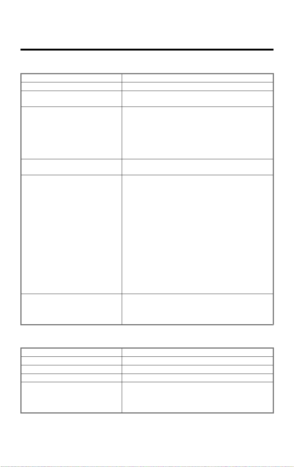
The printer interface unit con sists of a cont rolle r boa rd an d an inte rfa ce bo ard
(PIF-L).
The controller has a CPU, a ROM for the firmware, a page memory, an optional cartridge int erf ace, and up to two host interfaces (a standard
Bi-Centronics TM interface and an optional LocalTalk TM interface). Refer to
the controller specifications for details.
The PIF-L also has a cpu to emulate the controller commands and display
text on the fax machine’s hardware. For example, if the fax machine is not capable of using Legal size pape r, the PIF-L modifies the display text so that
the user cannot choose the Legal size pa pe r for printing.
Data Path
The controller’s CPU interprets the print dat a fro m the host compu te r and
writes an imaginary page in the page memory. After a page of data has been
stored in the memory, the controller transfers the data to the fax machine’s
CPU. Then, the fax machine ’s CPU passes the data directly to the laser unit
for printing.
The interface between the controller and the fax machine is known as the
“video interface”. This interface specifies the data transfer timing and handshaking procedure .
1-2

July 10th, 1995 OVERALL INFORMATION
POWER DISTRIBUTION
Dual Access
Since the printer resources are shared for printing fax messages and computer printouts, the machine is designed to do multiple tasks at the same time.
If a fax massage is coming in while th e mach ine ’s printer is busy for printing
from the controller, the machine will receive the fax message into SAF memory. After printing from the con troller has finished, the machine will print the
fax message from the SAF memory.
If a print request is made from the ho st comp ut er while the fax machine’s
printer is busy for fax messages or repo rts, the print data will be held in the
page memory on the controller. After printing has finished, the mach ine will
switch the printer resources to the controlle r for prin tin g. In this case, if the
print data size exceeds the controller’s memory size, the print data is spooled
in the host computer (if the computer’s operating system or the application
has a print spooler functio n).
1.4. POWER DISTRI BUTI O N
+24V and +5V are supplied to th e printer interface unit from the fax machine.
The PIF-L th en gen era te s an anot he r +5V sup ply fo r it s CPU and the cont roller.
1-3
July 10th, 1995 DETAILED SECTION DESCRIPTIONS
CONTROLLER
2. DETAILED SECTION DESCRIPTIONS
2.1. CONTROLLER
2.1.1. Print Density Control
2.1.2. Bi-Centronics TM Interface
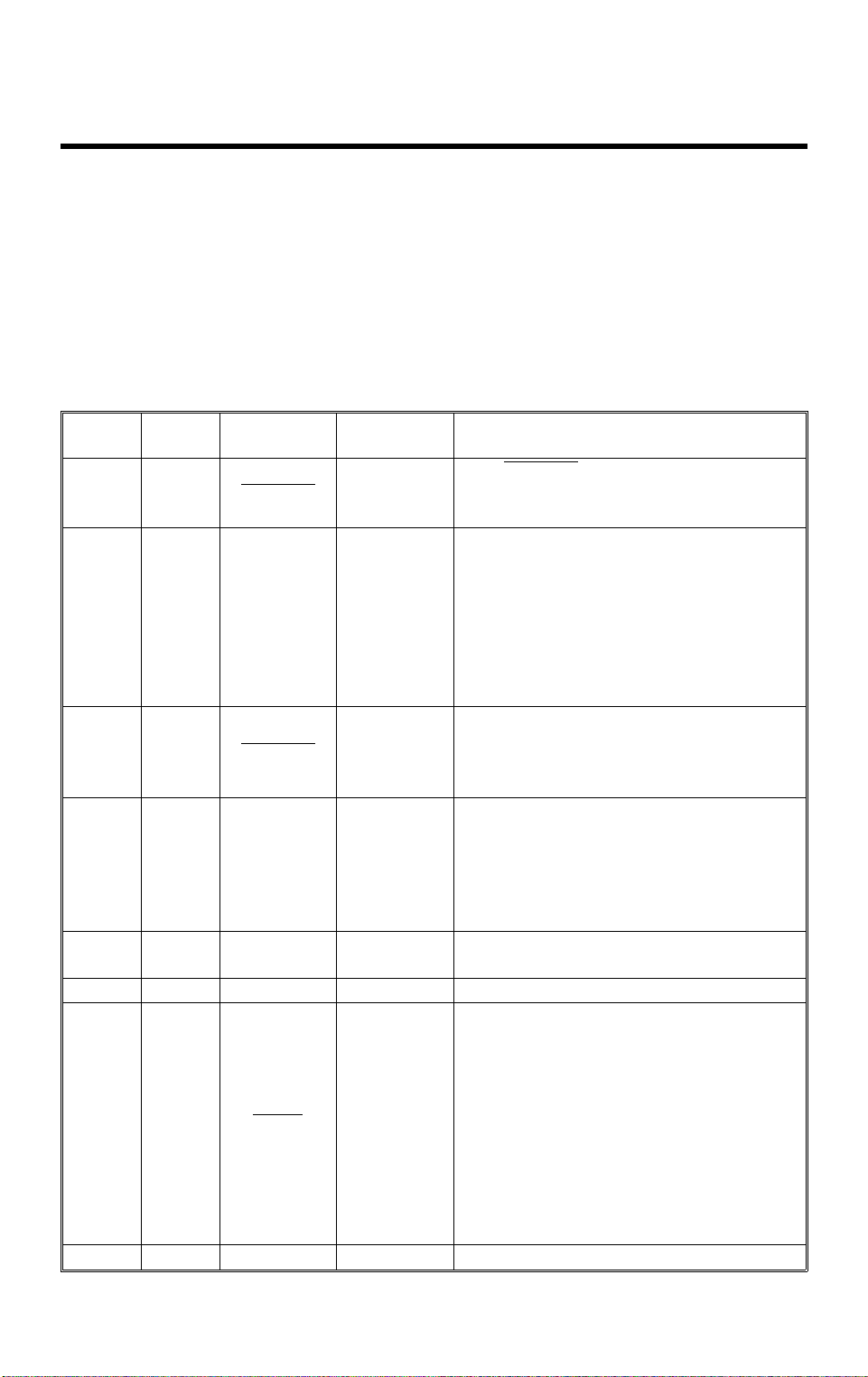
The parallel interface conne cto r pin assignments and a description of the interface signals are shown in the table below.
Signal
Pin
119
2
3
4
5
6
7
8
9
10 28
11 29 BUSY OUT
12 30 PE OUT
13 — SLCT OUT
14 —
15 — NC —
Return
Pin
20
21
22
23
24
25
26
27
Signal Direction Description
STROBE IN
DATA1
DATA2
DATA3
DATA4
DATA5
DATA6
DATA7
DATA8
ACKNLG OUT
AUTO IN
IN
IN
IN
IN
IN
IN
IN
IN
STROBE pulse for reading data. The
The
pulse width must be at least 0.5 µs at the
receiving terminal.
These signals represent parallel data bits
1 to 8. Each signal is at the HIGH level
when the data is a logical 1 and LOW
when it is a logical 0.
About a 10 µs pulse width. LOW
indicates that data has been received
and the printer is ready to accept more
data.
A HIGH signal indicates that the printer
cannot receive data. The signal goes
HIGH in the following cases:
1. During printing
2. When off line
3. During a printer-error state
A HIGH signal indicates that the printer is
out of paper.
Available only for bidirectional use.
Available only for bidirectional use.
A LOW signal enables automatic line
feed upon receiving a CR signal. This
signal is detected only when the machine
has just been turned on, or when the
printer interface is initialized.
In ESC/P
CR operation in accordance with the
SelecType
In HP
ignored.
Not used
®
mode, this signal effects a
TM
TM
setting.
mode, this signal is always
2-1

DETAILED SECTION DESCRIPTIONS July 10th, 1995
CONTROLLER
Signal
Pin
16 — GND —
17 —
18 — NC —
19~30 — GND —
31 — INIT IN
32 —
33 — GND —
34 — NC —
35 — +5V —
36 —
Return
Pin
Signal Direction Description
Logic ground level
CHASSIS
GND
ERROR OUT
SLCTIN IN
—
Chassis ground, which is connected to
the signal ground.
Not used
Twisted-pair return signal ground level.
When this signal goes LOW, the printer
controller ignores the
This signal goes LOW when the printer is:
1. Out of paper
2. In an error state
3. Off line
Same as for Pins 19~30
Not used
Pulled up to +5V through a 1KΩ resistor.
Available only for bidirectional use.
STROBE signal.
Note: • All interface conditions are based on TTL levels. Both the rise and
fall times of each signal must be less than 0.2 microseconds.
• Data transfer must be carried out by observin g th e ACKNLG or
BUSY signal.
(Data transfer to this printer can be carried out only after receipt of
the ACKNLG signal or when the level of the BUSY signal is LOW. )
• The "Direction" column refers to the direct ion of signal flow as
viewed from the printer.
• Return denotes the twisted-pa ir re tu rn to be con ne cte d at sig nal
ground level.
For the interface wiring, be sure to use a twist ed-pair cable for
each signal and to complet e the connection on the return side.
• The ACKNLG pulse width varies.
2-2
July 10th, 1995 DETAILED SECTION DESCRIPTIONS
CONTROLLER
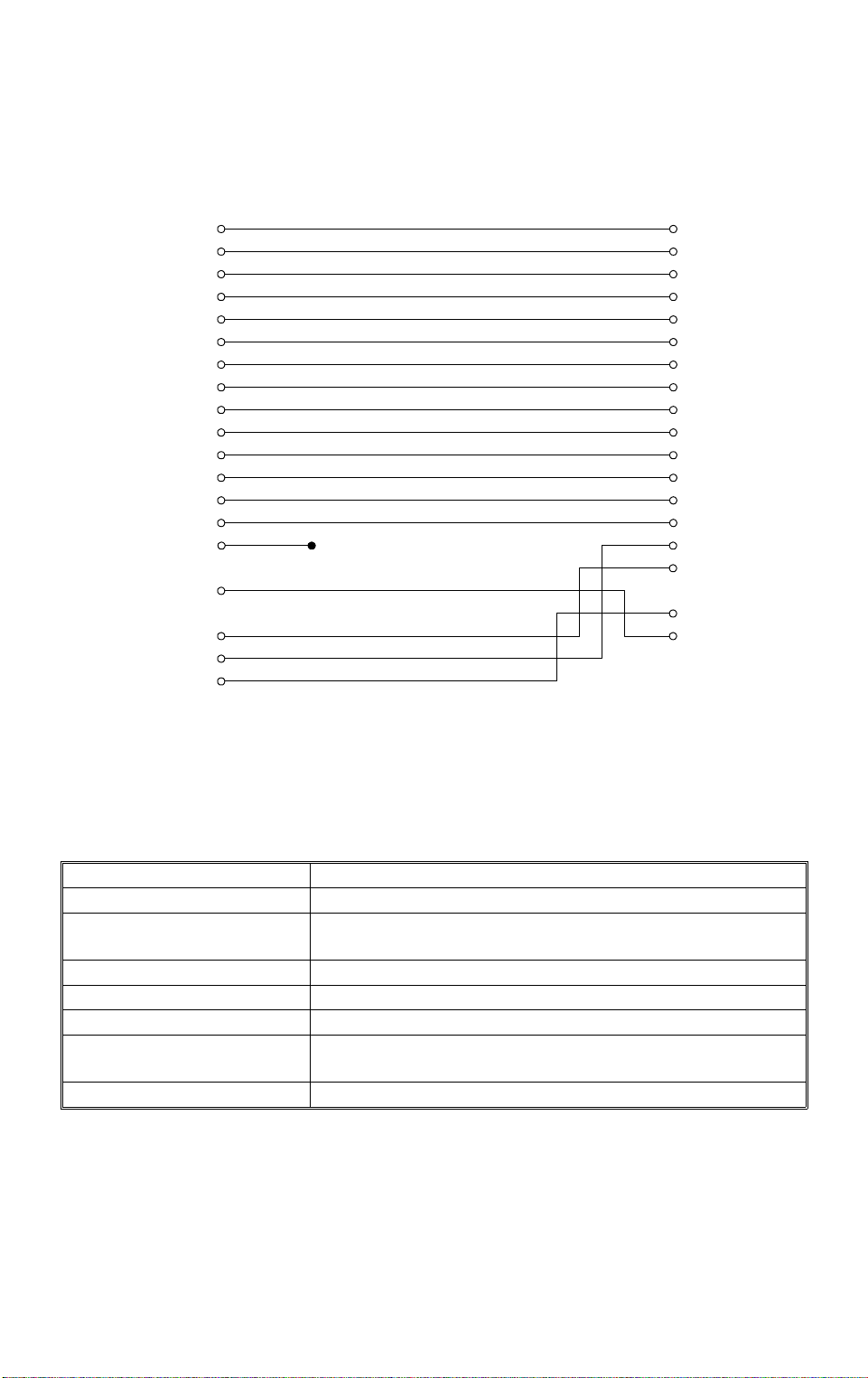
To enable bidirectional parallel interface communica tio ns be twe en the print er
and computer, set the connector pin assignments as follows:
Printer Interface Computer
1
2
3
4
5
6
7
8
9
10
11
12
13
14
17
•
31
32
36
Chassis GND
• 16, 19—30, 33 connected to GND
1
2
3
4
5
6
7
8
9
10
11
12
13
14
15
16
17
18—25
H144d501.wmf
2.1.3. LocalTalk TM Interface (Optional)
Specifications
Compatibility Phase 1 and phase 2
Baud rate 230.4 kbps
Topology Parallel bus, low-resistance transformer isolated, floating
ground.
Signaling standard EIA standard RS422, balanced voltage
Signal encoding FMO (bi-phase) space
Frame format SDLC (Synchronous Data Link Control)
Node identification AppleTalk
action required.
Cabling AppleTalk
TM
logical address is self-configuring; no user
TM
8-pin mini DIN
2-3

DETAILED SECTION DESCRIPTIONS July 10th, 1995
PIF
2.2. PIF
Controller PIF-L
5LSYNC
5VSYNC
5PRRDY
IC4
SWINT
PPRDY
RESET
CONNECT
LCD/KEY DATA
SERIAL CLOCK
CTBSY
COMMAND SERIAL DATA
STSBSY
STATUS
Print Density Adjustment
CPU
NORMAL
DARK
Circuit
5PRINT
5CPRDY
FDU/FCE
on the
Fax Machine
5PIFRESET
1INTPR
SERIAL CLOCK
SERIAL DATA
LIGHT
5LGATE
VIDEO SIGNALVIDEO SIGNAL
Printer Interface Unit
FAX
H144D502.wmf
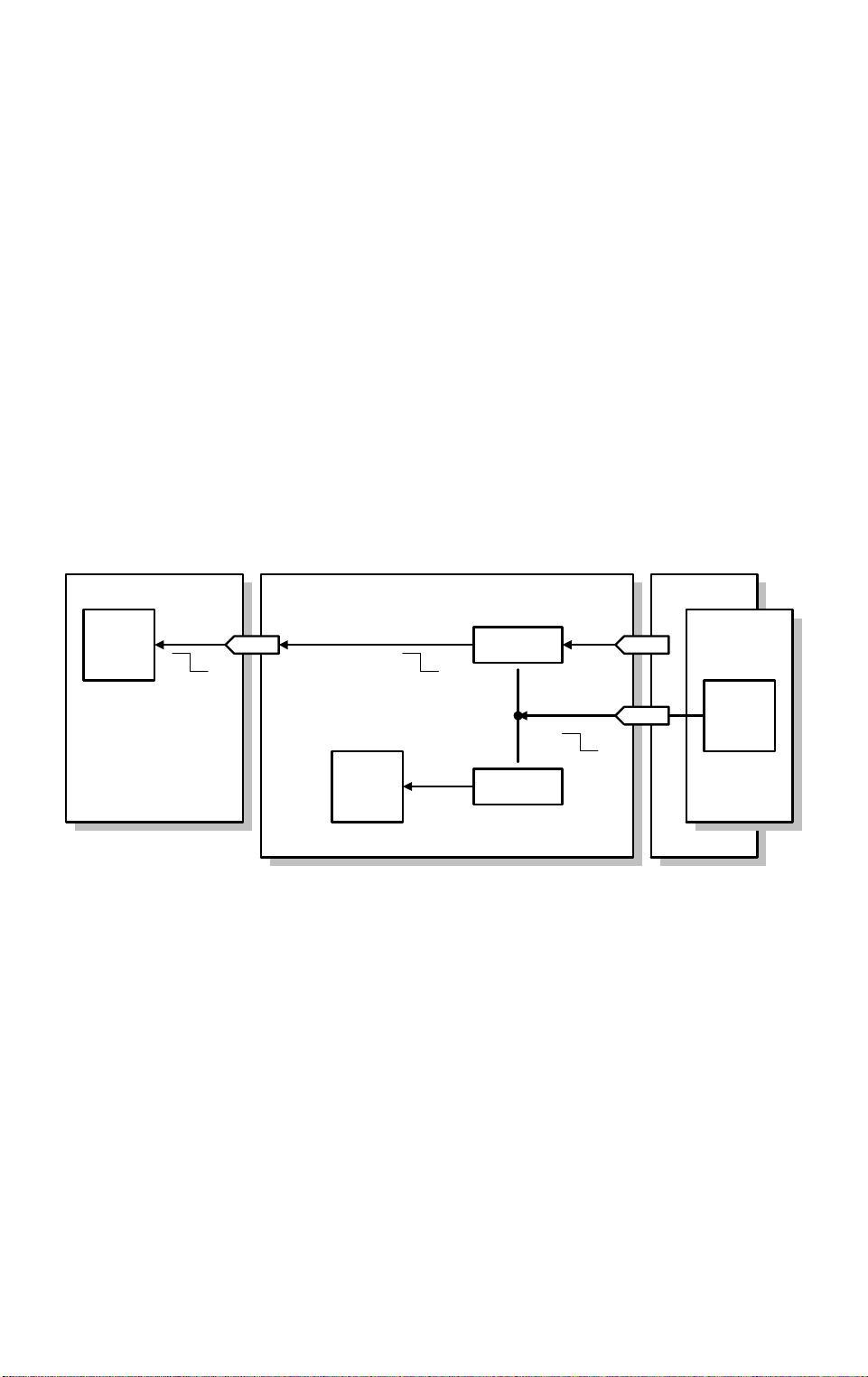
The CPU on the PIF-L works as a interpre te r (emula to r) bet wee n the prin ter
controller and the fax machine.
2.2.1. Command and Status Signals
The controller sends vario us commands to the fax machin e through the CPU
on the PIF-L for requesting hardware status (e.g. , casse tte paper size, jam,
toner end) and for specif ying a cassette for printing. The fax machine responds with a status signal.
The CPU on the PIF-L emulates the comman ds fo r fax machine’s hardware
specifications (e.g, some models can only have one cassette).
2-4
July 10th, 1995 DETAILED SECTION DESCRIPTIONS
PIF
2.2.2. K ey/Display Emu la tion
While the user is using the printer function from the fax machine, the fax machine’s keys and LCD are con ne cte d to the print er controller through the CPU
on the PIF-L.
Because the cap abilities of the controller and the fax machine are not the
same (for example, Monarch pa per is ava ilab le with the cont roller, but not
with the fax machine), the PIF-L emulates the user key operations fo r the controller and the display text s t o th e fa x ma chin e, so that the user cann ot select
settings that th e fa x machine is not capable of.
2.2.3. Print Density Control
The controller is capable of prin t density adjustment using the Leve l 2 menu .
Depending on the density sett ing sent from th e controller, the PIF-L adjusts
the pulse width for each pixel.
2.2.4. Printer Interface Re set
FDUPIF-LController
CPU
+5V
CN5-1,2
+5V +5V
+5V
CPU
RESET
DC/DC
Converter
Reset Circuit
+24V
5PIFRESET
+5V
CN1-20
CN1-2
FCE
CPU
H144D504.wmf
If the fax machine’s CPU activates the 5PIFRESET signal, the reset circuit on
the PIF-L resets the CPU on the PIF-L, and the DC/DC converter on the PIFL shuts down the +5V supply to the Controller board.
The procedure for totally re set tin g th e prin te r inte rfa ce is described in chapter
4.
2-5
 Loading...