

Page 1
q
Series 9 Operation Manual • Rev 2.00
Series 9
OPERATION MANUAL
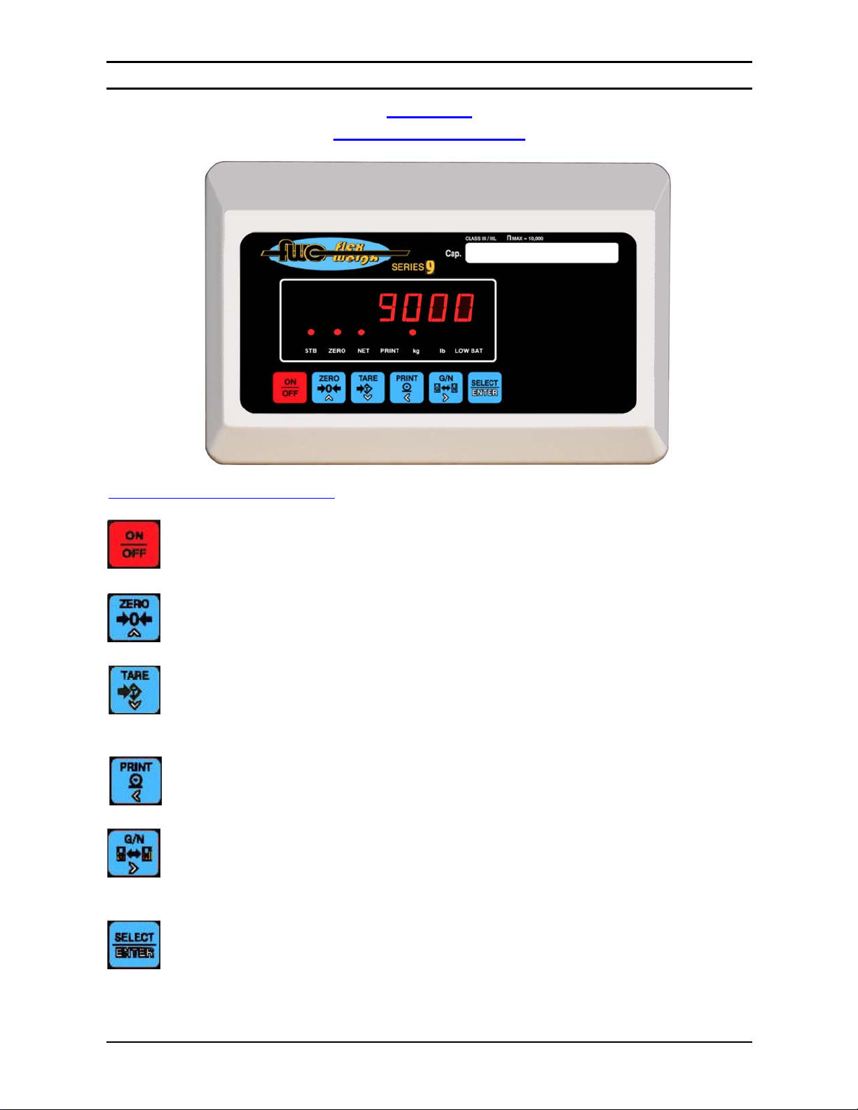
FUNCTIONS OF THE KEYS
ON / OFF
Used to switch the indicator ON and OFF.
ZERO key.
Used to Zero the indicator when the weight display is stable.
TARE key.
Used to remo ve the container weight value from the weight indicator. When pressed with
the weight on the scale at a stable condition, this tare value will be stored and subtracted
from the gross weight to indicate a net weight display of zero.
PRINT key.
Used to print out the data (with optional printer).
G/N key.
Used to toggle the Weight display between the Gross weight value and the Net weight
value.
Select / Enter key.
Used to T oggle the weight unit display between the Primary weight unit and the Secondary
weight unit according to how the unit is setup, su ch as (kg & lb), (kg & oz), (g & lb),
(g & oz), (lb & oz).
key.
FlexWeigh
Page 1 of 4
Page 2
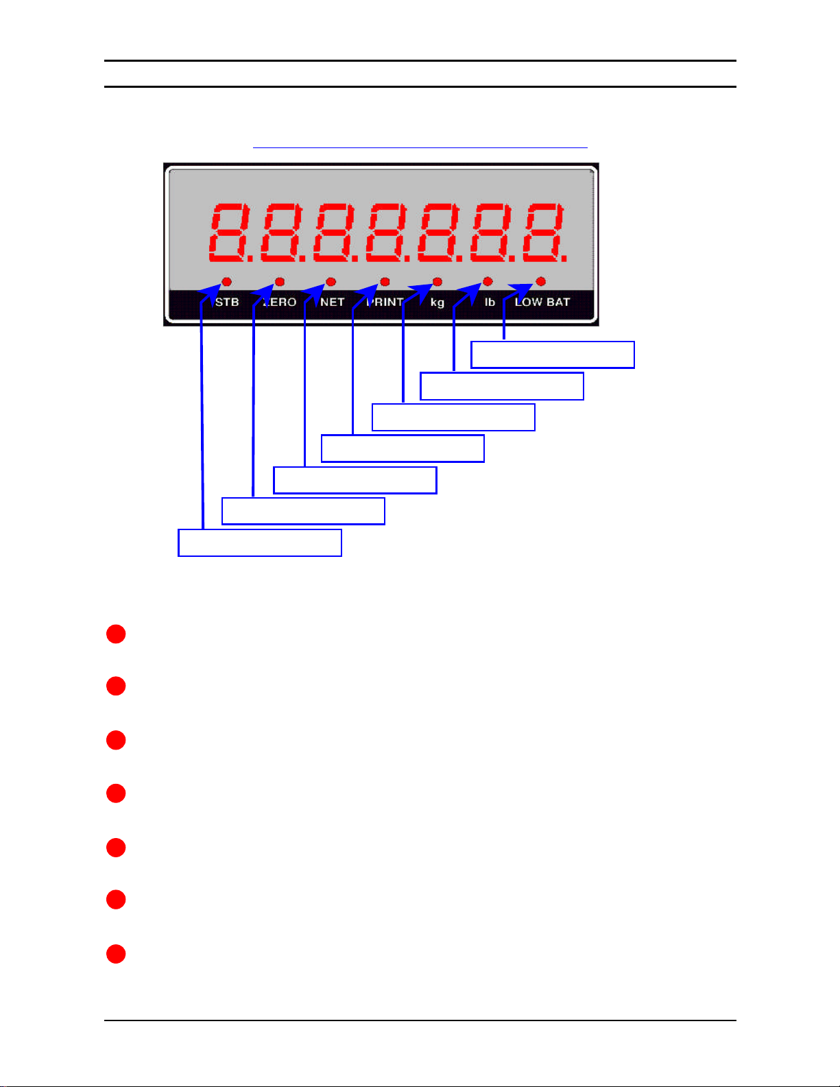
Low Battery Indicator
Pound Unit Indicator
Kilogram Unit Indicator
Print Stat us Indicator
Net Mode In
dicator
Zero Status Indicator
Stable Status Indicator
q
Series 9 Operation Manual • Rev 2.00
FlexWeigh
Explanation of Status LEDs’ Indication
There are a total of 7 LED lamps in a row just below the 7-segment LEDs as shown in the above
figure. The label just below each LED is an abbreviation of their meaning.
The first LED from left to right is the Stable Status Indicator, this will be ON when the weight
display is stable.
The second LED from left to right is the Zero Status Indicator. T his LED will be ON when the
weight display is within the Zero window range.
The third LED from left to right is the Net Mode Indicator, the indication of this LED
means the current display value is a Net weight Value.
The fourth LED from left to right is the Print Status Indicator and will be ON for a moment
when the scale sends out the print data from any channel on the communication port.
The fifth LED from left to right is normally for the “kg” unit indication, howe ver this may also
be used as the indicator of either “ g” or “oz” Units.
The sixth LED from left to right is normally for the “lb” unit indication, however this may also
be used as the indicator of either “oz” or “g” Units.
The last LED from left to right is the Low Battery Indicator for battery operated applications.
In the setup mode, the blinking of this LED is an indication to enter the numeric value.
Page 2 of 4
Page 3

q
Series 9 Operation Manual • Rev 2.00
Operating Instruction
q
Power On
With nothing on the platform, press the key . The display unit will turn on.
q Zero
To zero the scale, press t he key.
q Tare by Push button
Place the object to tare on the scale and press the key.
FlexWeigh
CAP OL
ADC UL
ADC OL
NOT CAL
RMT DSP
SPAN OL
LO BAT
- - - - - - -
Error Messages
Error Messages Explanation
Over Capacity, weight value exceeds the Full Scale Capacity
Input load cell signal is too low or reversed, load cell or load cell-cable is faulty
Input load cell signal is too high, load cell or load cell-cable is faulty
Scale is Not yet Calibrated. Need to calibrate the scale
Displays on Secondary Display when no signal from Primary Display
Max calculated span count is greater than maximum ADC Chip count.
Insufficient battery voltage level. Need to re-charge the battery
Displays if Power On Zero fails. Need to u nload the scale or press the Zero Key
if power on zero weight is within allowable zero range
Page 3 of 4
Page 4

FlexWeigh
q
Series 9 Operation Manual • Rev 2.00
3158 Condo Court, Santa Rosa
California 95403 USA
Tel: 800-650-8823, 707-545-0623
Fax: 707-575-1356
FlexWeigh reserves the right to make changes without notice.
FlexWeigh
Page 4 of 4
 Loading...