

Rheem RA1460AJ1NA, RA1448AJ1NA, RA1442AJ1NA, RA1436AJ1NA, RA1430AJ1NA Installation Instructions Manual
...
WARNING:
earth friendly refrigerant
e
arthry r
dly
n
fr
RECOGNIZE THIS SYMBOL
AS AN INDICATION OF
IMPORTANT SAFETY
INFORMATION
WARNING
THESE INSTRUCTIONS
ARE INTENDED AS AN AID
TO QUALIFIED, LICENSED
SERVICE PERSONNEL FOR
PROPER INSTALLATION,
ADJUSTMENT, AND
OPERA TION OF THIS
UNIT . READ THESE
INSTRUCTIONS
THOROUGHLY
BEFORE ATTEMPTING
INSTALLATION OR
OPERATION. FAILURE
TO FOLLO W THESE
INSTRUCTIONS MAY
RESULT IN IMPROPER
INSTALLATION,
ADJUSTMENT, SERVICE,
OR MAINTENANCE
POSSIBLY RESULTING IN
FIRE, ELECTRICAL SHOCK,
PROPERTY DAMAGE,
PERSONAL INJURY, OR
DEATH.
AIR COOLED
CONDENSING UNITS
INSTALLATION INSTRUCTIONS
RA14 MODEL SERIES – 14 SEER
FEATURING INDUSTRY STANDARD
R-410A REFRIGERANT
Do not destroy this manual.
Please read carefully
and keep in a safe place
for future reference by a
serviceman.
[ ] indicates metric conversions.
92-104921-01-01 (11/14) Printed in USA

CONTENTS
Important
Safety Information ��������������������������������������������� 3
General Information ����������������������������������������4-6
Checking Product Received ����������������������������������������4
Contents
Application �������������������������������������������������������������������4
Electrical and Physical Data �����������������������������������������5
Specifications ���������������������������������������������������������������6
Proper Installation ��������������������������������������������������������6
Installation ���������������������������������������������������� 7-17
Choosing a Location ����������������������������������������7-8
Operational Issues��������������������������������������������������������7
Corrosive Environment �������������������������������������������������7
For Units With
Space Limitations ���������������������������������������������������������8
Customer Satisfaction Issues ��������������������������������������8
Unit Mounting ���������������������������������������������������������������8
Factory-Preferred
Tie-Down Method���������������������������������������������������������8
Tools and Refrigerant
Tools Required for Installing and
Servicing R-410A Models ��������������������������������������������9
Specifications of R-410A ���������������������������������������������9
Quick-Reference
Guide for R-410A ���������������������������������������������������������9
Replacement Units �������������������������������������������10
Indoor Coil ��������������������������������������������������������10
Location ����������������������������������������������������������������������10
Interconnecting Tubing �������������������������������� 10-20
Vapor and Liquid Lines ����������������������������������������������10
Maximum Length of Lines ������������������������������������������10
Outdoor Unit Installed
Above or Below Indoor Coil ��������������������������������� 13-15
Tubing Installation ������������������������������������������������ 18-19
Tubing Connections ��������������������������������������������� 19-20
Leak Testing ���������������������������������������������������������������20
Wiring ���������������������������������������������������������21-22
Control Wiring ������������������������������������������������������������21
Conventional 24 VAC
Thermostat Control Wiring �����������������������������������������21
Thermostat Wiring Diagrams ������������������������������� 21-22
Power Wiring �������������������������������������������������������������� 22
Grounding ������������������������������������������������������������������� 22
���������������������������������������� 9
Start-Up
Start-Up ����������������������������������������������������������������������23
Checking Airflow ��������������������������������������������������������23
Evacuation Procedure ����������������������������������������������� 24
Final Leak Testing �������������������������������������������������������24
Checking
Refrigerant Charge �������������������������������������� 25-27
Charging Units
With R-410A Refrigerant ��������������������������������������������25
Confirm ID Airflow
and Coils Are Clean ���������������������������������������������������25
Measurement Device Setup ��������������������������������������� 25
Charging by Weight ���������������������������������������������������� 25
Gross Charging by Pressures ������������������������������������ 26
Final Charge by Subcooling ��������������������������������������� 26
Finishing Up Installation ��������������������������������������������� 27
Components and Controls �������������������������� 28-29
Compressor
Crankcase Heat (CCH) ��������������������������������������28
High- and Low-Pressure
Controls (HPC and LPC) ������������������������������������28
Hard-Start Components ������������������������������������29
Accessories ����������������������������������������������������� 29
Time-Delay Control ����������������������������������������������������29
Hard Start Components ���������������������������������������������29
Low Ambient Control (LAC) ���������������������������������������29
Diagnostics ������������������������������������������������� 30-38
Cooling Mechanical
Checks Flowchart ������������������������������������������������������30
General Troubleshooting Chart ����������������������������������32
Service Analyzer Charts ��������������������������������������� 33-37
Cooling/Heating Tips ��������������������������������������������������38
Wiring Diagrams �����������������������������������������39-40
������������������������������������������������������23–27
2
IMPORTANT SAFETY INFORMATION
WARNINGS:
• These instructions are intended as an aid to
qualified, licensed service personnel for proper
installation, adjustment, and operation of this
unit� Read these instructions thoroughly before
attempting installation or operation� Failure to
follow these instructions may result in improper
installation, adjustment, service, or maintenance
possibly resulting in fire, electrical shock,
property damage, personal injury, or death.
• The unit must be permanently grounded. Failure
to do so can cause electrical shock resulting in
severe personal injury or death.
• Turn off electric power at the fuse box or service
panel before making any electrical connections.
• Complete the ground connection before making
line voltage connections. Failure to do so can
result in electrical shock, severe personal injury,
or death.
• Disconnect all power to unit before starting
maintenance. Failure to do so can cause
electrical shock resulting in severe personal
injury or death.
• Never assume the unit is properly wired and/or
grounded. Always test the unit cabinet with a
noncontact voltage detector available at most
electrical supply houses or home centers before
removing access panels or coming into contact
with the unit cabinet.
• Do not use oxygen to purge lines or pressurize
system for leak test. Oxygen reacts violently with
oil, which can cause an explosion resulting in
severe personal injury or death.
• The top of the scroll compressor shell is hot�
Touching the compressor top may result in serious
personal injury�
• The manufacturer’s warranty does not cover
any damage or defect to the unit caused by the
attachment or use of any components, accessories,
or devices (other than those authorized by the
manufacturer) into, onto, or in conjunction with
the heat pump� You should be aware that the
use of unauthorized components, accessories,
or devices may adversely affect the operation
of the heat pump and may also endanger life
and property. The manufacturer disclaims any
responsibility for such loss or injury resulting
from the use of such unauthorized components,
accessories, or devices�
CAUTIONS:
• R-410A systems operate at approximately 60%
higher pressures (1�6 times) than R-22 systems� Do
not use R-22 service equipment or components on
R-410A equipment� Use appropriate care when using
this refrigerant� Failure to exercise care may result in
equipment damage or personal injury�
• Only match this outdoor unit with a matched indoor
coil or air handler approved for use with this outdoor
unit per the unit manufacturer’s specification sheet�
The use of unmatched coils or air handler will likely
result in a charge imbalance between the cooling
and heating modes which can cause unsatisfactory
operation including a high-pressure switch lockout
condition�
• Only use indoor coils approved for use on R-410A
systems� An R-22 coil will have a TXV or fixed
restrictor device that is not designed to operate
properly in an R-410A system and will result in
serious operational issues� The R-22 coil could also
contain mineral oil which is incompatible with the
POE oil used in R-410A systems and could result in
reliability issues with the compressor and TXVs�
• When coil is installed over a finished ceiling and/or
living area, it is required that a secondary sheet metal
condensate pan be constructed and installed under
the entire unit� Failure to do so can result in property
damage�
• The compressor has an internal overload protector�
Under some conditions, it can take up to 2 hours for
this overload to reset� Make sure overload has had
time to reset before condemning the compressor�
Safety
3

GENERAL INFORMATION
WARNING:
Improper installation, or installation not made in
accordance with these instructions, can result
in unsatisfactory operation and/or dangerous
conditions and can cause the related warranty
not to apply.
The condensing unit is designed to operate with
standard 24 VAC thermostats and air handlers or
gas furnaces�
This installation instruction manual contains
complete instructions for installation and setup
General Information
using conventional 24 VAC controls� Please refer
to the manufacturer’s specification sheets for
complete performance data, thermostat, and
accessory listings�
The information contained in this manual has
been prepared to assist in the proper installation,
operation, and maintenance of the air conditioning
system�
Read this manual and any instructions packaged
with separate equipment required to make up the
system prior to installation� Homeowner should
retain this manual for future reference�
To achieve optimum efficiency and capacity,
the matching indoor cooling coils listed in the
manufacturer’s specification sheet should be used�
Checking Product Received
Upon receiving unit, inspect it for any shipping
damage� Claims for damage, either apparent or
concealed, should be filed immediately with the
shipping company� Check model number, electrical
characteristics, and accessories to determine if they
are correct� Check system components (indoor coil,
outdoor unit, air handler/furnace, etc�) to make sure
they are properly matched�
Application
Before specifying any air conditioning equipment,
a survey of the structure and a heat gain
calculation must be made� A cooling heat gain
calculation determines the amount of heat needed
to be removed� A heat gain calculation also
calculates the extra heat load caused by sunlight
and by humidity removal� These factors must be
considered before selecting an air conditioning
system to provide year-round comfort� The Air
Conditioning Contractors of America (ACCA)
J Manual method of load calculation is one
recognized procedure for determining the heating
and cooling load�
After the proper equipment combination has
been selected, satisfying both sensible and
latent requirements, the system must be properly
installed� Only then can the unit provide the
comfort it was designed to provide�
There are several factors that installers must
consider�
• Outdoor unit location
• Indoor unit blower speed and airflow
• Proper equipment evacuation
• Supply and return air duct design and sizing
• Refrigerant charge
• System air balancing
• Diffuser and return air grille location and sizing
4
GENERAL INFORMATION
Electrical and Physical Data
PHYSICALELECTRICAL
Circuit
Fuse or HACR Circuit
Breaker
Minimum
Maximum
Amperes
Amperes
20/20
25/25
25/25
30/30
40/40
45/45
40/40 21.54 [2.00] 1 4139 [1953] 168 [4762] 202 [91.6] 209 [94.8]
50/50
Face
Area Sq.
Ft [m]
No.
Rows
CFM [L/s]
Refrig.
Per
Circuit
(oz.) [g]
Compressor
Model Number
RA1418AJ1NA 208-230 160 9.7/9.7 46.00.60 13 20/209.06 [0.84] 1 2225 [1050] 74 [2097] 122 [55.3] 129 [58.5]
RA1424AJ1NA 208-230 16011.2/11.2 60.80.70 15 20/20 11.14 [1.03] 1 2505 [1182] 78.4 [2222] 125 [56.7] 132 [59.9]
RA1430AJ1NA 208-230 16012.8/12.8 64.00.70 17 20/20 12.15 [1.13] 1 2605 [1229] 93.0 [2636] 141 [64.0] 148 [67.1]
RA1436AJ1NA 208-230 16014.1/14.1 77.00.60 19 25/25 14.82 [1.38] 1 3104 [1464] 112 [3175] 150 [68.0] 157 [71.2]
RA1442AJ1NA 208-230 16017.9/17.9 112.01.00 24 30/30 16.15 [1.5]13954 [1866] 125 [3543] 189 [58.7] 196 [88.9]
RA1448AJ1NA 208-230 16019.9/19.9 109.01.00 26 35/35 18.84 [1.75] 1 4264 [2012] 135 [3827] 192 [87.1] 199 [90.3]
RA1460AJ1NA 208-230 16023.7/23.7 152.51.00 31
Voltage Phase Freq
Rated
Load
Amperes
(RLA)
Locked
Rotor
Amperes
(LRA)
Fan Motor
Full Load
Amperes
(FLA)
Minimum
Ampacity
Amperes
Net Lbs.
[kg]
WeightOutdoor Coil
Shipping
Lbs. [kg]
General Information
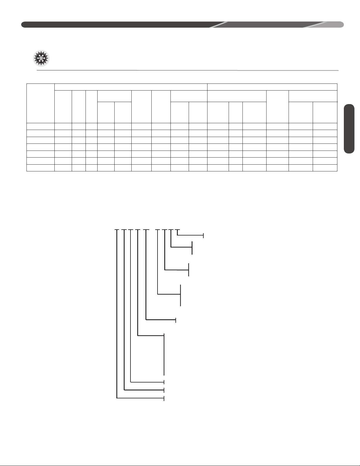
UNIT MODEL NUMBER EXPLANATION
R
24
A
14
AJ1NA
MINOR SERIES
TYPE
C - COMMUNICATING
N - NON-COMM
TYPE
1 - SINGLE STAGE
VOLTAGE
J= 1 PH, 208-230/60
C= 3 PH, 208-230/60
D= 3 PH, 460/60
MAJOR SERIES
CAPACITY
18 = 18,000 BTU/HR [5.28 kW]
24 = 24,000 BTU/HR [7.03 kW]
30 = 30,000 BTU/HR [8.79 kW]
36 = 36,000 BTU/HR [10.55 kW]
42 = 42,000 BTU/HR [12.31 kW]
48 = 48,000 BTU/HR [14.07 kW]
60 = 60,000 BTU/HR [17.58 kW]
SEER
HEAT PUMP
BRAND
5
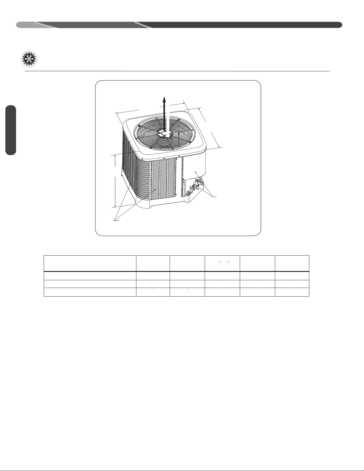
GENERAL INFORMATION
“ L”
“W”
“H”
A
I
R
D
I
S
C
H
A
R
G
E
ALLOW 60” [1524mm]
OF CLEARANCE
AIR INLET LOUVERS ALLOW
6” [152mm] Min. OF CLEARANCE ALL SIDES
12” [305mm] RECCOMMENDED
SERVICE PANELS/
INLET CONNECTIONS / HIGH & LOW
VOLTAGE ACCESS
ALLOW 24” [ 610 mm] OF CLEARANCE
ST-A1226-02-00
DIMENSIONAL DATA
Specifications
General Information
AIR INLET LOUVERS ALLOW
6" [152 mm] OF CLEARANCE ALL SIDES
12" [305 mm] RECOMMENDED
ALLOW 60" [1524mm] OF
CLEARANCE
SERVICE PANELS/
INLET CONNECTIONS /
HIGH & LOW VOLTAGE
ACCESS ALLOW
24" [610 mm] OF
CLEARANCE
CONDENSING UNIT MODEL
LENGTH “H” (INCHES)
LENGTH “L” (INCHES)
WIDTH “W” (INCHES)
Proper Installation
Proper sizing and installation of this equipment is
critical to achieve optimal performance� Use the
information in this Installation Instruction Manual
and reference the applicable manufacturer’s
specification sheet when installing this product�
IMPORTANT: This product has been
designed and manufactured to meet ENERGY
STAR criteria for energy efficiency when matched
with appropriate indoor components� However,
proper refrigerant charge and proper airflow are
critical to achieve rated capacity and efficiency�
Installation of this product should follow the
manufacturer’s refrigerant charging and airflow
instructions� Failure to confirm proper charge
and airflow may reduce energy efficiency and
shorten equipment life�
RA14
0
18, 24
25
19" 19" 29"23" 33"
29.75
351⁄2" 401⁄2" 443⁄8"443⁄8" 443⁄8"
29.75
243⁄4"
18
0
30
27
29.75
29.75
275⁄8"
36, 42
27
33.75
33.75
49043/037 060
48
31
33.75
33.75
311⁄2"311⁄2" 311⁄2"
35.75
35.75
MATCH ALL COMPONENTS:
• OUTDOOR UNIT
• INDOOR COIL
• INDOOR AIR HANDLER/FURNACE
• REFRIGERANT LINES
• INDOOR THERMOSTAT
60
35
6
Choosing a Location
INSTALLATION
IMPORTANT:
national building codes and ordinances for special
installation requirements� Following location
information will provide longer life and simplified
servicing of the outdoor unit�
Consult local and
NOTICE: These units must be installed
outdoors� No ductwork can be attached, or
other modifications made, to the discharge grille�
Modifications will affect performance or operation�
Operational Issues
IMPORTANT: Locate the unit
in a manner that will not prevent, impair, or
compromise the performance of other equipment
installed in proximity to the unit� Maintain all
required minimum distances to gas and electric
meters, dryer vents, and exhaust and inlet
openings� In the absence of national codes or
manufacturers’ recommendations, local code
recommendations and requirements will take
precedence�
• Refrigerant piping and wiring should be properly
sized and kept as short as possible to avoid
capacity losses and increased operating costs�
• Locate the unit where water runoff will not create
a problem with the equipment� Position the unit
away from the drip edge of the roof whenever
possible� Units are weatherized, but can be
affected by the following:
• Water pouring into the unit from the junction
of rooflines, without protective guttering�
Large volumes of water entering the unit while
in operation can impact fan blade or motor
life, and coil damage may occur if moisture
cannot drain from the unit under freezing
conditions�
• Closely follow the clearance recommendations
on page 8�
• 24" [61.0 cm] to the service panel access
• 60" [152.4 cm] above fan discharge (unit top)
to prevent recirculation
• 6" [15.2 cm] to coil grille air inlets
with 12" [30.5 cm] minimum recommended
Corrosive Environment
The metal parts of this unit may be subject to
rust or deterioration if exposed to a corrosive
environment� This oxidation could shorten the
equipment’s useful life�
Corrosive elements include, but are not limited to,
salt spray, fog or mist in seacoast areas, sulphur or
chlorine from lawn watering systems, and various
chemical contaminants from industries such as
paper mills and petroleum refineries�
If the unit is to be installed in an area where
contaminants are likely to be a problem, special
attention should be given to the equipment
location and exposure�
• Avoid having lawn sprinkler heads spray directly
on the unit cabinet�
• In coastal areas, locate the unit on the side of
the building away from the waterfront�
• Shielding provided by a fence or shrubs may
give some protection, but cannot violate
minimum airflow and service access clearances�
• Elevating the unit off its slab or base enough to
allow air circulation will help avoid holding water
against the base pan�
WARNING: Disconnect all power
to unit before starting maintenance� Failure to do
so can cause electrical shock resulting in severe
personal injury or death�
Regular maintenance will reduce the buildup of
contaminants and help to protect the unit’s finish�
• Frequent washing of the cabinet, fan blade, and
coil with fresh water will remove most of the salt
or other contaminants that build up on the unit�
• Regular cleaning and waxing of the cabinet with
a good automobile polish will provide some
protection�
• A good liquid cleaner may be used several times
a year to remove matter that will not wash off
with water�
Location
7
INSTALLATION
6” MIN. [152mm] FOR 1.5 & 2 TON
9”MIN [229mm] FOR 2.5 – 5 TON
24” [610mm]
SERVICE PANELS/INLET CONNECTIONS/
HIGH & LOW VOLTAGE ACCESS
ALLOW 24” [610 mm] OF CLEARANCE
ALLOW 60” [1524 mm]
OF CLEARANCE
AIR INLET LOUVERS ALLOW
6” [152 mm] Min. OF
CLEARANCE ALL SIDES
12” [305 mm] RECOMMENDED
ST-A1226-04-00
Choosing a Location (cont�)
Location
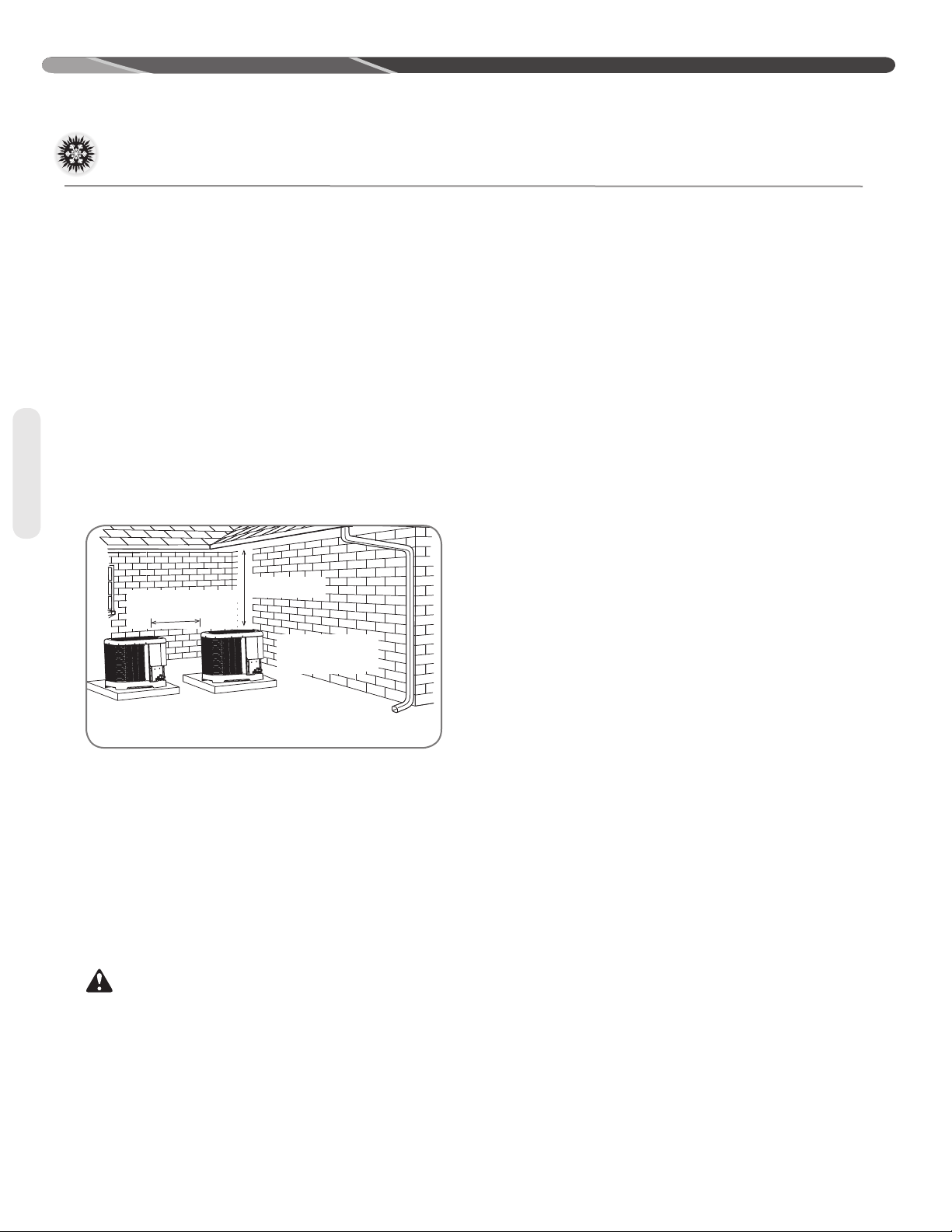
For Units With Space
Limitations
In the event that a space limitation exists, we will
permit the following clearances:
Single-Unit Applications: Side clearances below 6"
[15.2 cm] will reduce unit capacity and efficiency.
Do not reduce the 60" [152.4 cm] discharge or the
24" [61.0 cm] service clearances.
Multiple-Unit Applications: When multiple
condenser grille sides are aligned, a 6" [15.2
cm] clearance is recommended for 1.5 and 2
ton models and 9" [22.9 cm] for 2.5 ton to 5 ton
models� Two combined clearances below the
minimum will reduce capacity and efficiency� Do
not reduce the 60" [152.4 cm] discharge or 24"
[61.0 cm] service clearances.
• If installing a unit on a flat roof, use 4" x 4"
[10.2 cm x 10.2 cm] or equivalent stringers
positioned to distribute unit weight evenly and
prevent noise and vibration�
Factory-Preferred Tie-Down
Method for High Wind or
Seismic Loads
IMPORTANT: The manufacturer-
approved/recommended method is a guide to
securing equipment for wind and seismic loads�
Other methods might provide the same result, but
the manufacturer method is the only one endorsed
by the manufacturer for securing equipment where
wind or earthquake damage can occur� Additional
information is available in the PTS (Product
Technical Support) section of the manufacturer’s
Web sites MyRheem�com or MyRuud�com and
can be found as a listing under each outdoor
model� If you do not have access to this site, your
distributor can offer assistance�
Customer Satisfaction Issues
• The unit should be located away from the living,
sleeping, and recreational spaces of the owner
and those spaces on adjoining property�
• To prevent noise transmission, the mounting pad
for the outdoor unit should not be connected to
the structure and should be located a sufficient
distance above grade to prevent ground water
from entering the unit�
Unit Mounting
WARNING: Secure an elevated unit
and its elevating stand in order to prevent tipping�
Failure to do so may result in severe personal
injury or death�
8
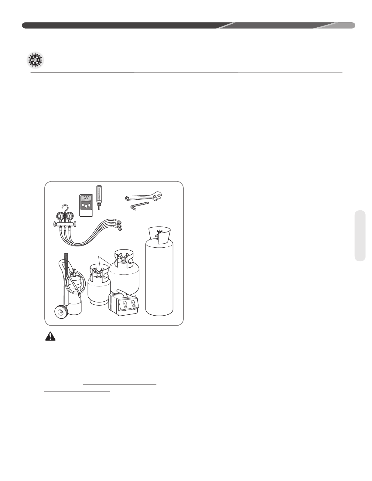
Tools and Refrigerant
Ambient and Tube
Thermometers
Manifold
Gauge
Set
Brazing
Rods
Torch Nitrogen
Reclaimer
Recovery
Cylinders
Allen Wrench
Crescent Wrench
INSTALLATION
Tools Required for Installing
and Servicing R-410A Models
Manifold Sets:
– Up to 800 PSIG High-Side
– Up to 250 PSIG Low-Side
– 550 PSIG Low-Side Retard
Manifold Hoses:
– Service Pressure Rating of 800 PSIG
Recovery Cylinders:
– 400 PSIG Pressure Rating
– Dept� of Transportation 4BA400 or BW400
CAUTION: R-410A systems operate
at higher pressures than R-22 systems� Do not
use R-22 service equipment or components on
R-410A equipment�
Specifications of R-410A
Application: R-410A is not a drop-in
replacement for R-22� Equipment designs must
accommodate its higher pressures� It cannot be
retrofitted into R-22 heat pumps�
Physical Properties: R-410A has an atmospheric
boiling point of -62.9°F [-52.7°C] and its saturation
pressure at 77°F [25°C] is 224.5 psig.
Composition: R-410A is a near-azeotropic
mixture of 50% by weight difluoromethane (HFC-
32) and 50% by weight pentafluoroethane (HFC-
125)�
Pressure: The pressure of R-410A is
approximately 60% (1�6 times) greater than
R-22� Recovery and recycle equipment, pumps,
hoses, and the like must have design pressure
ratings appropriate for R-410A� Manifold sets
need to range up to 800 psig high-side and 250
psig low-side with a 550 psig low-side retard.
Hoses need to have a service pressure rating of
800 psig. Recovery cylinders need to have a 400
psig service pressure rating, DOT 4BA400 or DOT
BW400.
Combustibility: At pressures above 1
atmosphere, a mixture of R-410A and air can
become combustible� R-410A and air should
never be mixed in tanks or supply lines or
be allowed to accumulate in storage tanks�
Leak checking should never be done with a
mixture of R-410A and air� Leak-checking can
be performed safely with nitrogen or a mixture of
R-410A and nitrogen�
Quick-Reference Guide For
R-410A
• R-410A refrigerant operates at approximately
60% higher pressure (1�6 times) than R-22�
Ensure that servicing equipment is designed to
operate with R-410A�
• R-410A refrigerant cylinders are light rose in
color�
• R-410A, as with other HFCs, is only compatible
with POE oils�
• Vacuum pumps will not remove moisture from
POE oil used in R-410A systems�
• R-410A systems are to be charged with liquid
refrigerants� Prior to March 1999, R-410A
refrigerant cylinders had a dip tube� These
cylinders should be kept upright for equipment
charging� Post-March 1999 cylinders do not
have a dip tube and should be inverted to ensure
liquid charging of the equipment�
• Do not install a suction line filter drier in the
liquid line�
• A factory-approved biflow liquid line filter drier
is shipped with every unit and must be installed
in the liquid line at the time of installation� Only
manufacturer-approved liquid line filter driers can
be used� These are Sporlan (CW083S) and Alco
(80K083S) driers� These filter driers are rated for
minimum working pressure of 600 psig� The filter
drier will only have adequate moisture-holding
capacity if the system is properly evacuated�
• Desiccant (drying agent) must be compatible for
POE oils and R-410A refrigerant�
Tools
9

INSTALLATION
Replacement Units
To prevent failure of a new unit, the existing line set
must be correctly sized and cleaned or replaced�
Care must be exercised that the expansion device
is not plugged� For new and replacement units, a
liquid line filter drier must be installed and refrigerant
tubing must be properly sized� Test the oil for acid� If
positive, a suction line filter drier is mandatory�
Indoor Coil
CAUTION: Only use evaporators
approved for use on R-410A systems that are
specifically matched with the outdoor unit per
the manufacturer’s specification sheets� Use
of existing R-22 evaporators can introduce
mineral oil to the R-410A refrigerant, forming two
different liquids and decreasing oil return to the
compressor� This can result in compressor failure�
REFER TO INDOOR COIL MANUFACTURER’S
INSTALLATION INSTRUCTIONS.
IMPORTANT: The manufacturer is not
responsible for the performance and operation of
a mismatched system or for a match listed with
another manufacturer’s coil�
IMPORTANT: When replacing an
R-22 unit with an R-410A unit, either replace
the line set or ensure that residual mineral oil is
drained from existing lines, including oil trapped in
low spots�
The thermostatic expansion valve in the
matching coil is specifically designed to operate
with R-410A� DO NOT use an R-22 TXV or
evaporator� The existing evaporator must
be replaced with the factory-specified TXV
evaporator specifically designed for R-410A�
Location
Do not install the indoor coil in the return duct
system of a gas or oil furnace� Provide a service
inlet to the coil for inspection and cleaning� Keep
the coil pitched toward the drain connection�
CAUTION: When coil is installed
over a finished ceiling and/or living area, it is
required that a secondary condensate pan be
installed under entire unit� Failure to do so can
result in property damage�
Tubing
10
Interconnecting Tubing
The purpose of this section is to specify the
best construction/sizing practices for installing
interconnection tubing between the indoor and
outdoor unit�
Refrigerant Level Adjustment
All units are factory-charged with R-410A
refrigerant to cover 15 feet of standard size
interconnecting liquid and vapor lines with a
required eld installed lter drier. Adjustment of
charge may be necessary even if the application
has exactly 15 feet of line set due to other
installation variables such as pressure drop,
vertical lift, and indoor coil size. For dierent
lengths, adjust the charge as indicated below�
adjust the charge as indicated below�
• 1/4” ± .3 oz./foot [6.4 mm ± 8.5 g/.30 m]
• 5/16” ± .4 oz./foot [7.9 mm ± 11.3 g/.30 m]
• 3/8” ± .6 oz./foot [9.5 mm ± 17.0 g/.30 m]
• 1/2” ± 1.2 oz./foot [12.7 mm ± 34.0 g/.30 m]
• 6 oz. Required factory supplied eld installed
• lter dry
Charge Adjustment = (Line Set (oz. /ft.) x Total
Length) – Factory Charge for Line Set
Example: A three ton condensing unit with factory
installed 3/8” liquid service valve
requires 75 ft of line set with a liquid line diameter
of 1/2”.
Factory Charge for Line Set = 15ft x �6 oz� = 9 oz�
Charge Adjustment = (1�2 oz� x 75 ft�) – 9 oz� =
+81 oz�
Interconnecting Tubing (cont�)
INSTALLATION
Interconnecting Tubing and
Fitting Losses
Refrigerant tubing is measured in terms of actual
length and equivalent length� Actual length is used
for refrigerant charge applications� Equivalent
length takes into account pressure losses from
Equivalent Length for Fings ()
90° Short
Line Size
(in)
3/8 1.3 0.8 0.3 6 4 0.4 6
1/2 1.4 0.9 0.4 9 5 0.6 6
5/8 1.5 1 0.5 12 6 0.8 6
3/4 1.9 1.3 0.6 14 7 0.9 6
7/8 2.3 1.5 0.7 15 8 1 6
1-1/8 2.7 1.8 0.9 22 12 1.5 6
Radius
Elbow
90° Long
Radius
Elbow
45°
Elbow
Liquid Line Selection
The purpose of the liquid line is to transport warm
sub-cooled liquid refrigerant from the outdoor unit
to the indoor unit� It is important not to allow the
refrigerant to ash any superheated vapor prior
to the expansion device of the indoor coil� The
ashing of refrigerant can occur for the following
reasons:
• Low refrigerant charge
• Improperly selected liquid line size
• Absorption of heat prior to expansion device
• Excessive vertical rise between the condenser
and evaporator
tubing length, ttings, vertical separation, accessories, and lter dryers. The table below references
dierent commonly used equivalent lengths.
Table 1
Solenoid
Valve
Table 2 lists the equivalent length per 25’ of liquid
line at various diameters up to 300’� The total pressure drop allowed for the liquid line is 50 PSI� The
procedure for selecting the proper liquid line is as
follows:
• Measure the total amount of vertical rise
• Measure the total amount of liquid line needed
• Add all of the equivalent lengths associated with
any ttings or accessories using the table above.
• Add the total length and tting pressure drop.
This will equal your total equivalent length�
• Reference Table 2 to verify the calculated
equivalent length is compatible with the required
vertical rise and diameter of liquid line�
Check
Valve
Site
Glass
Filter
Dryer
Tubing
Note: Elevaon is defined as the
highest point of the line set to the
lowest
11
INSTALLATION
Interconnecting Tubing (cont�)
Example: A 3-Ton condensing unit is installed 50’
below the ID unit, requires a 75’ of 1/2” diameter
liquid line, and 4 90° LR elbows�
• Fitting Equivalent Length (ft�) = 4 x �9 = 3�6’
• Total Equivalent Length (ft.) = 75’ + 3.6’ = 78.6’
Tubing
Liquid Line
R-410A
System
Capacity
Model
(excerpt fromTable 2, page 16)
Size
Connection
Size (Inch
I.D.) [mm]
37 3/8" [9.53]
Liquid Line
Size (Inch
O.D.) [mm]
1/4 [6.35] 25 [7.62]
5/16 [7.94] 25 [7.62] 50 [15.24] 60 [18.29] 45 [13.72] 35 [10.67] 20 [6.1] 5 [1.52]
3/8 [9.53] 25 [7.62] 50 [15.24] 75 [22.86] 80 [24.38] 80 [24.38] 75 [22.86] 70 [21.34] 65 [19.81] 60 [18.29] 55 [16.76] 50 [15.24] 45 [13.72]
7/16 [11.12] 25 [7.62] 50 [15.24] 75 [22.86] 95 [28.96] 90 [27.43] 90 [27.43] 85 [25.91] 85 [25.91] 85 [25.91] 80 [24.38] 80 [24.38] 80 [24.38]
1/2 [12.71] 25 [7.62] 50 [15.24] 75 [22.86] 95 [28.96] 95 [28.96] 95 [28.96] 95 [28.96] 95 [28.96] 95 [28.96] 90 [27.43] 90 [27.43] 90 [27.43]
25 [7.62] 50 [15.24] 75 [22.86] 100 [30.48] 125 [45.72] 150 [45.72] 175 [53.34] 200 [60.96] 225 [68.58] 250 [76.20] 275 [83.82] 300 [91.44]
N/R N/R N/R N/R N/R N/R N/R N/R N/R N/R N/R
This application is acceptable because the 50’
vertical rise is less than the maximum rise of 75’ for
this application� The application is also considered
to have a long line set� Reference the long line set
section of the I&O for detail�
Long Line Set Applications
Long line set applications are dened as applications that require accessories or alternate
construction methods� The following are special
considerations that need to be addressed when
installing a long line set application:
• Additional refrigerant charge
• Fitting losses and maximum equivalent length
considerations
• Refrigerant migration during the o cycle
• Oil return to the compressor
• Capacity losses
• System oil level adjustment
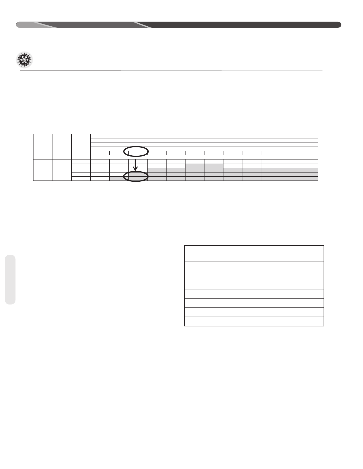
Table 2 is used to determine if the application is
considered to have a long line set� The region of
the chart that is shaded grey is considered to
be a long line set application.
Liquid Line Size
Elevation (Above or Below) Indoor Coil
Total
Maximum
Length - Feet [m]
Equivalent
Vertical Separation - Feet [m]
N/R N/R N/R N/R N/R
Oil Level Adjustments for
Long Line Set Applications
Additional oil will need to be added for long line set
applications� (Ref� Table 2)� Below is the equation
for the oil level adjustment and the compressor
name plate oil charge for the dierent od units.
OD Model
RP1518
RP1524
RP1530
RP1536
RP1542
RP1548
RP1560
Compressor
ZP16K5E-PFV-13R 21
ZP21K5E-PFV-13R 21
ZP25K5E-PFV-13R 25
ZP31K6E-PFV-130 21
ZP36K5E-PFV-13R 42
ZP40K6E-PFV-130 42
ZP49K6E-PFV-130 42
Oil to be Added = [(Charge Adjustment + OD
Unit Name Plate Charge (oz.)) x (0.022) – [(0.10)
x (Compressor Name Plate Oil Charge (oz.))]
Example: An application requires 125ft of line set
with a liquid line diameter of 3/8”, Charge Adjustment = 52�4 oz�, Name Plate Charge = 107 oz�,
Name Plate Oil Charge = 25 oz�, Oil to be Added =
((52�4 oz� +107 oz�) x �022) – (�10 x 25 oz�) = 1�0 oz�
Name Plate Oil
Charge (oz)
12
Interconnecting Tubing (cont�)
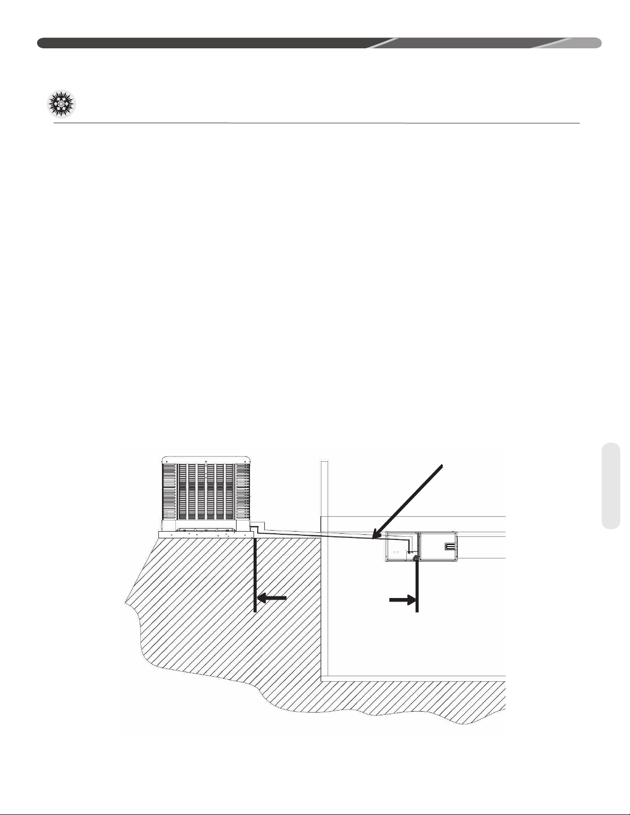
Outdoor and Indoor Same Level
INSTALLATION
Suction Line Selection
Purpose of the suction line is to return superheated
vapor to the condensing unit from the evaporator�
Proper suction line sizing is important because it
plays an important role in returning oil to the compressor to prevent potential damage to the bearings, valves, and scroll sets� Also, an improperly
sized suction line can dramatically reduce capacity
and performance of the system� The procedure for
selecting the proper suction line is as follows:
• The total amount of suction line needed
• Add all of the equivalent lengths associated with
any ttings or accessories using the table on
previous page�
• Add the total length and tting pressure drop.
This will equal your total equivalent length�
• Reference Table 2 to verify that the calculated
equivalent length falls within the compatibility
region of the chart�
• Verify Table 3 to verify the capacity dierence is
compatible with the application�
Refrigerant Migration During
Off Cycle
Long line set applications can require a considerable amount of additional refrigerant� This additional refrigerant needs to be managed throughout the
entire ambient operating envelope that the system
will go through during its life cycle. O-Cycle migration is where excess refrigerant condenses and
migrates to the lowest part of the system� Excessive build-up of refrigerant at the compressor will
result in poor reliability and noisy operation during
startup� This section demonstrates the required
accessories and unit conguration for dierent applications�
Ideally, line set slopes
away from outdoor.
Verify sub-cooling prior
to throling device,
Insulated liquid line
Tubing
Reference Table 2 for
maximum length
limitaons
Figure 3
13
INSTALLATION
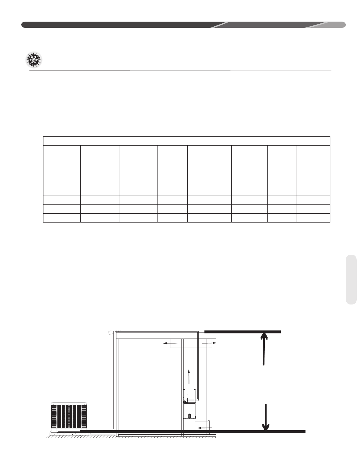
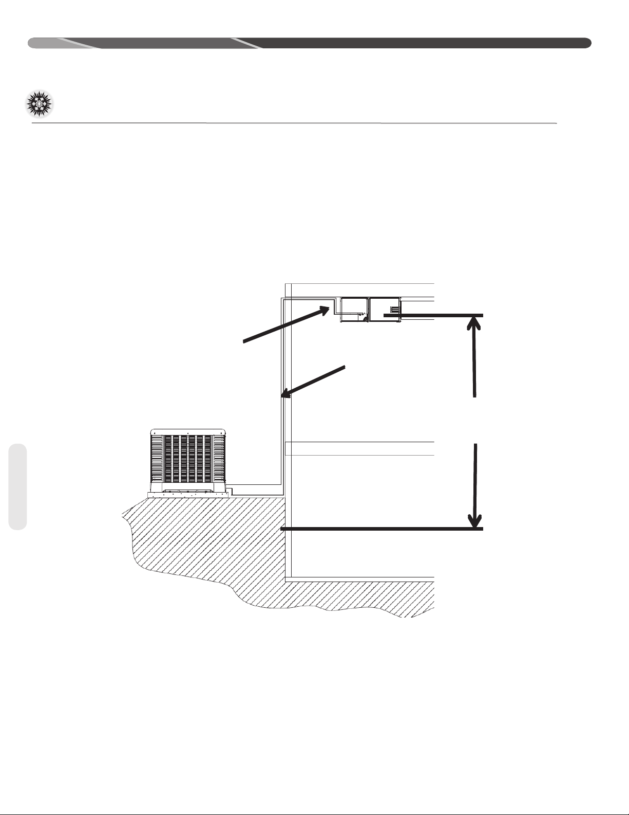
Indoor Unit Above Outdoor Coil
Interconnecting Tubing (cont�)
For applications that are considered to have a long
line set with the outdoor unit and indoor unit on the
same level the following is required:
• TXV or EEV on the indoor unit
• Start components may be required depending
upon quality of voltage
• Crankcase heater
• Insulated liquid and suction line
Inverted trap even with
top of the coil
• Vapor line should slope toward the indoor unit
• Follow the proper line sizing, equivalent length,
charging requirements, and oil level adjustments
spelled out in this document and the outdoor
units I&O
• Verify adequate sub-cooling at the ID unit prior
to throttling device
Insulated liquid and
sucon line
Reference Table 2
for elevaon
limitaons
Tubing
For applications that are considered to have a long
line set with the outdoor unit below the indoor unit
the following is required:
• TXV or EEV at the IDunit
• Crankcase heater
• Start components may be required depending
upon quality of voltage
• Inverted vapor-line trap (Reference Figure 3)
• Insulated liquid and suction line
Figure 4
• Follow the proper line sizing, equivalent length,
charging requirements, and oil level adjustments
spelled out in this document and the outdoor
units I&O
• Measure pressure at the liquid line service valve
and prior to expansion device� Verify that it is
not greater than 50 PSI
• For elevations greater that 25’ can expect a
lower sub-cooling
14
 Loading...