

Page 1
WARNING:
hry r
dly
r
RECOGNIZE THIS SYMBOL
AS AN INDICATION OF
IMPORTANT SAFETY
INFORMATION
WARNING
THESE INSTRUCTIONS
ARE INTENDED AS AN AID
TO QUALIFIED, LICENSED
SERVICE PERSONNEL FOR
PROPER INSTALLATION,
ADJUSTMENT, AND
OPERATION OF THIS
UNIT. READ THESE
INSTRUCTIONS
THOROUGHLY
BEFORE ATTEMPTING
INSTALLATION OR
OPERATION. FAILURE
TO FOLLOW THESE
INSTRUCTIONS MAY
RESULT IN IMPROPER
INSTALLATION,
ADJUSTMENT, SERVICE,
OR MAINTENANCE
POSSIBLY RESULTING IN
FIRE, ELECTRICAL SHOCK,
PROPERTY DAMAGE,
PERSONAL INJURY, OR
DEATH.
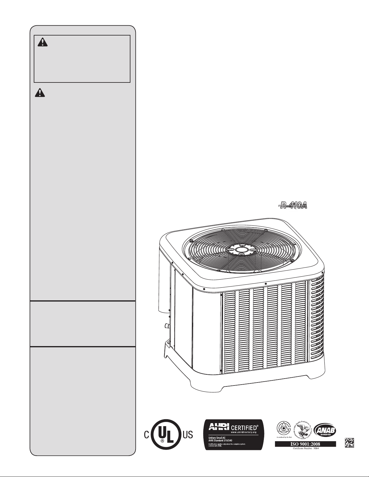
AIR COOLED
CONDENSING UNITS
INSTALLATION INSTRUCTIONS
RA13, RA14 & RA16 MODEL SERIES –
13, 14 & 16 SEER
FEATURING INDUSTRY STANDARD
R-410A REFRIGERANT
earth friendly refrigeranteart
n
f
Do not destroy this manual.
Please read carefully
and keep in a safe place
for future reference by a
serviceman.
[ ] indicates metric conversions.
92-104921-09-04 (10/15)
Printed in USA
Page 2

CONTENTS
Important
Safety Information ............................................. 3
General Information ........................................4-7
Checking Product Received ........................................4
Contents
Application ...................................................................4
Electrical and Physical Data ..................................... 5-6
Unit Model Number ......................................................6
Dimensional Data .........................................................6
Specifications ...............................................................7
Proper Installation ........................................................7
Installation .................................................... 8-25
Choosing a Location ........................................8-9
Operational Issues........................................................8
Corrosive Environment .................................................8
For Units With
Space Limitations .........................................................9
Customer Satisfaction Issues ......................................9
Unit Mounting ............................................................... 9
Factory-Preferred
Tie-Down Method.........................................................9
Tools and Refrigerant ...................................... 10
Tools Required for Installing and
Servicing R-410A Models ..........................................10
Specifications of R-410A ...........................................10
Quick-Reference
Guide for R-410A ....................................................... 10
Replacement Units ...........................................11
Indoor Coil ........................................................11
Location ...................................................................... 11
Interconnecting Tubing ................................ 11-25
Refrigerant Level Adjustment .....................................11
Fitting Losses .............................................................12
Liquid Line Selection ..................................................12
Long Line Set Applications ........................................13
Oil Level Adjustments ................................................13
Suction Line Selection ...............................................14
Refrigerant Migration ..................................................14
Installation ............................................................ 17-22
Tubing Installation ......................................................23
Tubing Connections ...................................................24
Leak Testing ...............................................................25
Wiring .........................................................26-27
Control Wiring ............................................................26
Thermostat Wiring Diagrams .....................................26
Power Wiring ..............................................................27
Grounding ................................................................... 27
Start-Up ......................................................28–32
Start-Up ......................................................................28
Checking Airflow ........................................................28
Evacuation Procedure ............................................... 29
Final Leak Testing .......................................................29
Checking
Refrigerant Charge ...................................... 30-32
Charging Units
With R-410A Refrigerant ............................................ 30
Confirm ID Airflow
and Coils Are Clean ...................................................30
Measurement Device Setup .......................................30
Charging by Weight ....................................................30
Gross Charging by Pressures ....................................31
Final Charge by Subcooling .......................................31
Finishing Up Installation .............................................32
Components and Controls ..........................33-34
Compressor
Crankcase Heat (CCH) ......................................33
High- and Low-Pressure
Controls (HPC and LPC) ....................................33
Hard-Start Components ....................................34
Accessories ..................................................... 34
Single Pole Compressor
Contactor (CC) ........................................................... 34
Time-Delay Control ....................................................34
Hard Start Components ............................................. 34
Low Ambient Control (LAC) .......................................34
Hard Start Components ................................... 34
Diagnostics ................................................. 35-43
Electrical Checks Flowchart ....................................... 35
Cooling Mechanical
Checks Flowchart ......................................................36
General Troubleshooting Chart ....... ...........................37
Service Analyzer Charts ....................................... 38-42
Cooling Troubleshooting Tips ....................................43
Wiring Diagrams ......................................... 44-45
2
Page 3
IMPORTANT SAFETY INFORMATION
WARNINGS:
• These instructions are intended as an aid to
qualified, licensed service personnel for proper
installation, adjustment, and operation of this
unit. Read these instructions thoroughly before
attempting installation or operation. Failure to
follow these instructions may result in improper
installation, adjustment, service, or maintenance
possibly resulting in fire, electrical shock,
property damage, personal injury, or death.
• The unit must be permanently grounded. Failure
to do so can cause electrical shock resulting in
severe personal injury or death.
• Turn off electric power at the fuse box or service
panel before making any electrical connections.
• Complete the ground connection before making
line voltage connections. Failure to do so can
result in electrical shock, severe personal injury,
or death.
• Disconnect all power to unit before starting
maintenance. Failure to do so can cause
electrical shock resulting in severe personal
injury or death.
• Never assume the unit is properly wired and/or
grounded. Always test the unit cabinet with a
noncontact voltage detector available at most
electrical supply houses or home centers before
removing access panels or coming into contact
with the unit cabinet.
• Do not use oxygen to purge lines or pressurize
system for leak test. Oxygen reacts violently with
oil, which can cause an explosion resulting in
severe personal injury or death.
• The top of the scroll compressor shell is hot.
Touching the compressor top may result in serious
personal injury.
• The manufacturer’s warranty does not cover
any damage or defect to the unit caused by the
attachment or use of any components, accessories,
or devices (other than those authorized by the
manufacturer) into, onto, or in conjunction with
the heat pump. You should be aware that the
use of unauthorized components, accessories,
or devices may adversely affect the operation
of the heat pump and may also endanger life
and property. The manufacturer disclaims any
responsibility for such loss or injury resulting
from the use of such unauthorized components,
accessories, or devices.
CAUTIONS:
• R-410A systems operate at approximately 60%
higher pressures (1.6 times) than R-22 systems. Do
not use R-22 service equipment or components on
R-410A equipment. Use appropriate care when using
this refrigerant. Failure to exercise care may result in
equipment damage or personal injury.
• Only match this outdoor unit with a matched indoor
coil or air handler approved for use with this outdoor
unit per the unit manufacturer’s specification sheet.
The use of unmatched coils or air handler will likely
result in a charge imbalance between the cooling
and heating modes which can cause unsatisfactory
operation including a high-pressure switch lockout
condition.
• Only use indoor coils approved for use on R-410A
systems. An R-22 coil will have a TXV or fixed
restrictor device that is not designed to operate
properly in an R-410A system and will result in
serious operational issues. The R-22 coil could also
contain mineral oil which is incompatible with the
POE oil used in R-410A systems and could result in
reliability issues with the compressor and TXVs.
• When coil is installed over a finished ceiling and/or
living area, it is required that a secondary sheet metal
condensate pan be constructed and installed under
the entire unit. Failure to do so can result in property
damage.
• The compressor has an internal overload protector.
Under some conditions, it can take up to 2 hours for
this overload to reset. Make sure overload has had
time to reset before condemning the compressor.
Safety
3
Page 4

GENERAL INFORMATION
WARNING:
Improper installation, or installation not made in
accordance with these instructions, can result
in unsatisfactory operation and/or dangerous
conditions and can cause the related warranty
not to apply.
The condensing unit is designed to operate with
standard 24 VAC thermostats and air handlers or
gas furnaces.
This installation instruction manual contains
complete instructions for installation and setup
General Information
using conventional 24 VAC controls. Please refer
to the manufacturer’s specification sheets for
complete performance data, thermostat, and
accessory listings.
The information contained in this manual has
been prepared to assist in the proper installation,
operation, and maintenance of the air conditioning
system.
Read this manual and any instructions packaged
with separate equipment required to make up the
system prior to installation. Homeowner should
retain this manual for future reference.
To achieve optimum efficiency and capacity,
the matching indoor cooling coils listed in the
manufacturer’s specification sheet should be used.
Checking Product Received
Upon receiving unit, inspect it for any shipping
damage. Claims for damage, either apparent or
concealed, should be filed immediately with the
shipping company. Check model number, electrical
characteristics, and accessories to determine if they
are correct. Check system components (indoor coil,
outdoor unit, air handler/furnace, etc.) to make sure
they are properly matched.
Application
Before specifying any air conditioning equipment,
a survey of the structure and a heat gain
calculation must be made. A cooling heat gain
calculation determines the amount of heat needed
to be removed. A heat gain calculation also
calculates the extra heat load caused by sunlight
and by humidity removal. These factors must be
considered before selecting an air conditioning
system to provide year-round comfort. The Air
Conditioning Contractors of America (ACCA)
J Manual method of load calculation is one
recognized procedure for determining the heating
and cooling load.
After the proper equipment combination has
been selected, satisfying both sensible and
latent requirements, the system must be properly
installed. Only then can the unit provide the
comfort it was designed to provide.
There are several factors that installers must
consider.
• Outdoor unit location
• Indoor unit blower speed and airflow
• Proper equipment evacuation
• Supply and return air duct design and sizing
• Refrigerant charge
• System air balancing
• Diffuser and return air grille location and sizing
4
Page 5
Model
Number
RA1318AJ1NA
RA1324AJ1NA
RA1330AJ1NA
RA1336AJ1NA
RA1342AJ1NA
RA1348AJ1NA
RA1360AJ1NA
RA1336AC1NB
RA1342AC1NB
RA1348AC1NB
RA1360AC1NB
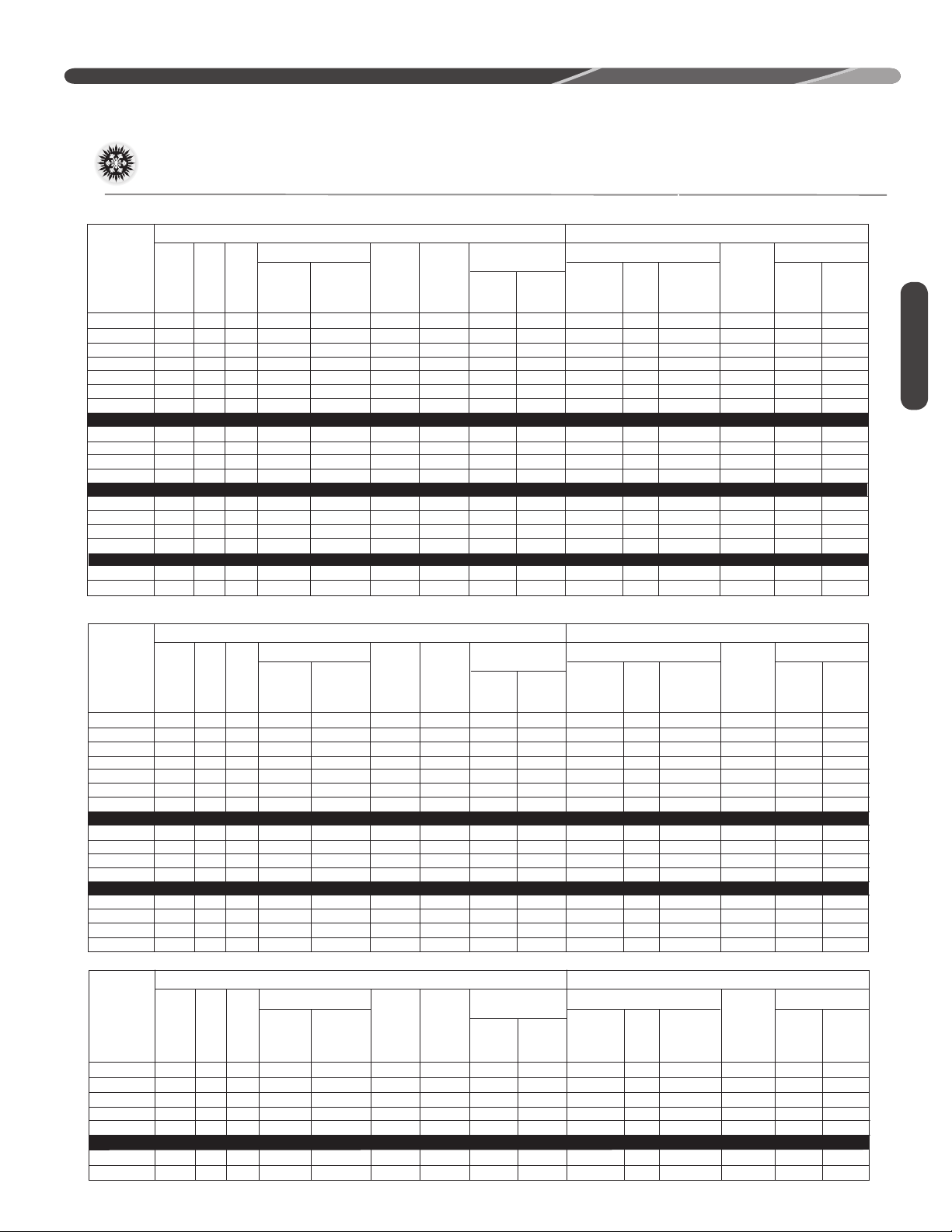
Electrical and Physical Data
RA13
ELECTRICAL PHYSICAL
Fuse or HACR
Circuit Breaker
20/20
20/20
25/25
25/25
30/30
35/35
45/45
20/20
25/25
25/25
30/30
Maximum
20/20
25/25
30/30
35/35
40/40
50/50
60/60
20/20
30/30
30/30
35/35
Minimum
Amperes Amperes
Voltage
208-230
208-230
208-230
208-230
208-230
208-230
208-230
208-230
208-230
208-230
208-230
Phase
1
Fan
Minimum
Rated Load
Freq
Amperes
60
1
60
1
60
1
60
1
60
1
60
1
60
3
60
3
60
3
60
3
60
(RLA)
9.7/9.7
11.2/11.2
12.8/12.8
15.4/15.4
17.9/17.9
21.8/21.8
26.4/26.4
10.4/10.4
13.2/13.2
13.7/13.7
16/16
Locked Rotor
Amperes
(LRA)
48.0
60.8
64.0
83.9
112.0
117.0
134.0
73.0
88.0
83.1
110.0
Motor
Amperes
(FLA)
Circuit
Full
Load
Ampacity
Amperes
13/13
0.70
15/15
0.70
18/18
1.30
21/21
1.30
24/24
0.70
29/29
1.00
35/35
1.20
15/15
1.30
18/18
1.30
19/19
1.00
11/11
1.30
GENERAL INFORMATION
Face
Area
Sq. Ft .
2
]
[m
5.9 [0.55]
9.06 [0.84]
9.06 [0.84]
12.15 [1.13]
14.18 [1.32]
14.82 [1.38]
18.84 [1.75]
12.15 [1.13]
14.18 [1.32]
14.82 [1.38]
18.84 [1.75]
Outdoor Coil WeightCompressor
Rows
1
No.
1
1
1
1
1
1
1
1
1
1
CFM
[L/s]
2038 [962]
2325 [1097]
2796 [1320]
2898 [1368]
2466 [1164]
4144 [1953]
3868 [1825]
2898 [1368]
2466 [1164]
4144 [1955]
3868 [1825]
Refrig .
Per
Circuit
(oz.)
[g]
50 [1417]
60 [1701]
72 [2041]
92 [2608]
105 [2977]
106 [3005]
148 [4196]
92 [2608]
105 [2977]
106 [3005]
148 [4195]
Net
Lbs.
[kg]
120 [54.4]
135 [61.2]
156 [70.8]
157 [71.2]
188 [85.3]
195 [88.4]
228 [103.4]
157 [71.2]
188 [85.3]
195 [88.4]
228 [103.4]
Shipping
Lbs. [kg]
127 [57.6]
142 [64.4]
163 [73.9]
164 [74.4]
195 [88.5]
202 [91.6]
235 [106.6]
164 [74.4]
195 [88.5]
202 [91.6]]
235 [106.6]
General Information
RA1336AD1NB
RA1342AD1NB
RA1348AD1NB
RA1360AD1NB
RA1348AY1NB
RA1360AYINB
Model
Number
RA1418AJ1NA
RA1424AJ1NA
RA1430AJ1NA
RA1436AJ1NA
RA1442AJ1NA
RA1448AJ1NA
RA1460AJ1NA
RA1436AC1NB
RA1442AC1NB
RA1448AC1NB
RA1460AC1NB
RA1436AD1NB
RA1442AD1NB
RA1448AD1NB
RA1460AD1NB
460
460
460
460
575
575
Voltage
208-230
208-230
208-230
208-230
208-230
208-230
208-230
208-230
208-230
208-230
208-230
460
460
460
460
Phase
1
3
60
3
3
3
3
3
5.8/5.8
60
6.0/6.0
60
6.2/6.2
60
7.8/7.8
60
4.8/4.8
60
5.7/5.7
38.0
44.0
41.0
52.0
33.0
38.9
0.50
0.30
0.50
0.60
1.00
0.50
8/8
8/8
9/9
11/11
8/8
8/8
15/15
15/15
15/15
15/15
15/15
15/15
15/15
15/15
15/15
15/15
15/15
15/15
12.15 [1.13]
14.18 [1.32]
14.82 [1.38]
18.84 [1.75]
14.82 [1.38]
18.84 [1.75]
1
1
1
1
1
1
2898 [1368]
2466 [1164]
4144 [1955]
3868 [1825]
4144 [1955]
3868 [1825]
92 [2608]
105 [2977]
106 [3005]
148 [4195]
106 [3005]
148 [4195]
157 [71.2]
188 [85.3]
195 [88.4]
228 [103.4]
195 [88.4]
228 [103.4]
164 [74.4]
195 [88.5]
202 [91.6]
235 [106.6]
202 [91.6]
235 [106.6]
RA14
ELECTRICAL PHYSICAL
Fan
Minimum
Rated Load
Freq
Amperes
60
1
60
1
60
1
60
1
60
1
60
1
60
3
60
3
60
3
60
3
60
3
60
3
60
3
60
3
60
(RLA)
9.7/9.7
11.2/11.2
12.8/12.8
14.1/14.1
17.9/17.9
19.9/19.9
23.7/23.7
9.0/9.0
13.2/13.2
13.1/13.1
15.9/15.9
5.6/5.6
6.0/6.0
6.1/6.1
7.1/7.1
Locked Rotor
Amperes
(LRA)
48.0
60.8
64.0
77.0
112.0
109.0
152.5
71.0
88.0
83.1
110.0
38.0
44.0
41.0
52.0
Motor
Amperes
Circuit
Full
Load
Ampacity
Amperes
(FLA)
13/13
0.60
15/15
0.70
17/17
0.70
19/19
0.60
24/24
1.20
26/26
1.00
31/31
1.00
12/12
0.60
18/18
1.20
18/18
1.00
21/21
1.00
0.50
0.60
0.60
0.50
8/8
9/9
9/9
10/10
Fuse or HACR
Circuit Breaker
Minimum
20/20
20/20
20/20
25/25
30/30
35/35
40/40
15/15
25/25
25/25
25/25
15/15
15/15
15/15
15/15
Maximum
20/20
25/25
25/25
30/30
40/40
45/45
50/50
20/20
30/30
30/30
35/35
15/15
15/15
15/15
15/15
Amperes Amperes
Face
Area
Sq. Ft .
2
]
[m
9.06 [0.84]
11.14 [1.03]
12.15 [1.13]
14.82 [1.38]
16.15 [1.5]
18.84 [1.75]
21.54 [2.00]
14.82 [1.38]
16.15 [1.5]
18.84 [1.75]
21.54 [2.00]
14.82 [1.38]
16.15 [1.5]
18.84 [1.75]
21.54 [2.00]
Outdoor Coil WeightCompressor
Rows
1
No.
Refrig .
Per
CFM
[L/s]
2225 [1050]
1
2505 [1182]
1
2605 [1229]
1
3104 [1464]
1
3954 [1866]
1
4264 [2012]
1
4139 [1953]
1
3104 [1464]
1
3954 [1866]
1
4264 [2012]
1
4139 [1953]
1
3104 [1464]
1
3954 [1866]
1
4264 [2012]
1
4139 [1953]
Circuit
(oz.)
[g]
68 [1928]
72 [2041]
87 [2466]
106 [3005]
119 [3374]
129 [3657]
162 [4593]
106 [3005]
119 [3374]
129 [3657]
162 [4593]
106 [3005]
119 [3374]
129 [3657]
162 [4593]
Net
Lbs.
[kg]
140 [63.5]
141 [64.0]
151 [68.5]
171 [77.6]
207 [93.9]
221 [100.2]
240 [108]
171 [77.6]
207 [93.9]
221 [100.2]
240 [108]
171 [77.6]
207 [93.9]
221 [100.2]
240 [108]
Shipping
Lbs. [kg]
147 [66.7]
148 [67.1]
158 [71.7]
178 [80.7]
214 [97.1]
228 [103.4]
247 [112]
178 [80.7]
214 [97.1]
228 [103.4]
247 [112]
178 [80.7]
214 [97.1]
228 [103.4]
247 [112]
Model
Number
RA1418WJ1NA
RA1424WJ1NA
RA1430WJ1NA
RA1436WJ1NA
RA1442WJ1NA
RA1436WC1NB
RA1442WC1NB
Voltage
208-230
208-230
208-230
208-230
208-230
208-230
208-230
208-230
Phase
1
ELECTRICAL PHYSICAL
Fan
Minimum
Rated Load
Freq
Amperes
60
1
60
1
60
1
60
1
60
1
60
3
60
3
60
(RLA)
9.7/9.7
10.9/10.9
12.8/12.8
15.4/15.4
16.7/16.7
19.9/19.9
10.4/10.4
11.2/11.2
Locked Rotor
Amperes
(LRA)
46
62.9
67.8
83.9
109
73
84
Amperes
(FLA)
Motor
Circuit
Full
Load
Ampacity
Amperes
13/13
0.60
15/15
0.75
17/17
0.75
21/21
0.8
23/23
1.2
26/26
1.00
14/14
0.8
16/16
1.2
Fuse or HACR
Circuit Breaker
Minimum
Maximum
Amperes Amperes
20/20
20/20
20/20
25/25
30/30
35/35
20/20
20/20
20/20
25/25
25/25
35/35
35/35
45/45
20/20
25/25
Face
Area
Sq. Ft .
2
]
[m
9.89 [0.92]
11.14 [1.04]
14.18 [1.32]
17.29 [1.61]
19.76 [1.84]
18.84 [1.75]
17.29 [1.61]
19.76 [1.84]]
Outdoor Coil WeightCompressor
Rows
1
No.
1
1
1
1
1
1
1
CFM
[L/s]
2322 [1096]
2295 [1083]
2594 [1224]
3393 [1601]
4103 [1936]
4264 [2012]
3393 [1601]
4103 [1936]
Refrig .
Per
Circuit
(oz.)
[g]
78.4 [2223]
80 [2268]
104 [2948]
103.2 [2926]
133.6 [3788]
129 [3657]
103.2 [2926]
133.6 [3788]
Net
Lbs.
[kg]
145 [65.8]
141 [64.0]
160 [72.6]
180 [81.6]
200 [90.7]
221 [100.2]
180 [81.6]
200 [90.7]
Shipping
Lbs. [kg]
152 [69.0]
148 [67.1]
167 [75.8]
187 [84.8]
207 [93.9]
228 [103.4]
187 [84.8]
207 [93.9]
5
Page 6
Minimum
Model
Number
Voltage
Phase
Freq
Rated Load
Amperes
(RLA)
Locked Rotor
Amperes
(LRA)
Fan
Motor
Full
Load
Amperes
(FLA)
Minimum
Circuit
Ampacity
Amperes
Maximum
Amperes Amperes
Face
Area
Sq. Ft .
[m
2
]
No.
Rows
CFM
[L/s]
Refrig .
Per
Circuit
(oz.)
[g]
Net
Lbs.
[kg]
Shipping
Lbs. [kg]
Fuse or HACR
Circuit Breaker
Outdoor Coil WeightCompressor
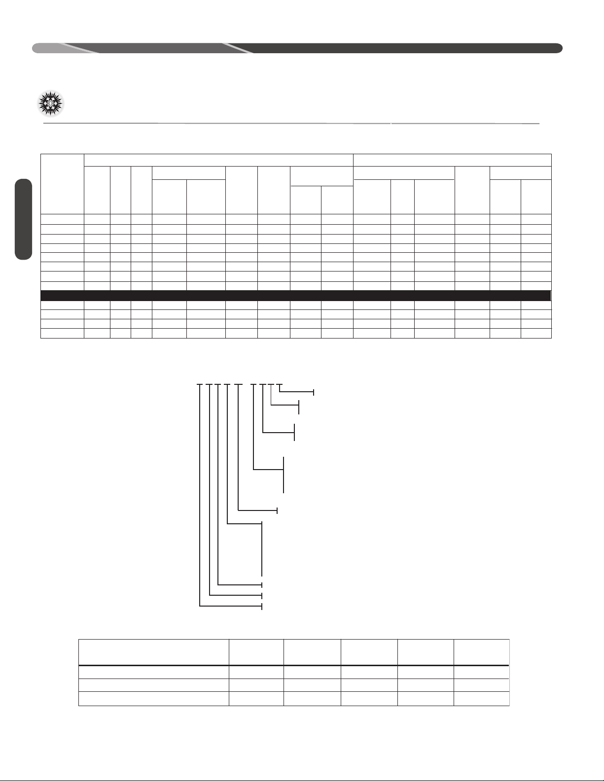
ELECTRICAL PHYSICAL
RA1618AJ1NA
RA1624AJ1NA
RA1630AJ1NA
RA1636AJ1NA
RA1642AJ1NA
RA1648AJ1NA
RA1660AJ1NA
RA1660BJ1NA
RA1636AC1NB
RA1642AC1NB
RA1648AC1NB
RA1660AC1NB
208-230
208-230
208-230
208-230
208-230
208-230
208-230
208-230
208-230
208-230
208-230
208-230
1
1
1
1
1
1
1
1
3
3
3
3
60
60
60
60
60
60
60
60
60
60
60
60
9.0/9.0
10.3/10.3
12.8/12.8
15.4/15.4
16.7/16.7
17.0/17.0
23.7/23.7
23.7/23.7
10.4/10.4
11.2/11.2
13.6/13.6
15.9/15.9
47.5
61.6
67.3
83.9
109.0
123.9
152.5
152.5
73
88
83.1
110
12/12
14/14
18/18
23/23
25/25
25/25
34/34
34/34
17/17
18/18
21/21
24/24
15/15
20/20
25/25
30/30
30/30
30/30
40/40
40/40
20/20
25/25
25/25
30/30
12.15 [1.13]
14.82 [1.38]
16.15 [1.50]
18.85 [1.75]
24.23 [2.25]
28.27 [2.63]
32.31 [3.00]
60.58 [5.63]
18.85 [1.75]
24.23 [2.25]
28.27 [2.63]
32.31 [3.00]
1
1
1
1
1
1
1
2
1
1
1
1
2404 [1134]
2851 [1345]
3914 [1847]
4340 [2048]
4450 [2100]
4658 [2198]
4776 [2254]
5124 [2418]
4340 [2048]
4450 [2100]
4658 [2198]
4776 [2254]
82 [2325]
87 [2466]
113 [3203]
108 [108]
150 [4252]
174 [4933]
201 [5698]
308 [8732]
108 [3062]
150 [4252]
174 [4933]
201 [5898]
148 [67.1]
163 [73.9]
188 [85.3]
200 [90.7]
246 [111.6]
261 [118.4]
289 [131.1]
300 [136]
200 [90.7]
246 [111.6]
261 [118.4]
289 [131.1]
155 [70.3]
170 [77.1]
195 [88.4]
207 [93.9]
253 [114.8]
268 [121.6]
296 [134.3]
307 [139.2]
207 [93.9]
253 [114.8]
268 [121.6]
296 [134.3]
0.70
0.60
1.40
3.50
3.50
3.50
3.50
3.50
3.50
3.50
3.50
3.50
20/20
20/20
30/30
35/35
40/40
40/40
50/50
50/50
25/25
25/25
30/30
35/35
GENERAL INFORMATION
Electrical and Physical Data - cont.
General Information
UNIT MODEL NUMBER EXPLANATION
A
R
13
24
AJ1NA
RA16
TYPE
N - NON-COMM
MINOR SERIES
DIMENSIONAL DATA
Height “H” inches [mm]
Length “L” inches [mm]
Width “W” inches [mm]
RA13
TYPE
1 - SINGLE STAGE
VOLTAGE
J = 1 PH, 208-230/60
C = 3 PH, 208-230/60
D = 3 PH, 460/60
Y = 3 PH, 575/60
MAJOR SERIES
CAPACITY
18 = 18,000 BTU/HR [5.28 kW]
24 = 24,000 BTU/HR [7.03 kW]
30 = 30,000 BTU/HR [8.79 kW]
36 = 36,000 BTU/HR [10.55 kW]
42 = 42,000 BTU/HR [12.31 kW]
48 = 48,000 BTU/HR [14.07 kW]
60 = 60,000 BTU/HR [17.58 kW]
SEER
CONDENSER
BRAND
18, 36 24, 30 42 48 60
27 [686] 25 [635] 27 [686] 27 [686] 31 [787]
29.75 [756] 29.75 [756] 33.75 [857] 33.75 [857] 35.75 [908]
29.75 [756] 29.75 [756] 29.75 [756] 33.75 [857] 33.75 [857]
6
Page 7
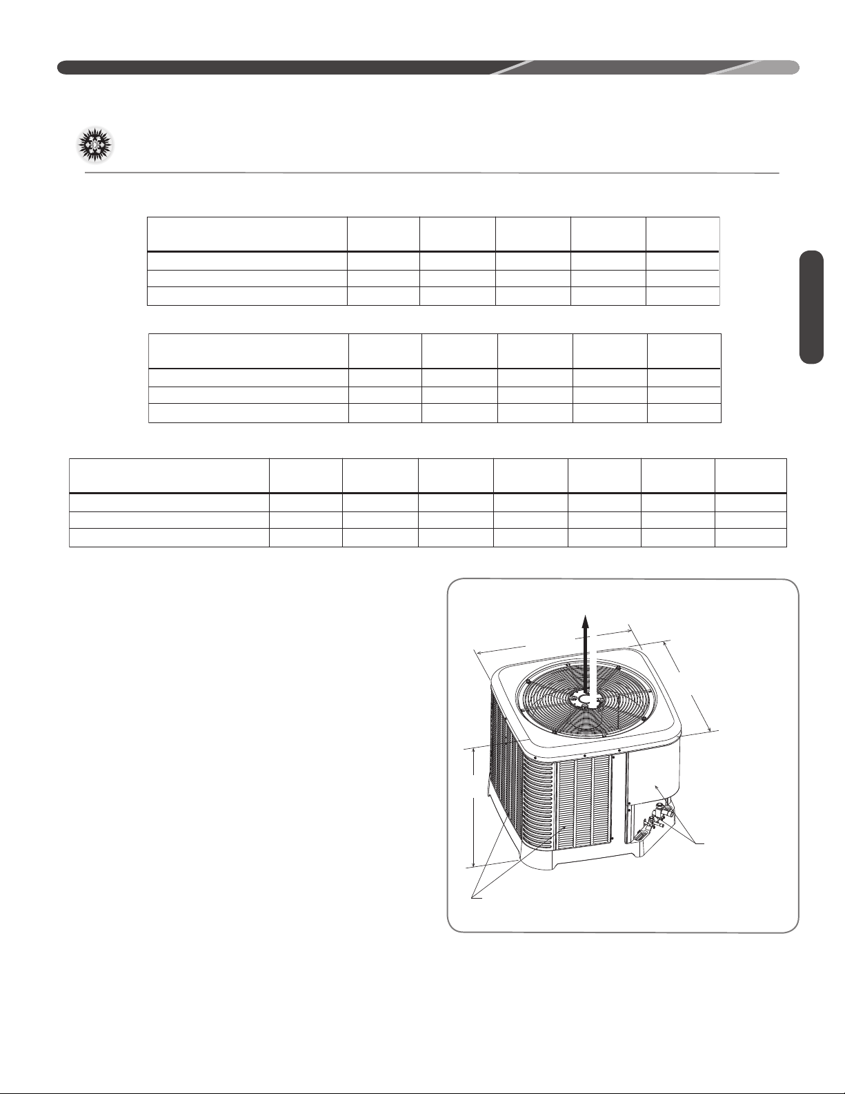
Specifi cations
“L”
“W”
“H”
A
I
R
D
I
S
C
H
A
R
G
E
ALLOW 60” [1524mm]
OF CLEARANCE
ST-A1226-02-00
GENERAL INFORMATION
Height “H” inches [mm]
Length “L” inches [mm]
Width “W” inches [mm]
Height “H” inches [mm]
Length “L” inches [mm]
Width “W” inches [mm]
RA16
Height “H” inches [mm]
Length “L” inches [mm]
Width “W” inches [mm]
RA14
RA14XXW
18 24 30 36 42 48 60
27 [686] 27 [686] 27 [686) 31 [787] 39 [991] 45 [1143] 51 [1295]
29.75 [756] 33.75 [857) 35.75 [908] 35.75 [908] 35.75 [908] 35.75 [908] 35.75 [908]
29.75 [756] 33.75 [857] 35.75 [908) 35.75 [908] 35.75 [908] 35.75 [908] 35.75 [908]
18, 24 30 36, 42 48 60
25 [635] 27 [686] 27 [686) 31 [787] 31 [787]
29.75 [756] 29.75 [756] 33.75 [857] 33.75 [857] 35.75 [908]
29.75 [756] 29.75 [756] 33.75 [857] 33.75 [857] 35.75 [908]
18 24 30 36 42
27 [686] 25 [635] 31 [787] 31 [787] 35 [889]
29.75 [756] 29.75 [756] 29.75 [756] 33.75 [857] 33.75 [857]
29.75 [756] 29.75 [756] 29.75 [756] 33.75 [857] 33.75 [857]
Proper Installation
Proper sizing and installation of this equipment is
critical to achieve optimal performance. Use the
information in this Installation Instruction Manual
and reference the applicable manufacturer’s
specification sheet when installing this product.
General Information
ALLOW 60" [1524mm] OF
CLEARANCE
IMPORTANT: This product has been
designed and manufactured to meet ENERGY
STAR criteria for energy efficiency when matched
with appropriate indoor components. However,
proper refrigerant charge and proper airflow are
critical to achieve rated capacity and efficiency.
Installation of this product should follow the
manufacturer’s refrigerant charging and airflow
instructions. Failure to confirm proper charge
and airflow may reduce energy efficiency and
shorten equipment life.
MATCH ALL COMPONENTS:
• OUTDOOR UNIT
• INDOOR COIL
• INDOOR AIR HANDLER/FURNACE
• REFRIGERANT LINES
• INDOOR THERMOSTAT
AIR INLET LOUVERS ALLOW
6" [152 mm] OF CLEARANCE ALL SIDES
12" [305 mm] RECOMMENDED
SERVICE PANELS/
INLET CONNECTIONS /
HIGH & LOW VOLTAGE
ACCESS ALLOW
24" [610 mm] OF
CLEARANCE
7
Page 8

INSTALLATION
Choosing a Location
Location
IMPORTANT:
national building codes and ordinances for special
installation requirements. Following location
information will provide longer life and simplified
servicing of the outdoor unit.
Consult local and
NOTICE: These units must be installed
outdoors. No ductwork can be attached, or
other modifications made, to the discharge grille.
Modifications will affect performance or operation.
Operational Issues
IMPORTANT: Locate the unit
in a manner that will not prevent, impair, or
compromise the performance of other equipment
installed in proximity to the unit. Maintain all
required minimum distances to gas and electric
meters, dryer vents, and exhaust and inlet
openings. In the absence of national codes or
manufacturers’ recommendations, local code
recommendations and requirements will take
precedence.
• Refrigerant piping and wiring should be properly
sized and kept as short as possible to avoid
capacity losses and increased operating costs.
• Locate the unit where water runoff will not create
a problem with the equipment. Position the unit
away from the drip edge of the roof whenever
possible. Units are weatherized, but can be
affected by the following:
• Water pouring into the unit from the junction
of rooflines, without protective guttering.
Large volumes of water entering the unit while
in operation can impact fan blade or motor
life, and coil damage may occur if moisture
cannot drain from the unit under freezing
conditions.
• Closely follow the clearance recommendations
on page 8.
• 24" [61.0 cm] to the service panel access
• 60" [152.4 cm] above fan discharge (unit top)
to prevent recirculation
• 6" [15.2 cm] to coil grille air inlets
with 12" [30.5 cm] minimum recommended
Corrosive Environment
The metal parts of this unit may be subject to
rust or deterioration if exposed to a corrosive
environment. This oxidation could shorten the
equipment’s useful life.
Corrosive elements include, but are not limited to,
salt spray, fog or mist in seacoast areas, sulphur or
chlorine from lawn watering systems, and various
chemical contaminants from industries such as
paper mills and petroleum refineries.
If the unit is to be installed in an area where
contaminants are likely to be a problem, special
attention should be given to the equipment
location and exposure.
• Avoid having lawn sprinkler heads spray directly
on the unit cabinet.
• In coastal areas, locate the unit on the side of
the building away from the waterfront.
• Shielding provided by a fence or shrubs may
give some protection, but cannot violate
minimum airflow and service access clearances.
• Elevating the unit off its slab or base enough to
allow air circulation will help avoid holding water
against the base pan.
WARNING: Disconnect all power
to unit before starting maintenance. Failure to do
so can cause electrical shock resulting in severe
personal injury or death.
Regular maintenance will reduce the buildup of
contaminants and help to protect the unit’s finish.
• Frequent washing of the cabinet, fan blade, and
coil with fresh water will remove most of the salt
or other contaminants that build up on the unit.
• Regular cleaning and waxing of the cabinet with
a good automobile polish will provide some
protection.
• A good liquid cleaner may be used several times
a year to remove matter that will not wash off
with water.
8
Page 9
Choosing a Location (cont.)
12” Min. (305 mm) 24”
[610 MM]
RECOMMENDED
SERVICE PANELS/
INLET CONNECTIONS
/ HIGH & LOW
VOLTAGE ACCESS
ALLOW 24” [ 610 mm] OF
CLEARANCE
ALLOW 60” [1524 mm]
OF CLEARANCE
AIR INLET LOUVERS ALLOW
6” [152 mm] Min. OF
CLEARANCE ALL SIDES
12” [305 mm] RECOMMENDED
ST-A1226-04-00
INSTALLATION
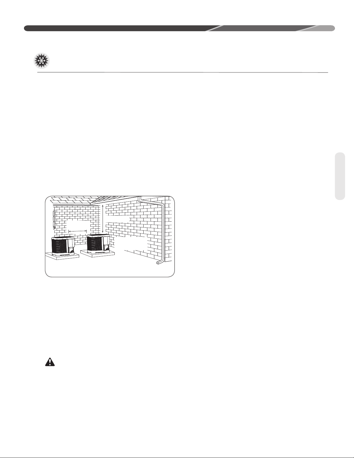
For Units With Space
Limitations
In the event that a space limitation exists, we will
permit the following clearances:
Single-Unit Applications: Side clearances below 6"
[15.2 cm] will reduce unit capacity and efficiency.
Do not reduce the 60" [152.4 cm] discharge or the
24" [61.0 cm] service clearances.
Multiple-Unit Applications: When multiple
condenser grille sides are aligned, a 6" [15.2
cm] per unit side clearance is recommended for
a total of 12" [30.5 cm] between two units. Two
combined clearances below 12" [30.5 cm] will
reduce capacity and efficiency. Do not reduce the
60" [152.4 cm] discharge or 24" [61.0 cm] service
clearances.
• If installing a unit on a flat roof, use 4" x 4"
[10.2 cm x 10.2 cm] or equivalent stringers
positioned to distribute unit weight evenly and
prevent noise and vibration.
Factory-Preferred Tie-Down
Method for High Wind or
Seismic Loads
IMPORTANT: The manufacturer-
approved/recommended method is a guide to
securing equipment for wind and seismic loads.
Other methods might provide the same result, but
the manufacturer method is the only one endorsed
by the manufacturer for securing equipment where
wind or earthquake damage can occur. Additional
information is available in the PTS (Product
Technical Support) section of the manufacturer’s
Web sites MyRheem.com or MyRuud.com and
can be found as a listing under each outdoor
model. If you do not have access to this site, your
distributor can offer assistance.
Location
Customer Satisfaction Issues
• The unit should be located away from the living,
sleeping, and recreational spaces of the owner
and those spaces on adjoining property.
• To prevent noise transmission, the mounting pad
for the outdoor unit should not be connected to
the structure and should be located a sufficient
distance above grade to prevent ground water
from entering the unit.
Unit Mounting
WARNING: Secure an elevated unit
and its elevating stand in order to prevent tipping.
Failure to do so may result in severe personal
injury or death.
9
Page 10
INSTALLATION
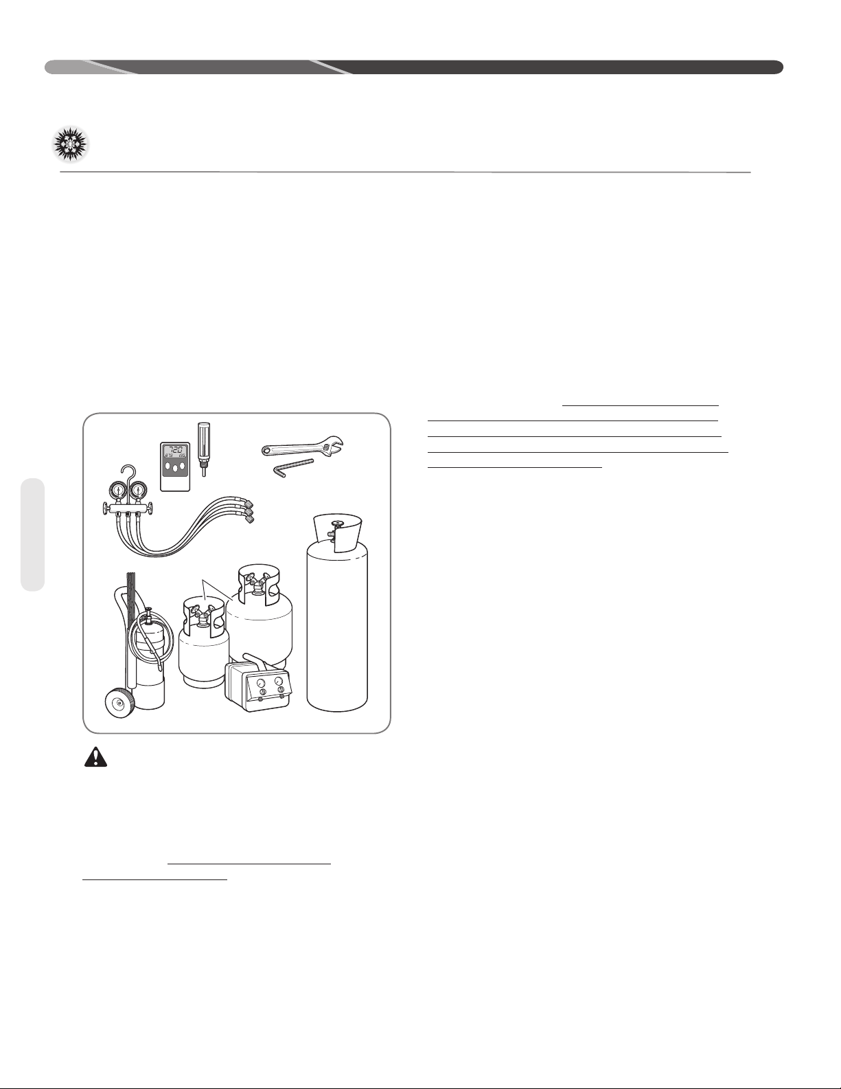
Ambient and Tube
Thermometers
Manifold
Gauge
Set
Brazing
Rods
Torch Nitrogen
Reclaimer
Recovery
Cylinders
Allen Wrench
Crescent Wrench
Tools and Refrigerant
Tools
10
Tools Required for Installing
and Servicing R-410A Models
Manifold Sets:
– Up to 800 PSIG High-Side
– Up to 250 PSIG Low-Side
– 550 PSIG Low-Side Retard
Manifold Hoses:
– Service Pressure Rating of 800 PSIG
Recovery Cylinders:
– 400 PSIG Pressure Rating
– Dept. of Transportation 4BA400 or BW400
CAUTION: R-410A systems operate
at higher pressures than R-22 systems. Do not
use R-22 service equipment or components on
R-410A equipment.
Specifications of R-410A
Application: R-410A is not a drop-in
replacement for R-22. Equipment designs must
accommodate its higher pressures. It cannot be
retrofitted into R-22 heat pumps.
Physical Properties: R-410A has an atmospheric
boiling point of -62.9°F [-52.7°C] and its saturation
pressure at 77°F [25°C] is 224.5 psig.
Composition: R-410A is a near-azeotropic
mixture of 50% by weight difluoromethane (HFC-
32) and 50% by weight pentafluoroethane (HFC-
125).
Pressure: The pressure of R-410A is
approximately 60% (1.6 times) greater than
R-22. Recovery and recycle equipment, pumps,
hoses, and the like must have design pressure
ratings appropriate for R-410A. Manifold sets
need to range up to 800 psig high-side and 250
psig low-side with a 550 psig low-side retard.
Hoses need to have a service pressure rating of
800 psig. Recovery cylinders need to have a 400
psig service pressure rating, DOT 4BA400 or DOT
BW400.
Combustibility: At pressures above 1
atmosphere, a mixture of R-410A and air can
become combustible. R-410A and air should
never be mixed in tanks or supply lines or
be allowed to accumulate in storage tanks.
Leak checking should never be done with a
mixture of R-410A and air. Leak-checking can
be performed safely with nitrogen or a mixture of
R-410A and nitrogen.
Quick-Reference Guide For
R-410A
• R-410A refrigerant operates at approximately
60% higher pressure (1.6 times) than R-22.
Ensure that servicing equipment is designed to
operate with R-410A.
• R-410A refrigerant cylinders are light rose in
color.
• R-410A, as with other HFCs, is only compatible
with POE oils.
• Vacuum pumps will not remove moisture from
POE oil used in R-410A systems.
• R-410A systems are to be charged with liquid
refrigerants. Prior to March 1999, R-410A
refrigerant cylinders had a dip tube. These
cylinders should be kept upright for equipment
charging. Post-March 1999 cylinders do not
have a dip tube and should be inverted to ensure
liquid charging of the equipment.
• Do not install a suction line filter drier in the
liquid line.
• A factory-approved biflow liquid line filter drier
is shipped with every unit and must be installed
in the liquid line at the time of installation. Only
manufacturer-approved liquid line filter driers can
be used. These are Sporlan (CW083S) and Alco
(80K083S) driers. These filter driers are rated for
minimum working pressure of 600 psig. The filter
drier will only have adequate moisture-holding
capacity if the system is properly evacuated.
• Desiccant (drying agent) must be compatible for
POE oils and R-410A refrigerant.
Page 11
Replacement Units
INSTALLATION
To prevent failure of a new unit, the existing line set
must be correctly sized and cleaned or replaced.
Care must be exercised that the expansion device
is not plugged. For new and replacement units, a
liquid line filter drier must be installed and refrigerant
tubing must be properly sized. Test the oil for acid. If
positive, a suction line filter drier is mandatory.
Indoor Coil
CAUTION: Only use evaporators
approved for use on R-410A systems that are
specifically matched with the outdoor unit per
the manufacturer’s specification sheets. Use
of existing R-22 evaporators can introduce
mineral oil to the R-410A refrigerant, forming two
different liquids and decreasing oil return to the
compressor. This can result in compressor failure.
REFER TO INDOOR COIL MANUFACTURER’S
INSTALLATION INSTRUCTIONS.
IMPORTANT: The manufacturer is not
responsible for the performance and operation of
a mismatched system or for a match listed with
another manufacturer’s coil.
IMPORTANT: When replacing an
R-22 unit with an R-410A unit, either replace
the line set or ensure that residual mineral oil is
drained from existing lines, including oil trapped in
low spots.
The thermostatic expansion valve in the
matching coil is specifically designed to operate
with R-410A. DO NOT use an R-22 TXV or
evaporator. The existing evaporator must
be replaced with the factory-specified TXV
evaporator specifically designed for R-410A.
Location
Do not install the indoor coil in the return duct
system of a gas or oil furnace. Provide a service
inlet to the coil for inspection and cleaning. Keep
the coil pitched toward the drain connection.
CAUTION: When coil is installed
over a finished ceiling and/or living area, it is
required that a secondary condensate pan be
installed under entire unit. Failure to do so can
result in property damage.
Tubing
Interconnecting Tubing
The purpose of this section is to specify the
best construction/sizing practices for installing
interconnection tubing between the indoor and
outdoor unit.
Refrigerant Level Adjustment
All units are factory-charged with R-410A
refrigerant to cover 15 feet of standard size
interconnecting liquid and vapor lines with a
required fi eld installed fi lter drier. Adjustment of
charge may be necessary even if the application
has exactly 15 feet of line set due to other
installation variables such as pressure drop,
vertical lift, and indoor coil size. For diff erent
lengths, adjust the charge as indicated below.
adjust the charge as indicated below.
• 1/4” ± .3 oz./foot [6.4 mm ± 8.5 g/.30 m]
• 5/16” ± .4 oz./foot [7.9 mm ± 11.3 g/.30 m]
• 3/8” ± .6 oz./foot [9.5 mm ± 17.0 g/.30 m]
• 1/2” ± 1.2 oz./foot [12.7 mm ± 34.0 g/.30 m]
• 6 oz. Required factory supplied fi eld installed
• fi lter dry
Charge Adjustment = (Line Set (oz. /ft.) x Total
Length) – Factory Charge for Line Set
Example: A three ton condensing unit with factory
installed 3/8” liquid service valve
requires 75 ft of line set with a liquid line diameter
of 1/2”.
Factory Charge for Line Set = 15ft x .6 oz. = 9 oz.
Charge Adjustment = (1.2 oz. x 75 ft.) – 9 oz. =
+81 oz.
11
Page 12
INSTALLATION
Interconnecting Tubing (cont.)
Tubing
Interconnecting Tubing and
Fitting Losses
Refrigerant tubing is measured in terms of actual
length and equivalent length. Actual length is used
for refrigerant charge applications. Equivalent
length takes into account pressure losses from
Equivalent Length for Fings ()
90° Short
Line Size
(in)
3/8 1.3 0.8 0.3 6 4 0.4 6
1/2 1.4 0.9 0.4 9 5 0.6 6
5/8 1.5 1 0.5 12 6 0.8 6
3/4 1.9 1.3 0.6 14 7 0.9 6
7/8 2.3 1.5 0.7 15 8 1 6
1-1/8 2.7 1.8 0.9 22 12 1.5 6
Radius
Elbow
90° Long
Radius
Elbow
45°
Elbow
Liquid Line Selection
The purpose of the liquid line is to transport warm
sub-cooled liquid refrigerant from the outdoor unit
to the indoor unit. It is important not to allow the
refrigerant to fl ash any superheated vapor prior
to the expansion device of the indoor coil. The
fl ashing of refrigerant can occur for the following
reasons:
• Low refrigerant charge
• Improperly selected liquid line size
• Absorption of heat prior to expansion device
• Excessive vertical rise between the condenser
and evaporator
Table 2 lists the equivalent length per 25’ of liquid
line at various diameters up to 300’. The total pres-
tubing length, fi ttings, vertical separation, acces-
sories, and fi lter dryers. The table below references
diff erent commonly used equivalent lengths.
Table 1
Solenoid
Valve
sure drop allowed for the liquid line is 50 PSI. The
procedure for selecting the proper liquid line is as
follows:
• Measure the total amount of vertical rise
• Measure the total amount of liquid line needed
• Add all of the equivalent lengths associated with
any fi ttings or accessories using the table above.
• Add the total length and fi tting pressure drop.
This will equal your total equivalent length.
• Round-down the total equivalent length to the
closest value in Table 2.
• Reference Table 2 to verify the round-down value of the calculated equivalent length is compatible with the required vertical rise and diameter
of liquid line.
Check
Valve
Site
Glass
Filter
Dryer
12
Note: Elevaon is defined as the
highest point of the line set to the
lowest
Page 13
Interconnecting Tubing (cont.)
RA13
OD Model
Compressor
Name Plate Oil
Charge (oz)
RA1318AJ
RA1318AJ
Alternate
RA1324AJ
RA1330AJ
RA1336AJ
RA1342AJ
RA1348AJ
RA1360AJ
RA1336AC
RA1342AC
RA1348AC
RA1360AC
RA1336AD
RA1342AD
RA1348AD
RA1360AD
RA1348AY
RA1360AY
ZP14KAE-PFV-130
ZP14K6E-PFC-130
ZP20KAE-PFV-130
ZP24K5E-PFV-130
ZP31K6E-PFV-130
ZP34K5E-PFV-130
ZP42K5E-PFV-130
ZP51K5E-PFV-130
ZP31K6E-TF5-130
ZP34K5E-TF5-130
ZP42K5E-TF5-130
ZP51K5E-TF5-130
ZP31K6E-TFD-130
ZP34K5E-TFD-130
ZP42K5E-TFD-130
ZP51K5E-TFD-130
ZP42K5E-TFE-130
ZP51K5E-TFE-130
21
21
21
25
25
42
42
42
25
42
42
42
25
42
42
42
42
42
Factory
Installed
CCH
N
N
N
N
N
N
N
N
N
N
N
N
N
N
N
N
N
N
Example: A 3-Ton condensing unit is installed 50’
below the ID unit, requires a 75’ of 1/2” diameter
liquid line, and 4 90° LR elbows.
• Fitting Equivalent Length (ft.) = 4 x .9 = 3.6’
• Total Equivalent Length (ft.) = 75’ + 3.6’ = 78.6’
• Rounded-down value (ft.) = 75’
Liquid Line
R-410A
System
Capacit y
Model
(excerpt fromTable 2, page 16)
Size
Connection
Size (Inch
I.D.) [mm]
37 3/8" [9. 53]
Liquid Line
Size (Inch
O.D.) [mm]
1/4 [6.35] 25 [7.62]
5/16 [7.94] 25 [7.62] 50 [15.24] 60 [18. 29] 45 [13.72] 35 [10.67] 20 [6.1] 5 [1.52]
3/8 [9.53] 25 [7.62] 50 [15.24] 75 [22.86] 80 [24.38] 80 [24.38] 75 [22.86] 70 [21.34] 65 [19.81] 60 [18.29] 55 [16.76] 50 [15.24] 45 [13.72]
7/16 [11.12] 25 [7.62] 50 [15.24] 75 [22.86] 95 [28.96] 90 [27.43] 90 [27.43] 85 [25.91] 85 [25.91] 85 [25.91] 80 [24.38] 80 [24.38] 80 [24.38]
1/2 [12.71] 25 [7.62] 50 [15.24] 75 [22. 86] 95 [28.96] 95 [28.96] 95 [28.96] 95 [28.96] 95 [28.96] 95 [28.96] 90 [27.43] 90 [27.43] 90 [27.43]
25 [7.62] 50 [15.24] 75 [22.86] 100 [30.48] 125 [45.72] 150 [45.72] 175 [53.34] 200 [60.96] 225 [68.58] 250 [76.20] 275 [83.82] 300 [91. 44]
N/R N/R N/R N/R N/R N/R N/R N/R N/R N/R N/R
This application is acceptable because the 50’
vertical rise is less than the maximum rise of 75’ for
this application. The application is also considered
to have a long line set. Reference the long line set
section of the I&O for detail.
Long Line Set Applications
Long line set applications are defi ned as ap-
plications that require accessories or alternate
construction methods. The following are special
considerations that need to be addressed when
installing a long line set application:
• Additional refrigerant charge
• Fitting losses and maximum equivalent length
considerations
• Refrigerant migration during the off cycle
• Oil return to the compressor
• Capacity losses
• System oil level adjustment
Liquid Line S ize
Elevation (Above or Below) Indoor Coil
Tot al
Equi val ent
Vertic al Separation - Feet [m ]
Maximum
INSTALLATION
Length - Feet [ m]
N/R N/R N/R N/R N/R
Tubing
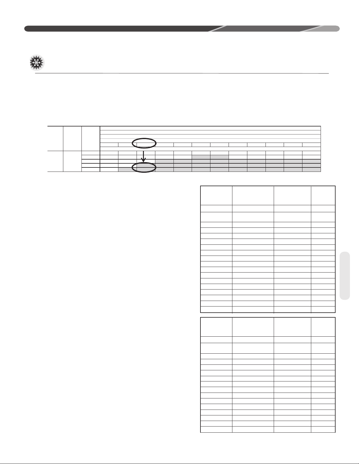
Table 2 is used to determine if the application is
considered to have a long line set. The region of
the chart that is shaded grey is considered to
be a long line set application.
Oil Level Adjustments for
Long Line Set Applications
Additional oil will need to be added for long line set
applications. (Ref. Table 2). Below is the equation
for the oil level adjustment and the compressor
name plate oil charge for the diff erent od units.
Oil to be Added = [(Charge Adjustment + OD
Unit Name Plate Charge (oz.)) x (0.022) – [(0.10)
x (Compressor Name Plate Oil Charge (oz.))]
Example: An application requires 125ft of line set
with a liquid line diameter of 3/8”, Charge Adjustment = 52.4 oz., Name Plate Charge = 107 oz.,
Name Plate Oil Charge = 25 oz., Oil to be Added =
((52.4 oz. +107 oz.) x .022) – (.10 x 25 oz.) = 1.0 oz.
RA14
OD Model
RA1418AJ
RA1418AJ
Alternate
RA1424AJ
RA1430AJ
RA1436AJ
RA1442AJ
RA1448AJ
RA1460AJ
RA1436AC
RA1442AC
RA1448AC
RA1460AC
RA1436AD
RA1442AD
RA1448AY
RA1460AY
Compressor
ZP14KAE-PFV-130
ZP14K6E-PFC-130
ZP20KAE-PFV-130
ZP24K5E-PFV-130
ZP29K5E-PFV-130
ZP34K5E-PFV-130
ZP39K5E-PFV-130
ZP49K6E-PFV-130
ZP31K6E-TF5-130
ZP34K5E-TF5-130
ZP42K5E-TF5-130
ZP51K5E-TF5-130
ZP31K6E-TFD-130
ZP34K5E-TFD-130
ZP42K5E-TFD-130
ZP51K5E-TFD-130
Name Plate Oil
Charge (oz)
21
21
21
25
25
42
42
42
25
42
42
42
25
42
42
42
Factory
Installed
CCH
N
N
N
N
N
N
N
N
N
N
N
Y
N
N
N
Y
13
Page 14
INSTALLATION
Interconnecting Tubing (cont.)
RA14XXW
OD Model
RA1418WJ
RA1424WJ
RA1430WJ
RA1436WJ
RA1442WJ
RA1436WC
RA1442WC
RA16
OD Model
RA1618AJ
RA1624AJ
RA1630AJ
RA1636AJ
RA1642AJ
RA1648AJ
RA1660AJ
RA1660BJ
RA1636AC
RA1642AC
RA1648AC
RA1660AC
Compressor
ZP14K6E-PFV-130
ZP21K6E-PFV-130
ZP24K6E-PFV-130
ZP31K6E-PFV-130
ZP34K6E-PFV-130
ZP31K6E-TF5-130
ZP34K6E-TF5-130
Compressor
ZP14K6E-PFV-130
ZP21K6E-PFV-130
ZP24K6E-PFV-130
ZP31K6E-PFV-130
ZP34K6E-PFV-130
ZP38K6E-PFV-130
ZP49K6E-PFV-130
ZP49K6E-PFV-130
ZP31K6E-TF5-130
ZP34K6E-TF5-130
ZP38K6E-TF5-130
ZP49K6E-TF5-130
Name Plate Oil
Charge (oz)
21
21
25
25
42
25
42
Name Plate Oil
Charge (oz)
21
21
25
25
42
42
42
42
42
42
42
42
Suction Line Selection
Purpose of the suction line is to return superheated
vapor to the condensing unit from the evaporator.
Proper suction line sizing is important because it
plays an important role in returning oil to the com-
Tubing
OUTDOOR UNIT LEVEL OR NEAR LEVEL TO INDOOR SECTION LINE SET
Factory
Installed
CCH
N
N
N
N
N
N
N
Factory
Installed
CCH
N
N
N
N
N
N
Y
Y
N
N
Y
Y
pressor to prevent potential damage to the bearings, valves, and scroll sets. Also, an improperly
sized suction line can dramatically reduce capacity
and performance of the system. The procedure for
selecting the proper suction line is as follows:
• The total amount of suction line needed
• Add all of the equivalent lengths associated with
any fi ttings or accessories using the table on
previous page.
• Add the total length and fi tting pressure drop.
This will equal your total equivalent length.
• Reference Table 2 to verify that the calculated
equivalent length falls within the compatibility
region of the chart.
• Verify Table 3 to verify the capacity diff erence is
compatible with the application.
Refrigerant Migration During
Off Cycle
Long line set applications can require a considerable amount of additional refrigerant. This additional refrigerant needs to be managed throughout the
entire ambient operating envelope that the system
will go through during its life cycle. Off -Cycle mi-
gration is where excess refrigerant condenses and
migrates to the lowest part of the system. Excessive build-up of refrigerant at the compressor will
result in poor reliability and noisy operation during
startup. This section demonstrates the required
accessories and unit confi guration for diff erent ap-
plications.
REFERENCE TABLE 2 FOR
MAXIMUM LENGTH LIMITATIONS
IDEALLY, LINE SET SLOPES AWAY
FROM OUTDOOR. VERIFY
SUB-COOLING PRIOR TO
THROTTLEING DEVICE, INSULATED
LIQUID LINE.
ST-A1219-01-01
14
Page 15
Interconnecting Tubing (cont.)
INSTALLATION
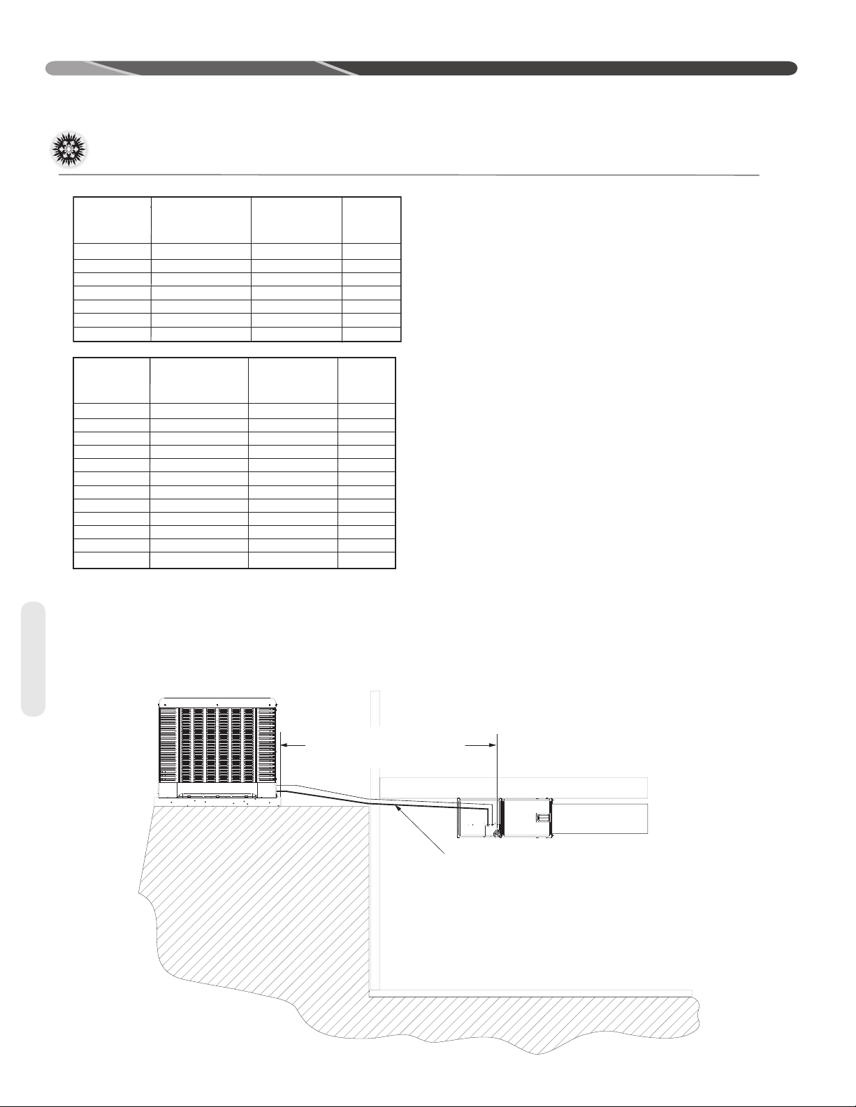
For applications that are considered to have a long
line set with the outdoor unit and indoor unit on the
same level the following is required:
• TXV or EEV on the indoor unit
• Start components may be required depending
upon quality of voltage (consistently <200vac at
outdoor unit)
• Crankcase heater (Some models have factory
installed CCH's. Refer to tables on pages 13 and
14.)
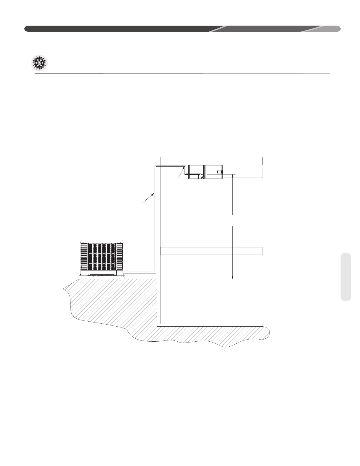
OUTDOOR UNIT BELOW INDOOR SECTION LINE SET
ROUTE
REFIGERANT LINES
EVEN WITH TOP OF
COIL OR INSTALL
INVERTED TRAP.
INSULATE
LIQUID AND
SUCTION LINE
• Insulated liquid and suction line in unconditioned
space only.
• Vapor line should slope toward the indoor unit
• Follow the proper line sizing, equivalent length,
charging requirements, and oil level adjustments
spelled out in this document and the outdoor
units I&O
• Verify at least 5°F sub-cooling at the ID unit prior
to throttling device
REFERENCE TABLE 2 FOR
MAXIMUM LENGTH
LIMITATIONS
For applications that are considered to have a long
line set with the outdoor unit below the indoor unit
the following is required:
• TXV or EEV at the IDunit
•
Crankcase heater (Some moels come with factory
installed CCH's. Refer to tables on page 13 & 14.)
• Start components may be required depending
upon quality of voltage (consistently <200vac at
outdoor unit)
• Refrigerant lines should be routed even with the
top of the ID coil or an inverted trap is to be applied. (Reference fi gure 4).
ST-A1219-02-02
Figure 4
• Insulated liquid and suction line in unconditioned space only.
• Follow the proper line sizing, equivalent length,
charging requirements, and oil level adjustments
spelled out in this document and the outdoor
units I&O
• Measure pressure at the liquid line service valve
and prior to expansion device. Verify that it is
not greater than 50 PSI
• For elevations greater that 25’ can expect a
lower sub-cooling
Tubing
15
Page 16

INSTALLATION
Interconnecting Tubing (cont.)
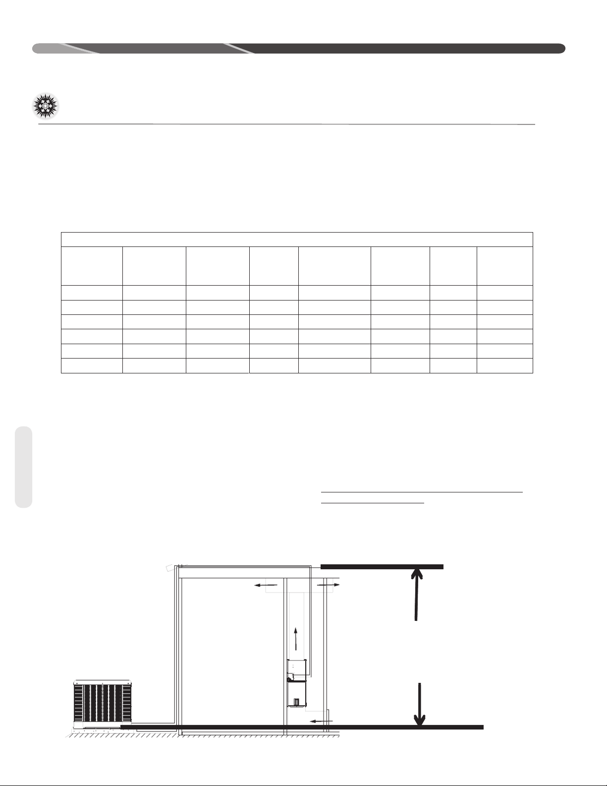
OUTDOOR UNIT ABOVE INDOOR SECTION LINE SET
INSULATE LIQUID AND
SUCTION LINE
REFERENCE TABLE 2
FOR ELEVATION
LIMITATIONS
Tubing
VERIFY
SUB-COOLING
PRIOR TO
THROTTLING
DEVICE
For applications that are considered to have a long
line set with the outdoor unit above the indoor unit
the following is required:
• TXV at the indoor unit
• Crankcase heater (some models have factory
installed CCH's. Refer to tables on pages 13 &
14).
• Start components maybe required depending
upon quality of voltage (consistently <200vac at
outdoor unit)
TXV OR EEV AT INDOOR
EVAPORATOR
• Insulated liquid and suction line in unconditioned
space only.
• Follow the proper line sizing, equivalent length,
charging requirements, and oil level adjustments
spelled out in this document and the outdoor
units I&O
• Verify at least 5°F sub-cooling at the ID unit prior
to throttling device
16
Page 17

NOTES:
N/R = Application not recommended.
60 3/8" [9.53]
48 3/8" [9.53]
42 3/8" [9.53]
Table 2
36
3/8" [9.53]
30
3/8" [9.53]
24 3/8" [9.53]
R-410A System
Capacity Model
Size (Inch I.D.)
3/8" [9.53]18
[mm]
Connection
Interconnecting Tubing
Liquid Line Size
INSTALLATION
7/16 [11.12] 25 [7.62] 45 [13.72] 40 [12.19] 35 [10.67] 30 [9.14] 25 [7.62] 20 [6.1] 15 [4.57] 10 [3.05] N/R N/R N/R
1/2 [12.71] 25 [7.62] 50 [15.24] 45 [13.72] 45 [13.72] 40 [12.19] 40 [12.19] 35 [10.67] 35 [10.67] 30 [9.14] 30 [9.14] 25 [7.62] 25 [7.62]
3/8 [9.53] 25 [7.62] 30 [9.14] 20 [6.1] 5 [1.52] N/R N/R N/R N/R N/R N/R N/R N/R
5/16 [7.94] 20 [6.1] N/R N/R N/R N/R N/R N/R N/R N/R N/R N/R N/R
5/16 [7.94] 25 [7.62] 50 [15.24] 50 [15.24] 30 [9.14] 15 [4.57] N/R N/R N/R N/R N/R N/R N/R
1/4 [6.35] 25 [7.62] N/R N/R N/R N/R N/R N/R N/R N/R N/R N/R N/R
1/2 [12.71] 25 [7.62] 50 [15.24] 75 [22.86] 100 [30.48] 100 [30.48] 95 [28.96] 95 [28.96] 95 [28.96] 95 [28.96] 95 [28.96] 90 [27.43] 90 [27.43]
7/16 [11.12] 25 [7.62] 50 [15.24] 75 [22.86] 95 [28.96] 95 [28.96] 90 [27.43] 90 [27.43] 85 [25.91] 85 [25.91] 85 [25.91] 80 [24.38] 80 [24.38]
3/8 [9.53] 25 [7.62] 50 [15.24] 75 [22.86] 85 [25.91] 80 [24.38] 75 [22.86] 70 [21.34] 65 [19.81] 60 [18.29] 60 [18.29] 55 [16.76] 50 [15.24]
7/16 [11.12] 25 [7.62] 50 [15.24] 75 [22.86] 85 [25.91] 80 [24.38] 80 [24.38] 75 [22.86] 70 [21.34] 70 [21.34] 65 [19.81] 60 [18.29] 60 [18.29]
1/2 [12.71] 25 [7.62] 50 [15.24] 75 [22.86] 90 [27.43] 90 [27.43] 90 [27.43] 85 [25.91] 85 [25.91] 85 [25.91] 80 [24.38] 80 [24.38] 80 [24.38]
3/8 [9.53] 25 [7.62] 50 [15.24] 75 [22.86] 65 [19.81] 60 [18.29] 50 [15.24] 45 [13.72] 35 [10.67] 25 [7.62] 20 [6.1] 10 [3.05] N/R
1/4 [6.35] N/R N/R N/R N/R N/R N/R N/R N/R N/R N/R N/R N/R
7/16 [11.12] 25 [7.62] 50 [15.24] 75 [22.86] 95 [28.96] 90 [27.43] 90 [27.43] 85 [25.91] 80 [24.38] 80 [24.38] 75 [22.86] 75 [22.86] 70 [21.34]
1/2 [12.71] 25 [7.62] 50 [15.24] 75 [22.86] 100 [30.48] 95 [28.96] 95 [28.96] 95 [28.96] 95 [28.96] 90 [27.43] 90 [27.43] 90 [27.43] 90 [27.43]
5/16 [7.94] 25 [7.62] 50 [15.24] 30 [9.14] 5 [1.52] N/R N/R N/R N/R N/R N/R N/R N/R
1/4 [6.35] 5 [1.52] N/R N/R N/R N/R N/R N/R N/R N/R N/R N/R N/R
3/8 [9.53] 25 [7.62] 50 [15.24] 75 [22.86] 80 [24.38] 70 [21.34] 65 [19.81] 60 [18.29] 55 [16.76] 50 [15.24] 40 [12.19] 35 [10.67] 30 [9.14]
5/16 [7.94] 25 [7.62] 50 [15.24] 65 [19.81] 50 [15.24] 35 [10.67] 25 [7.62] 10 [3.05] N/R N/R N/R N/R N/R
1/2 [12.71] 25 [7.62] 50 [15.24] 75 [22.86] 100 [30.48] 100 [30.48] 100 [30.48] 100 [30.48] 100 [30.48] 100 [30.48] 100 [30.48] 95 [28.96] 95 [28.96]
1/4 [6.35] 25 [7.62] N/R N/R N/R N/R N/R N/R N/R N/R N/R N/R N/R
7/16 [11.12] 25 [7.62] 50 [15.24] 75 [22.86] 100 [30.48] 95 [28.96] 95 [28.96] 95 [28.96] 95 [28.96] 90 [27.43] 90 [27.43] 90 [27.43] 85 [25.91]
7/16 [11.12] 25 [7.62] 50 [15.24] 75 [22.86] 100 [30.48] 105 [32] 105 [32] 100 [30.48] 100 [30.48] 100 [30.48] 100 [30.48] 100 [30.48] 95 [28.96]
1/2 [12.71] 25 [7.62] 50 [15.24] 75 [22.86] 100 [30.48] 105 [32] 105 [32] 105 [32] 105 [32] 105 [32] 105 [32] 105 [32] 105 [32]
5/16 [7.94] 25 [7.62] 50 [15.24] 75 [22.86] 65 [19.81] 55 [16.76] 45 [13.72] 35 [10.67] 25 [7.62] 15 [4.57] 5 [1.52] N/R N/R
1/4 [6.35] 25 [7.62] 25 [7.62] N/R N/R N/R N/R N/R N/R N/R N/R N/R N/R
3/8 [9.53] 25 [7.62] 50 [15.24] 75 [22.86] 90 [27.43] 90 [27.43] 85 [25.91] 80 [24.38] 80 [24.38] 75 [22.86] 70 [21.34] 65 [19.81] 65 [19.81]
3/8 [9.53] 25 [7.62] 50 [15.24] 75 [22.86] 100 [30.48] 100 [30.48] 95 [28.96] 95 [28.96] 90 [27.43] 90 [27.43] 85 [25.91] 85 [25.91] 80 [24.38]
7/16 [11.12] 25 [7.62] 50 [15.24] 75 [22.86] 100 [30.48] 105 [32] 105 [32] 105 [32] 105 [32] 105 [32] 105 [32] 105 [32] 105 [32]
5/16 [7.94] 25 [7.62] 50 [15.24] 75 [22.86] 85 [25.91] 75 [22.86] 70 [21.34] 65 [19.81] 55 [16.76] 50 [15.24] 45 [13.72] 40 [12.19] 30 [9.14]
1/4 [6.35] 25 [7.62] 50 [15.24] 35 [10.67] 10 [3.05] N/R N/R N/R N/R N/R N/R N/R N/R
1/2 [12.71] 25 [7.62] 50 [15.24] 75 [22.86] 100 [30.48] 110 [33.53] 110 [33.53] 110 [33.53] 110 [33.53] 105 [32] 105 [32] 105 [32] 105 [32]
3/8 [9.53] 25 [7.62] 50 [15.24] 75 [22.86] 100 [30.48] 105 [32] 100 [30.48] 100 [30.48] 100 [30.48] 100 [30.48] 95 [28.96] 95 [28.96] 95 [28.96]
5/16 [7.94] 25 [7.62] 50 [15.24] 75 [22.86] 95 [28.96] 90 [27.43] 90 [27.43] 85 [25.91] 80 [24.38] 75 [22.86] 75 [22.86] 70 [21.34] 65 [19.81]
1/4 [6.35] 25 [7.62] 50 [15.24] 65 [19.81] 50 [15.24] 40 [12.19] 25 [7.62] 10 [3.05] N/R N/R N/R N/R N/R
Liquid Line Size
(Inch O.D.)
[mm]
25 [7.62] 50 [15.24] 75 [22.86] 100 [30.48] 125 [45.72] 150 [45.72] 175 [53.34] 200 [60.96] 225 [68.58] 250 [76.20] 275 [83.82] 300 [91.44]
Maximum Vertical Separation - Feet [m]
Elevation Above or Below Indoor Coil
Total Equivalent Length - Feet [m]
Liquid Line Size
Tubing
17
Page 18
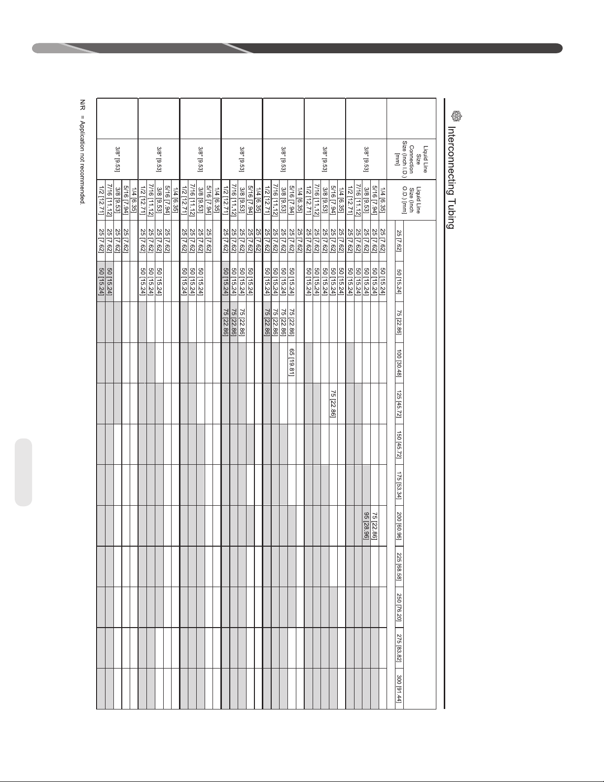
Table 2 cont.
Grey = Considered a Long Line Set Applicaon.
NOTES:
60
48
42
36
30
24
18
Capacity Model
R-410A
System
RA14
INSTALLATION
Tubing
N/R N/R N/R N/R
45 [13.72]
5 [1.52]
35 [10.67]
55 [16.76]
60 [18.29]
50 [15.24]
60 [18.29]
45 [13.72]
55 [16.76]
40 [12.19]
55 [16.76]
35 [10.67]
55 [16.76]
50 [15.24]
30 [9.14]
75 [22.86]
N/R N/R N/R N/R
80 [24.38]
25 [7.62]
80 [24.38]
15 [4.57]
N/R
75 [22.86]
N/R N/R
N/R
75 [22.86]
N/R N/R
N/R
75 [22.86]
N/R N/R
N/R N/R N/R
N/R N/R N/R N/R
40 [12.19]
75 [22.86]
65 [19.81]
55 [16.76]
75 [22.86]
50 [15.24]
70 [21.34]
40 [12.19]
65 [19.81]
35 [10.67]
65 [19.81]
60 [18.29]
25 [7.62]
75 [22.86]
75 [22.86]
20 [6.1]
80 [24.38]
85 [25.91]
N/R
75 [22.86]
80 [24.38]
N/R
N/R
75 [22.86]
80 [24.38]
N/R N/R N/R N/R
N/R
70 [21.34]
80 [24.38]
N/R
70 [21.34]
80 [24.38]
N/R
5 [1.52]
50 [15.24]
N/R N/R
70 [21.34]
35 [10.67]
100 [30.48]
65 [19.81]
15 [4.57]
N/R N/R N/R
100 [30.48]
60 [18.29]
N/R N/R
95 [28.96]
50 [15.24]
95 [28.96]
45 [13.72]
N/R
N/R
40 [12.19]
95 [28.96]
N/R
N/R N/R
10 [3.05]
65 [19.81]
N/R N/R
100 [30.48]
100 [30.48]
55 [16.76]
85 [25.91]
95 [28.96]
100 [30.48]
100 [30.48]
45 [13.72]
80 [24.38]
95 [28.96]
N/R
100 [30.48]
80 [24.38]
90 [27.43]
75 [22.86]
90 [27.43]
70 [21.34]
90 [27.43]
30 [9.14]
N/R
100 [30.48]
20 [6.1]
N/R
100 [30.48]
10 [3.05]
N/R
95 [28.96]
95 [28.96]
95 [28.96]
90 [27.43]
55 [16.76]
90 [27.43]
45 [13.72]
85 [25.91]
35 [10.67]
80 [24.38]
80 [24.38]
25 [7.62]
25 [7.62]
75 [22.86]
75 [22.86]
N/R
100 [30.48]
100 [30.48]
N/R
100 [30.48]
105 [32]
N/R
100 [30.48]
105 [32]
N/R
100 [30.48]
105 [32]
N/R
100 [30.48]
105 [32]
N/R
75 [22.86]
75 [22.86]
30 [9.14]
80 [24.38]
95 [28.96]
N/R
95 [28.96]
N/R
70 [21.34]
95 [28.96]
N/R
60 [18.29]
90 [27.43]
N/R N/R
55 [16.76]
90 [27.43]
75 [22.86]
75 [22.86]
75 [22.86]
100 [30.48]
100 [30.48]
100 [30.48]
100 [30.48]
105 [32]
105 [32]
100 [30.48]
105 [32]
105 [32]
100 [30.48]
80 [24.38]
105 [32]
105 [32]
105 [32]
105 [32]
75 [22.86]
90 [27.43]
90 [27.43]
85 [25.91]
20 [6.1]
65 [19.81]
50 [15.24]
35 [10.67]
Maximum Vertical Separation - Feet [m]
N/R
N/R
Elevation Above or Below Indoor Coil
Total Equivalent Length - Feet [m]
Liquid Line Size
18
50 [15.24]
30 [9.14]
45 [13.72]
25 [7.62]
45 [13.72]
20 [6.1]
40 [12.19]
15 [4.57]
70 [21.34]
N/R N/R
70 [21.34]
N/R
70 [21.34]
N/R N/R
N/R
N/R
65 [19.81]
N/R
N/R
65 [19.81]
55 [16.76]
55 [16.76]
50 [15.24]
50 [15.24]
75 [22.86]
20 [6.1]
N/R
65 [19.81]
75 [22.86]
10 [3.05]
N/R
N/R
60 [18.29]
75 [22.86]
N/R N/R
N/R
N/R
55 [16.76]
75 [22.86]
N/R
N/R
35 [10.67]
25 [7.62]
N/R
20 [6.1]
N/R N/R
15 [4.57]
95 [28.96]
N/R
95 [28.96]
N/R
95 [28.96]
N/R
90 [27.43]
N/R
65 [19.81]
85 [25.91]
N/R N/R
N/R
60 [18.29]
85 [25.91]
N/R N/R
55 [16.76]
85 [25.91]
N/R N/R
55 [16.76]
80 [24.38]
N/R
100 [30.48]
75 [22.86]
90 [27.43]
100 [30.48]
70 [21.34]
90 [27.43]
65 [19.81]
90 [27.43]
95 [28.96]
65 [19.81]
90 [27.43]
95 [28.96]
100 [30.48]
15 [4.57]
N/R
100 [30.48]
5 [1.52]
N/R
100 [30.48]
N/R
N/R
100 [30.48]
N/R
N/R
100 [30.48]
50 [15.24]
85 [25.91]
85 [25.91]
95 [28.96]
80 [24.38]
95 [28.96]
80 [24.38]
95 [28.96]
105 [32]
105 [32]
N/R
100 [30.48]
40 [12.19]
105 [32]
N/R N/R
100 [30.48]
35 [10.67]
30 [9.14]
N/R
105 [32]
105 [32]
95 [28.96]
100 [30.48]
90 [27.43]
75 [22.86]
95 [28.96]
N/R N/R
70 [21.34]
95 [28.96]
65 [19.81]
N/R
60 [18.29]
N/R
Page 19

NOTES:
Table 2 cont.
R-410A System
Capacity Model
60
48
42
36
30
24
18
RA16
INSTALLATION
25 [7.62]
N/R
50 [15.24]
50 [15.24]
30 [9.14]
N/R N/R N/R
75 [22.86]
60 [18.29]
75 [22.86]
75 [22.86]
N/R N/R N/R N/R N/R N/R
50 [15.24]
70 [21.34]
80 [24.38]
70 [21.34]
80 [24.38]
65 [19.81]
75 [22.86]
60 [18.29]
75 [22.86]
55 [16.76]
75 [22.86]
90 [27.43]
90 [27.43]
40 [12.19]
N/R
85 [25.91]
30 [9.14]
N/R N/R
85 [25.91]
20 [6.1]
85 [25.91]
5 [1.52]
N/R N/R
15 [4.57] N/R N/R N/R
50 [15.24]
75 [22.86]
35 [10.67]
70 [21.34]
75 [22.86]
90 [27.43]
65 [19.81]
85 [25.91]
15 [4.57]
85 [25.91]
60 [18.29]
80 [24.38]
N/R
N/R
85 [25.91]
55 [16.76]
80 [24.38]
N/R N/R N/R N/R
N/R
45 [13.72]
75 [22.86]
70 [21.34]
N/R
40 [12.19]
N/R
85 [25.91]
85 [25.91]
25 [7.62]
50 [15.24]
N/R N/R
75 [22.86]
40 [12.19]
75 [22.86]
75 [22.86]
95 [28.96]
70 [21.34]
85 [25.91]
20 [6.1]
N/R N/R N/R
95 [28.96]
60 [18.29]
80 [24.38]
N/R
95 [28.96]
55 [16.76]
80 [24.38]
N/R
90 [27.43]
50 [15.24]
75 [22.86]
N/R
N/R
90 [27.43]
45 [13.72]
70 [21.34]
N/R
N/R N/R
N/R
75 [22.86]
60 [18.29]
75 [22.86]
75 [22.86]
N/R N/R
45 [13.72]
80 [24.38]
90 [27.43]
90 [27.43]
85 [25.91]
85 [25.91]
85 [25.91]
35 [10.67]
75 [22.86]
N/R
70 [21.34]
20 [6.1]
N/R
65 [19.81]
5 [1.52]
N/R
60 [18.29]
N/R
N/R
95 [28.96]
95 [28.96]
95 [28.96]
95 [28.96]
95 [28.96]
70 [21.34]
75 [22.86]
75 [22.86]
65 [19.81]
85 [25.91]
95 [28.96]
55 [16.76]
85 [25.91]
95 [28.96]
45 [13.72]
80 [24.38]
90 [27.43]
35 [10.67]
80 [24.38]
90 [27.43]
75 [22.86]
90 [27.43]
25 [7.62]
30 [9.14]
N/R
100 [30.48]
100 [30.48]
N/R
100 [30.48]
105 [32]
N/R
100 [30.48]
100 [30.48]
N/R
100 [30.48]
100 [30.48]
N/R
100 [30.48]
100 [30.48]
N/R
35 [10.67]
100 [30.48]
100 [30.48]
80 [24.38]
95 [28.96]
10 [3.05]
75 [22.86]
95 [28.96]
N/R
70 [21.34]
90 [27.43]
N/R
60 [18.29]
90 [27.43]
N/R N/R
55 [16.76]
90 [27.43]
85 [25.91]
95 [28.96]
100 [30.48]
100 [30.48]
85 [25.91]
95 [28.96]
100 [30.48]
100 [30.48]
80 [24.38]
95 [28.96]
100 [30.48]
100 [30.48]
75 [22.86]
90 [27.43]
100 [30.48]
70 [21.34]
90 [27.43]
95 [28.96]
60 [18.29]
45 [13.72]
30 [9.14]
Maximum Vertical Separation - Feet [m]
15 [4.57]
N/R
N/R
Elevation Above or Below Indoor Coil
Total Equivalent Length - Feet [m]
Liquid Line Size
Tubing
50 [15.24]
70 [21.34]
45 [13.72]
70 [21.34]
40 [12.19]
65 [19.81]
40 [12.19]
65 [19.81]
85 [25.91]
N/R N/R
N/R N/R
80 [24.38]
N/R
80 [24.38]
N/R N/R
N/R
N/R
80 [24.38]
N/R
N/R
70 [21.34]
70 [21.34]
65 [19.81]
65 [19.81]
60 [18.29]
80 [24.38]
30 [9.14]
N/R
65 [19.81]
80 [24.38]
25 [7.62]
N/R
N/R
65 [19.81]
80 [24.38]
20 [6.1]
N/R N/R
N/R
60 [18.29]
80 [24.38]
10 [3.05]
N/R
40 [12.19]
30 [9.14]
N/R
25 [7.62]
N/R N/R
20 [6.1]
90 [27.43]
N/R
90 [27.43]
N/R
90 [27.43]
N/R
85 [25.91]
N/R
60 [18.29]
80 [24.38]
N/R N/R
N/R
55 [16.76]
80 [24.38]
N/R N/R
50 [12.24]
75 [22.86]
N/R N/R
45 [13.72]
75 [22.86]
N/R
70 [21.34]
90 [27.43]
95 [28.96]
70 [21.34]
85 [25.91]
95 [28.96]
65 [19.81]
85 [25.91]
95 [28.96]
60 [18.29]
85 [25.91]
90 [27.43]
100 [30.48]
20 [6.1]
N/R
100 [30.48]
10 [3.05]
N/R
100 [30.48]
N/R
N/R
100 [30.48]
N/R
N/R
100 [30.48]
95 [28.96]
50 [15.24]
85 [25.91]
95 [28.96]
N/R
100 [30.48]
45 [13.72]
85 [25.91]
95 [28.96]
80 [24.38]
95 [28.96]
80 [24.38]
95 [28.96]
95 [28.96]
N/R N/R
100 [30.48]
40 [12.19]
95 [28.96]
100 [30.48]
95 [28.96]
30 [9.14]
N/R
70 [21.34]
90 [27.43]
N/R N/R
65 [19.81]
90 [27.43]
60 [18.29]
85 [25.91]
N/R
50 [15.24]
85 [25.91]
N/R
19
Page 20

NOTES:
N/R = Application not recommended.
All calculations assume a 3/8” liquid line
60 3/4" [19.06]
48
Table 3
R-410A System
Capacity Model
42
36
30 3/4" [19.06]
24 3/4" [19.06]
18 3/4" [19.06]
RA13
3/4" [19.06]
1-1/8 [28.58] N/R N/R
1 [25.4] N/R
1.00
1.00
1.00
1.00
1.00
1.00
1.00
1.00
N/R
N/R
N/R
N/R
5/8 [15.88] 1.00
3/4 [19.05] N/R N/R N/R N/R N/R
7/8 [22.23]
1.00
1.00
0.99
1.00
1.00
0.99
1.00
1.00
0.98
1.00
1.00
N/R
N/R
N/R
N/R
N/R
N/R
1-1/8 [28.58]
3/4 [19.05]
7/8 [22.23]
1 [25.4]
1.00
1.00
1.00
N/R
1.00
1.00
1.00
N/R
1.00
1.00
1.00
N/R
1.00
1.00
1.00
N/R
1.00
1.00
1.00
N/R
0.99
1.00
1.00
N/R
1-1/8 [28.58]
5/8 [15.88] 1.00
1 [25.4]
1.00
1.00
0.99
1.00
1.00
0.99
1.00
1.00
0.98
1.00
1.00
0.98
1.00
1.00
0.98
1.00
N/R
3/4" [19.06]
5/8 [15.88] 1.00
3/4 [19.05]
7/8 [22.23]
1.00
1.00
0.99
1.00
1.00
0.99
1.00
1.00
0.98
1.00
1.00
0.98
1.00
1.00
0.98
0.99
1.00
3/4" [19.06]
1-1/8 [28.58]
3/4 [19.05]
7/8 [22.23]
1 [25.4]
1.00
1.00
1.00
1.00
1.00
1.00
1.00
1.00
1.00
1.00
1.00
1.00
1.00
1.00
1.00
1.00
1.00
1.00
1.00
1.00
0.99
1.00
1.00
1.00
1-1/8 [28.58] N/R N/R N/R N/R N/R
5/8 [15.88] 1.00
1 [25.4]
1.00
1.00
0.99
1.00
0.99
1.00
0.98
1.00
0.98
1.00
N/R
0.98
5/8 [15.88] 1.00
3/4 [19.05]
7/8 [22.23]
1.00
1.00
0.99
1.00
1.00
0.99
1.00
1.00
0.98
1.00
1.00
0.98
1.00
1.00
0.98
0.99
1.00
1-1/8 [28.58]
1 [25.4] N/R N/R N/R
N/R N/R N/R
N/R
N/R N/R
N/R
N/R
N/R
1-1/8 [28.58]
5/8 [15.88] 1.00
3/4 [19.05]
7/8 [22.23]
1.00
1.00
1.00
1.00
1.00
1.00
1.00
1.00
1.00
1.00
1.00
1.00
7/8 [22.23] N/R N/R N/R
1 [25.4]
N/R N/R N/R
N/R N/R N/R N/R
0.99
0.99
0.98
N/R
N/R
0.98
N/R
N/R N/R
N/R N/R
0.98
N/R
5/8 [15.88] 1.00
3/4 [19.05]
1.00
0.99
1.00
0.99
1.00
0.98
1.00
0.98
1.00
0.98
0.99
25 [7.62] 50 [15.24] 75 [22.86] 100 [30.48] 125 [45.72]
150 [45.72]
Total Equivalent Length - Feet [m]
Vapor Line Selection Chart
Capacity Multiplier Table
Tubing
20
N/R N/R N/R
1.00
1.00
N/R
N/R N/R N/R
N/R N/R N/R
N/R
N/R
N/R
1.00
1.00
N/R
1.00
1.01
N/R
N/R
N/R N/R
N/R
1.00
1.01
N/R
N/R
N/R
N/R
N/R
N/R
N/R
0.99
0.99
0.99
0.99
N/R
0.97
0.96
0.96
0.96
N/R
1.01
1.01
1.01
1.01
1.01
1.01
1.00
1.00
1.00
1.01
1.06
1.01
0.97
0.99
1.00
1.00
N/R
N/R N/R N/R
1.00
1.00
1.00
1.00
1.00
1.00
0.99
0.99
0.99
0.99
0.99
0.99
0.97
0.97
0.96
0.96
0.96
0.95
1.01
1.01
1.01
1.01
1.01
1.01
1.00
1.00
1.00
1.01
1.01
1.01
1.00
1.00
1.00
1.00
1.00
1.00
0.99
0.99
0.99
0.99
0.99
0.99
0.97
0.97
0.96
0.96
0.96
0.95
N/R
N/R
N/R
N/R
N/R
N/R
1.00
1.00
1.00
1.01
1.01
1.01
1.00
1.00
1.00
1.00
1.00
1.00
0.99
0.99
0.99
0.99
0.99
0.99
0.97
0.97
0.96
0.96
0.96
0.95
N/R
N/R
N/R
N/R
N/R
N/R
N/R
N/R
N/R
N/R
N/R
N/R
0.97
0.99
1.00
1.00
1.00
1.00
1.00
1.00
0.99
0.99
0.99
0.99
0.99
N/R
N/R
N/R
0.97
N/R
N/R
N/R
0.96
N/R
N/R
N/R
0.96
N/R N/R
N/R N/R
N/R N/R
0.96
0.95
N/R
N/R
N/R
0.99
0.99
0.99
0.99
0.99
0.99
0.97
0.97
0.96
0.96
0.96
0.95
175 [53.34]
200 [60.96]
225 [68.58] 250 [76.20] 275 [83.82]
300 [91.44
]
Page 21

NOTES:
N/R = Application not recommended.
60 3/8" [9.53]
48
Table 3 cont.
R-410A System
Capacity Model
42
36
30 3/8" [9.53]
24 3/8" [9.53]
18 3/8" [9.53]
RA14
3/8" [9.53]
1-1/8 [28.58] N/R N/R
1 [25.4] N/R
1.00
N/R
1.00
N/R
1.00
N/R
1.00
N/R
0.99
N/R
N/R
N/R
5/8 [15.88] 0.97
3/4 [19.05] N/R N/R N/R N/R N/R
7/8 [22.23]
0.99
1.00
0.94
0.98
0.99
0.91
0.96
0.99
0.98
0.95
0.98
0.87
0.94
0.98
N/R
N/R
N/R
1-1/8 [28.58]
3/4 [19.05]
7/8 [22.23]
1 [25.4]
0.99
1.00
1.00
N/R
0.98
1.00
1.00
N/R
0.97
0.98
0.99
N/R
0.96
0.98
0.99
N/R
0.96
0.97
0.99
N/R
0.95
0.97
0.98
N/R
1-1/8 [28.58]
5/8 [15.88] 0.98
1 [25.4]
N/R
N/R
0.95
N/R
N/R
0.93
N/R
N/R
0.92
N/R
N/R
0.9
N/R
N/R
0.88
N/R
N/R
3/8" [9.53]
5/8 [15.88] 1.00
3/4 [19.05]
7/8 [22.23]
1.00
1.00
0.97
1.00
1.00
0.95
0.99
1.01
0.93
0.99
1.00
0.92
0.97
1.00
0.91
0.97
0.99
3/8" [9.53]
1-1/8 [28.58]
3/4 [19.05]
7/8 [22.23]
1 [25.4]
1.00
1.01
N/R
N/R
1.00
1.01
N/R
N/R
0.99
1.00
N/R
N/R
0.99
1.00
N/R
N/R
0.98
1.00
N/R
N/R
0.99
0.99
N/R
N/R
1-1/8 [28.58] N/R N/R N/R N/R N/R
5/8 [15.88] 0.99
1 [25.4]
N/R
N/R
0.98
N/R
0.97
N/R
0.96
N/R
0.95
N/R
N/R
0.93
5/8 [15.88] 1.00
3/4 [19.05]
7/8 [22.23]
1.00
N/R
0.98
1.00
N/R
0.97
0.99
N/R
0.97
0.99
N/R
0.95
0.99
N/R
0.95
0.95
N/R
1-1/8 [28.58]
1 [25.4] N/R N/R N/R
N/R N/R N/R
N/R
N/R N/R
N/R
N/R
N/R
1-1/8 [28.58]
5/8 [15.88] 0.99
3/4 [19.05]
7/8 [22.23]
N/R
N/R
N/R
N/R
N/R
N/R
N/R
N/R
N/R
N/R
N/R
N/R
7/8 [22.23] N/R N/R N/R
1 [25.4]
N/R N/R N/R
N/R N/R N/R N/R
1.00
0.99
0.98
N/R
N/R
0.97
N/R
N/R N/R
N/R N/R
0.97
N/R
5/8 [15.88] 1.00
3/4 [19.05]
1.00
0.99
1.00
0.99
1.00
0.98
1.00
0.98
1.00
0.98
0.99
25 [7.62] 50 [15.24] 75 [22.86] 100 [30.48] 125 [45.72]
150 [45.72]
Outdoor unit Above or Below Indoor Coil
Total Equivalent Length - Feet [m]
Suction Line Size
Tubing
N/R N/R N/R
0.97
0.98
N/R
N/R N/R N/R
N/R N/R N/R
N/R
N/R
N/R
0.96
0.98
N/R
0.96
0.98
N/R
N/R
N/R N/R
N/R
N/R
N/R
N/R
N/R
N/R
N/R
N/R
N/R
N/R
0.93
0.92
0.92
N/R
N/R
0.85
0.84
0.82
N/R
N/R
N/R
N/R
N/R
N/R
N/R
N/R
N/R
N/R
N/R
N/R
N/R
N/R
0.86
0.94
0.97
0.98
N/R
N/R N/R N/R
0.99
0.99
0.99
0.98
0.98
0.98
0.97
0.95
0.95
0.95
0.94
0.93
0.9
0.89
0.87
0.85
0.85
0.84
N/R
N/R
N/R
N/R
N/R
N/R
N/R
N/R
N/R
N/R
N/R
N/R
0.99
0.99
0.99
0.99
0.99
0.98
0.99
0.97
0.98
0.97
0.96
0.96
0.93
0.91
0.9
0.9
0.89
0.88
N/R
N/R
N/R
N/R
N/R
N/R
N/R
N/R
N/R
N/R
N/R
N/R
N/R
N/R
N/R
N/R
N/R
N/R
0.98
0.98
0.97
0.97
0.97
0.96
0.94
0.93
0.93
0.92
0.92
0.91
N/R
N/R
N/R
N/R
N/R
N/R
N/R
N/R
N/R
N/R
N/R
N/R
0.96
N/R
N/R
N/R
N/R
N/R
N/R
N/R
N/R
N/R
N/R
N/R
N/R
N/R
N/R
N/R
0.95
N/R
N/R
N/R
0.94
N/R
N/R
N/R
0.94
N/R N/R
N/R N/R
N/R N/R
0.93
0.94
N/R
N/R
N/R
0.99
0.99
0.99
0.99
0.99
0.99
0.97
0.97
0.96
0.96
0.96
0.95
175 [53.34]
200 [60.96]
225 [68.58] 250 [76.20] 275 [83.82]
300 [91.44
]
21
Page 22

Table 3 cont.
Grey = This applicaon is acceptable, but the long line guidelines must be followed. Reference Long Line Set secon in the I&O.
NOTES:
42
15 [4.57]
36
30
24
18
Capacity Model
RA14XXW
R-410A
System
INSTALLATION
50 [15.24]
N/R N/R
70 [21.34]
75 [22.86]
75 [22.86]
35 [10.67]
95 [28.96]
65 [19.81]
80 [24.38]
85 [25.91]
15 [4.57]
N/R N/R N/R
60 [18.29]
75 [22.86]
85 [25.91]
75 [22.86]
80 [24.38]
70 [21.34]
80 [24.38]
70 [21.34]
80 [24.38]
65 [19.81]
80 [24.38]
95 [28.96]
N/R N/R
95 [28.96]
50 [15.24]
95 [28.96]
45 [13.72]
N/R
N/R
40 [12.19]
90 [27.43]
N/R
N/R N/R
35 [10.67]
90 [27.43]
N/R
N/R
55 [16.76]
N/R N/R
100 [30.48]
100 [30.48]
45 [13.72]
80 [24.38]
90 [27.43]
100 [30.48]
100 [30.48]
75 [22.86]
90 [27.43]
30 [9.14]
N/R
100 [30.48]
70 [21.34]
90 [27.43]
65 [19.81]
85 [25.91]
60 [18.29]
85 [25.91]
55 [16.76]
80 [24.38]
95 [28.96]
15 [4.57]
N/R
100 [30.48]
95 [28.96]
N/R
N/R
100 [30.48]
95 [28.96]
N/R
N/R
100 [30.48]
95 [28.96]
N/R N/R
N/R
25 [7.62]
N/R
90 [27.43]
N/R
55 [16.76]
90 [27.43]
N/R
45 [13.72]
85 [25.91]
N/R
35 [10.67]
80 [24.38]
N/R
80 [24.38]
25 [7.62]
N/R
75 [22.86]
15 [4.57]
N/R
75 [22.86]
75 [22.86]
75 [22.86]
100 [30.48]
100 [30.48]
100 [30.48]
100 [30.48]
95 [28.96]
105 [32]
100 [30.48]
95 [28.96]
105 [32]
100 [30.48]
60 [18.29]
90 [27.43]
105 [32]
100 [30.48]
55 [16.76]
90 [27.43]
105 [32]
100 [30.48]
50 [15.24]
85 [25.91]
105 [32]
75 [22.86]
75 [22.86]
30 [9.14]
100 [30.48]
80 [24.38]
N/R
105 [32]
N/R
70 [21.34]
105 [32]
N/R
105 [32]
N/R N/R
105 [32]
105 [32]
N/R
65 [19.81]
75 [22.86]
75 [22.86]
75 [22.86]
100 [30.48]
100 [30.48]
50 [15.24]
95 [28.96]
100 [30.48]
35 [10.67]
90 [27.43]
105 [32]
Maximum Vertical Separation - Feet [m]
100 [30.48]
85 [25.91]
105 [32]
20 [6.1]
100 [30.48]
80 [24.38]
105 [32]
N/R
100 [30.48]
105 [32]
N/R
75 [22.86]
95 [28.96]
105 [32]
N/R N/R
Elevation Above or Below Indoor Coil
Total Equivalent Length - Feet [m]
Liquid Line Size
22
65 [19.81]
75 [22.86]
60 [18.29]
75 [22.86]
55 [16.76]
75 [22.86]
90 [27.43]
25 [7.62]
N/R
N/R
90 [27.43]
20 [6.1]
N/R
N/R N/R
90 [27.43]
15 [4.57]
N/R
100 [30.48]
70 [21.34]
50 [15.24]
80 [24.38]
45 [13.72]
75 [22.86]
40 [12.19]
75 [22.86]
90 [27.43]
N/R N/R
100 [30.48]
70 [21.34]
90 [27.43]
N/R N/R
65 [19.81]
90 [27.43]
95 [28.96]
N/R
5 [1.52]
N/R
N/R
N/R
N/R
N/R
100 [30.48]
40 [12.19]
85 [25.91]
95 [28.96]
100 [30.48]
35 [10.67]
80 [24.38]
95 [28.96]
100 [30.48]
80 [24.38]
95 [28.96]
30 [9.14]
70 [21.34]
95 [28.96]
105 [32]
105 [32]
N/R N/R
100 [30.48]
65 [19.81]
95 [28.96]
105 [32]
105 [32]
N/R
100 [30.48]
60 [18.29]
90 [27.43]
N/R
N/R
Page 23

NOTES:
N/R = Application not recommended.
All calculations assume a 3/8” liquid line.
42
36
Table 3 cont.
30 3/8" [9.53]
24 3/8" [9.53]
18 3/8" [9.53]
R-410A System
Capacity Model
RA14XXW
3/8" [9.53]
1-1/8 [28.58]
3/4 [19.05]
7/8 [22.23]
1 [25.4]
1.00
1.00
1.01
1.01
1.00
1.00
1.00
1.01
0.99
1.01
0.99
1.00
0.99
1.00
1.00
0.99
0.97
1.00
1.00
0.99
0.97
0.99
1.01
0.99
1-1/8 [28.58]
5/8 [15.88] 1.00
1 [25.4]
1.01
N/R
1.01
N/R
0.97
1.01
N/R
0.95
1.00
N/R
0.93
1.00
N/R
0.92
1.00
N/R
0.91
3/8" [9.53]
1-1/8 [28.58] N/R N/R N/R N/R N/R
5/8 [15.88] 0.99
3/4 [19.05]
7/8 [22.23]
1.01
1.01
1.00
1.00
1.00
0.99
1.00
1.00
0.99
0.99
0.98
0.99
0.98
0.97
0.96
0.95
0.93
N/R
1 [25.4]
1.01
1.00
1.00
1.00
1.00
1.00
5/8 [15.88] 1.00
3/4 [19.05]
7/8 [22.23]
1.00
1.01
0.98
1.00
1.00
0.97
0.99
1.00
0.97
0.99
1.00
0.95
0.99
1.00
0.95
0.98
0.99
1-1/8 [28.58]
1 [25.4] N/R N/R N/R
N/R N/R N/R
N/R
N/R N/R
N/R
N/R
N/R
1-1/8 [28.58]
5/8 [15.88] 0.99
3/4 [19.05]
7/8 [22.23]
1.00
1.00
1.01
1.00
1.01
1.01
1.01
1.00
1.01
1.02
1.00
1.01
7/8 [22.23] N/R N/R N/R
1 [25.4]
N/R N/R N/R
N/R N/R N/R N/R
1.00
0.99
0.98
N/R
N/R
0.97
N/R
N/R N/R
N/R N/R
0.97
N/R
5/8 [15.88] 1.00
3/4 [19.05]
1.00
0.99
1.00
0.99
1.00
0.98
1.00
0.98
1.00
0.98
0.99
25 [7.62] 50 [15.24] 75 [22.86] 100 [30.48] 125 [45.72]
Outdoor unit Above or Below Indoor Coil
Total Equivalent Length - Feet [m]
150 [45.72]
Suction Line Size
1.01
1.00
0.99
1.00
1.00
1.01
1.01
1.00
1.01
1.00
0.99
0.99
0.99
0.99
0.99
0.98
0.98
0.98
0.97
0.95
0.95
0.95
0.94
0.93
0.9
0.89
0.87
0.85
0.85
0.84
N/R
N/R
N/R
N/R
N/R
N/R
1.01
1.00
1.00
1.00
1.00
1.00
0.99
0.99
0.99
0.99
0.99
0.98
0.99
0.97
0.98
0.97
0.96
0.96
0.93
0.91
0.9
0.9
0.89
0.88
N/R
N/R
N/R
N/R
N/R
N/R
1.00
1.00
1.01
1.01
1.01
1.01
0.99
0.99
1.00
1.00
1.00
1.00
0.98
0.98
0.97
0.97
0.97
0.96
0.94
0.93
0.93
0.92
0.92
0.91
N/R
N/R
N/R
N/R
N/R
N/R
N/R
N/R
N/R
N/R
N/R
N/R
0.96
1.00
1.01
1.01
1.01
1.01
1.01
1.00
0.99
0.99
0.99
0.99
0.99
N/R
N/R
N/R
0.95
N/R
N/R
N/R
0.94
N/R
N/R
N/R
0.94
N/R N/R
N/R N/R
N/R N/R
0.93
0.94
N/R
N/R
N/R
0.99
0.99
0.99
0.99
0.99
0.99
0.97
0.97
0.96
0.96
0.96
0.95
175 [53.34]
200 [60.96]
225 [68.58] 250 [76.20] 275 [83.82]
300 [91.44
]
23
Page 24

NOTES:
N/R = Application not recommended.
All calculations assume a 3/8” liquid line
60 3/4" [19.06]
48
Table 3 cont.
R-410A System
Capacity Model
42
36
30 3/4" [19.06]
24 3/4" [19.06]
18 3/4" [19.06]
RA16
1-1/8 [28.58] N/R
N/R
N/R
N/R
N/R
N/R
N/R
1 [25.4]
1.02
1.01
1.01
1.00
1.00
1.01
5/8 [15.88] 0.98
3/4 [19.05] N/R N/R N/R
7/8 [22.23]
1.00
1.01
0.95
0.99
1.00
0.92
0.98
1.00
0.88
0.97
1.00
0.88
0.96
0.99
0.86
0.95
0.99
3/4" [19.06]
1-1/8 [28.58]
3/4 [19.05]
7/8 [22.23]
1 [25.4]
1.00
1.00
N/R
N/R
0.99
1.00
N/R
N/R
0.98
1.00
N/R
N/R
0.97
1.00
N/R
N/R
0.97
0.99
N/R
N/R
0.96
0.98
N/R
N/R
1-1/8 [28.58]
5/8 [15.88] 0.98
1 [25.4]
N/R
N/R
0.97
N/R
N/R
0.94
N/R
N/R
0.92
N/R
N/R
0.91
N/R
N/R
0.89
N/R
N/R
3/4" [19.06]
5/8 [15.88] 0.98
3/4 [19.05]
7/8 [22.23]
1.00
1.00
0.97
0.98
1.00
0.95
0.98
0.99
0.92
0.97
0.99
0.91
0.96
0.98
0.9
0.96
0.98
3/4" [19.06]
1-1/8 [28.58]
3/4 [19.05]
7/8 [22.23]
1 [25.4]
1.00
1.00
1.01
1.01
0.99
1.00
1.00
1.01
0.99
0.99
1.00
1.01
0.98
1.00
1.00
1.00
0.98
0.99
1.00
1.00
0.97
0.99
1.00
1.00
1-1/8 [28.58] N/R N/R N/R N/R N/R
5/8 [15.88] 0.99
1 [25.4]
1.01
1.01
0.97
1.01
0.95
1.00
0.94
1.00
0.93
1.01
N/R
0.93
5/8 [15.88] 1.01
3/4 [19.05]
7/8 [22.23]
1.00
1.01
0.99
1.01
1.00
0.98
1.01
1.00
0.97
1.00
1.01
0.96
1.00
1.01
0.95
0.99
1.01
1-1/8 [28.58]
1 [25.4] N/R N/R N/R
N/R N/R N/R
N/R
N/R N/R
N/R
N/R
N/R
1-1/8 [28.58]
5/8 [15.88] 1.01
3/4 [19.05]
7/8 [22.23]
1.00
1.00
1.00
1.01
1.01
1.00
0.99
1.00
0.99
1.00
1.00
1.01
7/8 [22.23] N/R N/R N/R
1 [25.4]
N/R N/R N/R
N/R N/R N/R N/R
0.99
0.98
0.98
N/R
N/R
0.97
N/R
N/R N/R
N/R N/R
0.96
N/R
5/8 [15.88] 1.00
3/4 [19.05]
1.00
0.99
1.00
0.99
1.00
0.99
0.99
0.98
1.00
0.98
0.99
25 [7.62] 50 [15.24] 75 [22.86] 100 [30.48] 125 [45.72]
150 [45.72]
Total Equivalent Length - Feet [m]
Vapor Line Selection Chart
Capacity Multiplier Table
Tubing
24
0.98
N/R
N/R
0.85
0.94
0.98
0.99
N/R
0.98
N/R
N/R
0.82
0.94
0.97
1.00
0.98
N/R
N/R
N/R
N/R
N/R N/R N/R
N/R N/R N/R
0.98
N/R
N/R
N/R
N/R N/R
N/R
0.97
N/R
N/R
N/R
0.97
N/R
N/R
N/R
N/R
N/R
N/R
0.96
0.95
0.94
0.94
0.93
0.92
0.87
0.86
0.84
0.83
0.82
0.81
N/R
N/R
N/R
N/R
N/R
N/R
N/R
N/R
N/R
N/R
N/R
N/R
0.98
0.97
0.97
0.96
0.96
0.96
0.95
0.95
0.93
0.93
0.93
0.92
0.89
0.86
0.85
0.84
0.83
0.83
1.00
1.00
1.00
1.00
1.00
1.00
1.00
1.00
1.00
1.00
0.99
0.99
0.99
0.98
0.98
0.98
0.97
0.97
0.96
0.96
0.95
0.95
0.94
0.94
0.91
0.91
0.9
0.89
0.87
0.86
N/R
N/R
N/R
N/R
N/R
N/R
1.00
1.01
1.00
1.00
1.00
1.00
1.01
1.01
1.00
1.00
1.00
1.00
0.99
0.98
0.98
0.98
0.97
0.97
0.95
0.94
0.93
0.91
0.91
0.91
N/R
N/R
N/R
N/R
N/R
N/R
N/R
N/R
N/R
N/R
N/R
N/R
0.95
0.98
1.00
1.00
1.00
0.99
0.99
1.00
0.98
0.98
0.98
0.98
0.98
N/R
N/R
N/R
0.95
N/R
N/R
N/R
0.94
N/R
N/R
N/R
0.93
N/R N/R
N/R N/R
N/R N/R
0.93
0.92
N/R
N/R
N/R
0.99
0.99
0.99
0.99
0.99
0.99
0.97
0.97
0.97
0.96
0.96
0.96
175 [53.34]
200 [60.96]
225 [68.58] 250 [76.20] 275 [83.82]
300 [91.44
]
Page 25

Interconnecting Tubing (cont.)
INSTALLATION
Tubing Installation
Observe the following when installing correctly
sized type “L” refrigerant tubing between the
condensing unit and evaporator coil:
• Check the tables on pages 16 & 17 for the
correct suction line size and liquid line size.
• If a portion of the liquid line passes through a
very hot area where liquid refrigerant can be
heated to form vapor, insulating the liquid line is
required.
• Use clean, dehydrated, sealed refrigerationgrade tubing.
• Always keep tubing sealed until tubing is in
place and connections are to be made.
• A high-quality filter drier is included with all
R-410A units and must be installed in the liquid
line upon unit installation.
• When replacing an R-22 system with an R-410A
system and the line set is not replaced, drain
any oil that has pooled in low spots in the
lineset. Commercially available flush kits are
not recommended due to the risk of residual
flushing agent being incompatible with POE oils
or internal components. Up to 5% mineral oil is
considered acceptable in R-410A systems.
• If tubing has been cut, make sure ends are
deburred while holding in a position to prevent
chips from falling into tubing. Burrs such as
those caused by tubing cutters can affect
performance dramatically, particularly on small
liquid line sizes.
• For best operation, keep tubing run as short as
possible with a minimum number of elbows or
bends.
• Locations where the tubing will be exposed to
mechanical damage should be avoided. If it is
necessary to use such locations, the copper
tubing should be housed to prevent damage.
Tubing
25
Page 26

INSTALLATION
TEMPORARY
HANGER
PERMANENT
HANGER
ST-A1226-05-00
Interconnecting Tubing
• If tubing is to be run underground, it must be run
in a sealed watertight chase.
• Use care in routing tubing and do not kink or
twist. Use a good tubing bender on the vapor
line to prevent kinking.
• Route the tubing using temporary hangers; then
straighten the tubing and install permanent
hangers. Line must be adequately supported.
• If the vapor line comes in contact with inside
walls, ceiling, or flooring, the vibration of the
vapor line in the heating mode will result in noise
inside the structure.
(cont.)
• Be certain both refrigerant shutoff valves at the
outdoor unit are closed.
•
Remove the caps and Schrader cores from the
pressure ports to protect seals from heat damage.
Both the Schrader valves and the service valves
have seals that may be damaged by excessive heat.
Tubing
26
• Blow out the liquid and vapor lines with dry
nitrogen before connecting to the outdoor unit
and indoor coil. Any debris in the line set will end
up plugging the expansion device.
Tubing Connections
Indoor coils have only a holding charge of
dry nitrogen. Keep all tube ends sealed until
connections are to be made.
• Use type “L” copper refrigeration tubing. Braze
the connections with the following alloys:
– copper to copper, 5% silver minimum
– copper to steel or brass, 15% silver minimum
•
Clean the inside of the fittings and outside of the
tubing with a clean, dry cloth before soldering.
Clean out debris, chips, dirt, etc., that enters tubing
or service valve connections.
•
Wrap valves with a wet rag or thermal barrier
compound before applying heat.
Page 27

INSTALLATION
ST-A1226-06-00
ST-A1226-07-00
Interconnecting Tubing
•
Braze the tubing between the outdoor unit and
indoor coil. Flow dry nitrogen into a pressure port
and through the tubing while brazing, but do not
allow pressure inside tubing which can result in
leaks. Once the system is full of nitrogen, the
nitrogen regulator should be turned off to avoid
pressuring the system.
(cont.)
Leak Testing
Indoor coils have only a holding charge of dry
nitrogen. Keep all tube ends sealed until
connections are to be made.
WARNING: Do not use oxygen
to purge lines or pressurize system for leak test.
Oxygen reacts violently with oil, which can cause
an explosion resulting in severe personal injury or
death.
• A
fter brazing, use an appropriate heatsink material
to cool the joint.
• Reinstall the Schrader cores into both pressure
ports.
• Do not allow the vapor line and liquid line to
be in contact with each other. This causes an
undesirable heat transfer resulting in capacity
loss and increased power consumption.
•
Pressurize line set and coil through service fittings
with dry nitrogen to 150 PSIG maximum. Close
nitrogen tank valve, let system sit for at least
15 minutes, and check to see if the pressure has
dropped. If the pressure has dropped, check for
leaks at the line set braze joints with soap bubbles
and repair leak as necessary. Repeat pressure
test. If line set and coil hold pressure, proceed
with line set and coil evacuation (see page 21).
• The vapor line must be insulated for its entire
length to prevent dripping (sweating) and prevent
performance losses. Closed-cell foam insulation
such as Armaflex and Rubatex® are satisfactory
insulations for this purpose. Use 1/2" [12.7 mm]
minimum insulation thickness. Additional
insulation may be required for long runs.
Tubing
27
Page 28

WIRING
Control Wiring
Wiring
WARNING: Tur n off electric power
at the fuse box or service panel before making
any electrical connections. Also, the ground
connection must be completed before making line
voltage connections. Failure to do so can result in
electrical shock, severe personal injury, or death.
Control Wiring
Running low-voltage wires in conduit with line
voltage power wires is not recommended. Lowvoltage wiring may be run through the plastic
bushing provided in the 7/8" [19 mm] hole in the
base panel, up to and attached to the pigtails from
the bottom of the control box. Conduit can be
run to the base panel if desired by removing the
insulated bushing.
A thermostat and a 24-volt, 40 VA minimum
transformer are required for the control circuit
of the system. The furnace or the air handler
transformer may be used if sufficient. See the
wiring diagram for reference. Use “Wire Size” table
to size the 24-volt control wiring.
Do not use phone cord to connect indoor and
outdoor units and thermostat. This could damage
the controls and may not be adequately sized for
the controls electrical load.
FIELD WIRE SIZE FOR 24-VOLT THERMOSTAT CIRCUITS
Thermostat
Load (amps)
3.0 18 16 14 12 10 10 10
2.5 18 16 14 12 10 10 10
2.0 18 16 14 12 10 10 10
20 50 100 150 200 250 300
[6] [15] [30] [46] [51] [76] [91]
(1) Wire length equals twice the run distance.
NOTICE: Do not use control wiring smaller than No. 18
AWG between thermostat and outdoor unit.
SOLID COPPER WIRE – AWG.
Length of Run – Feet [m] (1)
CONTROL WIRING FOR GAS OR OIL FURNACE
TYPICAL THERMOSTAT
FOR TYPICAL GAS OR OIL HEAT
BR – BROWN WIRE
YL – YELLOW WIRE
X – WIRE CONNECTION
TYPICAL CONDENSING
UNIT
YL
X
BR
X
IF MAXIMUM OUTLET TEMPERATURE RISE IS DESIRED, IT IS RECOMMENDED THAT
*
W1 (W/BK) AND W2 (W/BL) BE JUMPERED TOGETHER.
FOR TYPICAL ELECTRIC HEAT
BR – BROWN WIRE
R – RED WIRE
YL – YELLOW WIRE
W/BK – WHITE WIRE WITH BLACK STRIPE
G/BK – GREEN WIRE WITH BLACK STRIPE
PU – PURPLE WIRE (NOT USED)
X – WIRE CONNECTION
•
TYPICAL CONDENSING
UNIT
YL
BR
*
X
X
SUBBASE
YGWR
TYPICAL GAS OR
OIL FURNACE
R
W
G
Y
C
TYPICAL THERMOSTAT
SUBBASE
YGWR
TYPICAL ELECTRIC HEAT
LOW VOLTAGE JUNCTION BOX
X
X
X
X
X
X
W/BL
R
W/BK
/BK
G
YL
BR
PU
Typical Noncommunicating
Thermostat Wiring Diagrams
The following figures show the typical wiring
diagrams. Cooling airflows may need to be
adjusted for homeowner comfort once the system
is operational.
28
WIRE COLOR CODE
BK – BLACK GY – GRAY W – WHITE
BR – BROWN O – ORANGE Y – YELLOW
BL – BLUE PR – PURPLE
G – GREEN R – RED
Page 29

Control Wiring (cont.)
WIRING
Field wiring must comply with the National Electric
Code (C.E.C. in Canada) and any applicable local
code.
Power Wiring
It is important that proper electrical power from a
commercial utility is available at the compressor
contactor. Voltage ranges for operation are shown
below.
VOLTAGE RANGES (60 HZ)
Nameplate
Voltage
208/230 187 - 253
(1 Phase)
208/230 187 - 253
(3 Phase)
460 414 - 506
575 517 - 633
Install a branch circuit disconnect within sight of
the unit and of adequate size to handle the starting
current (see “Electrical Data” on page 5.)
Operating Voltage Range at
Copeland Maximum Load Design
Conditions for Compressors
Connect power wiring to line-voltage lugs located
in the outdoor unit electrical box. (See wiring
diagram attached to unit access panel.)
Check all electrical connections, including
factory wiring within the unit and make sure all
connections are tight.
DO NOT connect aluminum field wire to the
contactor terminals.
Grounding
WARNING: The unit must be
permanently grounded. Failure to do so can cause
electrical shock resulting in severe personal injury
or death.
Power wiring must be run in a rain-tight conduit.
Conduit must be run through the connector panel
below the access cover (see page 6) and attached
to the bottom of the control box.
ST-A1226-09
ST-A1226-09
A grounding lug is provided near the line-voltage
power entrance for a ground wire.
Wiring
29
Page 30

START-UP
Start-Up
At initial start-up or after extended shutdown
periods, make sure the crankcase heater is
energized for at least 12 hours before the
compressor is started. (Disconnect switch is
on and wall thermostat is off.)
Checking Airfl ow
Even though the unit is factory-charged with
Refrigerant-410A, the charge must be checked
to the charge table attached to the service panel
and adjusted, if required. Allow a minimum of
15 minutes of run time before analyzing charge.
CAUTION: Single-pole contactors
are used on all standard single-phase units
through 5 tons. Caution must be exercised when
servicing as only one leg of the power supply is
broken by the contactor.
Airfl ow Start-Up
30
The air distribution system has the greatest effect
on airflow. The duct system is totally controlled
by the contractor. For this reason, the contractor
should use only industry-recognized procedures.
The correct air quantity is critical to air
conditioning systems. Proper operation, efficiency,
compressor life, and humidity control depend
on the correct balance between indoor load
and outdoor unit capacity. Excessive indoor
airflow increases the possibility of high humidity
problems. Low indoor airflow reduces total
capacity can cause coil icing. Serious harm can
be done to the compressor by low airflow, such as
that caused by refrigerant flooding.
Air conditioning systems require a specified
airflow. Each ton of cooling requires between 320
and 450 cubic feet of air per minute (CFM). See
the manufacturer’s spec sheet for rated airflow for
the system being installed.
Duct design and construction should be carefully
done. System performance can be lowered
dramatically through bad planning or workmanship.
Air supply diffusers must be selected and located
carefully. They must be sized and positioned
to deliver treated air along the perimeter of the
space. If they are too small for their intended
airflow, they become noisy. If they are not located
properly, they cause drafts. Return air grilles must
be properly sized to carry air back to the blower. If
they are too small, they also cause noise.
The installers should balance the air distribution
system to ensure proper quiet airflow to all rooms in
the home. This ensures a comfortable living space.
These simple mathematical formulas can be used
to determine the CFM in a residential or light
commercial system.
Electric resistance heaters can use:
CFM = volts x amps x 3.413
SHC x temp rise
Gas furnaces can use:
CFM = Output Capacity in BTUH*
SHC x temp rise
*Refer to furnace data plate for furnace output capacity.
SHC = Sensible Heat Constant (see table below)
An air velocity meter or airflow hood can give a
more accurate reading of the system CFM.
The measurement for temperature rise should be
performed at the indoor coil inlet and near the
outlet, but out of direct line of sight of the heater
element or heat exchanger. For best results,
measure air temperature at multiple points and
average the measurements to obtain coil inlet and
outlet temperatures.
ALTITUDE
(FEET)
Sea Level 1.08 6000 0.87
500
1000
2000
3000
4000
5000 0.90 20000 0.50
SENSIBLE HEAT
CONSTANT
(SHC)
1.07 7000 0.84
1.05 8000 0.81
1.01 9000 0.78
0.97 10000 0.75
0.94 15000 0.61
ALTITUDE
(FEET)
SENSIBLE HEAT
CONSTANT
(SHC)
Page 31
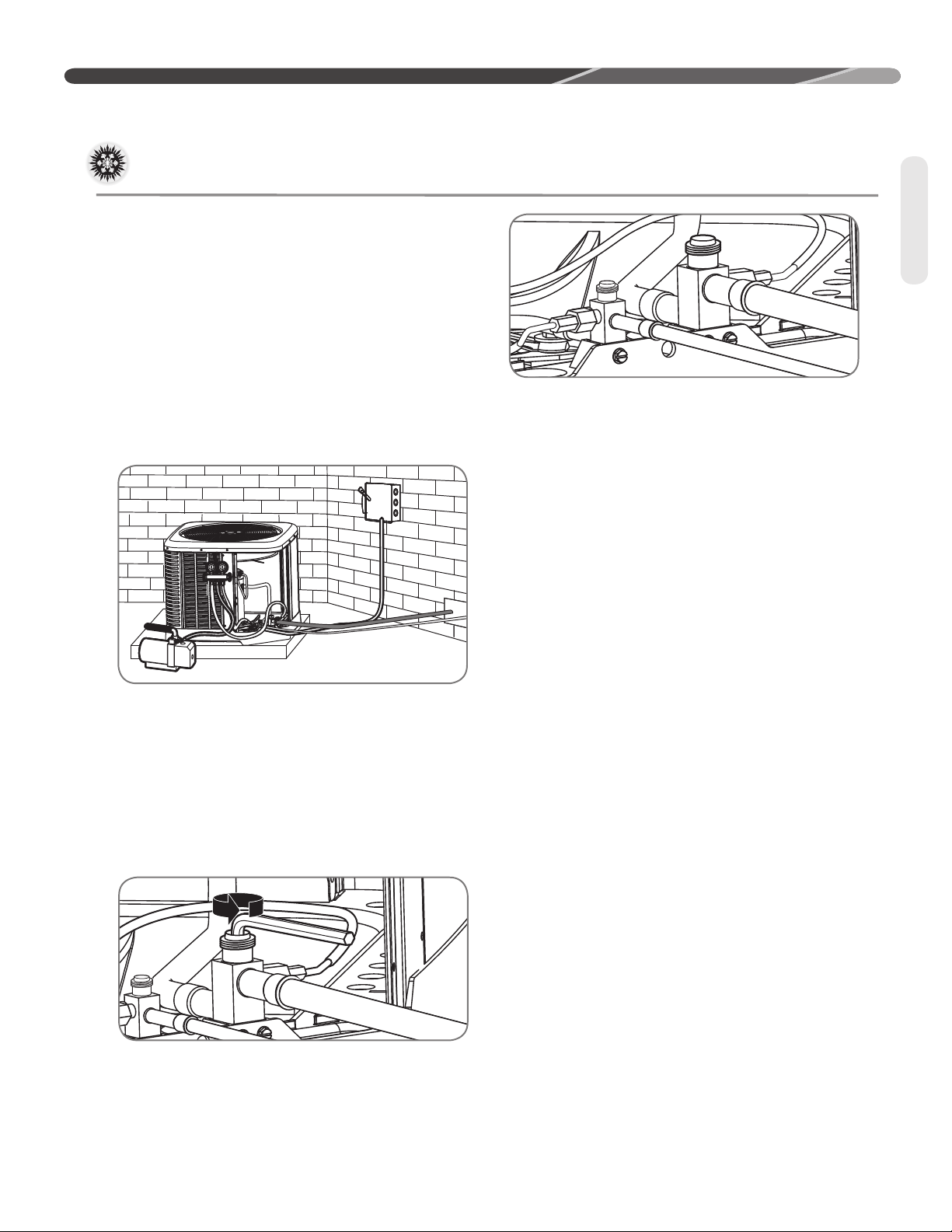
START-UP
ST-A1226-08-00
Evacuation and Leak Testing
Evacuation Procedure
Evacuation is the most important part of the entire
service procedure. The life and efficiency of the
equipment is dependent upon the thoroughness
exercised by the serviceman when evacuating air
and moisture from the system.
Air or nitrogen in the system causes high
condensing temperatures and pressure, resulting
in increased power input and nonverifiable
performance.
Moisture chemically reacts with the refrigerant and
oil to form corrosive hydrofluoric acid. This attacks
motor windings and parts, causing breakdown.
• After the system has been leak-checked and
proven sealed, connect the vacuum pump and
evacuate system to 500 microns and hold 500
microns or less for at least 15 minutes. The
vacuum pump must be connected to both the
high and low sides of the system by connecting
to the two pressure ports. Use the largest size
connections available since restrictive service
connections may lead to false readings because
of pressure drop through the fittings.
Evacuation
• Gauges must be connected at this point to
check and adjust charge. Do not replace caps
yet.
IMPORTANT: Compressors
(especially scroll type) should never be used to
evacuate the air conditioning system because
internal electrical arcing may result in a damaged
or failed compressor. Never run a scroll
compressor while the system is in a vacuum or
compressor failure will occur.
Final Leak Testing
After the unit has been properly evacuated and
service valves opened, a halogen leak detector
should be used to detect leaks in the system.
All piping within the condenser, evaporator, and
interconnecting tubing should be checked for
leaks. If a leak is detected, the refrigerant should
be recovered before repairing the leak. The Clean
Air Act prohibits releasing refrigerant into the
atmosphere.
• After adequate evacuation, open both service
valves by removing both brass service valve
caps with an adjustable wrench. Insert a 3/16"
[5 mm] or 5/16" [8 mm] hex wrench into the
stem and turn counterclockwise until the wrench
stops.
31
Page 32

START-UP
Checking Refrigerant Charge
Charge for all systems should be checked against
the Charging Chart inside the access panel cover.
compressor shell is hot. Touching the compressor
top may result in serious personal injury.
IMPORTANT: Use factory-approved
charging method as outlined on the next page to
Refrigerant
ensure proper system charge.
NOTICE: The optimum refrigerant charge
for any outdoor unit matched with an indoor
coil/air handler is affected by the application.
Therefore, charging data has been developed to
assist the field technician in optimizing the charge
for all mounting configurations (UF – Upflow, DF
– Downflow, LH – Left-Hand Discharge, and RH –
Right-Hand Discharge). Refer to the charging chart
inside the access panel cover on the unit and
choose the appropriate column for the specific
application being installed or serviced.
Charging Units With R-410A
Refrigerant
approximately 60% higher (1.6 times) than R-22
pressures. Use appropriate care when using this
refrigerant. Failure to exercise care may result in
equipment damage or personal injury.
Charge for all systems should be checked against
the Charging Chart inside the access panel cover.
IMPORTANT: Do not operate the
compressor without charge in the system.
Addition of R-410A will raise high-side pressures
(liquid and discharge).
NOTICE: System maintenance is to be
performed by a qualified and certified technician.
The following method is used for charging systems
in the cooling mode. All steps listed should be
performed to ensure proper charge has been set.
For measuring pressures, the service valve port
on the liquid valve (small valve) and suction valve
(large valve) are to be used
WARNING:
CAUTION:
The top of the scroll
R-410A pressures are
Supply airflow must be between 320 and 450 cfm
per rated cooling ton prior to adjusting system
charge. If a humidification system is installed,
disengage it from operation prior to charge
adjustment. Refer to the “Checking Airflow” section
of this manual for further instruction.
NOTICE: Verify system components
are matched according to the outdoor unit
Specification Sheet.
Measurement Device Setup
1. With an R-410A gauge set, attach the highpressure hose to the access fitting on the liquid
(small) service valve at the OD unit.
2.
Attach the low-pressure hose to the access fitting
on the suction (large) service valve.
3. Attach a temperature probe within 6" [15.2 cm]
outside of the unit on the copper liquid line
(small line). For more accurate measurements,
clean the copper line prior to measurement and
use a calibrated clamp-on temperature probe or
an insulated surface thermocouple.
Charging by Weight
NOTICE:
weight for the straight length of the refrigerant line set.
For a new installation, evacuation of inter-
connecting tubing and indoor coil is adequate;
otherwise, evacuate the entire system. Use the
factory charge shown in “Electrical and Physical
Data” on page 5 of these instructions or on the
unit data plate. Note that the charge value includes
charge required for 15 ft. [4.6 m] of standard-size
interconnecting liquid line without a filter drier.
Calculate actual charge required with installed
liquid line size and length using:
1/4" [6.4 mm] O.D. = .3 oz./ft. [8.5 g/.30 m]
5/16" [7.9 mm] O.D. = .4 oz./ft. [11.3 g/.30 m]
3/8" [9.5 mm] O.D. = .6 oz./ft. [17.0 g/.30 m]
1/2" [12.7 mm] O.D. = 1.2 oz./ft. [34.0 g/.30 m]
Add 6 oz. for field-installed filter drier.
Adjust the system charge by
Confirm ID Airflow and Coils
Are Clean
Confirm adequate indoor supply airflow prior to
starting the system. See the Technical Specification
Sheet for rated airflow for each ID/OD unit match.
Air filter(s) and coils (indoor and outdoor) are to be
clean and free of frost prior to starting the system.
32
Page 33

Checking Refrigerant Charge (cont.)
START-UP
With an accurate scale (+/– 1 oz. [28.3 g]) or
volumetric charging device, adjust charge
difference between that shown on the unit data
plate and that calculated for the new system
installation. If the entire system has been
evacuated, add the total calculated charge.
IMPORTANT: Charging by weight is
not always accurate since the application can
affect the optimum refrigerant charge. Charging by
weight is considered a starting point ONLY. Always
check the charge by using the Charging Chart
and adjust as necessary. CHARGING BY LIQUID
SUBCOOLING MUST BE USED FOR FINAL
CHARGE ADJUSTMENT.
With thermostat in the “Off” position, turn on
the power to the furnace or air handler and the
condensing unit. Start the condensing unit and the
furnace or air handler with the thermostat. Verify
that the outdoor unit is operating and the indoor
air mover is delivering the correct airflow for the
system size.
Gross Charging by Pressures
1. Following airflow verification and charge weighin, run the unit for a minimum of 15 minutes
prior to noting pressures and temperature.
IMPORTANT: Indoor conditions
as measured at the indoor coil must be within
2°F [1.1°C] of the following during gross charge
(pressure) evaluation:
Cooling Mode: 80°F [26.7°C] Dry Bulb
Heating Mode: 70°F [21.1°C] Dry Bulb
NOTICE:
or below this range, run the system to bring the
temperature down or run the electric heat/furnace
to bring the temperature within this range. System
pressure values provided in the Charging Chart for
outdoor dry bulbs corresponding to conditions outside
of these ranges are provided as reference ONLY.
If the Indoor temperature is above
2. Note the Outdoor Dry Bulb Temperature,
ODDB° = _____°F [_____°C]. Unit charging is
recommended under the following outdoor
conditions ONLY:
Cooling Mode ONLY: 55°F [12.8°C] outdoor dry
bulb and above
3. Locate and note the design pressures. The
correct liquid and vapor pressures are found at
the intersection of the installed system and the
outdoor ambient temperature on the Charging
Chart located inside the access panel cover.
Liquid Pressure: = ______psig; Vapor Pressure =
______psig
NOTICE:
are for gross charge check ONLY. These pressure
values are typical, but may vary due to application.
Evaporator load (indoor coil in cooling mode/outdoor
coil in heating mode) will cause pressures to deviate.
Note that all systems have unique pressure curves.
The variation in the slope and value is determined
by the component selection for that indoor/outdoor
matched system. The variation from system to
system seen in the table is normal. The values listed
are for the applicable indoor coil match ONLY!
4. If the measured liquid pressure is below the
listed requirement for the given outdoor and
indoor conditions, add charge. If the measured
liquid pressure is above the listed requirement
for the given outdoor and indoor conditions,
remove charge.
The refrigerant pressures provided
Final Charge by Subcooling
1. After gross charging, note the designed
subcooling value. The correct subcooling value
is found at the intersection of the installed
system and the outdoor ambient temperature
on the Charging Chart located inside the access
panel cover.
SC° from Charging Chart = _____°F [_____°C].
IMPORTANT: Indoor conditions as
measured at the indoor coil are required to be
between 70°F [21.1°C] and 80°F [26.7°C] dry
bulb for fine-tuned unit charge adjustment. Unit
charging is recommended under the following
outdoor conditions ONLY:
Cooling Mode ONLY: 55°F [12.8°C] outdoor dry
bulb and above
Refrigerant
33
Page 34

START-UP
Checking Refrigerant Charge (cont.)
NOTICE: If the indoor temperature is
above or below the recommended range, run the
system to bring the temperature down or run the
electric heat/furnace to bring the temperature
up. System subcooling values provided in
the Charging Chart for outdoor dry bulbs
corresponding to conditions outside of the above
range are provided as reference ONLY.
2. Note the measured Liquid Pressure, Pliq =
Refrigerant
3. Note the liquid line temperature, Liq° = _____°F
4.
5.
______psig, as measured from the liquid
(small) service valve. Use the Temperature
Pressure Chart below to note the corresponding
saturation temperature for R-410A at the
measured liquid pressure.
Liquid Saturation Temperature, SAT°= _____°F
[_____°C].
[_____°C], as measured from a temperature
probe located within 6" [15.2 cm] outside of
the unit on the copper liquid line (small line).
It is recommended to use a calibrated clampon temperature probe or an insulated surface
thermocouple.
Subtract the liquid line temperature from the
saturation temperature to calculate subcooling.
SAT°_____°F
SC°_____°F
Adjust charge to obtain the specified subcooling
value. If the measured subcool is below the listed
requirement for the given outdoor and indoor
[_____°C]
[_____°C]
- Liq°_____°F
[_____°C]
=
conditions, add charge. If the measured subcool
is above the listed requirement for the given
outdoor and indoor conditions, remove charge.
Finishing Up Installation
• Disconnect pressure gauges from pressure ports;
then replace the pressure port caps and tighten
adequately to seal caps. Do not overtighten.
• Replace the service valve caps finger-tight
and then tighten with an open-end wrench
adequately to seal caps. Do not overtighten.
• Replace control box cover and service panel and
install screws to secure service panel.
• Restore power to unit at disconnect if required.
• Configure indoor thermostat per the thermostat
installation instructions and set thermostat to
desired mode and temperature.
NOTICE: Systems should not be fine-
tune charged below 40°F [4.4°C] outdoor dry bulb.
IMPORTANT: Excessive use of
elbows in the refrigerant line set can produce
excessive pressure drop. Follow industry
best practices for installation. Installation
and commissioning of this equipment is to
be performed by trained and qualified HVAC
professionals. For technical assistance, contact
your Distributor Service Coordinator.
34
TEMPERATURE PRESSURE CHART
SATURATION
TEMP
(Deg. F) [Deg.
C]
-150 [-101]
-140 [-96]
-130 [-90]
-120 [-84]
-110 [-79]
-100 [-73]
-90 [-68]
-80 [-62]
-70 [-57]
-60 [-51] 0.4 15 [-9] 70.2 80 [27] 235.6 145 [63] 576.0
-50 [-46] 5.1 20 [-7] 78.5 85 [29] 254.5 150 [66] 612.8
-40 [-40] 10.9 25 [-4] 87.5 90 [32] 274.3
-35 [-37] 14.2 30 [-1] 97.2 95 [35] 295.3
R-410A
PSIG
– -30 [-34] 17.9 35 [2] 107.5 100 [38] 317.4
– -25 [-32] 22.0 40 [4] 118.5 105 [41] 340.6
– -20 [-29] 26.4 45 [7] 130.2 110 [43] 365.1
– -15 [-26] 31.3 50 [10] 142.7 115 [46] 390.9
– -10 [-23] 36.5 55 [13] 156.0 120 [49] 418.0
– -5 [-21] 42.2 60 [16] 170.1 125 [52] 446.5
–
–
–
SATURATION
TEMP
(Deg. F) [Deg.
C]
0 [-18] 48.4 65 [18] 185.1 130 [54] 476.5
5 [-15] 55.1 70 [21] 201.0 135 [57] 508.0
10 [-12] 62.4 75 [24] 217.8 140 [60] 541.2
R-410A
PSIG
SATURATION
TEMP
(Deg. F) [Deg.
C]
R-410A
PSIG
SATURATION
TEMP
(Deg. F) [Deg.
C]
R-410A
PSIG
Page 35

COMPONENTS AND CONTROLS
Compressor Crankcase Heat (CCH)
While scroll compressors usually do not require
crankcase heaters, there are instances when a
heater should be added. Refrigerant migration
during the off cycle can result in a noisy start up.
Add a crankcase heater to minimize refrigerant
migration and to help eliminate any start up noise
or bearing “wash out.”
NOTE: A crankcase heater should be installed if:
• The system charge exceeds the values listed in
the adjacent tables,
• The system is subject to low voltage variations,
or
MAXIMUM SYSTEM CHARGE VALUES
RA13
Model
Size
18AJ
24AJ
30AJ
36AJ
42AJ
48AJ
60AJ
36AC
42AC
48AC
60AC
36AD
42AD
48AD
60AD
48AY
60AY
Compressor
Model Number
ZP14KAE/ZP14K6E
ZP20KAE
ZP24K5E
ZP31K6E
ZP34K5E
ZP42K5E
ZP51K5E
ZP31K6E-TF5
ZP34K5E-TF5
ZP42K5E-TF5
ZP51K5E-TF5
ZP31K6E-TFD
ZP34K5E-TFD
ZP42K5E-TFD
ZP51K5E-TFD
ZP42K5E-TFE
ZP51K5E-TFE
Charge Limit
Without Crankcase
Heat (1 Phase)
9.6 lbs.
9.6 lbs.
9.6 lbs.
9.6 lbs.
12 lbs.
12 lbs.
12 lbs.
9.6 lbs.
12 lbs.
12 lbs.
12 lbs.
9.6 lbs.
12 lbs.
12 lbs.
12 lbs.
12 lbs.
12 lbs.
• When a low ambient control is used for system
operation below 55°F.
All heaters are located on the lower half of the
compressor shell. Its purpose is to drive refrigerant
from the compressor shell during long off cycles,
thus preventing damage to the compressor during
start-up.
At initial start-up or after extended shutdown
periods, make sure the heater is energized for at
least 12 hours before the compressor is started.
(Disconnect switch is on and wall thermostat is off.)
MAXIMUM SYSTEM CHARGE VALUES
RA14
Model
Size
18AJ
24AJ
30AJ
36AJ
42AJ
48AJ
60AJ
36AC
42AC
48AC
60AC
36AD
42AD
48AD
60AD
MAXIMUM SYSTEM CHARGE VALUES
RA14XXW
Model
Size
18WJ
24WJ
30WJ
36WJ
42WJ
36WC
42WC
MAXIMUM SYSTEM CHARGE VALUES
RA16
Model
Size
18AJ
24AJ
30AJ
36AJ
42AJ
48AJ
60AJ
60BJ
36AC
42AC
48AC
60AC
Compressor
Model Number
ZP14KAE/ZP14K6E
ZP20KAE
ZP24K5E
ZP29K5E
ZP34K5E
ZP39K5E
ZP49K6E
ZP31K6E-TF5
ZP34K5E-TF5
ZP42K5E-TF5
ZP51K5E-TF5
ZP31K6E-TFD
ZP34K5E-TFD
ZP42K5E-TFD
ZP51K5E-TFD
Compressor
Model Number
ZP14KAE
ZP20K6E
ZP24K6E
ZP31K6E
ZP34K6E
ZP31K6E-TF5
ZP34K5E-TF5
Compressor
Model Number
ZP14K6E
ZP21K6E
ZP24K6E
ZP31K6E
ZP34K6E
ZP38K6E
ZP49K6E
ZP49K6E
ZP31K6E-TF5
ZP34K6E-TF5
ZP38K6E-TF5
ZP49K6E-TF5
Charge Limit
Without Crankcase
Heat (1 Phase)
9.6 lbs.
9.6 lbs.
9.6 lbs.
9.6 lbs.
12 lbs.
12 lbs.
12 lbs.
9.6 lbs.
12 lbs.
12 lbs.
12 lbs.
9.6 lbs.
12 lbs.
12 lbs.
12 lbs.
Charge Limit
Without Crankcase
Heat (1 Phase)
9.6 lbs.
9.6 lbs.
9.6 lbs.
9.6 lbs.
12 lbs.
9.6 lbs.
12 lbs.
Charge Limit
Without Crankcase
Heat (1 Phase)
9.6 lbs.
9.6 lbs.
9.6 lbs.
9.6 lbs.
12 lbs.
12 lbs.
12 lbs.
12 lbs.
12 lbs.
12 lbs.
12 lbs.
12 lbs.
Components
35
Page 36

COMPONENTS AND CONTROLS
High- and Low-Pressure Controls (HPC and LPC)
Components
HPC and LPC are not installed on RA13**AJINA,
but can be field installed using the followiing
kit numbers: RXAB-A0z (high pressure control)
and RXAC-A0Z (low pressure control). These
controls keep the compressor from operating in
pressure ranges which can cause damage to the
compressor. Both controls are in the low-voltage
control circuit.
The high-pressure control (HPC) is an automaticreset which opens near 610 PSIG and closes near
420 PSIG.
The low-pressure control (LPC) is an automaticreset which opens near 15 PSIG and closes near
40 PSIG.
CAUTION: The compressor has
an internal overload protector. Under some
conditions, it can take up to 2 hours for this
overload to reset. Make sure overload has had
time to reset before condemning the compressor.
36
Page 37

ACCESSORIES
WARNING: Tur n off electric power
at the fuse box or service panel before making
any electrical connections. Also, the ground
connection must be completed before making line
voltage connections. Failure to do so can result in
electrical shock, severe personal injury, or death.
CAUTION:
SINGLE POLE COMPRESSOR
CONTACTOR (CC):
Single pole contactors are used on all singlephase units up through 5 tons. Caution must be
exercised when servicing as only one leg of the
power supply is broken with the contactor.
Hard Start Components
Start components are not usually required with
the scroll compressors used in RA13 condensing
units, but are available for special cases and
where start components are desirable to reduce
light dimming.
Time Delay Control
(Part No. RXMD-B01)
The time delay control is in the low voltage control
circuit. When the compressor shuts off due to a
power failure or thermostat operation, this control
keeps it off at least 5 minutes which allows the
system pressure to equalize, thus not damaging
the compressor or blowing fuses on start-up.
Low Ambient Control (LAC)
(Part No. RXAD-A08)
This component senses compressor head
pressure and shuts the heat pump fan off when
the head pressure drops to approximately 250
PSIG. This allows the unit to build a sufficient head
pressure at lower outdoor ambient (down to 0°F
[-18°C]) in order to maintain system balance and
obtain improved capacity. Low ambient control
should be used on all equipment operated below
70°F [21°C} ambient.
Accessories
37
Page 38

DIAGNOSTICS
NO
YES
Thermostat
Problem?
Transformer
Problem?
Go to Mechanical Checks
for Cooling or Heating
Hi Pressure Cut-Out
Hot Gas Sensor
Compressor
Time-Delay
Unit Wiring and
Connections
Start Capacitor
Potential Relay
Compressor Internal
Overload Open
Unit Wiring and
Connections
Compressor Winding
Open
Unit
Running?
YES
Repair and
Recheck
YES
Repair and
Recheck
NO
Voltage on Compressor
Side of Contactor?
NO
YES
Run Capacitor
NO
Voltage on Line
Side of Contactor?
NO
Circuit Breakers or
Fuses Open
YES
Compressor Winding
Grounded
Outdoor Fan Motor
Grounded
Grounded Capacitor
Replace Fuses or Reset
Breakers and Recheck
System
YES
Compressor
Contactor
NO
Unit Wiring and
Connections
Electrical Checks Flowchart
Diagnostics
38
Page 39

YES
NO
Pressure
Problems?
Low Liquid
Pressure
Low Suction
Pressure
High Head
Pressure
Go to Electrical
Checks Flowchart
Dirty Filters
Dirty Indoor Coil
Inadequate Indoor
Airow
Inoperative Indoor
Blower
Low on
Charge
Open IPR
Valv e
Low Ambient
Temperature
Bad
Compressor
Outdoor Check
Valve Closed
Restricted Indoor
Metering Device
Restricted
Filter Drier
Dirty Outdoor
Coil
Inoperative Outdoor
Fan
Overcharge
Recirculation of
Outdoor Air
Noncondensibles
Higher Than Ambient Air
Entering Outdoor Coil
Wrong Outdoor
Fan Rotation
Inadequate Ducts
Outdoor Check
Valve Closed
Restricted
Filter Drier
Outdoor Unit
Running?
Low on Charge
Restricted Indoor
Metering Device
Restriction in
System
Recirculation of
Indoor Air
Wrong Indoor
Blower Rotation
Cooling Mechanical Checks Flowchart
DIAGNOSTICS
Diagnostics
39
Page 40

DIAGNOSTICS
General Troubleshooting Chart
Diagnostics
WARNING:
Disconnect all power to
unit before servicing. Contactor may break only one
side. Failure to shut off power can cause electrical
shock resulting in personal injury or death.
SYMPTOM POSSIBLE CAUSE REMEDY
Unit will not run • Power off or loose electrical connection
• Thermostat out of calibration – set too high
• Defective control board
• Blown fuses/tripped breaker
• Transformer defective
• High-pressure control open
Low-pressure control open
• Miswiring of communications (communication
light on continuously)
Outdoor fan runs,
compressor doesn't
Insuffi cient cooling • Improperly sized unit
Compressor short
cycles
Registers sweat • Low indoor airfl ow • Increase speed of blower or reduce restriction.
High head, low vapor
pressures
High head, high
or normal vapor
pressure – Cooling
mode
Low head, high vapor
pressures
Low vapor, cool
compressor, iced
indoor coil
High vapor pressure • Excessive load
Fluctuating head and
vapor pressures
Gurgle or pulsing
noise at expansion
device or liquid line
• Run or start capacitor defective
• Contactor defective
• Loose connection
• Compressor stuck, grounded or open motor
winding, open internal overload.
• Low-voltage condition
• Improper indoor airfl ow
• Incorrect refrigerant charge
• Air, noncondensibles, or moisture in system
• Bad ID TXV
• Incorrect voltage
• Defective overload protector
• Refrigerant undercharge
• Restriction in liquid line, expansion device, or
fi lter drier
• Bad TXV
• Dirty outdoor coil
• Refrigerant overcharge
• Outdoor fan not running
• Air or noncondensibles in system
• Bad TXV
• Bad compressor
• Low indoor airfl ow
• Operating below 65°F outdoors
• Moisture in system
• Closed ID circuit
• Defective compressor
• TXV hunting
• Air or noncondensibles in system
• Air or noncondensibles in system • Recover refrigerant. Evacuate and recharge.
• Check for correct voltage at line voltage connections in
condensing unit.
• Reset.
• Check control board diagnostic codes.
• Replace fuses/reset breaker.
• Check wiring. Replace transformer.
• Reset. Also see high head pressure remedy. The highpressure control opens at 610 PSIG.
• Check communication wiring.
• Replace.
• Replace.
• Check for correct voltage at compressor. Check and
tighten all connections.
• Wait at least 3 hours for overload to reset. If still open,
replace the compressor.
• Add start kit components.
• Recalculate load.
• Check. Should be approximately 400 CFM per ton.
• Charge per procedure attached to unit service panel.
• Recover refrigerant. Evacuate and recharge. Add fi lter
drier.
• Replace TXV
• At compressor terminals, voltage must be ± 10% of
nameplate marking when unit is operating.
• Replace. Check for correct voltage.
• Add refrigerant.
Replace air fi lter.
• Remove or replace defective component.
• Replace TXV.
• Clean coil.
• Correct system charge.
• Repair or replace.
• Recover refrigerant. Evacuate and recharge.
• Replace TXV.
• Replace compressor.
• Increase speed of blower or reduce restriction.
Replace air fi lter.
• Add Low Ambient Kit.
• Recover refrigerant. Evacuate and recharge. Add fi lter
drier.
• Repair or replace ID coil
• Recheck load calculation.
• Replace.
• Check TXV bulb clamp. Check air distribution on coil.
Replace TXV.
• Recover refrigerant. Evacuate and recharge.
40
Page 41

DIAGNOSTICS
Service Analyzer Charts
COMPRESSOR OVERHEATING
SYMPTOM POSSIBLE CAUSE CHECK/REMEDY
High superheat
(greater than 15°F
[-9°C] at coil)
Low line voltage Loose wire connections Check wiring.
High line voltage Power company problem Have problem corrected.
Low charge Check system charge.
Faulty metering device Restricted cap tube, TEV (TXV)
Power element superheat out of adjustment internally
Foreign matter stopping fl ow
High internal load Hot air (attic) entering return
Heat source on; miswired or faulty control
Restriction in liquid line Drier plugged.
Line kinked.
Low head pressure Low charge
Operating in low ambient temperatures
Suction or liquid line subjected to high heat
source
Power company problem, transformer Have problem corrected before diagnosis continues.
Undersized wire feeding unit Correct and complete diagnosis.
Hot attic / insulate liquid line
Hot water line
High head
pressure
Short cycling of compressor
Overcharge Check system charge.
Dirty outdoor coil Clean coil.
Faulty or wrong size outdoor fan motor Replace fan motor.
Diagnostics
Faulty fan blade or wrong rotation Replace fan blade.
Replace with correct rotation motor.
Recirculation of air Correct installation.
Additional heat source Check for dryer vent near unit.
Check for recirculation from other equipment.
Noncondensibles Recover refrigerant. Evacuate and recharge system.
Equipment not matched Correct mismatch.
Faulty pressure control Replace pressure control.
Loose wiring Check unit wiring.
Thermostat Located in supply air stream
Diff erential setting too close
Customer misuse
TEV Internal foreign matter
Power element failure
Valve too small
Distributor tube/tubes restricted
Distributor tube Restricted with foreign matter
Kinked
I.D. reduced from previous compressor failure
41
Page 42

DIAGNOSTICS
Service Analyzer Charts
COMPRESSOR OVERHEATING (cont.)
SYMPTOM POSSIBLE CAUSE CHECK OR REMEDIES
Short cycling of
compressor (cont.)
Faulty Compressor
Valves
ELECTRICAL
Voltage present on
load side of compressor contactor
and compressor
won't run
Voltage present on
line side of compressor contactor
only
Diagnostics
No voltage on line
side of compressor
contactor
SYMPTOM POSSIBLE CAUSE CHECK OR REMEDIES
Low charge Check system charge.
Low evaporator airfl ow Dirty coil
Faulty run capacitor Replace.
Faulty internal overload Replace compressor.
Fast equalization/Low pressure diff erence Replace compressor and examine system to
Compressor start components Check start capacitor.
Run capacitor Check with ohmmeter
Internal overload Allow time to reset.
Compressor windings Check for correct ohms.
Thermostat Check for control voltage to contactor coil.
Compressor control circuit High-pressure switch
Blown fuses or tripped circuit breaker Check for short in wiring or unit.
Improper wiring Recheck wiring diagram.
Dirty fi lter
Duct too small or restricted
locate reason.
Check potential relay.
Low-pressure switch
Ambient thermostat
Solid-state protection control or internal thermal sensors
Compressor timed off /on control or interlock
Improper voltage High voltage Wrong unit
Low voltage Wrong unit
Single Phasing (3 phase) Check incoming power and fusing.
FLOODED STARTS
SYMPTOM POSSIBLE CAUSE CHECK OR REMEDIES
Liquid in the compressor shell
Too much liquid in
system
Faulty or missing crankcase heater Replace crankcase heater.
Incorrect piping Check piping guidelines.
Overcharge Check and adjust charge.
42
Power supply problem
Power supply problem
Wiring undersized
Loose connections
Page 43

DIAGNOSTICS
Service Analyzer Charts
CONTAMINATION
SYMPTOM POSSIBLE CAUSE REMEDY
Moisture Poor evacuation on installation or during service In each case, the cure is the same. Recover refrigerant.
High head pressure Noncondensibles air
Unusual head and
suction readings
Foreign matter –
copper fi lings
Copper oxide Dirty copper piping or nitrogen not used when
Welding scale Nitrogen not used during brazing
Soldering fl ux Adding fl ux before seating copper partway
Excess soft solder Wrong solder material
Wrong refrigerant or mixed refrigerants
Copper tubing cuttings
brazing
LOSS OF LUBRICATION
SYMPTOM POSSIBLE CAUSE REMEDY
Compressor failures Line tubing too large Reduce pipe size to improve oil return.
Low suction pressure Low charge Check system charge.
Refrigerant leaks Repair and recharge.
Cold, noisy
compressor –
Slugging
Noisy compressor Migration Check crankcase heater.
Cold, sweating
compressor
Low load Reduced airfl ow Dirty fi lter
Short cycling of
compressor
Dilution of oil with refrigerant Observe piping guidelines.
Flooding Check system charge.
Thermostat setting Advise customer.
Faulty high- or low-pressure control Replace control.
Loose wiring Check all control wires.
Thermostat In supply air stream, out of calibration
SLUGGING
SYMPTOM POSSIBLE CAUSE REMEDY
On start-up Incorrect piping Review pipe size guidelines.
TEV hunting when
running
Faulty TEV Replace TEV.
Add fi lter drier, evacuate, and recharge.
Dirty coil
Wrong duct size
Restricted duct
Customer misuse
Diagnostics
43
Page 44

DIAGNOSTICS
Service Analyzer Charts
FLOODING
SYMPTOM POSSIBLE CAUSE REMEDY
Loose sensing bulb Secure the bulb and insulate.
Poor system control
using a TEV
THERMOSTATIC EXPANSION VALVES
SYMPTOM POSSIBLE CAUSE REMEDY
High Superheat, Low
Suction Pressure
(superheat over
15°F [-9°C])
Diagnostics
Valve feeds too much
refrigerant, with low
superheat and higher
than normal suction
pressure
Bulb in wrong location Relocate bulb.
Wrong size TEV Use correct replacement.
Improper superheat setting (less than 5°F [-15°C])
Moisture freezing and blocking valve Recover charge, install fi lter-drier, evacuate system,
Dirt or foreign material blocking valve Recover charge, install fi lter-drier, evacuate system,
Low refrigerant charge Correct the charge.
Vapor bubbles in liquid line Remove restriction in liquid line. Correct the refrigerant
Misapplication of internally equalized valve Use correct TEV.
Plugged external equalizer line Remove external equalizer line restriction.
Undersized TEV Replace with correct valve.
Loss of charge from power head sensing bulb Replace power head or complete TEV.
Charge migration from sensing bulb to power
head (Warm power head with warm, wet cloth.
Does valve operate correctly now?)
Moisture causing valve to stick open. Recover refrigerant, replace fi lter-drier, evacuate system,
Dirt or foreign material causing valve to stick
open
TEV seat leak (a gurgling or hissing sound is
heard AT THE TEV during the off cycle, if this is
the cause). NOT APPLICABLE TO BLEED PORT
VALVES.
Oversized TEV Install correct TEV.
Incorrect sensing bulb location Install bulb with two mounting straps, in 2:00 or 4:00
Low superheat adjustment Replace TEV.
Incorrectly installed, or restricted external
equalizer line
Replace TEV.
recharge.
recharge.
charge.
Remove noncondensible gases.
Size liquid line correctly.
Ensure TEV is warmer than sensing bulb.
and recharge.
Recover refrigerant, replace fi lter drier, evacuate system,
and recharge.
Replace the TEV.
position on suction line, with insulation.
Remove restriction, or relocate external equalizer.
44
Page 45

DIAGNOSTICS
Service Analyzer Charts
THERMOSTATIC EXPANSION VALVES (cont.)
SYMPTOM POSSIBLE CAUSE REMEDY
Refrigerant drainage from fl ooded evaporator Install trap riser to the top of the evaporator coil.
Compressor fl ood
back upon start-up
Superheat is low to
normal with low
suction pressure
Superheat and
suction pressure
fl uctuate (valve is
hunting)
Valve does not
regulate at all
Inoperable crankcase heater or crankcase heater
needed
Any of the causes listed under symptoms of
Electrical problems on page 45
Unequal evaporator circuit loading Ensure airfl ow is equally distributed through evaporator.
Low load or airfl ow entering evaporator coil Ensure blower is moving proper air CFM.
Expansion valve is oversized Install correct TEV.
Sensing bulb is aff ected by liquid refrigerant or
refrigerant oil fl owing through suction line
Unequal refrigerant fl ow through evaporator
circuits
Moisture freezing and partially blocking TEV Recover refrigerant, change fi lter-drier, evacuate system,
External equalizer line not connected or line
plugged
Sensing bulb lost its operating charge Replace TEV.
Valve body damaged during soldering or by
improper installation
Replace or add crankcase heater.
Any of the solutions listed under solutions of Electrical
problems on page 45
Check for blocked distributor tubes.
Remove/Correct any airfl ow restriction.
Relocate sensing bulb in another position around the
circumference of the suction line.
Ensure sensing bulb is located properly.
Check for blocked distributor tubes.
and recharge.
Connect equalizer line in proper location, or remove any
blockage.
Replace TEV.
Diagnostics
45
Page 46

DIAGNOSTICS
SYSTEM
PROBLEM
Overcharge
Undercharge
Liquid Restriction
(Drier)
Low Indoor Airfl ow
Dirty Outdoor Coil
Low Outdoor
Ambient Temperature
Ineffi cient
Compressor
Indoor TXV Feeler
Bulb Charge Lost
Poorly Insulated
Indoor Sensing Bulb
DISCHARGE
PRESSURE
High High Low High High
Low Low High Low Low
Low Low High High Low
Low Low Low Low Low
High High Low Low High
Low Low High High Low
Low High High High Low
Low Low High High Low
High High Low Low High
COOLING MODE
TROUBLESHOOTING TIPS
INDICATORS
SUCTION
PRESSURE
SUPERHEAT
Normal: 5°–15°F
[-15° – -9°C]
SUBCOOLING
Normal: See
Charging Chart
COMPRESSOR
AMPS
Diagnostics
46
Page 47

For Single-Phase Models
WIRING DIAGRAMS
Wiring Diagrams
47
Page 48

WIRING DIAGRAMS
For Three-Phase Models
Wiring Diagrams
48
 Loading...