

Page 1

Rheem Classic®Series
Air Conditioners
FORM NO. A11-221 REV. 1
• New composite base pan – dampens sound, captures louver
panels, eliminates corrosion and reduces number of fasteners
needed
• Powder coat paint system – for a long lasting professional finish
• Scroll compressor – uses 70% fewer moving parts for higher
efficiency and increased reliability
• Modern cabinet aesthetics – increased curb appeal with visually appealing design
• Curved louver panels – provide ultimate coil protection,
enhance cabinet strength, and increased cabinet rigidity
• Optimized fan orifice – optimizes airflow and reduces unit
sound
• Rust resistant screws – confirmed through 1500-hour salt
spray testing
• PlusOne™ Expanded Valve Space – 3"-4"-5" service valve
space – provides a minimum working area of 27-square
inches for easier access
• PlusOne™ Triple Service Access – 15" wide, industry lead-
ing corner service access – makes repairs easier and faster.
The two fastener removable corner allows optimal access to
internal unit components. Individual louver panels come out
once fastener is removed, for faster coil cleaning and easier
cabinet reassembly
• Diagnostic service window with two-fastener opening –
provides access to the high and low pressure.
• External gauge port access – allows easy connection of
“low-loss” gauge ports
• Single-row condenser coil – makes unit lighter and allows
thorough coil cleaning to maintain “out of the box”
performance
• 35% fewer cabinet fasteners and fastener-free base – allow
for faster access to internal components and hassle-free
panel removal
• Service trays – hold fasteners or caps during service calls
• QR code – provides technical information on demand for
faster service calls
• Fan motor harness with extra long wires allows unit top to be
removed without disconnecting fan wire.
Air
Air Conditioners
RA13 Series
“Proper sizing and installation of equipment is critical to achieve
optimal performance. Ask your Dealer for details or visit
www.energystar.gov.”
RA13 Series
Efficiencies 13-15.5 SEER/11.5-13 EER
Nominal Sizes 1
1
/2 to 5 Ton [5.28 to 17.6 kW]
Cooling Capacities 17.3 to 60.5 kBTU
[5.7 to 17.7 kW]
15.5
Page 2

Air
Table of Contents
RA13 Series
2
TABLE OF CONTENTS
Standard Feature ......................................................................................................3
Available SKUs ........................................................................................................3
Features & Benefits ..............................................................................................4-5
Model Number Identification ................................................................................6-7
General Data/Electrical Data ....................................................................................8
Accessories ............................................................................................................9
Weighted Sound Power............................................................................................9
Thermostats..............................................................................................................9
Unit Dimensions......................................................................................................10
Clearances..............................................................................................................11
Wiring Diagrams ....................................................................................................12
Application Guidelines ............................................................................................12
Refrigerant Line Size Information ......................................................................13-14
Performance Data ............................................................................................15-40
Guide Specifications ..............................................................................................41
Limited Warranty ....................................................................................................42
Page 3
Air
Standard Feature/Available SKUs
RA13 Series
3
STANDARD FEATURES
Feature 18 24 30 36 42 48 60
R-410a Refrigerant √ √ √ √ √ √ √
Maximum SEER 15.1 15.0 15.5 15.1 14.5 14.5 14.0
Maximum EER 12.5 12.5 13.0 12.5 12.0 12.0 11.5
Scroll Compressor √ √ √ √ √ √ √
Field Installed Filter Drier √ √ √ √ √ √ √
Front Seating Service Valves √ √ √ √ √ √ √
Internal Pressure Relief Valve √ √ √ √ √ √ √
Internal Thermal Overload √ √ √ √ √ √ √
Long Line capability √ √ √ √ √ √ √
Low Ambient capability with Kit √ √ √ √ √ √ √
3-4-5 Expanded Valve Space √ √ √ √ √ √ √
Composite Basepan √ √ √ √ √ √ √
2 Screw Control Box Access √ √ √ √ √ √ √
15" Access to Internal Components √ √ √ √ √ √ √
Quick release louver panel design √ √ √ √ √ √ √
No fasteners to remove along bottom √ √ √ √ √ √ √
Optimized Venturi Airflow √ √ √ √ √ √ √
Single row condenser coil √ √ √ √ √ √ √
Powder coated paint √ √ √ √ √ √ √
Rust resistant screws √ √ √ √ √ √ √
QR code √ √ √ √ √ √ √
External gauge ports √ √ √ √ √ √ √
Service trays √ √ √ √ √ √ √
√ = Standard
Standard Feature Table
Available SKUs
Available Models Description
RA1318AJ1NA
Classic
®
Series 1 1/2 ton 13 SEER Single-Stage Air Conditioner-208/230/1/60
RA1324AJ1NA
Classic
®
Series 2 ton 13 SEER Single-Stage Air Conditioner-208/230/1/60
RA1330AJ1NA
Classic
®
Series 2 1/2 ton 13 SEER Single-Stage Air Conditioner-208/230/1/60
RA1336AJ1NA
Classic
®
Series 3 ton 13 SEER Single-Stage Air Conditioner-208/230/1/60
RA1342AJ1NA
Classic
®
Series 3 1/2 ton 13 SEER Single-Stage Air Conditioner-208/230/1/60
RA1348AJ1NA
Classic
®
Series 4 ton 13 SEER Single-Stage Air Conditioner-208/230/1/60
RA1360AJ1NA
Classic
®
Series 5 ton 13 SEER Single-Stage Air Conditioner-208/230/1/60
RA1318AJ1NB
Classic
®
Series 1 1/2 ton 13 SEER Single-Stage Air Conditioner w/ High/Low Pressure-208/230/1/60
RA1324AJ1NB
Classic
®
Series 2 ton 13 SEER Single-Stage Air Conditioner w/ High/Low Pressure-208/230/1/60
RA1330AJ1NB
Classic
®
Series 2 1/2 ton 13 SEER Single-Stage Air Conditioner w/ High/Low Pressure-208/230/1/60
RA1336AJ1NB
Classic
®
Series 3 ton 13 SEER Single-Stage Air Conditioner w/ High/Low Pressure-208/230/1/60
RA1342AJ1NB
Classic
®
Series 3 1/2 ton 13 SEER Single-Stage Air Conditioner w/ High/Low Pressure-208/230/1/60
RA1348AJ1NB
Classic
®
Series 4 ton 13 SEER Single-Stage Air Conditioner w/ High/Low Pressure-208/230/1/60
RA1360AJ1NB
Classic
®
Series 5 ton 13 SEER Single-Stage Air Conditioner w/ High/Low Pressure-208/230/1/60
RA1336AC1NB
Classic
®
Series 3 ton 13 SEER Single-Stage Air Conditioner w/ High/Low Pressure-208/230/3/60
RA1342AC1NB
Classic
®
Series 3 1/2 ton 13 SEER Single-Stage Air Conditioner w/ High/Low Pressure-208/230/3/60
RA1348AC1NB
Classic
®
Series 4 ton 13 SEER Single-Stage Air Conditioner w/ High/Low Pressure-208/230/3/60
RA1360AC1NB
Classic
®
Series 5 ton 13 SEER Single-Stage Air Conditioner w/ High/Low Pressure-208/230/3/60
RA1336AD1NB
Classic
®
Series 3 ton 13 SEER Single-Stage Air Conditioner w/ High/Low Pressure-460/3/60
RA1342AD1NB
Classic
®
Series 3 1/2 ton 13 SEER Single-Stage Air Conditioner w/ High/Low Pressure-460/3/60
RA1348AD1NB
Classic
®
Series 4 ton 13 SEER Single-Stage Air Conditioner w/ High/Low Pressure-460/3/60
RA1360AD1NB
Classic
®
Series 5 ton 13 SEER Single-Stage Air Conditioner w/ High/Low Pressure-460/3/60
Page 4

The RA13 is our 13 SEER air conditioner and is part of the
Rheem air conditioner product line that extends from 13 to 20
SEER. This highly featured and reliable air conditioner is
designed for years of reliable, efficient operation when matched
with Rheem indoor aluminum evaporator coils and furnaces or
air handler units with aluminum evaporators.
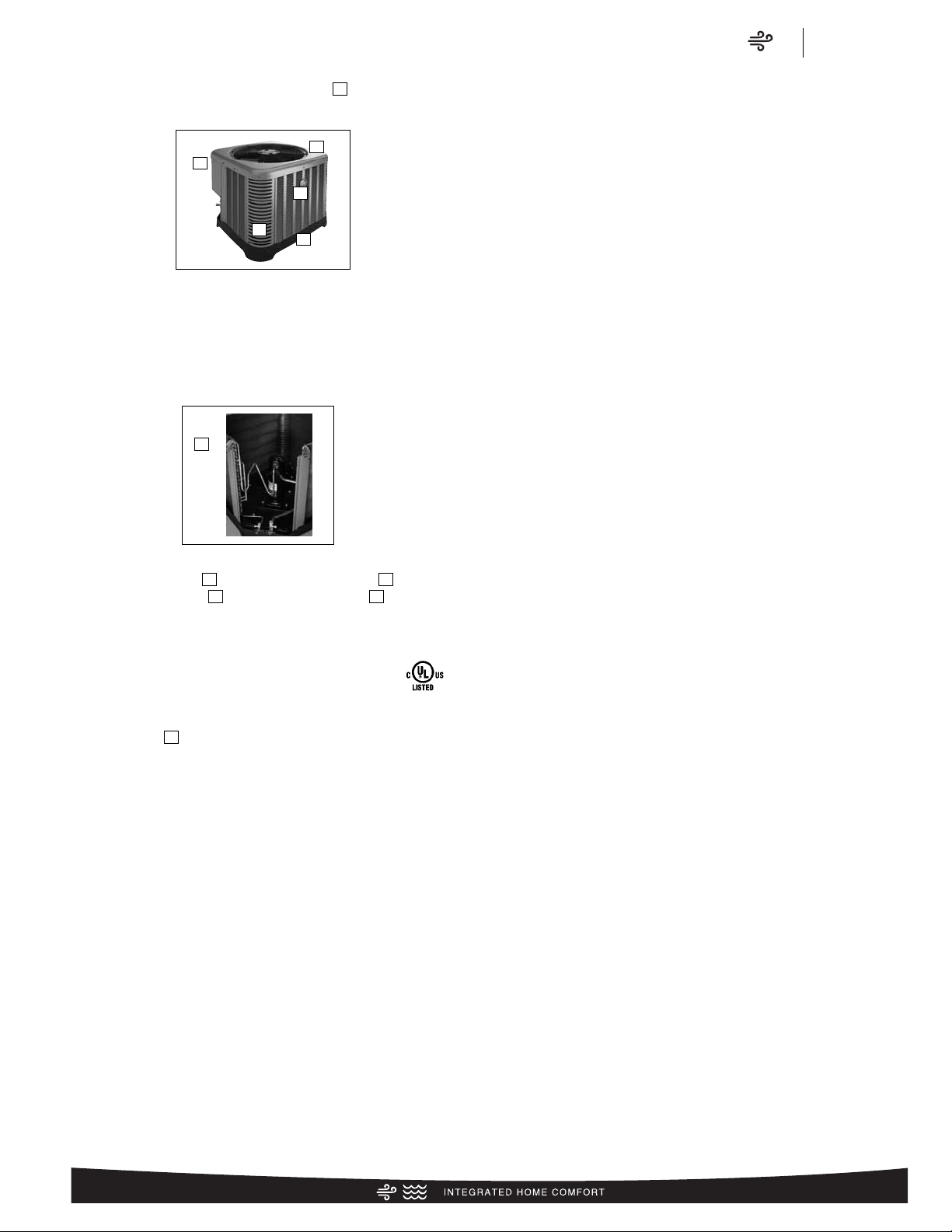
Our unique composite base ( ) reduces sound emission, eliminates rattles, significantly reduces fasteners, eliminates corrosion and has integrated brass compressor attachment inserts
()
. Furthermore it has incorporated into the design, water
management features, means for hand placement
()
for unit
maneuvering, screw trays
()
and inserts for lifting off unit
pad. ( )
Service Valves ( ) are rigidly mounted in the composite base
with 3" between suction and discharge valves, 4" clearance
below service valves and a minimum of 5" above the service
valves, creating industry leading installation ease. The minimum
27 square-inches around the service valves allows ample room
to remove service valve schrader prior to brazing, plenty of
clearance for easy brazing of the suction and discharge lines to
service valve outlets, easy access and hookup of low loss refrigerant gauges ( ), and access to the service valve caps for
opening. For applications with long-line lengths up to 250 feet
total equivalent length, up to 200 feet condenser above evaporator, or up to 80 feet evaporator above condenser, the long-line
instructions in the installation manual should be followed.
Controls are accessed from the corner of the unit by removing
only two fasteners from the control access cover, revealing the
industry’s largest 15" wide and 14" tall control area
()
. With all
this room in the control area the high voltage electrical whip ( )
can easily be inserted through the right size opening in the bottom of the control area. Routing it leads directly to contractor
lugs for connection. The low voltage control wires
()
are easily
connected to units low voltage wiring. If contactor or capacitor
( ) needs to be replaced there is more than adequate space to
make the repair. Furthermore, if high pressure and low pressure
model was not purchased but is desired to be installed in the
field, the service window ( ) can be removed by removing two
screws, to access the high and low side schrader fittings for easy
field installation. The entire corner can be removed providing
ultimate access to install the high and low pressure switch.
()
If in the rare event, greater access is needed to internal components, such as the compressor, the entire corner of the unit can
be removed along with the top cover assembly to have unprecedented access to interior of the unit
()
. Extra wire length is
incorporated into each outdoor fan and compressor so top
cover and control panel can be positioned next to the unit. With
minimal effort the plug can be removed from the compressor
and the outdoor fan wires can be removed from the capacitor to
allow even more uncluttered access to the interior of the unit
()
.
Outdoor coil heights range from as short as 22" to 28", aiding
access to the compressor. Disassembly to this degree and complete reassembly only takes a first time service technician less
than 10 minutes. ( )
All units utilize strong formed louver panels which provide industry leading coil protection. Louver removal for coil cleaning is
accomplished by removing one screw and lifting the panel out of
the composite base pan.
()
All RA13 units utilize single row
coils ( ) making cleaning easy and complete, restoring the
performance of the air conditioner back to out of the box performance levels year after year.
The outdoor fan motor has sleeve bearings and is inherently
protected. The motor is totally enclosed for maximum protection
from weather, dust and corrosion. Access to the outdoor fan is
made by removing four fasteners from the fan grille. The outdoor
fan can be removed from the fan grille by removing 4 fasteners
in the rare case outdoor fan motor fails.
Each cabinet has optimized composite ( ) fan orifice assuring
efficient and quiet airflow.
1
2
3
4
7
8
9
10
12
13
6
11
5
14
15
15
17
16
19
Air
Features & Benefits
RA13 Series
4
Introduction to RA13 Air Conditioner
1
4
6
4
3 5
2
8
11
9
10
13
12
16
14
18
15
19
7
17
Page 5
Air
Features & Benefits
RA13 Series
5
The entire cabinet has powder post paint ( ) achieving 1000
hour salt spray rating, allowing the cabinet to retain its aesthetics
throughout its life.
Scroll compressors with standard internal pressure relief and
internal thermal overload are used on all capacities assuring
longevity of high efficient and quiet operation for the life of the
product.
Each unit is shipped with filter drier for field installation and will
trap any moisture or dirt that could contaminate the refrigerant
system.
All cabinets have industry leading structural strength due to the
composite base pan
()
, interlocking corner post ( )
, formed
curved louver panels ( ) and drawn top cover ( ) making it
the most durable cabinet on the market today.
Each RA13 capacity has undergone rigorous psychometric testing to assure performance ratings of capacity, SEER
and EER per AHRI Standard 210/240 rating conditions. Also each unit bears the UL mark and each unit
is certified to UL 1995 safety standards.
Each unit has undergone specific strain and modal testing to
assure tubing
()
is outside the units natural frequency and that
the suction and discharge lines connected to the compressor
withstand any starting, steady state operation or shut down
forces imposed by the compressor.
All units have been sound tested in sound chamber to AHRI 270
rating conditions, and A-weighted Sound Power Level tables
produced, assuring units have acceptable noise qualities (see
page 9). Each unit has been ran in cooling operation at 95°F
and 82°F and sound ratings for the RA13 range from as low as
73 dBA to 79 dBA.
All units have been ship tested to assure units meet stringent
“over the road” shipping conditions.
As manufactured all units in the RA13 family have cooling capability to 55 °F. Addition of low ambient control will allow the unit
to operate down to 0°F. Factory testing is performed on each
unit. All component parts meet well defined specification and
continually go through receiving inspections. Each component
installed on a unit is scanned, assuring correct component utilization for a given unit capacity and voltage. All condenser coils
are leak tested with pressurization test to 550#’s and once
installed and assembled, each units’ complete refrigerant
system is helium leak tested. All units are fully charged from the
factory for up to 15 feet of piping. All units are factory run tested.
The RA13 has a 10-year conditional compressor and parts warranty (registration required).
Optional Accessories
(Refer to accessory chart for model #)
Compressor Crankcase Heater
Protects against refrigerant migration that can occur during low
ambient operation
Compressor Sound Cover
• Reinforced vinyl compressor cover containing a 1½ inch thick
batt of fiberglass insulation
• Open edges are sealed with a one-inch wide hook and loop
fastening tape
Compressor Hard Start Kit
• Single-phase units are equipped with a PSC compressor
motor, this type of motor normally does not need a potential
relay and start capacitor
• Kit may be required to increase the compressor starting
torque, in conditions such as low voltage
Low Ambient Kit
• Air conditioners operate satisfactorily in the cooling mode
down to 55°F outdoor air temperature without any additional
controls
• This Kit can be added in the field enabling unit to operate
properly down to 0° in the cooling mode
• Crankcase heater and freezestat should be installed on compressors equipped with a low ambient kit
3"/6"/12"
• Gray high density polyethylene feet are available to raise unit
off of mounting surface away from moisture
Low Pressure
• Can be added in field enabling the unit to shut off compressor
on loss of charge
NOTE: Unit can be purchased with high and low pressure
installed at factory. (Refer to SKU list)
High Pressure
• Can be added in field enabling unit to shut off compressor if
unit loses outdoor fan operation.
NOTE: Unit can be purchased with high and low pressure
installed at factory. (Refer to SKU list)
Decorative Top
• Can be installed on fan grille
25
20
2221
2423
20
24
23
22
21
25
Page 6
R
A 13 24 A
J
1 N A *
Brand Product
Category
SEER Capacity
BTU/HR
Major Series* Voltage Type Controls Minor Series** Option
Code
Rheem A - Air Conditioners
13 - 13 SEER
14 - 14 SEER
16 - 16 SEER
17 - 17 SEER
20 - 20 SEER
18 - 18,000 [5.28 kW]
24 - 24,000 [7.03 kW]
30 - 30,000 [8.79 kW]
36 - 36,000 [10.55 kW]
42 - 42,000 [12.31 kW]
48 - 48,000 [14.07 kW]
60 - 60,000 [17.58 kW]
A - 1st Design
J - 1ph, 208-230/60
C - 3ph, 208-230/60
D - 3ph, 460/60
1 - Single-stage
2 - Two-stage
V - Inverter
C - Communicating
N - Non-Communicating
A - 1st Design N/A
R
P 14 24 A
J
1 N A *
Brand Product
Category
SEER Capacity
BTU/HR
Major Series* Voltage Type Controls Minor Series** Option
Code
Rheem P - Heat Pump
13 - 13 SEER
14 - 14 SEER
15 - 15 SEER
17 - 17 SEER
20 - 20 SEER
18 - 18,000 [5.28 kW]
24 - 24,000 [7.03 kW]
30 - 30,000 [8.79 kW]
36 - 36,000 [10.55 kW]
42 - 42,000 [12.31 kW]
48 - 48,000 [14.07 kW]
60 - 60,000 [17.58 kW]
A - 1st Design
J - 1ph, 208-230/60
C - 3ph, 208-230/60
D - 3ph, 460/60
1 - Single-stage
2 - Two-stage
V - Inverter
P - Piston
C - Communicating
N - Non-Communicating
A - 1st Design N/A
R
C F 24 17
S
T A M C A *
Brand Product
Category
Type Capacity
BTU/HR
Width Efficiency Metering
Device
Major
Series*
Orientation Casing Minor Series** Option
Code
Rheem
C - Evap Coil F - Furn Coil
H - Air-Handler
Coil
24 - 24,000 [7.03 kW]
36 - 36,000 [10.55 kW]
48 - 48,000 [14.07 kW]
60 - 60,000 [17.58 kW]
14 - 14"
17 - 17.5"
21 - 21"
24 - 24.5"
S- Standard Eff.
M- Mid Eff.
H- High Eff.
T-TXV
E-EEV
P-Piston
A - 1st Design M - Multipoise
V - Vertical only/
convertible
H - Ded.
Horizontal only
C - Cased
U - Uncased
A - 1st Design N/A
Air
Model Number Identification
RA13 Series
6
Heat Pumps (For Reference)
Furnace Coils (For Reference)
Air Conditioners
[ ] Designates Metric Conversions
Page 7

R
96 V A
70
2 3 17 M S A
Brand Series Motor Major Rev Input
BTU/HR
Stages Air Flow Cabinet
Width
Configuration Nox Minor Rev
Rheem
90 - 90 AFUE
92 - 92 AFUE
95 - 95 AFUE
96 - 96 AFUE
97 - 97 AFUE
V - Variable speed
T - Constant
Torque
(X-13)
P - PSC
A - 1st Design
040 - 42,000 [12.31 kW]
060 - 56,000 [16.41 kW]
070 - 70,000 [20.51 kW]
085 - 84,000 [24.62 kW]
100 - 98,000 [28.72 kW]
115 - 112,000 [32.82 kW]
1 - Single-stage
2 - Two-stage
M - Modulating
3 - up to 3 ton
5 - 3 1/2 up to 5 ton
14 - 14"
17 - 17.5"
21 - 21"
24 - 24.5"
M - Multi X - Low Nox
S - Standard
A - 1st Design
Air
Model Number Identification
RA13 Series
7
R
80 2 V A
075
3 17 M S A
Brand Series Stages Motor Major Rev Input
BTU/HR
Air Flow Cabinet
Width
Configuration Nox Minor Rev
Rheem
80 - 80+ AFUE 1 - Single-stage
2 - Two-stage
V - Variable speed
T - Constant Torque (X-13)
P - PSC premium
S - PSC standard
A - 1st Design
050 - 50,000 [15 kW]
075 - 75,000 [22 kW]
100 - 100,000 [29 kW]
125 - 125,000 [37 kW]
150 - 150,000 [44 kW]
3 - up to 3 ton
4 - 2 1/2 to 4 ton
5 - 3 1/2 up to 5 ton
14 - 14"
17 - 17.5"
21 - 21"
24 - 24.5"
M - Multi
D - Down
Z - Down &
zero clearance
down flow
X - Low Nox
S - Standard
A - 1st Design
R
H 1 T 36
17
S T A N A A 000 *
Brand Product
Category
Stages of
Airflow
Motor Type Capacity
BTU/HR
Width Coil Size Metering
Device
Major
Series*
Controls Voltage Minor
Series**
Factory Heat
Cap
Option
Code
Rheem
H - Air
Handler
1 - Single-Stage
2 - Two-Stage
M - Modulating
V - Variable
Speed
T - Constant
Torque
P - PSC
24 - 24,000 [7.03 kW]
36 - 36,000 [10.55 kW]
48 - 48,000 [14.07 kW]
60 - 60,000 [17.58 kW]
14 - 14"
17 - 17.5"
21 - 21"
24 - 24.5"
S - Standard
Eff.
M -Mid Eff.
H - High Eff.
T - TEV
E - EEV
P - Piston
A - 1st Design C -Communicating
N -Non-comm
A - 1ph, 115/60
J - 1ph, 208-240/60
D - 3ph, 480/60
A - 1st Design 00 - no
factory heat
with option
code
*TBD
90%+ AFUE Gas Furnaces (For Reference)
80% AFUE Gas Furnaces (For Reference)
Air Handlers (For Reference)
[ ] Designates Metric Conversions
Page 8
Air
General Data/Electrical Data
RA13 Series
8
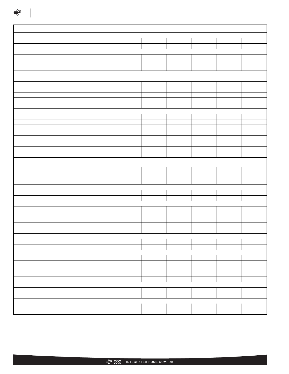
Physical Data
PHYSICAL DATA
Model No. RA1318A RA1324A RA1330A RA1336A RA1342A RA1348A RA1360A
Nominal Tonnage 1.5 2.0 2.5 3.0 3.5 4.0 5.0
Valve Connections
Liquid Line O.D. – in. 3/8 3/8 3/8 3/8 3/8 3/8 3/8
Suction Line O.D. – in. 3/4 3/4 3/4 3/4 7/8 7/8 7/8
Refrigerant (R410A) furnished oz.¹ 56 66 78 92 111 112 154
Compressor Type Scroll
Outdoor Coil
Net face area – Outer Coil 5.9 9.1 9.1 12.1 14.2 14.8 18.8
Net face area – Inner Coil — — — — — — —
Tube diameter – in. 3/8 3/8 3/8 3/8 3/8 3/8 3/8
Number of rows 1 1 1 1 1 1 1
Fins per inch 22 18 22 22 22 22 22
Outdoor Fan
Diameter – in. 20 20 20 20 20 24 26
Number of blades 2 2 3 3 2 3 2
Motor hp 1/8 1/8 1/4 1/4 1/8 1/6 1/5
CFM 2040 2325 2795 2900 2465 4145 3870
RPM 1075 1075 1075 1075 1075 850 820
watts 144 137 189 186 176 280 233
Shipping weight – lbs. 127 129 140 150 173 182 192
Operating weight – lbs. 120 122 133 143 166 175 185
Electrical Data
Line Voltage Data (Volts-Phase-Hz) 208/230-1-60 208/230-1-60 208/230-1-60 208/230-1-60 208/230-1-60 208/230-1-60 208/230-1-60
Maximum overcurrent protection (amps)² 20 25 30 35 40 50 60
Minimum circuit ampacity³ 13 15 18 21 24 29 35
Compressor
Rated load amps 9.7 11.2 12.8 15.4 17.9 21.8 26.4
Locked rotor amps 46 60.8 64 83.9 112 117 134
Condenser Fan Motor
Full load amps 0.7 0.7 1.3 1.3 0.7 1 1.2
Locked rotor amps 1.3 1.3 2.5 2.5 1.3 2 2
Line Voltage Data (Volts-Phase-Hz) — — — 208/230-3-60 208/230-3-60 208/230-3-60 208/230-3-60
Maximum overcurrent protection (amps)²
— — — 20 30 30 35
Minimum circuit ampacity³
— — — 15 18 19 22
Compressor
Rated load amps — — — 10.4 13.2 13.7 16
Locked rotor amps — — — 73 88 83.1 110
Condenser Fan Motor
Full load amps — — — 1.3 0.7 1 1.3
Locked rotor amps — — — 2.5 1.3 2 2
Line Voltage Data (Volts-Phase-Hz) — — — 480-3-60 480-3-60 480-3-60 480-3-60
Maximum overcurrent protection (amps)²
— — — TBD TBD TBD TBD
Minimum circuit ampacity³
— — — TBD TBD TBD TBD
Compressor
Rated load amps — — — TBD TBD TBD TBD
Locked rotor amps — — — TBD TBD TBD TBD
Condenser Fan Motor
Full load amps — — — TBD TBD TBD TBD
Locked rotor amps — — — TBD TBD TBD TBD
¹Refrigerant charge sufficient for 15 ft. length of refrigerant lines. For longer line set requirements see the installation instructions for information about set length and additional
refrigerant charge required.
²HACR type circuit breaker of fuse.
³Refer to National Electrical Code manual to determine wire, fuse and disconnect size requirements.
Page 9
Air
Accessories/Weighted Sound Power/Thermostats
RA13 Series
9
Accessories
Model No. RA1318 RA1324 RA1330 RA1336 RA1342 RA1348 RA1360
Compressor crankcase heater* 44-17402-44 44-17402-44 44-17402-44 44-17402-44 44-17402-45 44-17402-45 44-17402-45
Low ambient control RXAD-A08 RXAD-A08 RXAD-A08 RXAD-A08 RXAD-A08 RXAD-A08 RXAD-A08
Compressor sound cover 68-23427-26 68-23427-26 68-23427-26 68-23427-26 68-23427-25 68-23427-25 68-23427-25
Compressor hard start kit SK-A1 SK-A1 SK-A1 SK-A1 SK-A1 SK-A1 SK-A1
Low pressure control RXAC-A07 RXAC-A07 RXAC-A07 RXAC-A07 RXAC-A07 RXAC-A07 RXAC-A07
High pressure control RXAB-A07 RXAB-A07 RXAB-A07 RXAB-A07 RXAB-A07 RXAB-A07 RXAB-A07
Liquid Line Solenoid
(24 VAC, 50/60 Hz)
Solenoid Valve 200RD2T3TVLC 200RD2T3TVLC 200RD2T3TVLC 200RD2T3TVLC 200RD2T3TVLC 200RD3T3TVLC 200RD3T3TVLC
Solenoid Coil 61-AMG24V 61-AMG24V 61-AMG24V 61-AMG24V 61-AMG24V 61-AMG24V 61-AMG24V
Liquid Line Solenoid
(120/240 VAC, 50/60 Hz)
Solenoid Valve 200RD2T3TVLC 200RD2T3TVLC 200RD2T3TVLC 200RD2T3TVLC 200RD2T3TVLC 200RD3T3TVLC 200RD3T3TVLC
Solenoid Coil 61-AMG120/240V 61-AMG120/240V 61-AMG120/240V 61-AMG120/240V 61-AMG120/240V 61-AMG120/240V 61-AMG120/240V
Top Cap w/Label 91-101123-21 91-101123-21 91-101123-21 91-101123-21 91-101123-21 91-101123-21 91-101123-21
*Crankcase Heater recommended with Low Ambient Kit.
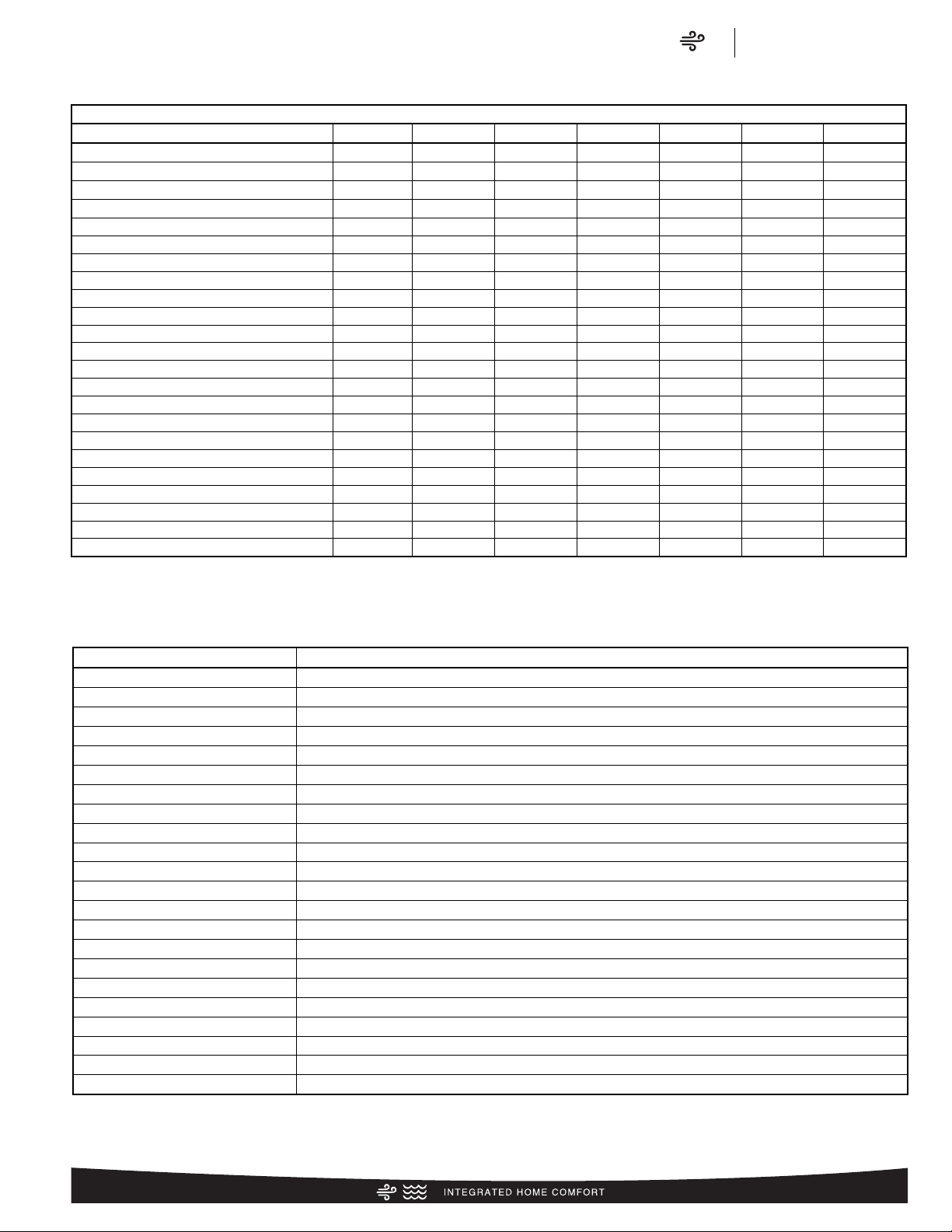
Weighted Sound Power Level (dBA)
RA13 Sound Power Level
Model
Sound Power
Level [dB(A)]
Full Octave Linear Sound Power Level dB - Center Frequency - Hz
Sound Power
Level [dB(A)]
with Sound
Blanket
125 250 500 1000 2000 4000 6300 8000
RA1318 79.1 57.3 63.1 69.8 69.5 65.6 60.5 56.3 53.3 NR
RA1324 75.5 55.4 60.3 64.7 66.4 62.6 58.0 54.3 52.4 NR
RA1330 78.1 51.4 67.4 67.5 68.2 65.5 59.8 55.6 53.6 NR
RA1336 77.5 55.1 66.1 66.9 68.2 64.6 60.7 57.4 55.6 NR
RA1342 72.7 48.9 56.1 62.9 62.2 61.1 55.2 51.9 50.2 NR
RA1348 75.8 51.4 59.6 65.2 65.9 64.3 58.5 55.2 53.7 75.2
RA1360 77.7 51.7 60.9 66.9 70.4 63.5 57.4 55.4 53.8 NR
NOTE: Tested in accordance with AHRI Standard 270-08 (not listed in AHRI)
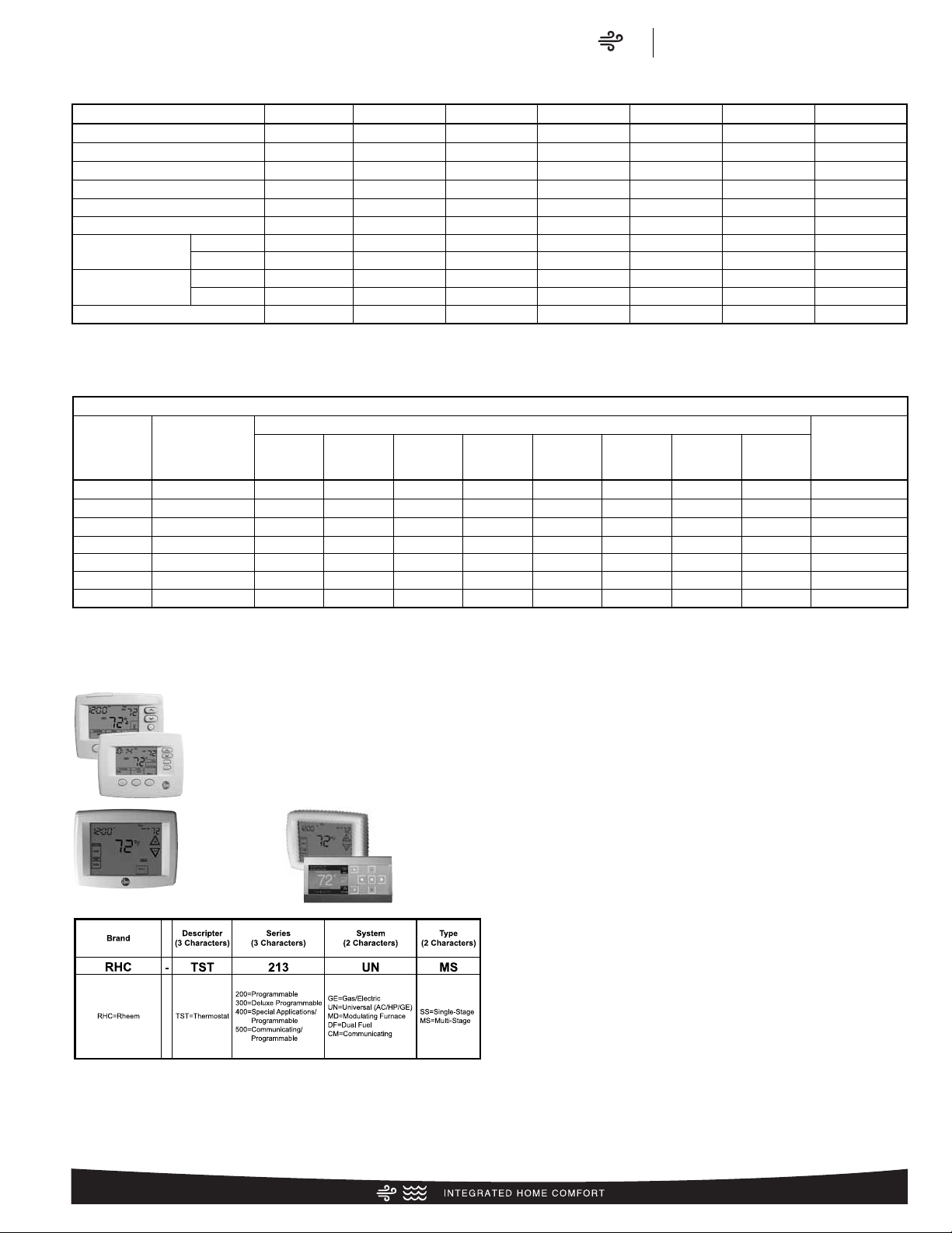
* Photos are representative. Actual models may vary.
For detailed thermostat match-up information,
see specification sheet form number T11-001.
300-Series *
Deluxe
Programmable
400-Series *
Special Applications/
Programmable
500-Series *
Communicating/
Programmable
200-Series *
Programmable
Thermostats
Page 10
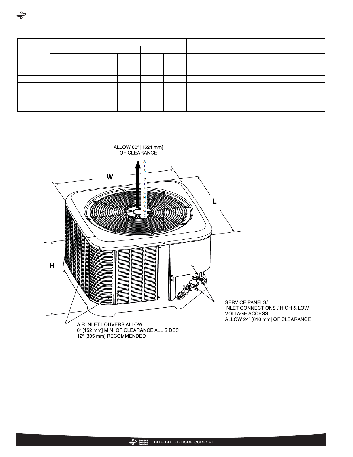
Unit Dimensions
MODEL
NO.
OPERATING SHIPPING
H (Height) L (Length) W (Width) H (Height) L (Length) W (Width)
INCHES mm INCHES mm INCHES mm INCHES mm INCHES mm INCHES mm
RA1318 27 685 29.75 755 29.75 755 28.75 730 32.38 822 32.38 822
RA1324 25 635 29.75 755 29.75 755 26.75 679 32.38 822 32.38 822
RA1330 25 635 29.75 755 29.75 755 26.75 679 32.38 822 32.38 822
RA1336 27 685 29.75 755 29.75 755 28.75 730 32.38 822 32.38 822
RA1342 31 787 29.75 755 29.75 755 32.75 831 32.38 822 32.38 822
RA1348 27 685 33.75 857 33.75 857 28.75 730 36.38 924 36.38 924
RA1360 31 787 35.75 908 35.75 908 32.75 831 38.38 974 38.38 974
[ ] Designates Metric Conversions
ST-A1226-02-00
Air
Unit Dimensions
RA13 Series
10
Page 11
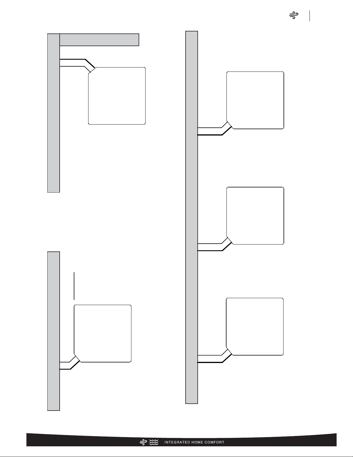
6⬙
(152.4)
24⬙
(609.6)
Service
12⬙
(304.8)
6⬙
(152.4)
24⬙
(609.6)
Service
24⬙
(609.6)
24⬙ recommended
9⬙ minimum
12⬙
(304.8)
12⬙
(304.8)
6⬙
(152.4)
24⬙
(609.6)
Service
24⬙
(609.6)
Service
24⬙
(609.6)
Service
18⬙
(457.2)
WALL
WALL
WALL
WALL
NOTE: NUMBERS IN () = mm
CLEARANCES
IMPORTANT: When installing multiple units in an alcove, roof well or partially enclosed area, ensure there is adequate ventillation to prevent re-circulation of discharge air.
ST-A1225-01-00
24⬙
(609.6)
24⬙ recommended
9⬙ minimum
Air
Clearances
RA13 Series
11
Page 12

Application Guidelines
1. Intended for outdoor installation with free air inlet and outlet. Outdoor fan external static pressure available is less than 0.01 -in. wc.
2. Minimum outdoor operation air temperature for cooling mode without low-ambient operation accessory is 55°F (12.8°C).
3. Maximum outdoor operating air temperature is 125°F (51.7°C).
4. For reliable operation, unit should be level in all horizontal planes.
5. Use only copper wire for electric connections at unit. Aluminum and clad aluminum are not acceptable for the type of connector
provided.
6. Do not apply capillary tube indoor coils to these units.
7. Factory – supplied filter drier must be installed.
Air
Wiring Diagram/Application Guidelines
RA13 Series
12
Control Wiring
FIGURE 2
CONTROL WIRING FOR GAS OR OIL FURNACE
IF MAXIMUM OUTLET TEMPERATURE RISE IS DESIRED, IT IS RECOMMENDED THAT
*
W1 (W/BK) AND W2 (W/BL) BE JUMPERED TOGETHER.
FOR TYPICAL GAS OR OIL HEAT
BR – BROWN WIRE
YL – YELLOW WIRE
X – WIRE CONNECTION
TYPICAL CONDENSING
UNIT
YL
X
BR
X
TYPICAL THERMOSTAT
SUBBASE
YGWR
TYPICAL GAS OR
OIL FURNACE
R
W
G
Y
C
FOR TYPICAL ELECTRIC HEAT
BR – BROWN WIRE
R – RED WIRE
YL – YELLOW WIRE
W/BK – WHITE WIRE WITH BLACK STRIPE
G/BK – GREEN WIRE WITH BLACK STRIPE
PU – PURPLE WIRE (NOT USED)
X – WIRE CONNECTION
TYPICAL CONDENSING
UNIT
YL
BR
*
X
X
TYPICAL THERMOSTAT
SUBBASE
YGWR
TYPICAL ELECTRIC HEAT
LOW VOLTAGE JUNCTION BOX
X
•
X
X
X
X
X
W/BL
R
W/BK
G/BK
YL
BR
PU
Page 13
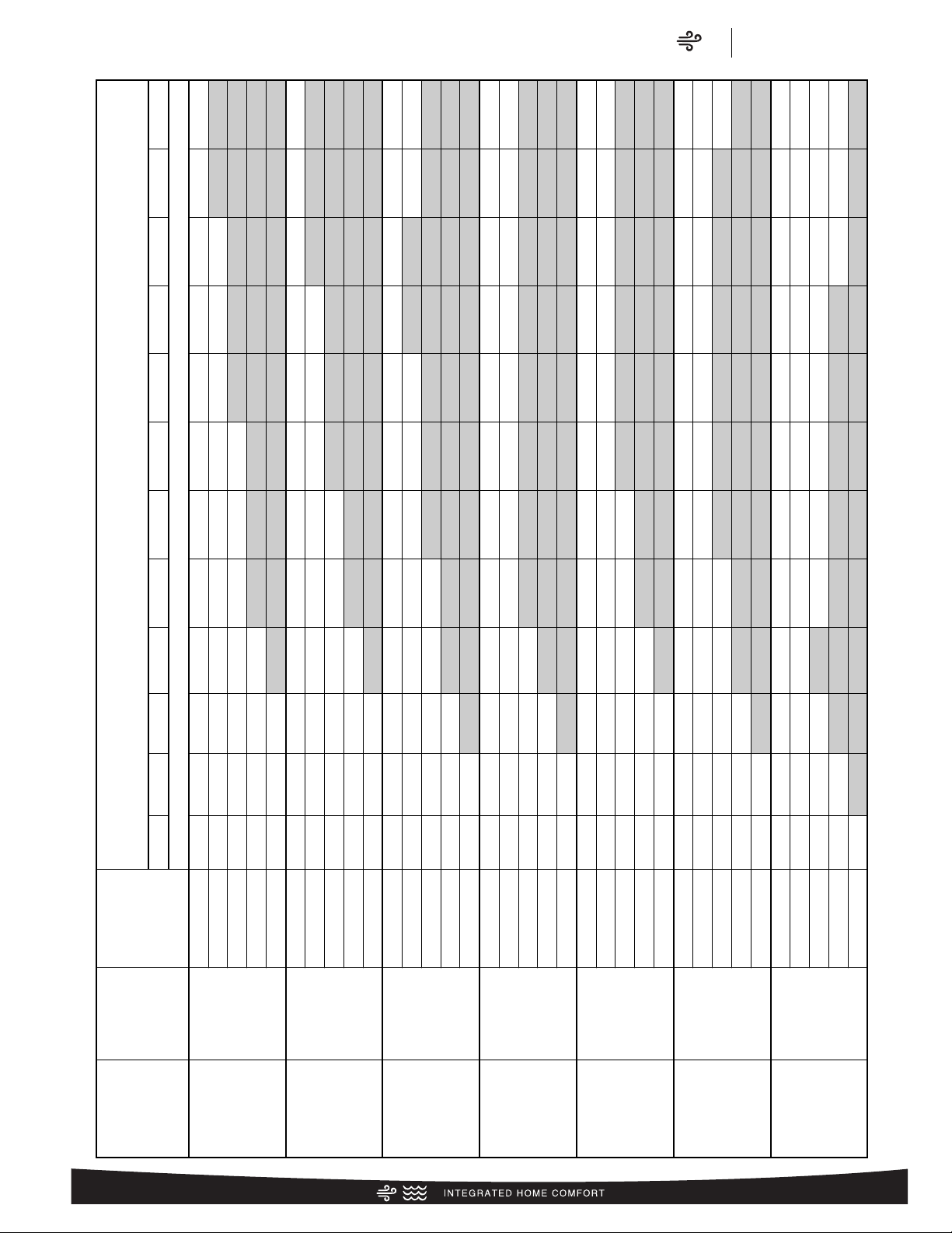
Air
Refrigerant Line Size Information
RA13 Series
13
R-410A System
Capacity Model
Liquid Line Size
Connection Size
(Inch I.D.) [mm]
Liquid Line Size
(Inch O.D.) [mm]
Liquid Line Size
Elevation (Above or Below) Indoor Coil
Tot al Equivalent Length - Feet [m]
25 [7.62] 50 [15.24] 75 [22.86] 100 [30.48] 125 [45.72] 150 [45.72] 175 [53.34] 200 [60.96] 225 [68.58] 250 [76.20] 275 [83.82] 300 [91.44]
Maximum Vertical Separation – Feet [m]
18 3/8" [9.53]
1/4 [6.35] 25 [7.62] 50 [15.24] 65 [19.81] 50 [15.24] 40 [12.19] 25 [7.62] 10 [3.05]
N/R N/R N/R N/R N/R
5/16 [7.94] 25 [7.62] 50 [15.24] 75 [22.86] 95 [28.96] 90 [27.43] 90 [27.43] 85 [25.91] 80 [24.38] 75 [22.86] 75 [22.86] 70 [21.34] 65 [19.81]
3/8 [9.53] 25 [7.62] 50 [15.24] 75 [22.86] 100 [30.48] 105 [32] 100 [30.48] 100 [30.48] 100 [30.48] 100 [30.48] 95 [28.96] 95 [28.96] 95 [28.96]
7/16 [11.12] 25 [7.62] 50 [15.24] 75 [22.86] 100 [30.48] 105 [32] 105 [32] 105 [32] 105 [32] 105 [32] 105 [32] 105 [32] 105 [32]
1/2 [12.71] 25 [7.62] 50 [15.24] 75 [22.86] 100 [30.48] 110 [33.53] 110 [33.53] 110 [33.53] 110 [33.53] 105 [32] 105 [32] 105 [32] 105 [32]
24 3/8" [9.53]
1/4 [6.35] 25 [7.62] 50 [15.24] 35 [10.67] 10 [3.05]
N/R N/R N/R N/R N/R N/R N/R N/R
5/16 [7.94] 25 [7.62] 50 [15.24] 75 [22.86] 85 [25.91] 75 [22.86] 70 [21.34] 65 [19.81] 55 [16.76] 50 [15.24] 45 [13.72] 40 [12.19] 30 [9.14]
3/8 [9.53] 25 [7.62] 50 [15.24] 75 [22.86] 100 [30.48] 100 [30.48] 95 [28.96] 95 [28.96] 90 [27.43] 90 [27.43] 85 [25.91] 85 [25.91] 80 [24.38]
7/16 [11.12] 25 [7.62] 50 [15.24] 75 [22.86] 100 [30.48] 105 [32] 105 [32] 100 [30.48] 100 [30.48] 100 [30.48] 100 [30.48] 100 [30.48] 95 [28.96]
1/2 [12.71] 25 [7.62] 50 [15.24] 75 [22.86] 100 [30.48] 105 [32] 105 [32] 105 [32] 105 [32] 105 [32] 105 [32] 105 [32] 105 [32]
30 3/8" [9.53]
1/4 [6.35] 25 [7.62] 25 [7.62]
N/R N/R N/R N/R N/R N/R N/R N/R N/R N/R
5/16 [7.94] 25 [7.62] 50 [15.24] 75 [22.86] 65 [19.81] 55 [16.76] 45 [13.72] 35 [10.67] 25 [7.62] 15 [4.57] 5 [1.52]
N/R N/R
3/8 [9.53] 25 [7.62] 50 [15.24] 75 [22.86] 90 [27.43] 90 [27.43] 85 [25.91] 80 [24.38] 80 [24.38] 75 [22.86] 70 [21.34] 65 [19.81] 65 [19.81]
7/16 [11.12] 25 [7.62] 50 [15.24] 75 [22.86] 100 [30.48] 95 [28.96] 95 [28.96] 95 [28.96] 95 [28.96] 90 [27.43] 90 [27.43] 90 [27.43] 85 [25.91]
1/2 [12.71] 25 [7.62] 50 [15.24] 75 [22.86] 100 [30.48] 100 [30.48] 100 [30.48] 100 [30.48] 100 [30.48] 100 [30.48] 100 [30.48] 95 [28.96] 95 [28.96]
36 3/8" [9.53]
1/4 [6.35] 25 [7.62]
N/R N/R N/R N/R N/R N/R N/R N/R N/R N/R N/R
5/16 [7.94] 25 [7.62] 50 [15.24] 65 [19.81] 50 [15.24] 35 [10.67] 25 [7.62] 10 [3.05] N/R
N/R N/R N/R N/R
3/8 [9.53] 25 [7.62] 50 [15.24] 75 [22.86] 85 [25.91] 80 [24.38] 75 [22.86] 70 [21.34] 65 [19.81] 60 [18.29] 60 [18.29] 55 [16.76] 50 [15.24]
7/16 [11.12] 25 [7.62] 50 [15.24] 75 [22.86] 95 [28.96] 95 [28.96] 90 [27.43] 90 [27.43] 85 [25.91] 85 [25.91] 85 [25.91] 80 [24.38] 80 [24.38]
1/2 [12.71] 25 [7.62] 50 [15.24] 75 [22.86] 100 [30.48] 100 [30.48] 95 [28.96] 95 [28.96] 95 [28.96] 95 [28.96] 95 [28.96] 90 [27.43] 90 [27.43]
42 3/8" [9.53]
1/4 [6.35] 25 [7.62]
N/R N/R N/R N/R N/R N/R N/R N/R N/R N/R N/R
5/16 [7.94] 25 [7.62] 50 [15.24] 50 [15.24] 30 [9.14] 15 [4.57]
N/R N/R N/R N/R N/R N/R N/R
3/8 [9.53] 25 [7.62] 50 [15.24] 75 [22.86] 80 [24.38] 70 [21.34] 65 [19.81] 60 [18.29] 55 [16.76] 50 [15.24] 40 [12.19] 35 [10.67] 30 [9.14]
7/16 [11.12] 25 [7.62] 50 [15.24] 75 [22.86] 95 [28.96] 90 [27.43] 90 [27.43] 85 [25.91] 80 [24.38] 80 [24.38] 75 [22.86] 75 [22.86] 70 [21.34]
1/2 [12.71] 25 [7.62] 50 [15.24] 75 [22.86] 100 [30.48] 95 [28.96] 95 [28.96] 95 [28.96] 95 [28.96] 90 [27.43] 90 [27.43] 90 [27.43] 90 [27.43]
48 3/8" [9.53]
1/4 [6.35] 5 [1.52]
N/R N/R N/R N/R N/R N/R N/R N/R N/R N/R N/R
5/16 [7.94] 25 [7.62] 50 [15.24] 30 [9.14] 5 [1.52]
N/R N/R N/R N/R N/R N/R N/R N/R
3/8 [9.53] 25 [7.62] 50 [15.24] 75 [22.86] 65 [19.81] 60 [18.29] 50 [15.24] 45 [13.72] 35 [10.67] 25 [7.62] 20 [6.1] 10 [3.05]
N/R
7/16 [11.12] 25 [7.62] 50 [15.24] 75 [22.86] 85 [25.91] 80 [24.38] 80 [24.38] 75 [22.86] 70 [21.34] 70 [21.34] 65 [19.81] 60 [18.29] 60 [18.29]
1/2 [12.71] 25 [7.62] 50 [15.24] 75 [22.86] 90 [27.43] 90 [27.43] 90 [27.43] 85 [25.91] 85 [25.91] 85 [25.91] 80 [24.38] 80 [24.38] 80 [24.38]
60 3/8" [9.53]
1/4 [6.35]
N/R N/R N/R N/R N/R N/R N/R N/R N/R N/R N/R N/R
5/16 [7.94] 20 [6.1]
N/R N/R N/R N/R N/R N/R N/R N/R N/R N/R N/R
3/8 [9.53] 25 [7.62] 30 [9.14] 20 [6.1] 5 [1.52] N/R
N/R N/R N/R N/R N/R N/R N/R
7/16 [11.12] 25 [7.62] 45 [13.72] 40 [12.19] 35 [10.67] 30 [9.14] 25 [7.62] 20 [6.1] 15 [4.57] 10 [3.05] N/R N/R N/R
1/2 [12.71] 25 [7.62] 50 [15.24] 45 [13.72] 45 [13.72] 40 [12.19] 40 [12.19] 35 [10.67] 35 [10.67] 30 [9.14] 30 [9.14] 25 [7.62] 25 [7.62]
Refrigerant Line Size Information
NOTES: [ ] Designates Metric Conversions
N/R = Application not recommended.
Grey =This application is acceptable, but the long line guidelines must be followed. Reference Long Line Set section in the I&O
Page 14
Air
Refrigerant Line Size Information
RA13 Series
14
R-410A System
Capacity Model
Vapor Line
Connection Size
(Inch I.D.) [mm]
Vapor Line Size
(Inch O.D.) [mm]
Vapor Line Selection Chart
Capacity Multiplier Table
Tot al Equivalent Length - Feet [m]
25 [7.62] 50 [15.24] 75 [22.86] 100 [30.48] 125 [45.72] 150 [45.72] 175 [53.34] 200 [60.96] 225 [68.58] 250 [76.20] 275 [83.82] 300 [91.44]
18 3/4" [19.06]
5/8 [15.88]
1.00 0.99 0.99 0.98 0.98 0.98 0.97 0.97 0.96 0.96 0.96 0.95
3/4 [19.05]
1.00 1.00 1.00 1.00 1.00 0.99 0.99 0.99 0.99 0.99 0.99 0.99
7/8 [22.23]
N/R N/R N/R N/R N/R N/R N/R N/R N/R N/R N/R N/R
1 [25.4]
N/R N/R N/R N/R N/R N/R N/R N/R N/R N/R N/R N/R
1-1/8 [28.58]
N/R N/R N/R N/R N/R N/R N/R N/R N/R N/R N/R N/R
24 3/4" [19.06]
5/8 [15.88]
1.00 0.99 0.99 0.98 0.98 0.98 0.97 0.97 0.96 0.96 0.96 0.95
3/4 [19.05]
1.00 1.00 1.00 1.00 1.00 0.99 0.99 0.99 0.99 0.99 0.99 0.99
7/8 [22.23]
1.00 1.00 1.00 1.00 1.00 1.00 1.00 1.00 1.00 1.00 1.00 1.00
1 [25.4]
N/R N/R N/R N/R N/R N/R N/R N/R N/R N/R N/R N/R
1-1/8 [28.58]
N/R N/R N/R N/R N/R N/R N/R N/R N/R N/R N/R N/R
30 3/4" [19.06]
5/8 [15.88]
1.00 0.99 0.99 0.98 0.98 0.98 0.97 0.97 0.96 0.96 0.96 0.95
3/4 [19.05]
1.00 1.00 1.00 1.00 1.00 0.99 0.99 0.99 0.99 0.99 0.99 0.99
7/8 [22.23]
1.00 1.00 1.00 1.00 1.00 1.00 1.00 1.00 1.00 1.00 1.00 1.00
1 [25.4]
1.00 1.00 1.00 1.00 1.00 1.00 1.00 1.00 1.00 1.01 1.01 1.01
1-1/8 [28.58]
N/R N/R N/R N/R N/R N/R N/R N/R N/R N/R N/R N/R
36 3/4" [19.06]
5/8 [15.88]
1.00 0.99 0.99 0.98 0.98 0.98 0.97 0.97 0.96 0.96 0.96 0.95
3/4 [19.05]
1.00 1.00 1.00 1.00 1.00 0.99 0.99 0.99 0.99 0.99 0.99 0.99
7/8 [22.23]
1.00 1.00 1.00 1.00 1.00 1.00 1.00 1.00 1.00 1.00 1.00 1.00
1 [25.4]
1.00 1.00 1.00 1.00 1.00 1.00 1.00 1.00 1.00 1.01 1.01 1.01
1-1/8 [28.58]
1.00 1.00 1.00 1.00 1.00 1.00 1.01 1.01 1.01 1.01 1.01 1.01
42 7/8" [22.23]
5/8 [15.88]
1.00 0.99 0.99 0.98 0.98 0.98 0.97 0.97 0.96 0.96 0.96 0.95
3/4 [19.05]
1.00 1.00 1.00 1.00 1.00 0.99 0.99 0.99 0.99 0.99 0.99 0.99
7/8 [22.23]
1.00 1.00 1.00 1.00 1.00 1.00 1.00 1.00 1.00 1.00 1.00 1.00
1 [25.4]
1.00 1.00 1.00 1.00 1.00 1.00 1.00 1.00 1.00 1.01 1.01 1.01
1-1/8 [28.58]
1.00 1.00 1.00 1.00 1.00 1.00 1.01 1.01 1.01 1.01 1.01 1.01
48 7/8" [22.23]
5/8 [15.88]
1.00 0.99 0.99 0.98 0.98 0.98 0.97 0.97 0.96 0.96 0.96
N/R
3/4 [19.05]
1.00 1.00 1.00 1.00 1.00 0.99 0.99 0.99 0.99 0.99 0.99
N/R
7/8 [22.23]
1.00 1.00 1.00 1.00 1.00 1.00 1.00 1.00 1.00 1.00 1.00
N/R
1 [25.4]
1.00 1.00 1.00 1.00 1.00 1.00 1.00 1.00 1.00 1.01 1.01
N/R
1-1/8 [28.58]
N/R N/R N/R N/R N/R N/R N/R N/R N/R N/R N/R N/R
60 7/8" [22.23]
5/8 [15.88]
1.00 0.99 0.99 0.98
N/R N/R N/R N/R N/R N/R N/R N/R
3/4 [19.05]
1.00 1.00 1.00 1.00
N/R N/R N/R N/R N/R N/R N/R N/R
7/8 [22.23]
1.00 1.00 1.00 1.00
N/R N/R N/R N/R N/R N/R N/R N/R
1 [25.4]
1.00 1.00 1.00 1.00
N/R N/R N/R N/R N/R N/R N/R N/R
1-1/8 [28.58]
1.00 1.00 1.00 1.00
N/R N/R N/R N/R N/R N/R N/R N/R
Refrigerant Line Size Information (con’t.)
NOTES: [ ] Designates Metric Conversions
N/R = Application not recommended.
All calculations assume a 3/8" liquid line
Page 15

Air
Performance Data
RA13 Series
Performance Data @ AHRI Standard Conditions – Cooling
High Sales Volume Tested Combination (HSVTC)
Outdoor
Unit
Indoor Coil
Total Capacity
BTU/H [kW]
Net Sensible
BTU/H [kW]
Net Latent
BTU/H [kW]
SEER EER
Indoor CFM
[L/s]
AHRI#
RA1318AJ1 RCF2417STAM 17600 [5.2] 13100 [3.8] 4500 [1.3] 13 11 600 [283.2] 7507439
RA1324AJ1 RCF2417STAM 23600 [6.9] 17600 [5.2] 6000 [1.8] 13 11 800 [377.6] 7507649
RA1330AJ1 RCF3617STAM 28400 [8.3] 21600 [6.3] 6800 [2.0] 13 11 1000 [471.9] 7507846
RA1336AC1 RCF3617STAM 34600 [10.1] 24500 [7.2] 10100 [3.0] 13 11 1025 [483.7] 7508191
RA1336AJ1 RCF3617STAM 34600 [10.1] 24500 [7.2] 10100 [3.0] 13 11 1025 [483.7] 7508557
RA1342AC1 RCF4821STAM 40500 [11.9] 30300 [8.9] 10200 [3.0] 13 11 1400 [660.7] 7511558
RA1342AJ1 RCF4821STAM 40500 [11.9] 30300 [8.9] 10200 [3.0] 13 11 1400 [660.7] 7511792
RA1348AC1 RCF4821STAM 47500 [13.9] 34100 [10.0] 13400 [3.9] 13 11 1500 [707.9] 7508923
RA1348AJ1 RCF4821STAM 47500 [13.9] 34100 [10.0] 13400 [3.9] 13 11 1500 [707.9] 7509148
RA1360AC1 RCF6024STAM 56000 [16.4] 39600 [11.6] 16400 [4.8] 13 11 1600 [755.1] 7509314
RA1360AJ1 RCF6024STAM 56000 [16.4] 39600 [11.6] 16400 [4.8] 13 11 1600 [755.1] 7509436
Coil Only Ratings
Outdoor
Unit
Indoor Coil
Total Capacity
BTU/H [kW]
Net Sensible
BTU/H [kW]
Net Latent
BTU/H [kW]
SEER EER
Indoor CFM
[L/s]
AHRI#
RA1318AJ1
RCF2414STAM+RXMD-C04 17600 [5.2] 12600 [3.7] 5000 [1.5] 13 11 600 [283.2] 7507408
RCF2417HTAM+RXMD-C04 17500 [5.1] 12300 [3.6] 5200 [1.5] 13 11 600 [283.2] 7507423
RCF2417MTAM+RXMD-C04 17500 [5.1] 12300 [3.6] 5200 [1.5] 13 11 600 [283.2] 7507438
RCF2421MTAM+RXMD-C04 17500 [5.1] 12300 [3.6] 5200 [1.5] 13 11 600 [283.2] 7507491
RA1324AJ1
RCF2414STAM+RXMD-C04 23800 [7.0] 17100 [5.0] 6700 [2.0] 13 11 800 [377.6] 7507612
RCF2417HTAM+RXMD-C04 23400 [6.9] 16500 [4.8] 6900 [2.0] 13 11 800 [377.6] 7507630
RCF2417MTAM+RXMD-C04 23400 [6.9] 16500 [4.8] 6900 [2.0] 13 11 800 [377.6] 7507648
RCF2421MTAM+RXMD-C04 23400 [6.9] 16500 [4.8] 6900 [2.0] 13 11 800 [377.6] 7507716
RA1330AJ1
RCF3621MTAM+RXMD-C04 29800 [8.7] 21900 [6.4] 7900 [2.3] 13.5 11.5 1000 [471.9] 7507895
RCF3621STAM+RXMD-C04 28400 [8.3] 20500 [6.0] 7900 [2.3] 13 11 1000 [471.9] 7507926
RCF3624HTAM+RXMD-C04 30400 [8.9] 22200 [6.5] 8200 [2.4] 13.5 11.5 1000 [471.9] 7507950
RCF3624MTAM+RXMD-C04 29800 [8.7] 21900 [6.4] 7900 [2.3] 13.5 11.5 1000 [471.9] 7507973
RA1336AC1
RCF3621MTAM+RXMD-C04 36600 [10.7] 24900 [7.3] 11700 [3.4] 13.5 11.5 1025 [483.7] 7508240
RCF3621STAM+RXMD-C04 34400 [10.1] 23100 [6.8] 11300 [3.3] 13 11 1025 [483.7] 7508271
RCF3624HTAM+RXMD-C04 37400 [11.0] 25600 [7.5] 11800 [3.5] 13.5 11.5 1025 [483.7] 7508298
RCF3624MTAM+RXMD-C04 36600 [10.7] 24900 [7.3] 11700 [3.4] 13.5 11.5 1025 [483.7] 7508325
RA1336AJ1
RCF3621MTAM+RXMD-C04 36600 [10.7] 24900 [7.3] 11700 [3.4] 13.5 11.5 1025 [483.7] 7508606
RCF3621STAM+RXMD-C04 34400 [10.1] 23100 [6.8] 11300 [3.3] 13 11 1025 [483.7] 7508637
RCF3624HTAM+RXMD-C04 37400 [11.0] 25600 [7.5] 11800 [3.5] 13.5 11.5 1025 [483.7] 7508664
RCF3624MTAM+RXMD-C04 36600 [10.7] 24900 [7.3] 11700 [3.4] 13.5 11.5 1025 [483.7] 7508691
RA1342AC1
RCF4824HTAM+RXMD-C04 41500 [12.2] 29400 [8.6] 12100 [3.5] 13 11.5 1400 [660.7] 7511616
RCF4824STAM+RXMD-C04 40000 [11.7] 28000 [8.2] 12000 [3.5] 13 11 1375 [648.9] 7511643
RA1342AJ1
RCF4824HTAM+RXMD-C04 41500 [12.2] 29400 [8.6] 12100 [3.5] 13 11.5 1400 [660.7] 7511850
RCF4824STAM+RXMD-C04 40000 [11.7] 28000 [8.2] 12000 [3.5] 13 11 1375 [648.9] 7511877
RA1348AC1
RCF4824HTAM+RXMD-C04 49500 [14.5] 34200 [10.0] 15300 [4.5] 13 11.5 1500 [707.9] 7508968
RCF4824STAM+RXMD-C04 47500 [13.9] 34100 [10.0] 13400 [3.9] 13 11 1500 [707.9] 7509019
RA1348AJ1
RCF4824HTAM+RXMD-C04 49500 [14.5] 34200 [10.0] 15300 [4.5] 13 11.5 1500 [707.9] 7509188
RCF4824STAM+RXMD-C04 47500 [13.9] 34100 [10.0] 13400 [3.9] 13 11 1500 [707.9] 7509210
RA1360AC1
RCF6024HTAM+RXMD-C04 56000 [16.4] 39600 [11.6] 16400 [4.8] 13 11 1600 [755.1] 7509313
RCF6024HTAM+RXMD-C04 56000 [16.4] 39600 [11.6] 16400 [4.8] 13 11 1600 [755.1] 7509435
[ ] Designates Metric Conversions
15
Page 16

Air
Performance Data
RA13 Series
16
Performance Data @ AHRI Standard Conditions – Cooling (con’t.)
R801T Furnace Ratings
Outdoor
Unit
Furnace Indoor Coil
Total Capacity
BTU/H [kW]
Net Sensible
BTU/H [kW]
Net Latent
BTU/H [kW]
SEER EER
Indoor CFM
[L/s]
AHRI#
RA1318AJ1 R801TA050314MSA
RCF2414STAM 18100 [5.3] 13100 [3.8] 5000 [1.5] 14.5 12 625 [295.0] 7507407
RCF2417HTAM 18000 [5.3] 12800 [3.8] 5200 [1.5] 14.5 12 625 [295.0] 7507409
RCF2417MTAM 18000 [5.3] 12800 [3.8] 5200 [1.5] 14.5 12 625 [295.0] 7507424
RCF2417STAM 18000 [5.3] 13500 [4.0] 4500 [1.3] 14.5 12 625 [295.0] 7507440
RA1318AJ1 R801TA075317ZSA
RCF2417HTAM 18300 [5.4] 13200 [3.9] 5100 [1.5] 14.5 12 650 [306.8] 7507410
RCF2417MTAM 18300 [5.4] 13200 [3.9] 5100 [1.5] 14.5 12 650 [306.8] 7507425
RCF2417STAM 18300 [5.4] 13900 [4.1] 4400 [1.3] 14.5 12 650 [306.8] 7507441
RCF2421MTAM 18300 [5.4] 13200 [3.9] 5100 [1.5] 14.5 12 650 [306.8] 7507473
RA1324AJ1 R801TA050314MSA
RCF2414STAM 24400 [7.2] 17700 [5.2] 6700 [2.0] 14.5 12 800 [377.6] 7507611
RCF2417HTAM 24400 [7.2] 17700 [5.2] 6700 [2.0] 14.5 12 875 [413.0] 7507613
RCF2417MTAM 24200 [7.1] 17500 [5.1] 6700 [2.0] 14.5 12 850 [401.2] 7507631
RCF2417STAM 24200 [7.1] 18300 [5.4] 5900 [1.7] 14 11.5 825 [389.4] 7507650
RA1324AJ1 R801TA075317ZSA
RCF2417HTAM 24400 [7.2] 17700 [5.2] 6700 [2.0] 14 11.5 875 [413.0] 7507614
RCF2417MTAM 24400 [7.2] 17700 [5.2] 6700 [2.0] 14 11.5 875 [413.0] 7507632
RCF2417STAM 24200 [7.1] 18400 [5.4] 5800 [1.7] 14 11.5 850 [401.2] 7507651
RCF2421MTAM 24400 [7.2] 17700 [5.2] 6700 [2.0] 14 11.5 875 [413.0] 7507692
RA1330AJ1 R801TA050314MSA RCF3617STAM 28800 [8.4] 22000 [6.4] 6800 [2.0] 14 11.5 1000 [471.9] 7507847
RA1330AJ1 R801TA075317ZSA
RCF3617STAM 28400 [8.3] 21200 [6.2] 7200 [2.1] 14 11.5 875 [413.0] 7507848
RCF3621MTAM 30800 [9.0] 23200 [6.8] 7600 [2.2] 14.5 12 1075 [507.3] 7507865
RCF3621STAM 28400 [8.3] 21200 [6.2] 7200 [2.1] 14 11.5 875 [413.0] 7507896
RA1330AJ1 R801TA075417MSA
RCF3617STAM 29000 [8.5] 22200 [6.5] 6800 [2.0] 14 11.5 1000 [471.9] 7507849
RCF3621MTAM 30800 [9.0] 23100 [6.8] 7700 [2.3] 14.5 12 1050 [495.5] 7507866
RCF3621STAM 29200 [8.6] 22500 [6.6] 6700 [2.0] 14 11.5 1025 [483.7] 7507897
RA1330AJ1 R801TA075521ZSA
RCF3621MTAM 30600 [9.0] 22700 [6.7] 7900 [2.3] 15 12.5 1000 [471.9] 7507867
RCF3621STAM 29000 [8.5] 22100 [6.5] 6900 [2.0] 14 11.5 975 [460.1] 7507898
RCF3624HTAM 31200 [9.1] 23000 [6.7] 8200 [2.4] 15.5 13 1025 [483.7] 7507927
RCF3624MTAM 30600 [9.0] 22700 [6.7] 7900 [2.3] 15 12.5 1000 [471.9] 7507951
RA1330AJ1 R801TA100521MSA
RCF3621MTAM 30800 [9.0] 23100 [6.8] 7700 [2.3] 15.1 12.5 1050 [495.5] 7507868
RCF3621STAM 29000 [8.5] 22200 [6.5] 6800 [2.0] 14 11.5 1000 [471.9] 7507899
RCF3624HTAM 31800 [9.3] 24000 [7.0] 7800 [2.3] 15.5 13 1100 [519.1] 7507928
RCF3624MTAM 30800 [9.0] 23100 [6.8] 7700 [2.3] 15.1 12.5 1050 [495.5] 7507952
RA1330AJ1 R801TA100521ZSA
RCF3621MTAM 30600 [9.0] 22600 [6.6] 8000 [2.3] 15.1 12.5 975 [460.1] 7507869
RCF3621STAM 29000 [8.5] 22100 [6.5] 6900 [2.0] 14 11.5 975 [460.1] 7507900
RCF3624HTAM 31200 [9.1] 23000 [6.7] 8200 [2.4] 15.5 13 1025 [483.7] 7507929
RCF3624MTAM 30600 [9.0] 22600 [6.6] 8000 [2.3] 15.1 12.5 975 [460.1] 7507953
RA1330AJ1 R801TA125524ZSA
RCF3624HTAM 31200 [9.1] 22900 [6.7] 8300 [2.4] 15.5 13 975 [460.1] 7507930
RCF3624MTAM 30200 [8.9] 22000 [6.4] 8200 [2.4] 15 12.5 925 [436.6] 7507954
RA1336AC1 R801TA050314MSA RCF3617STAM 35000 [10.3] 24700 [7.2] 10300 [3.0] 13.5 11.5 1000 [471.9] 7508192
RA1336AC1 R801TA075317ZSA
RCF3617STAM 35000 [10.3] 25000 [7.3] 10000 [2.9] 13.5 11.5 1050 [495.5] 7508193
RCF3621MTAM 38000 [11.1] 27300 [8.0] 10700 [3.1] 14 11.5 1250 [589.9] 7508210
RCF3621STAM 35000 [10.3] 25000 [7.3] 10000 [2.9] 13.5 11.5 1050 [495.5] 7508241
RA1336AC1 R801TA075417MSA
RCF3617STAM 36000 [10.6] 26800 [7.9] 9200 [2.7] 13.5 11.5 1225 [578.1] 7508194
RCF3621MTAM 38000 [11.1] 27100 [7.9] 10900 [3.2] 14.5 12 1200 [566.3] 7508211
RCF3621STAM 36000 [10.6] 26900 [7.9] 9100 [2.7] 13.5 11.5 1250 [589.9] 7508242
RA1336AC1 R801TA075521ZSA
RCF3621MTAM 37200 [10.9] 25300 [7.4] 11900 [3.5] 14.5 12 1000 [471.9] 7508212
RCF3621STAM 35800 [10.5] 26300 [7.7] 9500 [2.8] 13.5 11.5 1175 [554.5] 7508243
RCF3624HTAM 38000 [11.1] 26200 [7.7] 11800 [3.5] 15.1 12.5 1025 [483.7] 7508272
RCF3624MTAM 37200 [10.9] 25300 [7.4] 11900 [3.5] 14.5 12 1000 [471.9] 7508299
[ ] Designates Metric Conversions
Page 17

Air
Performance Data
RA13 Series
17
Performance Data @ AHRI Standard Conditions – Cooling (con’t.)
R801T Furnace Ratings
Outdoor
Unit
Furnace Indoor Coil
Total Capacity
BTU/H [kW]
Net Sensible
BTU/H [kW]
Net Latent
BTU/H [kW]
SEER EER
Indoor CFM
[L/s]
AHRI#
RA1336AC1 R801TA100521MSA
RCF3621MTAM 37200 [10.9] 25500 [7.5] 11700 [3.4] 14.5 12 1050 [495.5] 7508213
RCF3621STAM 35200 [10.3] 24900 [7.3] 10300 [3.0] 14 11.5 1000 [471.9] 7508244
RCF3624HTAM 38500 [11.3] 27000 [7.9] 11500 [3.4] 15.1 12.5 1100 [519.1] 7508273
RCF3624MTAM 37200 [10.9] 25500 [7.5] 11700 [3.4] 14.5 12 1050 [495.5] 7508300
RA1336AC1 R801TA100521ZSA
RCF3621MTAM 38000 [11.1] 27200 [8.0] 10800 [3.2] 14.5 12 1225 [578.1] 7508214
RCF3621STAM 35800 [10.5] 26300 [7.7] 9500 [2.8] 13.5 11.5 1175 [554.5] 7508245
RCF3624HTAM 38000 [11.1] 26200 [7.7] 11800 [3.5] 15.1 12.5 1025 [483.7] 7508274
RCF3624MTAM 38000 [11.1] 27200 [8.0] 10800 [3.2] 14.5 12 1225 [578.1] 7508301
RA1336AC1 R801TA125524MSA
RCF3624HTAM 39000 [11.4] 28000 [8.2] 11000 [3.2] 15.1 12.5 1200 [566.3] 7508275
RCF3624MTAM 38000 [11.1] 26900 [7.9] 11100 [3.3] 14.5 12 1175 [554.5] 7508302
RA1336AC1 R801TA125524ZSA
RCF3624HTAM 39000 [11.4] 27800 [8.1] 11200 [3.3] 15.1 12.5 1150 [542.7] 7508276
RCF3624MTAM 37600 [11.0] 26200 [7.7] 11400 [3.3] 14.5 12 1100 [519.1] 7508303
RA1336AJ1 R801TA050314MSA RCF3617STAM 35000 [10.3] 24700 [7.2] 10300 [3.0] 13.5 11.5 1000 [471.9] 7508558
RA1336AJ1 R801TA075317ZSA
RCF3617STAM 35000 [10.3] 25000 [7.3] 10000 [2.9] 13.5 11.5 1050 [495.5] 7508559
RCF3621MTAM 38000 [11.1] 27300 [8.0] 10700 [3.1] 14 11.5 1250 [589.9] 7508576
RCF3621STAM 35000 [10.3] 25000 [7.3] 10000 [2.9] 13.5 11.5 1050 [495.5] 7508607
RA1336AJ1 R801TA075417MSA
RCF3617STAM 36000 [10.6] 26800 [7.9] 9200 [2.7] 13.5 11.5 1225 [578.1] 7508560
RCF3621MTAM 38000 [11.1] 27100 [7.9] 10900 [3.2] 14.5 12 1200 [566.3] 7508577
RCF3621STAM 36000 [10.6] 26900 [7.9] 9100 [2.7] 13.5 11.5 1250 [589.9] 7508608
RA1336AJ1 R801TA075521ZSA
RCF3621MTAM 37200 [10.9] 25300 [7.4] 11900 [3.5] 14.5 12 1000 [471.9] 7508578
RCF3621STAM 35800 [10.5] 26300 [7.7] 9500 [2.8] 13.5 11.5 1175 [554.5] 7508609
RCF3624HTAM 38000 [11.1] 26200 [7.7] 11800 [3.5] 15.1 12.5 1025 [483.7] 7508638
RCF3624MTAM 37200 [10.9] 25300 [7.4] 11900 [3.5] 14.5 12 1000 [471.9] 7508665
RA1336AJ1 R801TA100521MSA
RCF3621MTAM 37200 [10.9] 25500 [7.5] 11700 [3.4] 14.5 12 1050 [495.5] 7508579
RCF3621STAM 35200 [10.3] 24900 [7.3] 10300 [3.0] 14 11.5 1000 [471.9] 7508610
RCF3624HTAM 38500 [11.3] 27000 [7.9] 11500 [3.4] 15.1 12.5 1100 [519.1] 7508639
RCF3624MTAM 37200 [10.9] 25500 [7.5] 11700 [3.4] 14.5 12 1050 [495.5] 7508666
RA1336AJ1 R801TA100521ZSA
RCF3621MTAM 38000 [11.1] 27200 [8.0] 10800 [3.2] 14.5 12 1225 [578.1] 7508580
RCF3621STAM 35800 [10.5] 26300 [7.7] 9500 [2.8] 13.5 11.5 1175 [554.5] 7508611
RCF3624HTAM 38000 [11.1] 26200 [7.7] 11800 [3.5] 15.1 12.5 1025 [483.7] 7508640
RCF3624MTAM 38000 [11.1] 27200 [8.0] 10800 [3.2] 14.5 12 1225 [578.1] 7508667
RA1336AJ1 R801TA125524MSA
RCF3624HTAM 39000 [11.4] 28000 [8.2] 11000 [3.2] 15.1 12.5 1200 [566.3] 7508641
RCF3624MTAM 38000 [11.1] 26900 [7.9] 11100 [3.3] 14.5 12 1175 [554.5] 7508668
RA1336AJ1 R801TA125524ZSA
RCF3624HTAM 39000 [11.4] 27800 [8.1] 11200 [3.3] 15.1 12.5 1150 [542.7] 7508642
RCF3624MTAM 37600 [11.0] 26200 [7.7] 11400 [3.3] 14.5 12 1100 [519.1] 7508669
RA1342AC1 R801TA075317ZSA RCF4821STAM 40000 [11.7] 29000 [8.5] 11000 [3.2] 13.5 11.5 1250 [589.9] 7511559
RA1342AC1 R801TA075417MSA RCF4821STAM 40000 [11.7] 29100 [8.5] 10900 [3.2] 13.5 11.5 1275 [601.7] 7511560
RA1342AC1 R801TA075521ZSA
RCF4821STAM 40000 [11.7] 28800 [8.4] 11200 [3.3] 13.5 11.5 1225 [578.1] 7511561
RCF4824HTAM 41500 [12.2] 28600 [8.4] 12900 [3.8] 14 11.5 1250 [589.9] 7511589
RCF4824STAM 40000 [11.7] 28800 [8.4] 11200 [3.3] 13.5 11.5 1225 [578.1] 7511617
RA1342AC1 R801TA100521MSA
RCF4821STAM 40500 [11.9] 29900 [8.8] 10600 [3.1] 14 11.5 1325 [625.3] 7511562
RCF4824HTAM 42000 [12.3] 29600 [8.7] 12400 [3.6] 14.5 12 1350 [637.1] 7511590
RCF4824STAM 40500 [11.9] 29900 [8.8] 10600 [3.1] 14 11.5 1325 [625.3] 7511618
RA1342AC1 R801TA100521ZSA
RCF4821STAM 40500 [11.9] 30300 [8.9] 10200 [3.0] 13.5 11.5 1425 [672.5] 7511563
RCF4824HTAM 42500 [12.5] 30700 [9.0] 11800 [3.5] 14 11.5 1450 [684.3] 7511591
RCF4824STAM 40500 [11.9] 30300 [8.9] 10200 [3.0] 13.5 11.5 1425 [672.5] 7511619
RA1342AC1 R801TA125524MSA
RCF4824HTAM 42500 [12.5] 30400 [8.9] 12100 [3.5] 14.5 12 1400 [660.7] 7511592
RCF4824STAM 40500 [11.9] 30000 [8.8] 10500 [3.1] 14 11.5 1350 [637.1] 7511620
[ ] Designates Metric Conversions
Page 18

18
Air
Performance Data
RA13 Series
18
Performance Data @ AHRI Standard Conditions – Cooling (con’t.)
R801T Furnace Ratings
Outdoor
Unit
Furnace Indoor Coil
Total Capacity
BTU/H [kW]
Net Sensible
BTU/H [kW]
Net Latent
BTU/H [kW]
SEER EER
Indoor CFM
[L/s]
AHRI#
RA1342AC1 R801TA125524ZSA
RCF4824HTAM 41500 [12.2] 28100 [8.2] 13400 [3.9] 14.5 12 1150 [542.7] 7511593
RCF4824STAM 39500 [11.6] 27700 [8.1] 11800 [3.5] 14 11.5 1100 [519.1] 7511621
RA1342AJ1 R801TA075317ZSA RCF4821STAM 40000 [11.7] 29000 [8.5] 11000 [3.2] 13.5 11.5 1250 [589.9] 7511793
RA1342AJ1 R801TA075417MSA RCF4821STAM 40000 [11.7] 29100 [8.5] 10900 [3.2] 13.5 11.5 1275 [601.7] 7511794
RA1342AJ1 R801TA075521ZSA
RCF4821STAM 40000 [11.7] 28800 [8.4] 11200 [3.3] 13.5 11.5 1225 [578.1] 7511795
RCF4824HTAM 41500 [12.2] 28600 [8.4] 12900 [3.8] 14 11.5 1250 [589.9] 7511823
RCF4824STAM 40000 [11.7] 28800 [8.4] 11200 [3.3] 13.5 11.5 1225 [578.1] 7511851
RA1342AJ1 R801TA100521MSA
RCF4821STAM 40500 [11.9] 29900 [8.8] 10600 [3.1] 14 11.5 1325 [625.3] 7511796
RCF4824HTAM 42000 [12.3] 29600 [8.7] 12400 [3.6] 14.5 12 1350 [637.1] 7511824
RCF4824STAM 40500 [11.9] 29900 [8.8] 10600 [3.1] 14 11.5 1325 [625.3] 7511852
RA1342AJ1 R801TA100521ZSA
RCF4821STAM 40500 [11.9] 30300 [8.9] 10200 [3.0] 13.5 11.5 1425 [672.5] 7511797
RCF4824HTAM 42500 [12.5] 30700 [9.0] 11800 [3.5] 14 11.5 1450 [684.3] 7511825
RCF4824STAM 40500 [11.9] 30300 [8.9] 10200 [3.0] 13.5 11.5 1425 [672.5] 7511853
RA1342AJ1 R801TA125524MSA
RCF4824HTAM 42500 [12.5] 30400 [8.9] 12100 [3.5] 14.5 12 1400 [660.7] 7511826
RCF4824STAM 40500 [11.9] 30000 [8.8] 10500 [3.1] 14 11.5 1350 [637.1] 7511854
RA1342AJ1 R801TA125524ZSA
RCF4824HTAM 41500 [12.2] 28100 [8.2] 13400 [3.9] 14.5 12 1150 [542.7] 7511827
RCF4824STAM 39500 [11.6] 27700 [8.1] 11800 [3.5] 14 11.5 1100 [519.1] 7511855
RA1348AC1 R801TA075417MSA RCF4821STAM 47000 [13.8] 32800 [9.6] 14200 [4.2] 13 11.5 1375 [648.9] 7508924
RA1348AC1 R801TA075521ZSA
RCF4821STAM 47000 [13.8] 33000 [9.7] 14000 [4.1] 13 11.5 1400 [660.7] 7508925
RCF4824HTAM 50000 [14.7] 34300 [10.1] 15700 [4.6] 13.5 11.5 1450 [684.3] 7508939
RCF4824STAM 47000 [13.8] 33000 [9.7] 14000 [4.1] 13 11.5 1400 [660.7] 7508970
RA1348AC1 R801TA100521MSA
RCF4821STAM 47000 [13.8] 32800 [9.6] 14200 [4.2] 13.5 11.5 1375 [648.9] 7508926
RCF4824HTAM 50000 [14.7] 34200 [10.0] 15800 [4.6] 14 11.5 1425 [672.5] 7508940
RCF4824STAM 47000 [13.8] 32800 [9.6] 14200 [4.2] 13.5 11.5 1375 [648.9] 7508973
RA1348AC1 R801TA100521ZSA
RCF4821STAM 47000 [13.8] 33000 [9.7] 14000 [4.1] 13 11.5 1400 [660.7] 7508927
RCF4824HTAM 49500 [14.5] 33700 [9.9] 15800 [4.6] 13.5 11.5 1425 [672.5] 7508941
RCF4824STAM 47000 [13.8] 33000 [9.7] 14000 [4.1] 13 11.5 1400 [660.7] 7508975
RA1348AC1 R801TA125524MSA
RCF4824HTAM 49500 [14.5] 33300 [9.8] 16200 [4.7] 14 11.5 1375 [648.9] 7508942
RCF4824STAM 47000 [13.8] 32500 [9.5] 14500 [4.2] 13.5 11.5 1325 [625.3] 7508977
RA1348AC1 R801TA125524ZSA
RCF4824HTAM 49500 [14.5] 33300 [9.8] 16200 [4.7] 13.5 11.5 1375 [648.9] 7508943
RCF4824STAM 47000 [13.8] 32500 [9.5] 14500 [4.2] 13 11.5 1325 [625.3] 7508979
RA1348AJ1 R801TA075417MSA RCF4821STAM 47000 [13.8] 32800 [9.6] 14200 [4.2] 13 11.5 1375 [648.9] 7509149
RA1348AJ1 R801TA075521ZSA
RCF4821STAM 47000 [13.8] 33000 [9.7] 14000 [4.1] 13 11.5 1400 [660.7] 7509150
RCF4824HTAM 50000 [14.7] 34300 [10.1] 15700 [4.6] 13.5 11.5 1450 [684.3] 7509164
RCF4824STAM 47000 [13.8] 33000 [9.7] 14000 [4.1] 13 11.5 1400 [660.7] 7509189
RA1348AJ1 R801TA100521MSA
RCF4821STAM 47000 [13.8] 32800 [9.6] 14200 [4.2] 13.5 11.5 1375 [648.9] 7509151
RCF4824HTAM 50000 [14.7] 34200 [10.0] 15800 [4.6] 14 11.5 1425 [672.5] 7509165
RCF4824STAM 47000 [13.8] 32800 [9.6] 14200 [4.2] 13.5 11.5 1375 [648.9] 7509190
RA1348AJ1 R801TA100521ZSA
RCF4821STAM 47000 [13.8] 33000 [9.7] 14000 [4.1] 13 11.5 1400 [660.7] 7509152
RCF4824HTAM 49500 [14.5] 33700 [9.9] 15800 [4.6] 13.5 11.5 1425 [672.5] 7509166
RCF4824STAM 47000 [13.8] 33000 [9.7] 14000 [4.1] 13 11.5 1400 [660.7] 7509191
RA1348AJ1 R801TA125524MSA
RCF4824HTAM 49500 [14.5] 33300 [9.8] 16200 [4.7] 14 11.5 1375 [648.9] 7509167
RCF4824STAM 47000 [13.8] 32500 [9.5] 14500 [4.2] 13.5 11.5 1325 [625.3] 7509192
RA1348AJ1 R801TA125524ZSA
RCF4824HTAM 49500 [14.5] 33300 [9.8] 16200 [4.7] 13.5 11.5 1375 [648.9] 7509168
RCF4824STAM 47000 [13.8] 32500 [9.5] 14500 [4.2] 13 11.5 1325 [625.3] 7509193
RA1360AC1 R801TA075521ZSA
RCF6024HTAM 56000 [16.4] 38500 [11.3] 17500 [5.1] 13 11 1450 [684.3] 7509291
RCF6024STAM 56000 [16.4] 38500 [11.3] 17500 [5.1] 13 11 1450 [684.3] 7509315
[ ] Designates Metric Conversions
Page 19

19
Air
Performance Data
RA13 Series
19
Performance Data @ AHRI Standard Conditions – Cooling (con’t.)
R801T Furnace Ratings
Outdoor
Unit
Furnace Indoor Coil
Total Capacity
BTU/H [kW]
Net Sensible
BTU/H [kW]
Net Latent
BTU/H [kW]
SEER EER
Indoor CFM
[L/s]
AHRI#
RA1360AC1 R801TA100521MSA
RCF6024HTAM 57000 [16.7] 41100 [12.0] 15900 [4.7] 13.5 11.5 1650 [778.7] 7509292
RCF6024STAM 57000 [16.7] 41100 [12.0] 15900 [4.7] 13.5 11.5 1650 [778.7] 7509316
RA1360AC1 R801TA100521ZSA
RCF6024HTAM 57000 [16.7] 41500 [12.2] 15500 [4.5] 13 11 1700 [802.3] 7509293
RCF6024STAM 57000 [16.7] 41500 [12.2] 15500 [4.5] 13 11 1700 [802.3] 7509317
RA1360AC1 R801TA125524MSA
RCF6024HTAM 57000 [16.7] 41100 [12.0] 15900 [4.7] 13.5 11.5 1650 [778.7] 7509294
RCF6024STAM 57000 [16.7] 41100 [12.0] 15900 [4.7] 13.5 11.5 1650 [778.7] 7509318
RA1360AC1 R801TA125524ZSA
RCF6024HTAM 57000 [16.7] 41300 [12.1] 15700 [4.6] 13 11 1675 [790.5] 7509295
RCF6024STAM 57000 [16.7] 41300 [12.1] 15700 [4.6] 13 11 1675 [790.5] 7509319
RA1360AJ1 R801TA075521ZSA
RCF6024HTAM 56000 [16.4] 38500 [11.3] 17500 [5.1] 13 11 1450 [684.3] 7509413
RCF6024STAM 56000 [16.4] 38500 [11.3] 17500 [5.1] 13 11 1450 [684.3] 7509437
RA1360AJ1 R801TA100521MSA
RCF6024HTAM 57000 [16.7] 41100 [12.0] 15900 [4.7] 13.5 11.5 1650 [778.7] 7509414
RCF6024STAM 57000 [16.7] 41100 [12.0] 15900 [4.7] 13.5 11.5 1650 [778.7] 7509438
RA1360AJ1 R801TA100521ZSA
RCF6024HTAM 57000 [16.7] 41500 [12.2] 15500 [4.5] 13 11 1700 [802.3] 7509415
RCF6024STAM 57000 [16.7] 41500 [12.2] 15500 [4.5] 13 11 1700 [802.3] 7509439
RA1360AJ1 R801TA125524MSA
RCF6024HTAM 57000 [16.7] 41100 [12.0] 15900 [4.7] 13.5 11.5 1650 [778.7] 7509416
RCF6024STAM 57000 [16.7] 41100 [12.0] 15900 [4.7] 13.5 11.5 1650 [778.7] 7509440
RA1360AJ1 R801TA125524ZSA
RCF6024HTAM 57000 [16.7] 41300 [12.1] 15700 [4.6] 13 11 1675 [790.5] 7509417
RCF6024STAM 57000 [16.7] 41300 [12.1] 15700 [4.6] 13 11 1675 [790.5] 7509441
[ ] Designates Metric Conversions
Page 20

Air
Performance Data
RA13 Series
20
Performance Data @ AHRI Standard Conditions – Cooling (con’t.)
R95T Furnace Ratings
Outdoor
Unit
Furnace Indoor Coil
Total Capacity
BTU/H [kW]
Net Sensible
BTU/H [kW]
Net Latent
BTU/H [kW]
SEER EER
Indoor CFM
[L/s]
AHRI#
RA1318AJ1 R95TA0401317MSA
RCF2417HTAM 18200 [5.3] 13100 [3.8] 5100 [1.5] 14.5 12 650 [306.8] 7507411
RCF2417MTAM 18200 [5.3] 13100 [3.8] 5100 [1.5] 14.5 12 650 [306.8] 7507426
RCF2417STAM 18200 [5.3] 13800 [4.0] 4400 [1.3] 14.5 12 650 [306.8] 7507442
RCF2421MTAM 18200 [5.3] 13100 [3.8] 5100 [1.5] 14.5 12 650 [306.8] 7507474
RA1324AJ1 R95TA0401317MSA
RCF2417HTAM 24400 [7.2] 17700 [5.2] 6700 [2.0] 14 11.5 875 [413.0] 7507615
RCF2417MTAM 24400 [7.2] 17700 [5.2] 6700 [2.0] 14 11.5 875 [413.0] 7507633
RCF2417STAM 24200 [7.1] 18400 [5.4] 5800 [1.7] 14 11.5 850 [401.2] 7507652
RCF2421MTAM 24400 [7.2] 17700 [5.2] 6700 [2.0] 14 11.5 875 [413.0] 7507693
RA1324AJ1 R95TA0601317MSA
RCF2417HTAM 24200 [7.1] 17500 [5.1] 6700 [2.0] 14 11.5 850 [401.2] 7507616
RCF2417MTAM 24000 [7.0] 17300 [5.1] 6700 [2.0] 14 11.5 850 [401.2] 7507634
RCF2417STAM 23400 [6.9] 17200 [5.0] 6200 [1.8] 14 11.5 700 [330.4] 7507653
RCF2421MTAM 24000 [7.0] 17300 [5.1] 6700 [2.0] 14 11.5 850 [401.2] 7507694
RA1324AJ1 R95TA0701317MSA
RCF2417HTAM 24000 [7.0] 17300 [5.1] 6700 [2.0] 14 11.5 850 [401.2] 7507617
RCF2417MTAM 24000 [7.0] 17300 [5.1] 6700 [2.0] 14 11.5 850 [401.2] 7507635
RCF2417STAM 24000 [7.0] 18100 [5.3] 5900 [1.7] 13.5 11.5 825 [389.4] 7507654
RCF2421MTAM 24000 [7.0] 17300 [5.1] 6700 [2.0] 14 11.5 850 [401.2] 7507695
RA1330AJ1 R95TA0401317MSA
RCF3617STAM 28600 [8.4] 21600 [6.3] 7000 [2.1] 14 11.5 925 [436.6] 7507850
RCF3621MTAM 30800 [9.0] 23300 [6.8] 7500 [2.2] 14.5 12 1100 [519.1] 7507870
RCF3621STAM 28800 [8.4] 21900 [6.4] 6900 [2.0] 14 11.5 950 [448.4] 7507901
RA1330AJ1 R95TA0601317MSA
RCF3617STAM 28800 [8.4] 22100 [6.5] 6700 [2.0] 13.5 11.5 1025 [483.7] 7507851
RCF3621MTAM 30000 [8.8] 21700 [6.4] 8300 [2.4] 14.5 12 900 [424.8] 7507871
RCF3621STAM 29000 [8.5] 22400 [6.6] 6600 [1.9] 13.5 11.5 1050 [495.5] 7507902
RA1330AJ1 R95TA0701317MSA
RCF3617STAM 28400 [8.3] 21400 [6.3] 7000 [2.1] 13.5 11.5 925 [436.6] 7507852
RCF3621MTAM 29800 [8.7] 21400 [6.3] 8400 [2.5] 14.5 12 875 [413.0] 7507872
RCF3621STAM 28400 [8.3] 21400 [6.3] 7000 [2.1] 13.5 11.5 925 [436.6] 7507903
RA1336AC1 R95TA0401317MSA
RCF3617STAM 35000 [10.3] 25000 [7.3] 10000 [2.9] 13.5 11.5 1050 [495.5] 7508195
RCF3621MTAM 37800 [11.1] 26700 [7.8] 11100 [3.3] 14 11.5 1175 [554.5] 7508215
RCF3621STAM 35200 [10.3] 25300 [7.4] 9900 [2.9] 13.5 11.5 1075 [507.3] 7508246
RA1336AC1 R95TA0601317MSA
RCF3617STAM 34800 [10.2] 24500 [7.2] 10300 [3.0] 13 11.5 1000 [471.9] 7508196
RCF3621MTAM 36800 [10.8] 25100 [7.4] 11700 [3.4] 14 11.5 1050 [495.5] 7508216
RCF3621STAM 34800 [10.2] 24700 [7.2] 10100 [3.0] 13 11.5 1025 [483.7] 7508247
RA1336AC1 R95TA0701317MSA
RCF3617STAM 34600 [10.1] 24500 [7.2] 10100 [3.0] 13 11 1025 [483.7] 7508197
RCF3621MTAM 37000 [10.8] 25500 [7.5] 11500 [3.4] 14 11.5 1075 [507.3] 7508217
RCF3621STAM 34200 [10.0] 23700 [6.9] 10500 [3.1] 13 11.5 925 [436.6] 7508248
RA1336AC1 R95TA1151524MSA
RCF3624HTAM 39500 [11.6] 29100 [8.5] 10400 [3.0] 14 11.5 1325 [625.3] 7508277
RCF3624MTAM 38000 [11.1] 27400 [8.0] 10600 [3.1] 13.5 11.5 1275 [601.7] 7508304
RA1336AJ1 R95TA0401317MSA
RCF3617STAM 35000 [10.3] 25000 [7.3] 10000 [2.9] 13.5 11.5 1050 [495.5] 7508561
RCF3621MTAM 37800 [11.1] 26700 [7.8] 11100 [3.3] 14 11.5 1175 [554.5] 7508581
RCF3621STAM 35200 [10.3] 25300 [7.4] 9900 [2.9] 13.5 11.5 1075 [507.3] 7508612
RA1336AJ1 R95TA0601317MSA
RCF3617STAM 34800 [10.2] 24500 [7.2] 10300 [3.0] 13 11.5 1000 [471.9] 7508562
RCF3621MTAM 36800 [10.8] 25100 [7.4] 11700 [3.4] 14 11.5 1050 [495.5] 7508582
RCF3621STAM 34800 [10.2] 24700 [7.2] 10100 [3.0] 13 11.5 1025 [483.7] 7508613
RA1336AJ1 R95TA0701317MSA
RCF3617STAM 34600 [10.1] 24500 [7.2] 10100 [3.0] 13 11 1025 [483.7] 7508563
RCF3621MTAM 37000 [10.8] 25500 [7.5] 11500 [3.4] 14 11.5 1075 [507.3] 7508583
RCF3621STAM 34200 [10.0] 23700 [6.9] 10500 [3.1] 13 11.5 925 [436.6] 7508614
RA1336AJ1 R95TA1151524MSA
RCF3624HTAM 39500 [11.6] 29100 [8.5] 10400 [3.0] 14 11.5 1325 [625.3] 7508643
RCF3624MTAM 38000 [11.1] 27400 [8.0] 10600 [3.1] 13.5 11.5 1275 [601.7] 7508670
RA1342AC1 R95TA0401317MSA RCF4821STAM 39500 [11.6] 28100 [8.2] 11400 [3.3] 13.5 11.5 1175 [554.5] 7511564
[ ] Designates Metric Conversions
Page 21

21
Air
Performance Data
RA13 Series
Performance Data @ AHRI Standard Conditions – Cooling (con’t.)
R95T Furnace Ratings
Outdoor
Unit
Furnace Indoor Coil
Total Capacity
BTU/H [kW]
Net Sensible
BTU/H [kW]
Net Latent
BTU/H [kW]
SEER EER
Indoor CFM
[L/s]
AHRI#
RA1342AC1 R95TA0601317MSA RCF4821STAM 39000 [11.4] 26900 [7.9] 12100 [3.5] 13.5 11.5 1050 [495.5] 7511565
RA1342AC1 R95TA0701317MSA RCF4821STAM 39000 [11.4] 27300 [8.0] 11700 [3.4] 13 11.5 1125 [530.9] 7511566
RA1342AC1 R95TA0851521MSA
RCF4821STAM 40000 [11.7] 29400 [8.6] 10600 [3.1] 13 11.5 1325 [625.3] 7511567
RCF4824HTAM 42500 [12.5] 31000 [9.1] 11500 [3.4] 13.5 11.5 1500 [707.9] 7511594
RCF4824STAM 40000 [11.7] 29400 [8.6] 10600 [3.1] 13 11.5 1325 [625.3] 7511622
RA1342AC1 R95TA1001521MSA
RCF4821STAM 40500 [11.9] 30300 [8.9] 10200 [3.0] 13 11.5 1400 [660.7] 7511568
RCF4824HTAM 42000 [12.3] 30200 [8.9] 11800 [3.5] 13.5 11.5 1450 [684.3] 7511595
RCF4824STAM 40500 [11.9] 30300 [8.9] 10200 [3.0] 13 11.5 1400 [660.7] 7511623
RA1342AC1 R95TA1151524MSA
RCF4824HTAM 42000 [12.3] 30200 [8.9] 11800 [3.5] 13.5 11.5 1450 [684.3] 7511596
RCF4824STAM 40500 [11.9] 30300 [8.9] 10200 [3.0] 13 11.5 1425 [672.5] 7511624
RA1342AJ1 R95TA0401317MSA RCF4821STAM 39500 [11.6] 28100 [8.2] 11400 [3.3] 13.5 11.5 1175 [554.5] 7511798
RA1342AJ1 R95TA0601317MSA RCF4821STAM 39000 [11.4] 26900 [7.9] 12100 [3.5] 13.5 11.5 1050 [495.5] 7511799
RA1342AJ1 R95TA0701317MSA RCF4821STAM 39000 [11.4] 27300 [8.0] 11700 [3.4] 13 11.5 1125 [530.9] 7511800
RA1342AJ1 R95TA0851521MSA
RCF4821STAM 40000 [11.7] 29400 [8.6] 10600 [3.1] 13 11.5 1325 [625.3] 7511801
RCF4824HTAM 42500 [12.5] 31000 [9.1] 11500 [3.4] 13.5 11.5 1500 [707.9] 7511828
RCF4824STAM 40000 [11.7] 29400 [8.6] 10600 [3.1] 13 11.5 1325 [625.3] 7511856
RA1342AJ1 R95TA1001521MSA
RCF4821STAM 40500 [11.9] 30300 [8.9] 10200 [3.0] 13 11.5 1400 [660.7] 7511802
RCF4824HTAM 42000 [12.3] 30200 [8.9] 11800 [3.5] 13.5 11.5 1450 [684.3] 7511829
RCF4824STAM 40500 [11.9] 30300 [8.9] 10200 [3.0] 13 11.5 1400 [660.7] 7511857
RA1342AJ1 R95TA1151524MSA
RCF4824HTAM 42000 [12.3] 30200 [8.9] 11800 [3.5] 13.5 11.5 1450 [684.3] 7511830
RCF4824STAM 40500 [11.9] 30300 [8.9] 10200 [3.0] 13 11.5 1425 [672.5] 7511858
RA1348AC1 R95TA0851521MSA
RCF4821STAM 46500 [13.6] 31900 [9.3] 14600 [4.3] 13 11 1300 [613.5] 7508928
RCF4824HTAM 49000 [14.4] 32700 [9.6] 16300 [4.8] 13.5 11.5 1350 [637.1] 7508944
RCF4824STAM 46500 [13.6] 31900 [9.3] 14600 [4.3] 13 11 1300 [613.5] 7508982
RA1348AC1 R95TA1001521MSA
RCF4821STAM 47000 [13.8] 32800 [9.6] 14200 [4.2] 13 11 1375 [648.9] 7508929
RCF4824HTAM 49500 [14.5] 33700 [9.9] 15800 [4.6] 13.5 11.5 1425 [672.5] 7508945
RCF4824STAM 47000 [13.8] 32800 [9.6] 14200 [4.2] 13 11 1375 [648.9] 7508984
RA1348AC1 R95TA1151524MSA
RCF4824HTAM 50000 [14.7] 35400 [10.4] 14600 [4.3] 13 11.5 1600 [755.1] 7508946
RCF4824STAM 46500 [13.6] 31700 [9.3] 14800 [4.3] 13 11.5 1275 [601.7] 7508986
RA1348AJ1 R95TA0851521MSA
RCF4821STAM 46500 [13.6] 31900 [9.3] 14600 [4.3] 13 11 1300 [613.5] 7509153
RCF4824HTAM 49000 [14.4] 32700 [9.6] 16300 [4.8] 13.5 11.5 1350 [637.1] 7509169
RCF4824STAM 46500 [13.6] 31900 [9.3] 14600 [4.3] 13 11 1300 [613.5] 7509194
RA1348AJ1 R95TA1001521MSA
RCF4821STAM 47000 [13.8] 32800 [9.6] 14200 [4.2] 13 11 1375 [648.9] 7509154
RCF4824HTAM 49500 [14.5] 33700 [9.9] 15800 [4.6] 13.5 11.5 1425 [672.5] 7509170
RCF4824STAM 47000 [13.8] 32800 [9.6] 14200 [4.2] 13 11 1375 [648.9] 7509195
RA1348AJ1 R95TA1151524MSA
RCF4824HTAM 50000 [14.7] 35400 [10.4] 14600 [4.3] 13 11.5 1600 [755.1] 7509171
RCF4824STAM 46500 [13.6] 31700 [9.3] 14800 [4.3] 13 11.5 1275 [601.7] 7509196
RA1360AC1 R95TA0851521MSA
RCF6024HTAM 55500 [16.3] 38200 [11.2] 17300 [5.1] 13 11 1475 [696.1] 7509296
RCF6024STAM 55500 [16.3] 38200 [11.2] 17300 [5.1] 13 11 1475 [696.1] 7509320
RA1360AC1 R95TA1001521MSA
RCF6024HTAM 56000 [16.4] 39300 [11.5] 16700 [4.9] 13 11 1550 [731.5] 7509297
RCF6024STAM 56000 [16.4] 39300 [11.5] 16700 [4.9] 13 11 1550 [731.5] 7509321
RA1360AC1 R95TA1151524MSA
RCF6024HTAM 55500 [16.3] 37900 [11.1] 17600 [5.2] 13 11 1425 [672.5] 7509298
RCF6024STAM 55500 [16.3] 37900 [11.1] 17600 [5.2] 13 11 1425 [672.5] 7509322
RA1360AJ1 R95TA0851521MSA
RCF6024HTAM 55500 [16.3] 38200 [11.2] 17300 [5.1] 13 11 1475 [696.1] 7509418
RCF6024STAM 55500 [16.3] 38200 [11.2] 17300 [5.1] 13 11 1475 [696.1] 7509442
RA1360AJ1 R95TA1001521MSA
RCF6024HTAM 56000 [16.4] 39300 [11.5] 16700 [4.9] 13 11 1550 [731.5] 7509419
RCF6024STAM 56000 [16.4] 39300 [11.5] 16700 [4.9] 13 11 1550 [731.5] 7509443
RA1360AJ1 R95TA1151524MSA
RCF6024HTAM 55500 [16.3] 37900 [11.1] 17600 [5.2] 13 11 1425 [672.5] 7509420
RCF6024STAM 55500 [16.3] 37900 [11.1] 17600 [5.2] 13 11 1425 [672.5] 7509444
[ ] Designates Metric Conversions
Page 22

22
Air
Performance Data
RA13 Series
Performance Data @ AHRI Standard Conditions – Cooling (con’t.)
RGFG Furnace Ratings
Outdoor
Unit
Furnace Indoor Coil
Total Capacity
BTU/H [kW]
Net Sensible
BTU/H [kW]
Net Latent
BTU/H [kW]
SEER EER
Indoor CFM
[L/s]
AHRI#
RA1318AJ1 RGFG-06?MCK?
RCF2417HTAM 18000 [5.3] 12800 [3.8] 5200 [1.5] 14.5 12 575 [271.4] 7507412
RCF2417MTAM 18000 [5.3] 12800 [3.8] 5200 [1.5] 14.5 12 575 [271.4] 7507427
RCF2417STAM 17900 [5.2] 13400 [3.9] 4500 [1.3] 14.5 12 575 [271.4] 7507443
RCF2421MTAM 18000 [5.3] 12800 [3.8] 5200 [1.5] 14.5 12 575 [271.4] 7507475
RA1318AJ1 RGFG-07?MCK?
RCF2417HTAM 18300 [5.4] 13200 [3.9] 5100 [1.5] 14.5 12 650 [306.8] 7507413
RCF2417MTAM 18200 [5.3] 13100 [3.8] 5100 [1.5] 14.5 12 650 [306.8] 7507428
RCF2417STAM 18200 [5.3] 13800 [4.0] 4400 [1.3] 14.5 12 650 [306.8] 7507444
RCF2421MTAM 18200 [5.3] 13100 [3.8] 5100 [1.5] 14.5 12 650 [306.8] 7507476
RA1318AJ1 RGFG-09?ZCM? RCF2421MTAM 18400 [5.4] 13300 [3.9] 5100 [1.5] 14.5 12 675 [318.6] 7507477
RA1318AJ1 RGFG-10?ZCM? RCF2421MTAM 18000 [5.3] 12800 [3.8] 5200 [1.5] 14.5 12 600 [283.2] 7507478
RA1324AJ1 RGFG-06?MCK?
RCF2417HTAM 24000 [7.0] 17100 [5.0] 6900 [2.0] 14 11.5 800 [377.6] 7507618
RCF2417MTAM 24000 [7.0] 17100 [5.0] 6900 [2.0] 14 11.5 800 [377.6] 7507636
RCF2417STAM 23800 [7.0] 17800 [5.2] 6000 [1.8] 14 11.5 800 [377.6] 7507655
RCF2421MTAM 24000 [7.0] 17100 [5.0] 6900 [2.0] 14 11.5 800 [377.6] 7507696
RA1324AJ1 RGFG-07?MCK?
RCF2417HTAM 24200 [7.1] 17500 [5.1] 6700 [2.0] 14 11.5 850 [401.2] 7507619
RCF2417MTAM 24200 [7.1] 17500 [5.1] 6700 [2.0] 14 11.5 850 [401.2] 7507637
RCF2417STAM 24000 [7.0] 18000 [5.3] 6000 [1.8] 14 11.5 800 [377.6] 7507656
RCF2421MTAM 24200 [7.1] 17500 [5.1] 6700 [2.0] 14 11.5 850 [401.2] 7507697
RA1324AJ1 RGFG-09?ZCM? RCF2421MTAM 24000 [7.0] 17000 [5.0] 7000 [2.1] 14.5 12 775 [365.8] 7507698
RA1324AJ1 RGFG-10?ZCM? RCF2421MTAM 23600 [6.9] 16500 [4.8] 7100 [2.1] 14.5 12 725 [342.2] 7507699
RA1330AJ1 RGFG-06?MCK?
RCF3617STAM 28000 [8.2] 20500 [6.0] 7500 [2.2] 14 11.5 800 [377.6] 7507853
RCF3621MTAM 29600 [8.7] 21000 [6.2] 8600 [2.5] 14.5 12 800 [377.6] 7507873
RCF3621STAM 28000 [8.2] 20500 [6.0] 7500 [2.2] 14 11.5 800 [377.6] 7507904
RA1330AJ1 RGFG-07?MCK?
RCF3617STAM 28200 [8.3] 20900 [6.1] 7300 [2.1] 14 11.5 850 [401.2] 7507854
RCF3621MTAM 29800 [8.7] 21400 [6.3] 8400 [2.5] 14.5 12 850 [401.2] 7507874
RCF3621STAM 28200 [8.3] 20900 [6.1] 7300 [2.1] 14 11.5 850 [401.2] 7507905
RA1330AJ1 RGFG-09?ZCM?
RCF3621MTAM 30400 [8.9] 22500 [6.6] 7900 [2.3] 14.5 12 1025 [483.7] 7507875
RCF3621STAM 29000 [8.5] 22100 [6.5] 6900 [2.0] 14 11.5 975 [460.1] 7507906
RCF3624HTAM 31200 [9.1] 22900 [6.7] 8300 [2.4] 15.1 12.5 975 [460.1] 7507931
RCF3624MTAM 30400 [8.9] 22500 [6.6] 7900 [2.3] 14.5 12 1025 [483.7] 7507955
RA1330AJ1 RGFG-10?ZCM?
RCF3621MTAM 30600 [9.0] 22900 [6.7] 7700 [2.3] 14.5 12 1050 [495.5] 7507876
RCF3621STAM 28800 [8.4] 22000 [6.4] 6800 [2.0] 14 11.5 1000 [471.9] 7507907
RCF3624HTAM 31200 [9.1] 23200 [6.8] 8000 [2.3] 15.1 12.5 1050 [495.5] 7507932
RCF3624MTAM 30600 [9.0] 22900 [6.7] 7700 [2.3] 14.5 12 1050 [495.5] 7507956
RA1330AJ1 RGFG-12?RCM?
RCF3624HTAM 31200 [9.1] 22900 [6.7] 8300 [2.4] 15.5 13 975 [460.1] 7507933
RCF3624MTAM 30600 [9.0] 22600 [6.6] 8000 [2.3] 15 12.5 975 [460.1] 7507957
RA1336AC1 RGFG-06?MCK?
RCF3617STAM 34800 [10.2] 24500 [7.2] 10300 [3.0] 13 11.5 1000 [471.9] 7508198
RCF3621MTAM 37000 [10.8] 25100 [7.4] 11900 [3.5] 14 11.5 1000 [471.9] 7508218
RCF3621STAM 34800 [10.2] 24500 [7.2] 10300 [3.0] 13 11.5 1000 [471.9] 7508249
RA1336AC1 RGFG-07?MCK?
RCF3617STAM 34600 [10.1] 24300 [7.1] 10300 [3.0] 13 11 1000 [471.9] 7508199
RCF3621MTAM 36800 [10.8] 24900 [7.3] 11900 [3.5] 14 11.5 1000 [471.9] 7508219
RCF3621STAM 34800 [10.2] 24500 [7.2] 10300 [3.0] 13 11.5 1000 [471.9] 7508250
RA1336AC1 RGFG-09?ZCM?
RCF3621MTAM 37800 [11.1] 26900 [7.9] 10900 [3.2] 14 11.5 1200 [566.3] 7508220
RCF3621STAM 34800 [10.2] 24700 [7.2] 10100 [3.0] 13.5 11.5 1025 [483.7] 7508251
RCF3624HTAM 39000 [11.4] 28000 [8.2] 11000 [3.2] 14.5 12 1200 [566.3] 7508278
RCF3624MTAM 37800 [11.1] 26900 [7.9] 10900 [3.2] 14 11.5 1200 [566.3] 7508305
[ ] Designates Metric Conversions
Page 23

23
Air
Performance Data
RA13 Series
Performance Data @ AHRI Standard Conditions – Cooling (con’t.)
RGFG Furnace Ratings
Outdoor
Unit
Furnace Indoor Coil
Total Capacity
BTU/H [kW]
Net Sensible
BTU/H [kW]
Net Latent
BTU/H [kW]
SEER EER
Indoor CFM
[L/s]
AHRI#
RA1336AC1 RGFG-10?ZCM?
RCF3621MTAM 37200 [10.9] 25300 [7.4] 11900 [3.5] 14.5 12 1000 [471.9] 7508221
RCF3621STAM 35000 [10.3] 25000 [7.3] 10000 [2.9] 13.5 11.5 1050 [495.5] 7508252
RCF3624HTAM 39000 [11.4] 28000 [8.2] 11000 [3.2] 14.5 12 1200 [566.3] 7508279
RCF3624MTAM 37200 [10.9] 25300 [7.4] 11900 [3.5] 14.5 12 1000 [471.9] 7508306
RA1336AC1 RGFG-12?RCM?
RCF3624HTAM 38000 [11.1] 26200 [7.7] 11800 [3.5] 15.1 12.5 1025 [483.7] 7508280
RCF3624MTAM 37200 [10.9] 25500 [7.5] 11700 [3.4] 14.5 12 1025 [483.7] 7508307
RA1336AJ1 RGFG-06?MCK?
RCF3617STAM 34800 [10.2] 24500 [7.2] 10300 [3.0] 13 11.5 1000 [471.9] 7508564
RCF3621MTAM 37000 [10.8] 25100 [7.4] 11900 [3.5] 14 11.5 1000 [471.9] 7508584
RCF3621STAM 34800 [10.2] 24500 [7.2] 10300 [3.0] 13 11.5 1000 [471.9] 7508615
RA1336AJ1 RGFG-07?MCK?
RCF3617STAM 34600 [10.1] 24300 [7.1] 10300 [3.0] 13 11 1000 [471.9] 7508565
RCF3621MTAM 36800 [10.8] 24900 [7.3] 11900 [3.5] 14 11.5 1000 [471.9] 7508585
RCF3621STAM 34800 [10.2] 24500 [7.2] 10300 [3.0] 13 11.5 1000 [471.9] 7508616
RA1336AJ1 RGFG-09?ZCM?
RCF3621MTAM 37800 [11.1] 26900 [7.9] 10900 [3.2] 14 11.5 1200 [566.3] 7508586
RCF3621STAM 34800 [10.2] 24700 [7.2] 10100 [3.0] 13.5 11.5 1025 [483.7] 7508617
RCF3624HTAM 39000 [11.4] 28000 [8.2] 11000 [3.2] 14.5 12 1200 [566.3] 7508644
RCF3624MTAM 37800 [11.1] 26900 [7.9] 10900 [3.2] 14 11.5 1200 [566.3] 7508671
RA1336AJ1 RGFG-10?ZCM?
RCF3621MTAM 37200 [10.9] 25300 [7.4] 11900 [3.5] 14.5 12 1000 [471.9] 7508587
RCF3621STAM 35000 [10.3] 25000 [7.3] 10000 [2.9] 13.5 11.5 1050 [495.5] 7508618
RCF3624HTAM 39000 [11.4] 28000 [8.2] 11000 [3.2] 14.5 12 1200 [566.3] 7508645
RCF3624MTAM 37200 [10.9] 25300 [7.4] 11900 [3.5] 14.5 12 1000 [471.9] 7508672
RA1336AJ1 RGFG-12?RCM?
RCF3624HTAM 38000 [11.1] 26200 [7.7] 11800 [3.5] 15.1 12.5 1025 [483.7] 7508646
RCF3624MTAM 37200 [10.9] 25500 [7.5] 11700 [3.4] 14.5 12 1025 [483.7] 7508673
RA1342AC1 RGFG-09?ZCM?
RCF4821STAM 39500 [11.6] 28200 [8.3] 11300 [3.3] 13.5 11.5 1200 [566.3] 7511569
RCF4824HTAM 41000 [12.0] 27800 [8.1] 13200 [3.9] 14 11.5 1200 [566.3] 7511597
RCF4824STAM 39500 [11.6] 28200 [8.3] 11300 [3.3] 13.5 11.5 1200 [566.3] 7511625
RA1342AC1 RGFG-10?ZCM?
RCF4821STAM 39500 [11.6] 28200 [8.3] 11300 [3.3] 13.5 11.5 1200 [566.3] 7511570
RCF4824HTAM 41000 [12.0] 27800 [8.1] 13200 [3.9] 14 11.5 1200 [566.3] 7511598
RCF4824STAM 39500 [11.6] 28200 [8.3] 11300 [3.3] 13.5 11.5 1200 [566.3] 7511626
RA1342AC1 RGFG-12?RCM?
RCF4824HTAM 41500 [12.2] 28600 [8.4] 12900 [3.8] 14 11.5 1250 [589.9] 7511599
RCF4824STAM 40000 [11.7] 29000 [8.5] 11000 [3.2] 13.5 11.5 1250 [589.9] 7511627
RA1342AJ1 RGFG-09?ZCM?
RCF4821STAM 39500 [11.6] 28200 [8.3] 11300 [3.3] 13.5 11.5 1200 [566.3] 7511803
RCF4824HTAM 41000 [12.0] 27800 [8.1] 13200 [3.9] 14 11.5 1200 [566.3] 7511831
RCF4824STAM 39500 [11.6] 28200 [8.3] 11300 [3.3] 13.5 11.5 1200 [566.3] 7511859
RA1342AJ1 RGFG-10?ZCM?
RCF4821STAM 39500 [11.6] 28200 [8.3] 11300 [3.3] 13.5 11.5 1200 [566.3] 7511804
RCF4824HTAM 41000 [12.0] 27800 [8.1] 13200 [3.9] 14 11.5 1200 [566.3] 7511832
RCF4824STAM 39500 [11.6] 28200 [8.3] 11300 [3.3] 13.5 11.5 1200 [566.3] 7511860
RA1342AJ1 RGFG-12?RCM?
RCF4824HTAM 41500 [12.2] 28600 [8.4] 12900 [3.8] 14 11.5 1250 [589.9] 7511833
RCF4824STAM 40000 [11.7] 29000 [8.5] 11000 [3.2] 13.5 11.5 1250 [589.9] 7511861
RA1348AC1 RGFG-09?ZCM?
RCF4821STAM 46500 [13.6] 31700 [9.3] 14800 [4.3] 13 11 1275 [601.7] 7508930
RCF4824HTAM 49000 [14.4] 33000 [9.7] 16000 [4.7] 13 11.5 1400 [660.7] 7508947
RCF4824STAM 46500 [13.6] 31700 [9.3] 14800 [4.3] 13 11 1275 [601.7] 7508988
RA1348AC1 RGFG-10?ZCM? RCF4824HTAM 49000 [14.4] 33000 [9.7] 16000 [4.7] 13 11.5 1400 [660.7] 7508948
RA1348AC1 RGFG-12?RCM?
RCF4824HTAM 49500 [14.5] 33800 [9.9] 15700 [4.6] 13.5 11.5 1450 [684.3] 7508949
RCF4824STAM 46500 [13.6] 31600 [9.3] 14900 [4.4] 13 11.5 1250 [589.9] 7508991
RA1348AJ1 RGFG-09?ZCM?
RCF4821STAM 46500 [13.6] 31700 [9.3] 14800 [4.3] 13 11 1275 [601.7] 7509155
RCF4824HTAM 49000 [14.4] 33000 [9.7] 16000 [4.7] 13 11.5 1400 [660.7] 7509172
RCF4824STAM 46500 [13.6] 31700 [9.3] 14800 [4.3] 13 11 1275 [601.7] 7509197
[ ] Designates Metric Conversions
Page 24

24
Air
Performance Data
RA13 Series
Performance Data @ AHRI Standard Conditions – Cooling (con’t.)
RGFG Furnace Ratings
Outdoor
Unit
Furnace Indoor Coil
Total Capacity
BTU/H [kW]
Net Sensible
BTU/H [kW]
Net Latent
BTU/H [kW]
SEER EER
Indoor CFM
[L/s]
AHRI#
RA1348AJ1 RGFG-10?ZCM? RCF4824HTAM 49000 [14.4] 33000 [9.7] 16000 [4.7] 13 11.5 1400 [660.7] 7509173
RA1348AJ1 RGFG-12?RCM?
RCF4824HTAM 49500 [14.5] 33800 [9.9] 15700 [4.6] 13.5 11.5 1450 [684.3] 7509174
RCF4824STAM 46500 [13.6] 31600 [9.3] 14900 [4.4] 13 11.5 1250 [589.9] 7509198
RA1360AC1 RGFG-09?ZCM?
RCF6024HTAM 55000 [16.1] 37200 [10.9] 17800 [5.2] 13 11 1400 [660.7] 7509299
RCF6024STAM 55000 [16.1] 37200 [10.9] 17800 [5.2] 13 11 1400 [660.7] 7509323
RA1360AC1 RGFG-10?ZCM?
RCF6024HTAM 55000 [16.1] 37200 [10.9] 17800 [5.2] 13 11 1400 [660.7] 7509300
RCF6024STAM 55000 [16.1] 37200 [10.9] 17800 [5.2] 13 11 1400 [660.7] 7509324
RA1360AC1 RGFG-12?RCM?
RCF6024HTAM 55500 [16.3] 38000 [11.1] 17500 [5.1] 13 11 1450 [684.3] 7509301
RCF6024STAM 55500 [16.3] 38000 [11.1] 17500 [5.1] 13 11 1450 [684.3] 7509325
RA1360AJ1 RGFG-09?ZCM?
RCF6024HTAM 55000 [16.1] 37200 [10.9] 17800 [5.2] 13 11 1400 [660.7] 7509421
RCF6024STAM 55000 [16.1] 37200 [10.9] 17800 [5.2] 13 11 1400 [660.7] 7509445
RA1360AJ1 RGFG-10?ZCM?
RCF6024HTAM 55000 [16.1] 37200 [10.9] 17800 [5.2] 13 11 1400 [660.7] 7509422
RCF6024STAM 55000 [16.1] 37200 [10.9] 17800 [5.2] 13 11 1400 [660.7] 7509446
RA1360AJ1 RGFG-12?RCM?
RCF6024HTAM 55500 [16.3] 38000 [11.1] 17500 [5.1] 13 11 1450 [684.3] 7509423
RCF6024STAM 55500 [16.3] 38000 [11.1] 17500 [5.1] 13 11 1450 [684.3] 7509447
RGGE Furnace Ratings
Outdoor
Unit
Furnace Indoor Coil
Total Capacity
BTU/H [kW]
Net Sensible
BTU/H [kW]
Net Latent
BTU/H [kW]
SEER EER
Indoor CFM
[L/s]
AHRI#
RA1330AJ1 RGGE-09?ZCM? RCF3624HTAM 31200 [9.1] 23000 [6.7] 8200 [2.4] 15.5 13 1000 [471.9] 7507934
RA1330AJ1 RGGE-10?ZCM? RCF3624HTAM 31400 [9.2] 23400 [6.9] 8000 [2.3] 15.1 12.5 1050 [495.5] 7507935
RA1330AJ1 RGGE-12?RCM? RCF3624HTAM 31400 [9.2] 23400 [6.9] 8000 [2.3] 15.5 13 1050 [495.5] 7507936
RA1336AC1 RGGE-09?ZCM? RCF3624HTAM 38000 [11.1] 26200 [7.7] 11800 [3.5] 15 12.5 1025 [483.7] 7508281
RA1336AC1 RGGE-10?ZCM? RCF3624HTAM 39000 [11.4] 28400 [8.3] 10600 [3.1] 14.5 12 1275 [601.7] 7508282
RA1336AC1 RGGE-12?RCM? RCF3624HTAM 39000 [11.4] 28000 [8.2] 11000 [3.2] 15.1 12.5 1200 [566.3] 7508283
RA1336AJ1 RGGE-09?ZCM? RCF3624HTAM 38000 [11.1] 26200 [7.7] 11800 [3.5] 15 12.5 1025 [483.7] 7508647
RA1336AJ1 RGGE-10?ZCM? RCF3624HTAM 39000 [11.4] 28400 [8.3] 10600 [3.1] 14.5 12 1275 [601.7] 7508648
RA1336AJ1 RGGE-12?RCM? RCF3624HTAM 39000 [11.4] 28000 [8.2] 11000 [3.2] 15.1 12.5 1200 [566.3] 7508649
RA1342AC1 RGGE-09?ZCM? RCF4824HTAM 41500 [12.2] 28600 [8.4] 12900 [3.8] 14 11.5 1250 [589.9] 7511600
RA1342AC1 RGGE-10?ZCM? RCF4824HTAM 41500 [12.2] 28300 [8.3] 13200 [3.9] 14 11.5 1200 [566.3] 7511601
RA1342AC1 RGGE-12?RCM? RCF4824HTAM 42000 [12.3] 29700 [8.7] 12300 [3.6] 14 11.5 1375 [648.9] 7511602
RA1342AJ1 RGGE-09?ZCM? RCF4824HTAM 41500 [12.2] 28600 [8.4] 12900 [3.8] 14 11.5 1250 [589.9] 7511834
RA1342AJ1 RGGE-10?ZCM? RCF4824HTAM 41500 [12.2] 28300 [8.3] 13200 [3.9] 14 11.5 1200 [566.3] 7511835
RA1342AJ1 RGGE-12?RCM? RCF4824HTAM 42000 [12.3] 29700 [8.7] 12300 [3.6] 14 11.5 1375 [648.9] 7511836
RA1348AC1 RGGE-09?ZCM? RCF4824HTAM 49500 [14.5] 33500 [9.8] 16000 [4.7] 13 11.5 1400 [660.7] 7508950
RA1348AC1 RGGE-10?ZCM? RCF4824HTAM 49500 [14.5] 33500 [9.8] 16000 [4.7] 13 11.5 1400 [660.7] 7508951
RA1348AC1 RGGE-12?RCM? RCF4824HTAM 49500 [14.5] 33300 [9.8] 16200 [4.7] 13.5 11.5 1375 [648.9] 7508952
RA1348AJ1 RGGE-09?ZCM? RCF4824HTAM 49500 [14.5] 33500 [9.8] 16000 [4.7] 13 11.5 1400 [660.7] 7509175
RA1348AJ1 RGGE-10?ZCM? RCF4824HTAM 49500 [14.5] 33500 [9.8] 16000 [4.7] 13 11.5 1400 [660.7] 7509176
RA1348AJ1 RGGE-12?RCM? RCF4824HTAM 49500 [14.5] 33300 [9.8] 16200 [4.7] 13.5 11.5 1375 [648.9] 7509177
RA1360AC1 RGGE-09?ZCM? RCF6024HTAM 55500 [16.3] 37700 [11.0] 17800 [5.2] 13 11 1400 [660.7] 7509302
RA1360AC1 RGGE-10?ZCM? RCF6024HTAM 55000 [16.1] 37200 [10.9] 17800 [5.2] 13 11 1400 [660.7] 7509303
RA1360AC1 RGGE-12?RCM? RCF6024HTAM 56500 [16.6] 40000 [11.7] 16500 [4.8] 13 11 1575 [743.3] 7509304
RA1360AJ1 RGGE-09?ZCM? RCF6024HTAM 55500 [16.3] 37700 [11.0] 17800 [5.2] 13 11 1400 [660.7] 7509424
RA1360AJ1 RGGE-10?ZCM? RCF6024HTAM 55000 [16.1] 37200 [10.9] 17800 [5.2] 13 11 1400 [660.7] 7509425
RA1360AJ1 RGGE-12?RCM? RCF6024HTAM 56500 [16.6] 40000 [11.7] 16500 [4.8] 13 11 1575 [743.3] 7509426
[ ] Designates Metric Conversions
Page 25

25
Air
Performance Data
RA13 Series
Performance Data @ AHRI Standard Conditions – Cooling (con’t.)
RGJF Furnace Ratings
Outdoor
Unit
Furnace Indoor Coil
Total Capacity
BTU/H [kW]
Net Sensible
BTU/H [kW]
Net Latent
BTU/H [kW]
SEER EER
Indoor CFM
[L/s]
AHRI#
RA1318AJ1 RGJF-06?MCK?
RCF2417HTAM 18000 [5.3] 12800 [3.8] 5200 [1.5] 14.5 12 625 [295.0] 7507414
RCF2417MTAM 18000 [5.3] 12800 [3.8] 5200 [1.5] 14.5 12 625 [295.0] 7507429
RCF2417STAM 18000 [5.3] 13500 [4.0] 4500 [1.3] 14.5 12 625 [295.0] 7507445
RCF2421MTAM 18000 [5.3] 12800 [3.8] 5200 [1.5] 14.5 12 625 [295.0] 7507479
RA1318AJ1 RGJF-07?MCK?
RCF2417HTAM 18000 [5.3] 12800 [3.8] 5200 [1.5] 14.5 12 575 [271.4] 7507415
RCF2417MTAM 18000 [5.3] 12800 [3.8] 5200 [1.5] 14.5 12 575 [271.4] 7507430
RCF2417STAM 17900 [5.2] 13400 [3.9] 4500 [1.3] 14.5 12 575 [271.4] 7507446
RCF2421MTAM 18000 [5.3] 12800 [3.8] 5200 [1.5] 14.5 12 575 [271.4] 7507480
RA1318AJ1 RGJF-09?ZCM? RCF2421MTAM 18400 [5.4] 13300 [3.9] 5100 [1.5] 14.5 12 675 [318.6] 7507481
RA1318AJ1 RGJF-10?ZCM? RCF2421MTAM 18400 [5.4] 13300 [3.9] 5100 [1.5] 14.5 12 675 [318.6] 7507482
RA1324AJ1 RGJF-06?MCK?
RCF2417HTAM 23200 [6.8] 15900 [4.7] 7300 [2.1] 14.5 12 625 [295.0] 7507620
RCF2417MTAM 24000 [7.0] 17100 [5.0] 6900 [2.0] 14 11.5 825 [389.4] 7507638
RCF2417STAM 24000 [7.0] 18100 [5.3] 5900 [1.7] 14 11.5 825 [389.4] 7507657
RCF2421MTAM 24000 [7.0] 17100 [5.0] 6900 [2.0] 14 11.5 825 [389.4] 7507700
RA1324AJ1 RGJF-07?MCK?
RCF2417HTAM 24200 [7.1] 17500 [5.1] 6700 [2.0] 14 11.5 875 [413.0] 7507621
RCF2417MTAM 24000 [7.0] 17100 [5.0] 6900 [2.0] 14 11.5 800 [377.6] 7507639
RCF2417STAM 24000 [7.0] 18000 [5.3] 6000 [1.8] 14 11.5 800 [377.6] 7507658
RCF2421MTAM 24000 [7.0] 17100 [5.0] 6900 [2.0] 14 11.5 800 [377.6] 7507701
RA1324AJ1 RGJF-09?ZCM? RCF2421MTAM 24000 [7.0] 17000 [5.0] 7000 [2.1] 14.5 12 775 [365.8] 7507702
RA1324AJ1 RGJF-10?ZCM? RCF2421MTAM 24000 [7.0] 17000 [5.0] 7000 [2.1] 14.5 12 775 [365.8] 7507703
RA1330AJ1 RGJF-06?MCK?
RCF3617STAM 28600 [8.4] 21600 [6.3] 7000 [2.1] 14 11.5 925 [436.6] 7507855
RCF3621MTAM 30000 [8.8] 21800 [6.4] 8200 [2.4] 14.5 12 925 [436.6] 7507877
RCF3621STAM 28600 [8.4] 21600 [6.3] 7000 [2.1] 14 11.5 925 [436.6] 7507908
RA1330AJ1 RGJF-07?MCK?
RCF3617STAM 28000 [8.2] 20500 [6.0] 7500 [2.2] 14 11.5 800 [377.6] 7507856
RCF3621MTAM 29800 [8.7] 21400 [6.3] 8400 [2.5] 14.5 12 875 [413.0] 7507878
RCF3621STAM 28000 [8.2] 20500 [6.0] 7500 [2.2] 14 11.5 800 [377.6] 7507909
RA1330AJ1 RGJF-09?ZCM?
RCF3621MTAM 30600 [9.0] 22700 [6.7] 7900 [2.3] 14.5 12 1000 [471.9] 7507879
RCF3621STAM 29000 [8.5] 22300 [6.5] 6700 [2.0] 14 11.5 1025 [483.7] 7507910
RCF3624HTAM 31200 [9.1] 23000 [6.7] 8200 [2.4] 15.5 13 1000 [471.9] 7507937
RCF3624MTAM 30600 [9.0] 22700 [6.7] 7900 [2.3] 14.5 12 1000 [471.9] 7507958
RA1330AJ1 RGJF-10?ZCM?
RCF3621MTAM 30600 [9.0] 22900 [6.7] 7700 [2.3] 14.5 12 1050 [495.5] 7507880
RCF3621STAM 29000 [8.5] 22200 [6.5] 6800 [2.0] 14 11.5 1000 [471.9] 7507911
RCF3624HTAM 31400 [9.2] 23400 [6.9] 8000 [2.3] 15.1 12.5 1050 [495.5] 7507938
RCF3624MTAM 30600 [9.0] 22900 [6.7] 7700 [2.3] 14.5 12 1050 [495.5] 7507959
RA1330AJ1 RGJF-12?RCM?
RCF3624HTAM 31400 [9.2] 23400 [6.9] 8000 [2.3] 15.5 13 1050 [495.5] 7507939
RCF3624MTAM 30600 [9.0] 22700 [6.7] 7900 [2.3] 15 12.5 1000 [471.9] 7507960
RA1336AC1 RGJF-06?MCK?
RCF3617STAM 34800 [10.2] 24700 [7.2] 10100 [3.0] 13.5 11.5 1025 [483.7] 7508200
RCF3621MTAM 37000 [10.8] 25300 [7.4] 11700 [3.4] 14 11.5 1025 [483.7] 7508222
RCF3621STAM 34800 [10.2] 24700 [7.2] 10100 [3.0] 13.5 11.5 1025 [483.7] 7508253
RA1336AC1 RGJF-07?MCK?
RCF3617STAM 34800 [10.2] 24700 [7.2] 10100 [3.0] 13 11.5 1025 [483.7] 7508201
RCF3621MTAM 37000 [10.8] 25300 [7.4] 11700 [3.4] 14 11.5 1025 [483.7] 7508223
RCF3621STAM 34800 [10.2] 24700 [7.2] 10100 [3.0] 13.5 11.5 1025 [483.7] 7508254
RA1336AC1 RGJF-09?ZCM?
RCF3621MTAM 37200 [10.9] 25300 [7.4] 11900 [3.5] 14.5 12 1000 [471.9] 7508224
RCF3621STAM 35000 [10.3] 24900 [7.3] 10100 [3.0] 13.5 11.5 1025 [483.7] 7508255
RCF3624HTAM 38000 [11.1] 26200 [7.7] 11800 [3.5] 15 12.5 1025 [483.7] 7508284
RCF3624MTAM 37200 [10.9] 25300 [7.4] 11900 [3.5] 14.5 12 1000 [471.9] 7508308
[ ] Designates Metric Conversions
Page 26

26
Air
Performance Data
RA13 Series
Performance Data @ AHRI Standard Conditions – Cooling (con’t.)
RGJF Furnace Ratings
Outdoor
Unit
Furnace Indoor Coil
Total Capacity
BTU/H [kW]
Net Sensible
BTU/H [kW]
Net Latent
BTU/H [kW]
SEER EER
Indoor CFM
[L/s]
AHRI#
RA1336AC1 RGJF-10?ZCM?
RCF3621MTAM 37200 [10.9] 25300 [7.4] 11900 [3.5] 14.5 12 1000 [471.9] 7508225
RCF3621STAM 35000 [10.3] 25000 [7.3] 10000 [2.9] 13.5 11.5 1050 [495.5] 7508256
RCF3624HTAM 39000 [11.4] 28400 [8.3] 10600 [3.1] 14.5 12 1275 [601.7] 7508285
RCF3624MTAM 37200 [10.9] 25300 [7.4] 11900 [3.5] 14.5 12 1000 [471.9] 7508309
RA1336AC1 RGJF-12?RCM?
RCF3624HTAM 39000 [11.4] 28000 [8.2] 11000 [3.2] 15.1 12.5 1200 [566.3] 7508286
RCF3624MTAM 38000 [11.1] 27100 [7.9] 10900 [3.2] 14.5 12 1200 [566.3] 7508310
RA1336AJ1 RGJF-06?MCK?
RCF3617STAM 34800 [10.2] 24700 [7.2] 10100 [3.0] 13.5 11.5 1025 [483.7] 7508566
RCF3621MTAM 37000 [10.8] 25300 [7.4] 11700 [3.4] 14 11.5 1025 [483.7] 7508588
RCF3621STAM 34800 [10.2] 24700 [7.2] 10100 [3.0] 13.5 11.5 1025 [483.7] 7508619
RA1336AJ1 RGJF-07?MCK?
RCF3617STAM 34800 [10.2] 24700 [7.2] 10100 [3.0] 13 11.5 1025 [483.7] 7508567
RCF3621MTAM 37000 [10.8] 25300 [7.4] 11700 [3.4] 14 11.5 1025 [483.7] 7508589
RCF3621STAM 34800 [10.2] 24700 [7.2] 10100 [3.0] 13.5 11.5 1025 [483.7] 7508620
RA1336AJ1 RGJF-09?ZCM?
RCF3621MTAM 37200 [10.9] 25300 [7.4] 11900 [3.5] 14.5 12 1000 [471.9] 7508590
RCF3621STAM 35000 [10.3] 24900 [7.3] 10100 [3.0] 13.5 11.5 1025 [483.7] 7508621
RCF3624HTAM 38000 [11.1] 26200 [7.7] 11800 [3.5] 15 12.5 1025 [483.7] 7508650
RCF3624MTAM 37200 [10.9] 25300 [7.4] 11900 [3.5] 14.5 12 1000 [471.9] 7508674
RA1336AJ1 RGJF-10?ZCM?
RCF3621MTAM 37200 [10.9] 25300 [7.4] 11900 [3.5] 14.5 12 1000 [471.9] 7508591
RCF3621STAM 35000 [10.3] 25000 [7.3] 10000 [2.9] 13.5 11.5 1050 [495.5] 7508622
RCF3624HTAM 39000 [11.4] 28400 [8.3] 10600 [3.1] 14.5 12 1275 [601.7] 7508651
RCF3624MTAM 37200 [10.9] 25300 [7.4] 11900 [3.5] 14.5 12 1000 [471.9] 7508675
RA1336AJ1 RGJF-12?RCM?
RCF3624HTAM 39000 [11.4] 28000 [8.2] 11000 [3.2] 15.1 12.5 1200 [566.3] 7508652
RCF3624MTAM 38000 [11.1] 27100 [7.9] 10900 [3.2] 14.5 12 1200 [566.3] 7508676
RA1342AC1 RGJF-06?MCK? RCF4821STAM 39500 [11.6] 28200 [8.3] 11300 [3.3] 13 11.5 1200 [566.3] 7511571
RA1342AC1 RGJF-07?MCK? RCF4821STAM 39500 [11.6] 28200 [8.3] 11300 [3.3] 13 11 1200 [566.3] 7511572
RA1342AC1 RGJF-09?ZCM?
RCF4821STAM 40000 [11.7] 29000 [8.5] 11000 [3.2] 13.5 11.5 1250 [589.9] 7511573
RCF4824HTAM 41500 [12.2] 28600 [8.4] 12900 [3.8] 14 11.5 1250 [589.9] 7511603
RCF4824STAM 40000 [11.7] 29000 [8.5] 11000 [3.2] 13.5 11.5 1250 [589.9] 7511628
RA1342AC1 RGJF-10?ZCM?
RCF4821STAM 39500 [11.6] 28200 [8.3] 11300 [3.3] 13.5 11.5 1200 [566.3] 7511574
RCF4824HTAM 41500 [12.2] 28300 [8.3] 13200 [3.9] 14 11.5 1200 [566.3] 7511604
RCF4824STAM 39500 [11.6] 28200 [8.3] 11300 [3.3] 13.5 11.5 1200 [566.3] 7511629
RA1342AC1 RGJF-12?RCM?
RCF4824HTAM 42000 [12.3] 29700 [8.7] 12300 [3.6] 14 11.5 1375 [648.9] 7511605
RCF4824STAM 40500 [11.9] 30100 [8.8] 10400 [3.0] 13.5 11.5 1375 [648.9] 7511630
RA1342AJ1 RGJF-06?MCK? RCF4821STAM 39500 [11.6] 28200 [8.3] 11300 [3.3] 13 11.5 1200 [566.3] 7511805
RA1342AJ1 RGJF-07?MCK? RCF4821STAM 39500 [11.6] 28200 [8.3] 11300 [3.3] 13 11 1200 [566.3] 7511806
RA1342AJ1 RGJF-09?ZCM?
RCF4821STAM 40000 [11.7] 29000 [8.5] 11000 [3.2] 13.5 11.5 1250 [589.9] 7511807
RCF4824HTAM 41500 [12.2] 28600 [8.4] 12900 [3.8] 14 11.5 1250 [589.9] 7511837
RCF4824STAM 40000 [11.7] 29000 [8.5] 11000 [3.2] 13.5 11.5 1250 [589.9] 7511862
RA1342AJ1 RGJF-10?ZCM?
RCF4821STAM 39500 [11.6] 28200 [8.3] 11300 [3.3] 13.5 11.5 1200 [566.3] 7511808
RCF4824HTAM 41500 [12.2] 28300 [8.3] 13200 [3.9] 14 11.5 1200 [566.3] 7511838
RCF4824STAM 39500 [11.6] 28200 [8.3] 11300 [3.3] 13.5 11.5 1200 [566.3] 7511863
RA1342AJ1 RGJF-12?RCM?
RCF4824HTAM 42000 [12.3] 29700 [8.7] 12300 [3.6] 14 11.5 1375 [648.9] 7511839
RCF4824STAM 40500 [11.9] 30100 [8.8] 10400 [3.0] 13.5 11.5 1375 [648.9] 7511864
RA1348AC1 RGJF-09?ZCM?
RCF4821STAM 46500 [13.6] 31600 [9.3] 14900 [4.4] 13 11.5 1250 [589.9] 7508931
RCF4824HTAM 49500 [14.5] 33500 [9.8] 16000 [4.7] 13 11.5 1400 [660.7] 7508953
RCF4824STAM 46500 [13.6] 31600 [9.3] 14900 [4.4] 13 11.5 1250 [589.9] 7508993
RA1348AC1 RGJF-10?ZCM?
RCF4821STAM 46500 [13.6] 31700 [9.3] 14800 [4.3] 13 11 1275 [601.7] 7508932
RCF4824HTAM 49500 [14.5] 33500 [9.8] 16000 [4.7] 13 11.5 1400 [660.7] 7508954
RCF4824STAM 46500 [13.6] 31700 [9.3] 14800 [4.3] 13 11 1275 [601.7] 7508995
[ ] Designates Metric Conversions
Page 27

27
Air
Performance Data
RA13 Series
Performance Data @ AHRI Standard Conditions – Cooling (con’t.)
RGJF Furnace Ratings
Outdoor
Unit
Furnace Indoor Coil
Total Capacity
BTU/H [kW]
Net Sensible
BTU/H [kW]
Net Latent
BTU/H [kW]
SEER EER
Indoor CFM
[L/s]
AHRI#
RA1348AC1 RGJF-12?RCM?
RCF4824HTAM 49500 [14.5] 33300 [9.8] 16200 [4.7] 13.5 11.5 1375 [648.9] 7508955
RCF4824STAM 47000 [13.8] 32800 [9.6] 14200 [4.2] 13 11.5 1375 [648.9] 7508998
RA1348AJ1 RGJF-09?ZCM?
RCF4821STAM 46500 [13.6] 31600 [9.3] 14900 [4.4] 13 11.5 1250 [589.9] 7509156
RCF4824HTAM 49500 [14.5] 33500 [9.8] 16000 [4.7] 13 11.5 1400 [660.7] 7509178
RCF4824STAM 46500 [13.6] 31600 [9.3] 14900 [4.4] 13 11.5 1250 [589.9] 7509199
RA1348AJ1 RGJF-10?ZCM?
RCF4821STAM 46500 [13.6] 31700 [9.3] 14800 [4.3] 13 11 1275 [601.7] 7509157
RCF4824HTAM 49500 [14.5] 33500 [9.8] 16000 [4.7] 13 11.5 1400 [660.7] 7509179
RCF4824STAM 46500 [13.6] 31700 [9.3] 14800 [4.3] 13 11 1275 [601.7] 7509200
RA1348AJ1 RGJF-12?RCM?
RCF4824HTAM 49500 [14.5] 33300 [9.8] 16200 [4.7] 13.5 11.5 1375 [648.9] 7509180
RCF4824STAM 47000 [13.8] 32800 [9.6] 14200 [4.2] 13 11.5 1375 [648.9] 7509201
RA1360AC1 RGJF-09?ZCM?
RCF6024HTAM 55500 [16.3] 37700 [11.0] 17800 [5.2] 13 11 1400 [660.7] 7509305
RCF6024STAM 55500 [16.3] 37700 [11.0] 17800 [5.2] 13 11 1400 [660.7] 7509326
RA1360AC1 RGJF-10?ZCM?
RCF6024HTAM 55000 [16.1] 37200 [10.9] 17800 [5.2] 13 11 1400 [660.7] 7509306
RCF6024STAM 55000 [16.1] 37200 [10.9] 17800 [5.2] 13 11 1400 [660.7] 7509327
RA1360AC1 RGJF-12?RCM?
RCF6024HTAM 56500 [16.6] 40000 [11.7] 16500 [4.8] 13 11 1575 [743.3] 7509307
RCF6024STAM 56500 [16.6] 40000 [11.7] 16500 [4.8] 13 11 1575 [743.3] 7509328
RA1360AJ1 RGJF-09?ZCM?
RCF6024HTAM 55500 [16.3] 37700 [11.0] 17800 [5.2] 13 11 1400 [660.7] 7509427
RCF6024STAM 55500 [16.3] 37700 [11.0] 17800 [5.2] 13 11 1400 [660.7] 7509448
RA1360AJ1 RGJF-10?ZCM?
RCF6024HTAM 55000 [16.1] 37200 [10.9] 17800 [5.2] 13 11 1400 [660.7] 7509428
RCF6024STAM 55000 [16.1] 37200 [10.9] 17800 [5.2] 13 11 1400 [660.7] 7509449
RA1360AJ1 RGJF-12?RCM?
RCF6024HTAM 56500 [16.6] 40000 [11.7] 16500 [4.8] 13 11 1575 [743.3] 7509429
RCF6024STAM 56500 [16.6] 40000 [11.7] 16500 [4.8] 13 11 1575 [743.3] 7509450
RGLE Furnace Ratings
Outdoor
Unit
Furnace Indoor Coil
Total Capacity
BTU/H [kW]
Net Sensible
BTU/H [kW]
Net Latent
BTU/H [kW]
SEER EER
Indoor CFM
[L/s]
AHRI#
RA1330AJ1 RGLE-12?ARM? RCF3624HTAM 31600 [9.3] 23700 [6.9] 7900 [2.3] 15.5 13 1075 [507.3] 7507940
RA1336AC1 RGLE-12?ARM? RCF3624HTAM 39500 [11.6] 28600 [8.4] 10900 [3.2] 15.1 12.5 1225 [578.1] 7508287
RA1336AJ1 RGLE-12?ARM? RCF3624HTAM 39500 [11.6] 28600 [8.4] 10900 [3.2] 15.1 12.5 1225 [578.1] 7508653
RA1342AC1 RGLE-12?ARM? RCF4824HTAM 41500 [12.2] 28400 [8.3] 13100 [3.8] 14.5 12 1225 [578.1] 7511606
RA1342AJ1 RGLE-12?ARM? RCF4824HTAM 41500 [12.2] 28400 [8.3] 13100 [3.8] 14.5 12 1225 [578.1] 7511840
RA1348AC1 RGLE-12?ARM? RCF4824HTAM 50500 [14.8] 35900 [10.5] 14600 [4.3] 13.5 11.5 1600 [755.1] 7508956
RA1348AJ1 RGLE-12?ARM? RCF4824HTAM 50500 [14.8] 35900 [10.5] 14600 [4.3] 13.5 11.5 1600 [755.1] 7509181
RA1360AC1 RGLE-12?ARM? RCF6024HTAM 56000 [16.4] 39100 [11.5] 16900 [5.0] 13.5 11.5 1525 [719.7] 7509308
RA1360AJ1 RGLE-12?ARM? RCF6024HTAM 56000 [16.4] 39100 [11.5] 16900 [5.0] 13.5 11.5 1525 [719.7] 7509430
[ ] Designates Metric Conversions
Page 28

28
Air
Performance Data
RA13 Series
Performance Data @ AHRI Standard Conditions – Cooling (con’t.)
RGPE Furnace Ratings
Outdoor
Unit
Furnace Indoor Coil
Total Capacity
BTU/H [kW]
Net Sensible
BTU/H [kW]
Net Latent
BTU/H [kW]
SEER EER
Indoor CFM
[L/s]
AHRI#
RA1318AJ1 RGPE-05?BMK?
RCF2417HTAM 18000 [5.3] 12800 [3.8] 5200 [1.5] 14.5 12 575 [271.4] 7507416
RCF2417MTAM 18000 [5.3] 12800 [3.8] 5200 [1.5] 14.5 12 575 [271.4] 7507431
RCF2417STAM 17900 [5.2] 13400 [3.9] 4500 [1.3] 14.5 12 575 [271.4] 7507447
RCF2421MTAM 18000 [5.3] 12800 [3.8] 5200 [1.5] 14.5 12 575 [271.4] 7507483
RA1318AJ1 RGPE-07?AMK?
RCF2417HTAM 18100 [5.3] 12900 [3.8] 5200 [1.5] 14.5 12 625 [295.0] 7507417
RCF2417MTAM 18000 [5.3] 12800 [3.8] 5200 [1.5] 14.5 12 625 [295.0] 7507432
RCF2417STAM 18000 [5.3] 13500 [4.0] 4500 [1.3] 14.5 12 625 [295.0] 7507448
RCF2421MTAM 18000 [5.3] 12800 [3.8] 5200 [1.5] 14.5 12 625 [295.0] 7507484
RA1324AJ1 RGPE-05?BMK?
RCF2417HTAM 24400 [7.2] 17800 [5.2] 6600 [1.9] 14 11.5 900 [424.8] 7507622
RCF2417MTAM 24400 [7.2] 17800 [5.2] 6600 [1.9] 14 11.5 900 [424.8] 7507640
RCF2417STAM 24000 [7.0] 18000 [5.3] 6000 [1.8] 14 11.5 800 [377.6] 7507659
RCF2421MTAM 24400 [7.2] 17800 [5.2] 6600 [1.9] 14 11.5 900 [424.8] 7507704
RA1324AJ1 RGPE-07?AMK?
RCF2417HTAM 24000 [7.0] 17100 [5.0] 6900 [2.0] 14.5 12 825 [389.4] 7507623
RCF2417MTAM 23200 [6.8] 15900 [4.7] 7300 [2.1] 14.5 12 625 [295.0] 7507641
RCF2417STAM 24400 [7.2] 18700 [5.5] 5700 [1.7] 14 11.5 900 [424.8] 7507660
RCF2421MTAM 23200 [6.8] 15900 [4.7] 7300 [2.1] 14.5 12 625 [295.0] 7507705
RA1324AJ1 RGPE-07?BRQ? RCF2421MTAM 24400 [7.2] 17800 [5.2] 6600 [1.9] 14.5 12 900 [424.8] 7507706
RA1324AJ1 RGPE-10?BRM? RCF2421MTAM 24600 [7.2] 18000 [5.3] 6600 [1.9] 14.5 12 900 [424.8] 7507707
RA1330AJ1 RGPE-05?BMK?
RCF3617STAM 28400 [8.3] 21300 [6.2] 7100 [2.1] 14 11.5 900 [424.8] 7507857
RCF3621MTAM 30400 [8.9] 22400 [6.6] 8000 [2.3] 14.5 12 975 [460.1] 7507881
RCF3621STAM 28400 [8.3] 21300 [6.2] 7100 [2.1] 14 11.5 900 [424.8] 7507912
RA1330AJ1 RGPE-07?AMK?
RCF3617STAM 28400 [8.3] 21300 [6.2] 7100 [2.1] 14 11.5 900 [424.8] 7507858
RCF3621MTAM 30400 [8.9] 22500 [6.6] 7900 [2.3] 14.5 12 1000 [471.9] 7507882
RCF3621STAM 28600 [8.4] 21500 [6.3] 7100 [2.1] 14 11.5 900 [424.8] 7507913
RA1330AJ1 RGPE-07?BRQ?
RCF3621MTAM 30200 [8.9] 21900 [6.4] 8300 [2.4] 15 12.5 900 [424.8] 7507883
RCF3621STAM 28600 [8.4] 21500 [6.3] 7100 [2.1] 14.5 12 900 [424.8] 7507914
RCF3624HTAM 31400 [9.2] 23400 [6.9] 8000 [2.3] 15.5 13 1050 [495.5] 7507941
RCF3624MTAM 30200 [8.9] 21900 [6.4] 8300 [2.4] 15 12.5 900 [424.8] 7507961
RA1330AJ1 RGPE-10?BRM?
RCF3621MTAM 30200 [8.9] 21900 [6.4] 8300 [2.4] 15.1 12.5 900 [424.8] 7507884
RCF3621STAM 28600 [8.4] 21500 [6.3] 7100 [2.1] 14.5 12 900 [424.8] 7507915
RCF3624HTAM 31600 [9.3] 23700 [6.9] 7900 [2.3] 15.5 13 1075 [507.3] 7507942
RCF3624MTAM 30200 [8.9] 21900 [6.4] 8300 [2.4] 15.1 12.5 900 [424.8] 7507962
RA1330AJ1 RGPE-12?ARM?
RCF3624HTAM 31600 [9.3] 23700 [6.9] 7900 [2.3] 15.5 13 1075 [507.3] 7507943
RCF3624MTAM 31000 [9.1] 23400 [6.9] 7600 [2.2] 15.1 12.5 1075 [507.3] 7507963
RA1336AC1 RGPE-05?BMK?
RCF3617STAM 34600 [10.1] 24300 [7.1] 10300 [3.0] 13 11.5 975 [460.1] 7508202
RCF3621MTAM 37600 [11.0] 26700 [7.8] 10900 [3.2] 13.5 11.5 1200 [566.3] 7508226
RCF3621STAM 34600 [10.1] 24300 [7.1] 10300 [3.0] 13.5 11.5 975 [460.1] 7508257
RA1336AC1 RGPE-07?AMK?
RCF3617STAM 34800 [10.2] 24500 [7.2] 10300 [3.0] 13.5 11.5 1000 [471.9] 7508203
RCF3621MTAM 37000 [10.8] 25100 [7.4] 11900 [3.5] 14 11.5 1000 [471.9] 7508227
RCF3621STAM 35000 [10.3] 24700 [7.2] 10300 [3.0] 13.5 11.5 1000 [471.9] 7508258
RA1336AC1 RGPE-07?BRQ?
RCF3621MTAM 38000 [11.1] 27200 [8.0] 10800 [3.2] 14.5 12 1225 [578.1] 7508228
RCF3621STAM 36000 [10.6] 26800 [7.9] 9200 [2.7] 13.5 11.5 1225 [578.1] 7508259
RCF3624HTAM 39000 [11.4] 28100 [8.2] 10900 [3.2] 15.1 12.5 1225 [578.1] 7508288
RCF3624MTAM 38000 [11.1] 27200 [8.0] 10800 [3.2] 14.5 12 1225 [578.1] 7508311
RA1336AC1 RGPE-10?BRM?
RCF3621MTAM 38500 [11.3] 27700 [8.1] 10800 [3.2] 14.5 12 1225 [578.1] 7508229
RCF3621STAM 35400 [10.4] 25500 [7.5] 9900 [2.9] 14 11.5 1075 [507.3] 7508260
RCF3624HTAM 39000 [11.4] 28100 [8.2] 10900 [3.2] 15.1 12.5 1225 [578.1] 7508289
RCF3624MTAM 38500 [11.3] 27700 [8.1] 10800 [3.2] 14.5 12 1225 [578.1] 7508312
[ ] Designates Metric Conversions
Page 29

29
Air
Performance Data
RA13 Series
Performance Data @ AHRI Standard Conditions – Cooling (con’t.)
RGPE Furnace Ratings
Outdoor
Unit
Furnace Indoor Coil
Total Capacity
BTU/H [kW]
Net Sensible
BTU/H [kW]
Net Latent
BTU/H [kW]
SEER EER
Indoor CFM
[L/s]
AHRI#
RA1336AC1 RGPE-12?ARM?
RCF3624HTAM 39000 [11.4] 28000 [8.2] 11000 [3.2] 15.1 12.5 1200 [566.3] 7508290
RCF3624MTAM 38000 [11.1] 27100 [7.9] 10900 [3.2] 14.5 12 1200 [566.3] 7508313
RA1336AJ1 RGPE-05?BMK?
RCF3617STAM 34600 [10.1] 24300 [7.1] 10300 [3.0] 13 11.5 975 [460.1] 7508568
RCF3621MTAM 37600 [11.0] 26700 [7.8] 10900 [3.2] 13.5 11.5 1200 [566.3] 7508592
RCF3621STAM 34600 [10.1] 24300 [7.1] 10300 [3.0] 13.5 11.5 975 [460.1] 7508623
RA1336AJ1 RGPE-07?AMK?
RCF3617STAM 34800 [10.2] 24500 [7.2] 10300 [3.0] 13.5 11.5 1000 [471.9] 7508569
RCF3621MTAM 37000 [10.8] 25100 [7.4] 11900 [3.5] 14 11.5 1000 [471.9] 7508593
RCF3621STAM 35000 [10.3] 24700 [7.2] 10300 [3.0] 13.5 11.5 1000 [471.9] 7508624
RA1336AJ1 RGPE-07?BRQ?
RCF3621MTAM 38000 [11.1] 27200 [8.0] 10800 [3.2] 14.5 12 1225 [578.1] 7508594
RCF3621STAM 36000 [10.6] 26800 [7.9] 9200 [2.7] 13.5 11.5 1225 [578.1] 7508625
RCF3624HTAM 39000 [11.4] 28100 [8.2] 10900 [3.2] 15.1 12.5 1225 [578.1] 7508654
RCF3624MTAM 38000 [11.1] 27200 [8.0] 10800 [3.2] 14.5 12 1225 [578.1] 7508677
RA1336AJ1 RGPE-10?BRM?
RCF3621MTAM 38500 [11.3] 27700 [8.1] 10800 [3.2] 14.5 12 1225 [578.1] 7508595
RCF3621STAM 35400 [10.4] 25500 [7.5] 9900 [2.9] 14 11.5 1075 [507.3] 7508626
RCF3624HTAM 39000 [11.4] 28100 [8.2] 10900 [3.2] 15.1 12.5 1225 [578.1] 7508655
RCF3624MTAM 38500 [11.3] 27700 [8.1] 10800 [3.2] 14.5 12 1225 [578.1] 7508678
RA1336AJ1 RGPE-12?ARM?
RCF3624HTAM 39000 [11.4] 28000 [8.2] 11000 [3.2] 15.1 12.5 1200 [566.3] 7508656
RCF3624MTAM 38000 [11.1] 27100 [7.9] 10900 [3.2] 14.5 12 1200 [566.3] 7508679
RA1342AC1 RGPE-05?BMK? RCF4821STAM 39500 [11.6] 28200 [8.3] 11300 [3.3] 13 11.5 1200 [566.3] 7511575
RA1342AC1 RGPE-07?AMK? RCF4821STAM 39500 [11.6] 28300 [8.3] 11200 [3.3] 13 11.5 1225 [578.1] 7511576
RA1342AC1 RGPE-07?BRQ?
RCF4821STAM 40500 [11.9] 30300 [8.9] 10200 [3.0] 13.5 11.5 1400 [660.7] 7511577
RCF4824HTAM 42000 [12.3] 29900 [8.8] 12100 [3.5] 14 11.5 1400 [660.7] 7511607
RCF4824STAM 40500 [11.9] 30300 [8.9] 10200 [3.0] 13.5 11.5 1400 [660.7] 7511631
RA1342AC1 RGPE-10?BRM?
RCF4821STAM 39500 [11.6] 27500 [8.1] 12000 [3.5] 14 11.5 1075 [507.3] 7511578
RCF4824HTAM 41500 [12.2] 28400 [8.3] 13100 [3.8] 14.5 12 1225 [578.1] 7511608
RCF4824STAM 39500 [11.6] 27500 [8.1] 12000 [3.5] 14 11.5 1075 [507.3] 7511632
RA1342AC1 RGPE-12?ARM?
RCF4824HTAM 41500 [12.2] 28300 [8.3] 13200 [3.9] 14.5 12 1200 [566.3] 7511609
RCF4824STAM 40000 [11.7] 28700 [8.4] 11300 [3.3] 14 11.5 1200 [566.3] 7511633
RA1342AJ1 RGPE-05?BMK? RCF4821STAM 39500 [11.6] 28200 [8.3] 11300 [3.3] 13 11.5 1200 [566.3] 7511809
RA1342AJ1 RGPE-07?AMK? RCF4821STAM 39500 [11.6] 28300 [8.3] 11200 [3.3] 13 11.5 1225 [578.1] 7511810
RA1342AJ1 RGPE-07?BRQ?
RCF4821STAM 40500 [11.9] 30300 [8.9] 10200 [3.0] 13.5 11.5 1400 [660.7] 7511811
RCF4824HTAM 42000 [12.3] 29900 [8.8] 12100 [3.5] 14 11.5 1400 [660.7] 7511841
RCF4824STAM 40500 [11.9] 30300 [8.9] 10200 [3.0] 13.5 11.5 1400 [660.7] 7511865
RA1342AJ1 RGPE-10?BRM?
RCF4821STAM 39500 [11.6] 27500 [8.1] 12000 [3.5] 14 11.5 1075 [507.3] 7511812
RCF4824HTAM 41500 [12.2] 28400 [8.3] 13100 [3.8] 14.5 12 1225 [578.1] 7511842
RCF4824STAM 39500 [11.6] 27500 [8.1] 12000 [3.5] 14 11.5 1075 [507.3] 7511866
RA1342AJ1 RGPE-12?ARM?
RCF4824HTAM 41500 [12.2] 28300 [8.3] 13200 [3.9] 14.5 12 1200 [566.3] 7511843
RCF4824STAM 40000 [11.7] 28700 [8.4] 11300 [3.3] 14 11.5 1200 [566.3] 7511867
RA1348AC1 RGPE-07?BRQ?
RCF4821STAM 47000 [13.8] 33000 [9.7] 14000 [4.1] 13 11.5 1400 [660.7] 7508933
RCF4824HTAM 49500 [14.5] 33500 [9.8] 16000 [4.7] 13.5 11.5 1400 [660.7] 7508957
RCF4824STAM 47000 [13.8] 33000 [9.7] 14000 [4.1] 13 11.5 1400 [660.7] 7509000
RA1348AC1 RGPE-10?BRM?
RCF4821STAM 47000 [13.8] 33000 [9.7] 14000 [4.1] 13 11.5 1400 [660.7] 7508934
RCF4824HTAM 50000 [14.7] 35000 [10.3] 15000 [4.4] 13.5 11.5 1550 [731.5] 7508958
RCF4824STAM 47000 [13.8] 33000 [9.7] 14000 [4.1] 13 11.5 1400 [660.7] 7509002
RA1348AC1 RGPE-12?ARM?
RCF4824HTAM 50500 [14.8] 36000 [10.6] 14500 [4.2] 13.5 11.5 1625 [766.9] 7508959
RCF4824STAM 47500 [13.9] 34300 [10.1] 13200 [3.9] 13 11.5 1525 [719.7] 7509005
[ ] Designates Metric Conversions
Page 30

30
Air
Performance Data
RA13 Series
Performance Data @ AHRI Standard Conditions – Cooling (con’t.)
RGPE Furnace Ratings
Outdoor
Unit
Furnace Indoor Coil
Total Capacity
BTU/H [kW]
Net Sensible
BTU/H [kW]
Net Latent
BTU/H [kW]
SEER EER
Indoor CFM
[L/s]
AHRI#
RA1348AJ1 RGPE-07?BRQ?
RCF4821STAM 47000 [13.8] 33000 [9.7] 14000 [4.1] 13 11.5 1400 [660.7] 7509158
RCF4824HTAM 49500 [14.5] 33500 [9.8] 16000 [4.7] 13.5 11.5 1400 [660.7] 7509182
RCF4824STAM 47000 [13.8] 33000 [9.7] 14000 [4.1] 13 11.5 1400 [660.7] 7509202
RA1348AJ1 RGPE-10?BRM?
RCF4821STAM 47000 [13.8] 33000 [9.7] 14000 [4.1] 13 11.5 1400 [660.7] 7509159
RCF4824HTAM 50000 [14.7] 35000 [10.3] 15000 [4.4] 13.5 11.5 1550 [731.5] 7509183
RCF4824STAM 47000 [13.8] 33000 [9.7] 14000 [4.1] 13 11.5 1400 [660.7] 7509203
RA1348AJ1 RGPE-12?ARM?
RCF4824HTAM 50500 [14.8] 36000 [10.6] 14500 [4.2] 13.5 11.5 1625 [766.9] 7509184
RCF4824STAM 47500 [13.9] 34300 [10.1] 13200 [3.9] 13 11.5 1525 [719.7] 7509204
RA1360AC1 RGPE-07?BRQ?
RCF6024HTAM 56000 [16.4] 39600 [11.6] 16400 [4.8] 13 11 1600 [755.1] 7509309
RCF6024STAM 56000 [16.4] 39600 [11.6] 16400 [4.8] 13 11 1600 [755.1] 7509329
RA1360AC1 RGPE-10?BRM?
RCF6024HTAM 56500 [16.6] 40400 [11.8] 16100 [4.7] 13 11 1625 [766.9] 7509310
RCF6024STAM 56500 [16.6] 40400 [11.8] 16100 [4.7] 13 11 1625 [766.9] 7509330
RA1360AC1 RGPE-12?ARM?
RCF6024HTAM 56000 [16.4] 38400 [11.3] 17600 [5.2] 13.5 11.5 1425 [672.5] 7509311
RCF6024STAM 56000 [16.4] 38400 [11.3] 17600 [5.2] 13.5 11.5 1425 [672.5] 7509331
RA1360AJ1 RGPE-07?BRQ?
RCF6024HTAM 56000 [16.4] 39600 [11.6] 16400 [4.8] 13 11 1600 [755.1] 7509431
RCF6024STAM 56000 [16.4] 39600 [11.6] 16400 [4.8] 13 11 1600 [755.1] 7509451
RA1360AJ1 RGPE-10?BRM?
RCF6024HTAM 56500 [16.6] 40400 [11.8] 16100 [4.7] 13 11 1625 [766.9] 7509432
RCF6024STAM 56500 [16.6] 40400 [11.8] 16100 [4.7] 13 11 1625 [766.9] 7509452
RA1360AJ1 RGPE-12?ARM?
RCF6024HTAM 56000 [16.4] 38400 [11.3] 17600 [5.2] 13.5 11.5 1425 [672.5] 7509433
RCF6024STAM 56000 [16.4] 38400 [11.3] 17600 [5.2] 13.5 11.5 1425 [672.5] 7509453
[ ] Designates Metric Conversions
Page 31

31
Air
Performance Data
RA13 Series
Performance Data @ AHRI Standard Conditions – Cooling (con’t.)
RGPT Furnace Ratings
Outdoor
Unit
Furnace Indoor Coil
Total Capacity
BTU/H [kW]
Net Sensible
BTU/H [kW]
Net Latent
BTU/H [kW]
SEER EER
Indoor CFM
[L/s]
AHRI#
RA1318AJ1 RGPT-05?BMK?
RCF2417HTAM 18200 [5.3] 13100 [3.8] 5100 [1.5] 14.5 12 650 [306.8] 7507418
RCF2417MTAM 18200 [5.3] 13100 [3.8] 5100 [1.5] 14.5 12 650 [306.8] 7507433
RCF2417STAM 18200 [5.3] 13800 [4.0] 4400 [1.3] 14.5 12 650 [306.8] 7507449
RCF2421MTAM 18200 [5.3] 13100 [3.8] 5100 [1.5] 14.5 12 650 [306.8] 7507485
RA1318AJ1 RGPT-07?AMK?
RCF2417HTAM 18000 [5.3] 12800 [3.8] 5200 [1.5] 14.5 12 625 [295.0] 7507419
RCF2417MTAM 18000 [5.3] 12800 [3.8] 5200 [1.5] 14.5 12 625 [295.0] 7507434
RCF2417STAM 18000 [5.3] 13500 [4.0] 4500 [1.3] 14.5 12 625 [295.0] 7507450
RCF2421MTAM 18000 [5.3] 12800 [3.8] 5200 [1.5] 14.5 12 625 [295.0] 7507486
RA1324AJ1 RGPT-05?BMK?
RCF2417HTAM 24400 [7.2] 17800 [5.2] 6600 [1.9] 14 11.5 900 [424.8] 7507624
RCF2417MTAM 24200 [7.1] 17500 [5.1] 6700 [2.0] 14 11.5 875 [413.0] 7507642
RCF2417STAM 24200 [7.1] 18500 [5.4] 5700 [1.7] 14 11.5 875 [413.0] 7507661
RCF2421MTAM 24200 [7.1] 17500 [5.1] 6700 [2.0] 14 11.5 875 [413.0] 7507708
RA1324AJ1 RGPT-07?AMK?
RCF2417HTAM 23200 [6.8] 15900 [4.7] 7300 [2.1] 14 11.5 625 [295.0] 7507625
RCF2417MTAM 24400 [7.2] 17800 [5.2] 6600 [1.9] 14 11.5 900 [424.8] 7507643
RCF2417STAM 24400 [7.2] 18700 [5.5] 5700 [1.7] 14 11.5 875 [413.0] 7507662
RCF2421MTAM 24400 [7.2] 17800 [5.2] 6600 [1.9] 14 11.5 900 [424.8] 7507709
RA1330AJ1 RGPT-05?BMK?
RCF3617STAM 28400 [8.3] 21200 [6.2] 7200 [2.1] 14 11.5 875 [413.0] 7507859
RCF3621MTAM 30000 [8.8] 21700 [6.4] 8300 [2.4] 14.5 12 900 [424.8] 7507885
RCF3621STAM 28400 [8.3] 21300 [6.2] 7100 [2.1] 14 11.5 900 [424.8] 7507916
RA1330AJ1 RGPT-07?AMK?
RCF3617STAM 28600 [8.4] 21500 [6.3] 7100 [2.1] 14 11.5 900 [424.8] 7507860
RCF3621MTAM 30200 [8.9] 22000 [6.4] 8200 [2.4] 14.5 12 925 [436.6] 7507886
RCF3621STAM 28600 [8.4] 21600 [6.3] 7000 [2.1] 14 11.5 925 [436.6] 7507917
RA1330AJ1 RGPT-07?BRQ?
RCF3621MTAM 30600 [9.0] 22700 [6.7] 7900 [2.3] 15.1 12.5 1000 [471.9] 7507887
RCF3621STAM 29000 [8.5] 22100 [6.5] 6900 [2.0] 14.5 12 975 [460.1] 7507918
RCF3624MTAM 30600 [9.0] 22700 [6.7] 7900 [2.3] 15.1 12.5 1000 [471.9] 7507964
RA1330AJ1 RGPT-10?BRM?
RCF3621MTAM 30600 [9.0] 22700 [6.7] 7900 [2.3] 15.1 12.5 1025 [483.7] 7507888
RCF3621STAM 29000 [8.5] 22200 [6.5] 6800 [2.0] 14 11.5 1000 [471.9] 7507919
RCF3624MTAM 30600 [9.0] 22700 [6.7] 7900 [2.3] 15.1 12.5 1025 [483.7] 7507965
RA1330AJ1 RGPT-12?ARM? RCF3624MTAM 30200 [8.9] 22000 [6.4] 8200 [2.4] 15 12.5 925 [436.6] 7507966
RA1336AC1 RGPT-05?BMK?
RCF3617STAM 34800 [10.2] 24800 [7.3] 10000 [2.9] 13 11.5 1050 [495.5] 7508204
RCF3621MTAM 37200 [10.9] 25700 [7.5] 11500 [3.4] 14 11.5 1075 [507.3] 7508230
RCF3621STAM 34800 [10.2] 24800 [7.3] 10000 [2.9] 13 11.5 1050 [495.5] 7508261
RA1336AC1 RGPT-07?AMK?
RCF3617STAM 35000 [10.3] 25000 [7.3] 10000 [2.9] 13.5 11.5 1050 [495.5] 7508205
RCF3621MTAM 37400 [11.0] 26000 [7.6] 11400 [3.3] 14 11.5 1100 [519.1] 7508231
RCF3621STAM 35000 [10.3] 25000 [7.3] 10000 [2.9] 13.5 11.5 1050 [495.5] 7508262
RA1336AC1 RGPT-07?BRQ?
RCF3621MTAM 38500 [11.3] 27700 [8.1] 10800 [3.2] 14.5 12 1225 [578.1] 7508232
RCF3621STAM 34800 [10.2] 24500 [7.2] 10300 [3.0] 14 11.5 975 [460.1] 7508263
RCF3624MTAM 38500 [11.3] 27700 [8.1] 10800 [3.2] 14.5 12 1225 [578.1] 7508314
RA1336AC1 RGPT-10?BRM?
RCF3621MTAM 38500 [11.3] 27700 [8.1] 10800 [3.2] 14.5 12 1225 [578.1] 7508233
RCF3621STAM 34800 [10.2] 24500 [7.2] 10300 [3.0] 14 11.5 975 [460.1] 7508264
RCF3624MTAM 38500 [11.3] 27700 [8.1] 10800 [3.2] 14.5 12 1225 [578.1] 7508315
RA1336AC1 RGPT-12?ARM? RCF3624MTAM 37600 [11.0] 26200 [7.7] 11400 [3.3] 14.5 12 1100 [519.1] 7508316
RA1336AJ1 RGPT-05?BMK?
RCF3617STAM 34800 [10.2] 24800 [7.3] 10000 [2.9] 13 11.5 1050 [495.5] 7508570
RCF3621MTAM 37200 [10.9] 25700 [7.5] 11500 [3.4] 14 11.5 1075 [507.3] 7508596
RCF3621STAM 34800 [10.2] 24800 [7.3] 10000 [2.9] 13 11.5 1050 [495.5] 7508627
RA1336AJ1 RGPT-07?AMK?
RCF3617STAM 35000 [10.3] 25000 [7.3] 10000 [2.9] 13.5 11.5 1050 [495.5] 7508571
RCF3621MTAM 37400 [11.0] 26000 [7.6] 11400 [3.3] 14 11.5 1100 [519.1] 7508597
RCF3621STAM 35000 [10.3] 25000 [7.3] 10000 [2.9] 13.5 11.5 1050 [495.5] 7508628
[ ] Designates Metric Conversions
Page 32

32
Air
Performance Data
RA13 Series
Performance Data @ AHRI Standard Conditions – Cooling (con’t.)
RGPT Furnace Ratings
Outdoor
Unit
Furnace Indoor Coil
Total Capacity
BTU/H [kW]
Net Sensible
BTU/H [kW]
Net Latent
BTU/H [kW]
SEER EER
Indoor CFM
[L/s]
AHRI#
RA1336AJ1 RGPT-07?BRQ?
RCF3621MTAM 38500 [11.3] 27700 [8.1] 10800 [3.2] 14.5 12 1225 [578.1] 7508598
RCF3621STAM 34800 [10.2] 24500 [7.2] 10300 [3.0] 14 11.5 975 [460.1] 7508629
RCF3624MTAM 38500 [11.3] 27700 [8.1] 10800 [3.2] 14.5 12 1225 [578.1] 7508680
RA1336AJ1 RGPT-10?BRM?
RCF3621MTAM 38500 [11.3] 27700 [8.1] 10800 [3.2] 14.5 12 1225 [578.1] 7508599
RCF3621STAM 34800 [10.2] 24500 [7.2] 10300 [3.0] 14 11.5 975 [460.1] 7508630
RCF3624MTAM 38500 [11.3] 27700 [8.1] 10800 [3.2] 14.5 12 1225 [578.1] 7508681
RA1336AJ1 RGPT-12?ARM? RCF3624MTAM 37600 [11.0] 26200 [7.7] 11400 [3.3] 14.5 12 1100 [519.1] 7508682
RA1342AC1 RGPT-05?BMK? RCF4821STAM 39000 [11.4] 27000 [7.9] 12000 [3.5] 13 11.5 1075 [507.3] 7511579
RA1342AC1 RGPT-07?AMK? RCF4821STAM 39500 [11.6] 27700 [8.1] 11800 [3.5] 13.5 11.5 1100 [519.1] 7511580
RA1342AC1 RGPT-07?BRQ?
RCF4821STAM 40500 [11.9] 30300 [8.9] 10200 [3.0] 13.5 11.5 1425 [672.5] 7511581
RCF4824STAM 40500 [11.9] 30300 [8.9] 10200 [3.0] 13.5 11.5 1425 [672.5] 7511634
RA1342AC1 RGPT-10?BRM?
RCF4821STAM 40000 [11.7] 28800 [8.4] 11200 [3.3] 14 11.5 1225 [578.1] 7511582
RCF4824STAM 40000 [11.7] 28800 [8.4] 11200 [3.3] 14 11.5 1225 [578.1] 7511635
RA1342AC1 RGPT-12?ARM? RCF4824STAM 40000 [11.7] 29100 [8.5] 10900 [3.2] 13.5 11.5 1275 [601.7] 7511636
RA1342AJ1 RGPT-05?BMK? RCF4821STAM 39000 [11.4] 27000 [7.9] 12000 [3.5] 13 11.5 1075 [507.3] 7511813
RA1342AJ1 RGPT-07?AMK? RCF4821STAM 39500 [11.6] 27700 [8.1] 11800 [3.5] 13.5 11.5 1100 [519.1] 7511814
RA1342AJ1 RGPT-07?BRQ?
RCF4821STAM 40500 [11.9] 30300 [8.9] 10200 [3.0] 13.5 11.5 1425 [672.5] 7511815
RCF4824STAM 40500 [11.9] 30300 [8.9] 10200 [3.0] 13.5 11.5 1425 [672.5] 7511868
RA1342AJ1 RGPT-10?BRM?
RCF4821STAM 40000 [11.7] 28800 [8.4] 11200 [3.3] 14 11.5 1225 [578.1] 7511816
RCF4824STAM 40000 [11.7] 28800 [8.4] 11200 [3.3] 14 11.5 1225 [578.1] 7511869
RA1342AJ1 RGPT-12?ARM? RCF4824STAM 40000 [11.7] 29100 [8.5] 10900 [3.2] 13.5 11.5 1275 [601.7] 7511870
RA1348AC1 RGPT-07?BRQ?
RCF4821STAM 47000 [13.8] 33000 [9.7] 14000 [4.1] 13 11.5 1400 [660.7] 7508935
RCF4824STAM 47000 [13.8] 33000 [9.7] 14000 [4.1] 13 11.5 1400 [660.7] 7509007
RA1348AC1 RGPT-10?BRM?
RCF4821STAM 47000 [13.8] 33000 [9.7] 14000 [4.1] 13 11.5 1400 [660.7] 7508936
RCF4824STAM 47000 [13.8] 33000 [9.7] 14000 [4.1] 13 11.5 1400 [660.7] 7509009
RA1348AC1 RGPT-12?ARM? RCF4824STAM 46500 [13.6] 31600 [9.3] 14900 [4.4] 13 11.5 1250 [589.9] 7509011
RA1348AJ1 RGPT-07?BRQ?
RCF4821STAM 47000 [13.8] 33000 [9.7] 14000 [4.1] 13 11.5 1400 [660.7] 7509160
RCF4824STAM 47000 [13.8] 33000 [9.7] 14000 [4.1] 13 11.5 1400 [660.7] 7509205
RA1348AJ1 RGPT-10?BRM?
RCF4821STAM 47000 [13.8] 33000 [9.7] 14000 [4.1] 13 11.5 1400 [660.7] 7509161
RCF4824STAM 47000 [13.8] 33000 [9.7] 14000 [4.1] 13 11.5 1400 [660.7] 7509206
RA1348AJ1 RGPT-12?ARM? RCF4824STAM 46500 [13.6] 31600 [9.3] 14900 [4.4] 13 11.5 1250 [589.9] 7509207
RA1360AC1 RGPT-07?BRQ? RCF6024STAM 56000 [16.4] 38500 [11.3] 17500 [5.1] 13.5 11.5 1450 [684.3] 7509332
RA1360AC1 RGPT-10?BRM? RCF6024STAM 55500 [16.3] 37900 [11.1] 17600 [5.2] 13.5 11.5 1425 [672.5] 7509333
RA1360AC1 RGPT-12?ARM? RCF6024STAM 56500 [16.6] 40400 [11.8] 16100 [4.7] 13 11 1625 [766.9] 7509334
RA1360AJ1 RGPT-07?BRQ? RCF6024STAM 56000 [16.4] 38500 [11.3] 17500 [5.1] 13.5 11.5 1450 [684.3] 7509454
RA1360AJ1 RGPT-10?BRM? RCF6024STAM 55500 [16.3] 37900 [11.1] 17600 [5.2] 13.5 11.5 1425 [672.5] 7509455
RA1360AJ1 RGPT-12?ARM? RCF6024STAM 56500 [16.6] 40400 [11.8] 16100 [4.7] 13 11 1625 [766.9] 7509456
[ ] Designates Metric Conversions
Page 33

33
Air
Performance Data
RA13 Series
Performance Data @ AHRI Standard Conditions – Cooling (con’t.)
RGRM Furnace Ratings
Outdoor
Unit
Furnace Indoor Coil
Total Capacity
BTU/H [kW]
Net Sensible
BTU/H [kW]
Net Latent
BTU/H [kW]
SEER EER
Indoor CFM
[L/s]
AHRI#
RA1336AC1 RGRM-12?RAJ? RCF3624MTAM 37400 [11.0] 25900 [7.6] 11500 [3.4] 14.5 12 1075 [507.3] 7508317
RA1336AJ1 RGRM-12?RAJ? RCF3624MTAM 37400 [11.0] 25900 [7.6] 11500 [3.4] 14.5 12 1075 [507.3] 7508683
RGTM Furnace Ratings
Outdoor
Unit
Furnace Indoor Coil
Total Capacity
BTU/H [kW]
Net Sensible
BTU/H [kW]
Net Latent
BTU/H [kW]
SEER EER
Indoor CFM
[L/s]
AHRI#
RA1336AC1 RGTM-10?RBJ?
RCF3624HTAM 38500 [11.3] 27100 [7.9] 11400 [3.3] 15.1 12.5 1125 [530.9] 7508291
RCF3624MTAM 38000 [11.1] 27200 [8.0] 10800 [3.2] 14.5 12 1225 [578.1] 7508318
RA1336AJ1 RGTM-10?RBJ?
RCF3624HTAM 38500 [11.3] 27100 [7.9] 11400 [3.3] 15.1 12.5 1125 [530.9] 7508657
RCF3624MTAM 38000 [11.1] 27200 [8.0] 10800 [3.2] 14.5 12 1225 [578.1] 7508684
[ ] Designates Metric Conversions
Page 34

34
Air
Performance Data
RA13 Series
Performance Data @ AHRI Standard Conditions – Cooling (con’t.)
ROCA Furnace Ratings
Outdoor
Unit
Furnace Indoor Coil
Total Capacity
BTU/H [kW]
Net Sensible
BTU/H [kW]
Net Latent
BTU/H [kW]
SEER EER
Indoor CFM
[L/s]
AHRI#
RA1318AJ1 ROCA-070E03
RCF2417HTAM 18100 [5.3] 12900 [3.8] 5200 [1.5] 15 12.5 600 [283.2] 7507420
RCF2417MTAM 18100 [5.3] 12900 [3.8] 5200 [1.5] 15 12.5 600 [283.2] 7507435
RCF2417STAM 18100 [5.3] 13600 [4.0] 4500 [1.3] 14.5 12 600 [283.2] 7507451
RCF2421MTAM 18100 [5.3] 12900 [3.8] 5200 [1.5] 15 12.5 600 [283.2] 7507487
RA1318AJ1 ROCA-070E04
RCF2417HTAM 18100 [5.3] 12900 [3.8] 5200 [1.5] 15 12.5 600 [283.2] 7507421
RCF2417MTAM 18100 [5.3] 12900 [3.8] 5200 [1.5] 15 12.5 600 [283.2] 7507436
RCF2417STAM 18100 [5.3] 13600 [4.0] 4500 [1.3] 14.5 12 600 [283.2] 7507452
RCF2421MTAM 18100 [5.3] 12900 [3.8] 5200 [1.5] 15 12.5 600 [283.2] 7507488
RA1324AJ1 ROCA-070E03
RCF2417HTAM 24000 [7.0] 17100 [5.0] 6900 [2.0] 14.5 12 800 [377.6] 7507626
RCF2417MTAM 24000 [7.0] 17100 [5.0] 6900 [2.0] 14.5 12 800 [377.6] 7507644
RCF2417STAM 24000 [7.0] 18000 [5.3] 6000 [1.8] 14 11.5 800 [377.6] 7507663
RCF2421MTAM 24000 [7.0] 17100 [5.0] 6900 [2.0] 14.5 12 800 [377.6] 7507710
RA1324AJ1 ROCA-070E04
RCF2417HTAM 24000 [7.0] 17100 [5.0] 6900 [2.0] 14.5 12 800 [377.6] 7507627
RCF2417MTAM 24000 [7.0] 17100 [5.0] 6900 [2.0] 14.5 12 800 [377.6] 7507645
RCF2417STAM 24000 [7.0] 18000 [5.3] 6000 [1.8] 14 11.5 800 [377.6] 7507664
RCF2421MTAM 24000 [7.0] 17100 [5.0] 6900 [2.0] 14.5 12 800 [377.6] 7507711
RA1330AJ1 ROCA-070E03
RCF3617STAM 29000 [8.5] 22200 [6.5] 6800 [2.0] 14 11.5 1000 [471.9] 7507861
RCF3621MTAM 30400 [8.9] 22500 [6.6] 7900 [2.3] 14.5 12 1000 [471.9] 7507889
RCF3621STAM 29000 [8.5] 22200 [6.5] 6800 [2.0] 14 11.5 1000 [471.9] 7507920
RCF3624HTAM 31200 [9.1] 23000 [6.7] 8200 [2.4] 15.1 12.5 1000 [471.9] 7507944
RCF3624MTAM 30400 [8.9] 22500 [6.6] 7900 [2.3] 14.5 12 1000 [471.9] 7507967
RA1330AJ1 ROCA-070E04
RCF3617STAM 29000 [8.5] 22200 [6.5] 6800 [2.0] 14 11.5 1000 [471.9] 7507862
RCF3621MTAM 30400 [8.9] 22500 [6.6] 7900 [2.3] 14.5 12 1000 [471.9] 7507890
RCF3621STAM 29000 [8.5] 22200 [6.5] 6800 [2.0] 14 11.5 1000 [471.9] 7507921
RCF3624HTAM 31200 [9.1] 23000 [6.7] 8200 [2.4] 15.1 12.5 1000 [471.9] 7507945
RCF3624MTAM 30400 [8.9] 22500 [6.6] 7900 [2.3] 14.5 12 1000 [471.9] 7507968
RA1336AC1 ROCA-070E03
RCF3617STAM 35000 [10.3] 24700 [7.2] 10300 [3.0] 13.5 11.5 1000 [471.9] 7508206
RCF3621MTAM 37200 [10.9] 25300 [7.4] 11900 [3.5] 14.5 12 1000 [471.9] 7508234
RCF3621STAM 35000 [10.3] 24700 [7.2] 10300 [3.0] 13.5 11.5 1000 [471.9] 7508265
RCF3624HTAM 39000 [11.4] 28000 [8.2] 11000 [3.2] 14.5 12 1200 [566.3] 7508292
RCF3624MTAM 37200 [10.9] 25300 [7.4] 11900 [3.5] 14.5 12 1000 [471.9] 7508319
RA1336AC1 ROCA-070E04
RCF3617STAM 35000 [10.3] 24700 [7.2] 10300 [3.0] 13.5 11.5 1000 [471.9] 7508207
RCF3621MTAM 37200 [10.9] 25300 [7.4] 11900 [3.5] 14.5 12 1000 [471.9] 7508235
RCF3621STAM 35000 [10.3] 24700 [7.2] 10300 [3.0] 13.5 11.5 1000 [471.9] 7508266
RCF3624HTAM 39000 [11.4] 28000 [8.2] 11000 [3.2] 14.5 12 1200 [566.3] 7508293
RCF3624MTAM 37200 [10.9] 25300 [7.4] 11900 [3.5] 14.5 12 1000 [471.9] 7508320
RA1336AJ1 ROCA-070E03
RCF3617STAM 35000 [10.3] 24700 [7.2] 10300 [3.0] 13.5 11.5 1000 [471.9] 7508572
RCF3621MTAM 37200 [10.9] 25300 [7.4] 11900 [3.5] 14.5 12 1000 [471.9] 7508600
RCF3621STAM 35000 [10.3] 24700 [7.2] 10300 [3.0] 13.5 11.5 1000 [471.9] 7508631
RCF3624HTAM 39000 [11.4] 28000 [8.2] 11000 [3.2] 14.5 12 1200 [566.3] 7508658
RCF3624MTAM 37200 [10.9] 25300 [7.4] 11900 [3.5] 14.5 12 1000 [471.9] 7508685
RA1336AJ1 ROCA-070E04
RCF3617STAM 35000 [10.3] 24700 [7.2] 10300 [3.0] 13.5 11.5 1000 [471.9] 7508573
RCF3621MTAM 37200 [10.9] 25300 [7.4] 11900 [3.5] 14.5 12 1000 [471.9] 7508601
RCF3621STAM 35000 [10.3] 24700 [7.2] 10300 [3.0] 13.5 11.5 1000 [471.9] 7508632
RCF3624HTAM 39000 [11.4] 28000 [8.2] 11000 [3.2] 14.5 12 1200 [566.3] 7508659
RCF3624MTAM 37200 [10.9] 25300 [7.4] 11900 [3.5] 14.5 12 1000 [471.9] 7508686
[ ] Designates Metric Conversions
Page 35

35
Air
Performance Data
RA13 Series
Performance Data @ AHRI Standard Conditions – Cooling (con’t.)
ROCA Furnace Ratings
Outdoor
Unit
Furnace Indoor Coil
Total Capacity
BTU/H [kW]
Net Sensible
BTU/H [kW]
Net Latent
BTU/H [kW]
SEER EER
Indoor CFM
[L/s]
AHRI#
RA1342AC1 ROCA-070E03
RCF4821STAM 39500 [11.6] 28200 [8.3] 11300 [3.3] 13.5 11.5 1200 [566.3] 7511583
RCF4824HTAM 41500 [12.2] 28300 [8.3] 13200 [3.9] 14 11.5 1200 [566.3] 7511610
RCF4824STAM 39500 [11.6] 28200 [8.3] 11300 [3.3] 13.5 11.5 1200 [566.3] 7511637
RA1342AC1 ROCA-070E04
RCF4821STAM 39500 [11.6] 28200 [8.3] 11300 [3.3] 13.5 11.5 1200 [566.3] 7511584
RCF4824HTAM 41500 [12.2] 28300 [8.3] 13200 [3.9] 14 11.5 1200 [566.3] 7511611
RCF4824STAM 39500 [11.6] 28200 [8.3] 11300 [3.3] 13.5 11.5 1200 [566.3] 7511638
RA1342AJ1 ROCA-070E03
RCF4821STAM 39500 [11.6] 28200 [8.3] 11300 [3.3] 13.5 11.5 1200 [566.3] 7511817
RCF4824HTAM 41500 [12.2] 28300 [8.3] 13200 [3.9] 14 11.5 1200 [566.3] 7511844
RCF4824STAM 39500 [11.6] 28200 [8.3] 11300 [3.3] 13.5 11.5 1200 [566.3] 7511871
RA1342AJ1 ROCA-070E04
RCF4821STAM 39500 [11.6] 28200 [8.3] 11300 [3.3] 13.5 11.5 1200 [566.3] 7511818
RCF4824HTAM 41500 [12.2] 28300 [8.3] 13200 [3.9] 14 11.5 1200 [566.3] 7511845
RCF4824STAM 39500 [11.6] 28200 [8.3] 11300 [3.3] 13.5 11.5 1200 [566.3] 7511872
RA1348AC1 ROCA-070E04 RCF4824HTAM 49000 [14.4] 33000 [9.7] 16000 [4.7] 13 11.5 1400 [660.7] 7508961
RA1348AJ1 ROCA-070E04 RCF4824HTAM 49000 [14.4] 33000 [9.7] 16000 [4.7] 13 11.5 1400 [660.7] 7509185
ROCB Furnace Ratings
Outdoor
Unit
Furnace Indoor Coil
Total Capacity
BTU/H [kW]
Net Sensible
BTU/H [kW]
Net Latent
BTU/H [kW]
SEER EER
Indoor CFM
[L/s]
AHRI#
RA1318AJ1 ROCB-072E04 RCF2421MTAM 17900 [5.2] 12700 [3.7] 5200 [1.5] 14 11.5 600 [283.2] 7507489
RA1324AJ1 ROCB-072E04 RCF2421MTAM 23800 [7.0] 16900 [5.0] 6900 [2.0] 14 11.5 800 [377.6] 7507712
RA1330AJ1 ROCB-072E04
RCF3621MTAM 30400 [8.9] 22500 [6.6] 7900 [2.3] 14.5 12 1000 [471.9] 7507891
RCF3621STAM 28400 [8.3] 21300 [6.2] 7100 [2.1] 14 11.5 900 [424.8] 7507922
RCF3624HTAM 31000 [9.1] 22800 [6.7] 8200 [2.4] 15.1 12.5 1000 [471.9] 7507946
RCF3624MTAM 30400 [8.9] 22500 [6.6] 7900 [2.3] 14.5 12 1000 [471.9] 7507969
RA1336AC1 ROCB-072E04
RCF3621MTAM 37000 [10.8] 25100 [7.4] 11900 [3.5] 14 11.5 1000 [471.9] 7508236
RCF3621STAM 34800 [10.2] 24500 [7.2] 10300 [3.0] 13.5 11.5 1000 [471.9] 7508267
RCF3624HTAM 39000 [11.4] 28000 [8.2] 11000 [3.2] 14.5 12 1200 [566.3] 7508294
RCF3624MTAM 37000 [10.8] 25100 [7.4] 11900 [3.5] 14 11.5 1000 [471.9] 7508321
RA1336AJ1 ROCB-072E04
RCF3621MTAM 37000 [10.8] 25100 [7.4] 11900 [3.5] 14 11.5 1000 [471.9] 7508602
RCF3621STAM 34800 [10.2] 24500 [7.2] 10300 [3.0] 13.5 11.5 1000 [471.9] 7508633
RCF3624HTAM 39000 [11.4] 28000 [8.2] 11000 [3.2] 14.5 12 1200 [566.3] 7508660
RCF3624MTAM 37000 [10.8] 25100 [7.4] 11900 [3.5] 14 11.5 1000 [471.9] 7508687
RA1342AC1 ROCB-072E04
RCF4821STAM 39500 [11.6] 28200 [8.3] 11300 [3.3] 13 11.5 1200 [566.3] 7511585
RCF4824HTAM 41000 [12.0] 27800 [8.1] 13200 [3.9] 13.5 11.5 1200 [566.3] 7511612
RCF4824STAM 39500 [11.6] 28200 [8.3] 11300 [3.3] 13 11.5 1200 [566.3] 7511639
RA1342AJ1 ROCB-072E04
RCF4821STAM 39500 [11.6] 28200 [8.3] 11300 [3.3] 13 11.5 1200 [566.3] 7511819
RCF4824HTAM 41000 [12.0] 27800 [8.1] 13200 [3.9] 13.5 11.5 1200 [566.3] 7511846
RCF4824STAM 39500 [11.6] 28200 [8.3] 11300 [3.3] 13 11.5 1200 [566.3] 7511873
[ ] Designates Metric Conversions
Page 36

36
Air
Performance Data
RA13 Series
Performance Data @ AHRI Standard Conditions – Cooling (con’t.)
ROLA Furnace Ratings
Outdoor
Unit
Furnace Indoor Coil
Total Capacity
BTU/H [kW]
Net Sensible
BTU/H [kW]
Net Latent
BTU/H [kW]
SEER EER
Indoor CFM
[L/s]
AHRI#
RA1318AJ1 ROLA-070E03
RCF2417HTAM 18000 [5.3] 12800 [3.8] 5200 [1.5] 14.5 12 600 [283.2] 7507422
RCF2417MTAM 18000 [5.3] 12800 [3.8] 5200 [1.5] 14.5 12 600 [283.2] 7507437
RCF2417STAM 18000 [5.3] 13500 [4.0] 4500 [1.3] 14.5 12 600 [283.2] 7507453
RCF2421MTAM 18000 [5.3] 12800 [3.8] 5200 [1.5] 14.5 12 600 [283.2] 7507490
RA1324AJ1 ROLA-070E03
RCF2417HTAM 24400 [7.2] 17800 [5.2] 6600 [1.9] 14.5 12 900 [424.8] 7507628
RCF2417MTAM 24400 [7.2] 17800 [5.2] 6600 [1.9] 14.5 12 900 [424.8] 7507646
RCF2417STAM 24400 [7.2] 18700 [5.5] 5700 [1.7] 14 11.5 900 [424.8] 7507665
RCF2421MTAM 24400 [7.2] 17800 [5.2] 6600 [1.9] 14.5 12 900 [424.8] 7507713
RA1324AJ1 ROLA-070E04
RCF2417HTAM 24400 [7.2] 17800 [5.2] 6600 [1.9] 14.5 12 900 [424.8] 7507629
RCF2417MTAM 24400 [7.2] 17800 [5.2] 6600 [1.9] 14.5 12 900 [424.8] 7507647
RCF2417STAM 24400 [7.2] 18700 [5.5] 5700 [1.7] 14 11.5 900 [424.8] 7507666
RCF2421MTAM 24400 [7.2] 17800 [5.2] 6600 [1.9] 14.5 12 900 [424.8] 7507714
RA1324AJ1 ROLA-115E05 RCF2421MTAM 24400 [7.2] 17800 [5.2] 6600 [1.9] 14 11.5 900 [424.8] 7507715
RA1330AJ1 ROLA-070E03
RCF3617STAM 29000 [8.5] 22100 [6.5] 6900 [2.0] 14 11.5 975 [460.1] 7507863
RCF3621MTAM 30600 [9.0] 22600 [6.6] 8000 [2.3] 15 12.5 975 [460.1] 7507892
RCF3621STAM 29000 [8.5] 22100 [6.5] 6900 [2.0] 14 11.5 975 [460.1] 7507923
RCF3624HTAM 31200 [9.1] 22900 [6.7] 8300 [2.4] 15.5 13 975 [460.1] 7507947
RCF3624MTAM 30600 [9.0] 22600 [6.6] 8000 [2.3] 15 12.5 975 [460.1] 7507970
RA1330AJ1 ROLA-070E04
RCF3617STAM 29000 [8.5] 22300 [6.5] 6700 [2.0] 14 11.5 1025 [483.7] 7507864
RCF3621MTAM 30600 [9.0] 22600 [6.6] 8000 [2.3] 15 12.5 975 [460.1] 7507893
RCF3621STAM 29000 [8.5] 22300 [6.5] 6700 [2.0] 14 11.5 1025 [483.7] 7507924
RCF3624HTAM 31200 [9.1] 22900 [6.7] 8300 [2.4] 15.5 13 975 [460.1] 7507948
RCF3624MTAM 30600 [9.0] 22600 [6.6] 8000 [2.3] 15 12.5 975 [460.1] 7507971
RA1330AJ1 ROLA-115E05
RCF3621MTAM 30800 [9.0] 23100 [6.8] 7700 [2.3] 14.5 12 1050 [495.5] 7507894
RCF3621STAM 29200 [8.6] 22600 [6.6] 6600 [1.9] 14 11.5 1050 [495.5] 7507925
RCF3624HTAM 30800 [9.0] 22200 [6.5] 8600 [2.5] 15.5 13 900 [424.8] 7507949
RCF3624MTAM 30800 [9.0] 23100 [6.8] 7700 [2.3] 14.5 12 1050 [495.5] 7507972
RA1336AC1 ROLA-070E03
RCF3617STAM 35600 [10.4] 26100 [7.6] 9500 [2.8] 13.5 11.5 1175 [554.5] 7508208
RCF3621MTAM 38000 [11.1] 26900 [7.9] 11100 [3.3] 14 11.5 1175 [554.5] 7508237
RCF3621STAM 35800 [10.5] 26300 [7.7] 9500 [2.8] 13.5 11.5 1175 [554.5] 7508268
RCF3624HTAM 39000 [11.4] 27900 [8.2] 11100 [3.3] 15 12.5 1175 [554.5] 7508295
RCF3624MTAM 38000 [11.1] 26900 [7.9] 11100 [3.3] 14 11.5 1175 [554.5] 7508322
RA1336AC1 ROLA-070E04
RCF3617STAM 35600 [10.4] 26100 [7.6] 9500 [2.8] 13.5 11.5 1175 [554.5] 7508209
RCF3621MTAM 37200 [10.9] 25500 [7.5] 11700 [3.4] 14.5 12 1025 [483.7] 7508238
RCF3621STAM 35800 [10.5] 26300 [7.7] 9500 [2.8] 13.5 11.5 1175 [554.5] 7508269
RCF3624HTAM 38000 [11.1] 26200 [7.7] 11800 [3.5] 15.1 12.5 1025 [483.7] 7508296
RCF3624MTAM 37200 [10.9] 25500 [7.5] 11700 [3.4] 14.5 12 1025 [483.7] 7508323
RA1336AC1 ROLA-115E05
RCF3621MTAM 38000 [11.1] 27100 [7.9] 10900 [3.2] 14.5 12 1200 [566.3] 7508239
RCF3621STAM 35800 [10.5] 26400 [7.7] 9400 [2.8] 13.5 11.5 1200 [566.3] 7508270
RCF3624HTAM 39000 [11.4] 28000 [8.2] 11000 [3.2] 15.1 12.5 1200 [566.3] 7508297
RCF3624MTAM 38000 [11.1] 27100 [7.9] 10900 [3.2] 14.5 12 1200 [566.3] 7508324
RA1336AJ1 ROLA-070E03
RCF3617STAM 35600 [10.4] 26100 [7.6] 9500 [2.8] 13.5 11.5 1175 [554.5] 7508574
RCF3621MTAM 38000 [11.1] 26900 [7.9] 11100 [3.3] 14 11.5 1175 [554.5] 7508603
RCF3621STAM 35800 [10.5] 26300 [7.7] 9500 [2.8] 13.5 11.5 1175 [554.5] 7508634
RCF3624HTAM 39000 [11.4] 27900 [8.2] 11100 [3.3] 15 12.5 1175 [554.5] 7508661
RCF3624MTAM 38000 [11.1] 26900 [7.9] 11100 [3.3] 14 11.5 1175 [554.5] 7508688
[ ] Designates Metric Conversions
Page 37

37
Air
Performance Data
RA13 Series
Performance Data @ AHRI Standard Conditions – Cooling (con’t.)
ROLA Furnace Ratings
Outdoor
Unit
Furnace Indoor Coil
Total Capacity
BTU/H [kW]
Net Sensible
BTU/H [kW]
Net Latent
BTU/H [kW]
SEER EER
Indoor CFM
[L/s]
AHRI#
RA1336AJ1 ROLA-070E04
RCF3617STAM 35600 [10.4] 26100 [7.6] 9500 [2.8] 13.5 11.5 1175 [554.5] 7508575
RCF3621MTAM 37200 [10.9] 25500 [7.5] 11700 [3.4] 14.5 12 1025 [483.7] 7508604
RCF3621STAM 35800 [10.5] 26300 [7.7] 9500 [2.8] 13.5 11.5 1175 [554.5] 7508635
RCF3624HTAM 38000 [11.1] 26200 [7.7] 11800 [3.5] 15.1 12.5 1025 [483.7] 7508662
RCF3624MTAM 37200 [10.9] 25500 [7.5] 11700 [3.4] 14.5 12 1025 [483.7] 7508689
RA1336AJ1 ROLA-115E05
RCF3621MTAM 38000 [11.1] 27100 [7.9] 10900 [3.2] 14.5 12 1200 [566.3] 7508605
RCF3621STAM 35800 [10.5] 26400 [7.7] 9400 [2.8] 13.5 11.5 1200 [566.3] 7508636
RCF3624HTAM 39000 [11.4] 28000 [8.2] 11000 [3.2] 15.1 12.5 1200 [566.3] 7508663
RCF3624MTAM 38000 [11.1] 27100 [7.9] 10900 [3.2] 14.5 12 1200 [566.3] 7508690
RA1342AC1 ROLA-070E03
RCF4821STAM 40000 [11.7] 28600 [8.4] 11400 [3.3] 13.5 11.5 1175 [554.5] 7511586
RCF4824HTAM 41500 [12.2] 28200 [8.3] 13300 [3.9] 14 11.5 1175 [554.5] 7511613
RCF4824STAM 40000 [11.7] 28600 [8.4] 11400 [3.3] 13.5 11.5 1175 [554.5] 7511640
RA1342AC1 ROLA-070E04
RCF4821STAM 40500 [11.9] 30100 [8.8] 10400 [3.0] 13.5 11.5 1375 [648.9] 7511587
RCF4824HTAM 42000 [12.3] 29700 [8.7] 12300 [3.6] 14 11.5 1375 [648.9] 7511614
RCF4824STAM 40500 [11.9] 30100 [8.8] 10400 [3.0] 13.5 11.5 1375 [648.9] 7511641
RA1342AC1 ROLA-115E05
RCF4821STAM 40500 [11.9] 30300 [8.9] 10200 [3.0] 13.5 11.5 1400 [660.7] 7511588
RCF4824HTAM 41500 [12.2] 28300 [8.3] 13200 [3.9] 14.5 12 1200 [566.3] 7511615
RCF4824STAM 40500 [11.9] 30300 [8.9] 10200 [3.0] 13.5 11.5 1400 [660.7] 7511642
RA1342AJ1 ROLA-070E03
RCF4821STAM 40000 [11.7] 28600 [8.4] 11400 [3.3] 13.5 11.5 1175 [554.5] 7511820
RCF4824HTAM 41500 [12.2] 28200 [8.3] 13300 [3.9] 14 11.5 1175 [554.5] 7511847
RCF4824STAM 40000 [11.7] 28600 [8.4] 11400 [3.3] 13.5 11.5 1175 [554.5] 7511874
RA1342AJ1 ROLA-070E04
RCF4821STAM 40500 [11.9] 30100 [8.8] 10400 [3.0] 13.5 11.5 1375 [648.9] 7511821
RCF4824HTAM 42000 [12.3] 29700 [8.7] 12300 [3.6] 14 11.5 1375 [648.9] 7511848
RCF4824STAM 40500 [11.9] 30100 [8.8] 10400 [3.0] 13.5 11.5 1375 [648.9] 7511875
RA1342AJ1 ROLA-115E05
RCF4821STAM 40500 [11.9] 30300 [8.9] 10200 [3.0] 13.5 11.5 1400 [660.7] 7511822
RCF4824HTAM 41500 [12.2] 28300 [8.3] 13200 [3.9] 14.5 12 1200 [566.3] 7511849
RCF4824STAM 40500 [11.9] 30300 [8.9] 10200 [3.0] 13.5 11.5 1400 [660.7] 7511876
RA1348AC1 ROLA-070E04
RCF4821STAM 47000 [13.8] 32800 [9.6] 14200 [4.2] 13 11.5 1375 [648.9] 7508937
RCF4824HTAM 49500 [14.5] 33300 [9.8] 16200 [4.7] 13.5 11.5 1375 [648.9] 7508964
RCF4824STAM 47000 [13.8] 32800 [9.6] 14200 [4.2] 13 11.5 1375 [648.9] 7509014
RA1348AC1 ROLA-115E05
RCF4821STAM 47000 [13.8] 33000 [9.7] 14000 [4.1] 13 11.5 1400 [660.7] 7508938
RCF4824HTAM 49500 [14.5] 33500 [9.8] 16000 [4.7] 13.5 11.5 1400 [660.7] 7508966
RCF4824STAM 47000 [13.8] 33000 [9.7] 14000 [4.1] 13 11.5 1400 [660.7] 7509016
RA1348AJ1 ROLA-070E04
RCF4821STAM 47000 [13.8] 32800 [9.6] 14200 [4.2] 13 11.5 1375 [648.9] 7509162
RCF4824HTAM 49500 [14.5] 33300 [9.8] 16200 [4.7] 13.5 11.5 1375 [648.9] 7509186
RCF4824STAM 47000 [13.8] 32800 [9.6] 14200 [4.2] 13 11.5 1375 [648.9] 7509208
RA1348AJ1 ROLA-115E05
RCF4821STAM 47000 [13.8] 33000 [9.7] 14000 [4.1] 13 11.5 1400 [660.7] 7509163
RCF4824HTAM 49500 [14.5] 33500 [9.8] 16000 [4.7] 13.5 11.5 1400 [660.7] 7509187
RCF4824STAM 47000 [13.8] 33000 [9.7] 14000 [4.1] 13 11.5 1400 [660.7] 7509209
RA1360AC1 ROLA-115E05
RCF6024HTAM 56000 [16.4] 39600 [11.6] 16400 [4.8] 13 11 1600 [755.1] 7509312
RCF6024STAM 56000 [16.4] 39600 [11.6] 16400 [4.8] 13 11 1600 [755.1] 7509335
RA1360AJ1 ROLA-115E05
RCF6024HTAM 56000 [16.4] 39600 [11.6] 16400 [4.8] 13 11 1600 [755.1] 7509434
RCF6024STAM 56000 [16.4] 39600 [11.6] 16400 [4.8] 13 11 1600 [755.1] 7509457
[ ] Designates Metric Conversions
Page 38

38
Air
Performance Data
RA13 Series
Performance Data @ AHRI Standard Conditions – Cooling (con’t.)
Air Handler Ratings
Outdoor
Unit
Air Handler
Total Capacity
BTU/H [kW]
Net Sensible
BTU/H [kW]
Net Latent
BTU/H [kW]
SEER EER
Indoor CFM
[L/s]
AHRI#
RA1318AJ1
RBHP-17 17800 [5.2] 11800 [3.5] 6000 [1.8] 14 11.5 600 [283.2] 7507406
RH1P1817STAN 17700 [5.2] 13200 [3.9] 4500 [1.3] 13 11.5 600 [283.2] 7507603
RH1T2417STAN 18000 [5.3] 13500 [4.0] 4500 [1.3] 14.5 12 600 [283.2] 7507604
RHLL-HM2417 17800 [5.2] 12100 [3.5] 5700 [1.7] 14 11.5 600 [283.2] 7507607
RHML-HM2421 18900 [5.5] 13400 [3.9] 5500 [1.6] 14.5 12 700 [330.4] 7507608
RHSL-HM1817 17500 [5.1] 11800 [3.5] 5700 [1.7] 13 11.5 600 [283.2] 7507609
RH1V2417STAN 18300 [5.4] 13900 [4.1] 4400 [1.3] 14.5 12 650 [306.8] 7507605
RHKL-HM2417 17800 [5.2] 12100 [3.5] 5700 [1.7] 14.5 12 600 [283.2] 7507606
RA1324AJ1
RBHP-17 23800 [7.0] 15700 [4.6] 8100 [2.4] 14 11.5 800 [377.6] 7507610
RH1P2417STAN 23600 [6.9] 17600 [5.2] 6000 [1.8] 13 11.5 800 [377.6] 7507835
RH1T2417STAN 24000 [7.0] 18000 [5.3] 6000 [1.8] 14.5 12 800 [377.6] 7507836
RH2T2421MTAN 23600 [6.9] 16500 [4.8] 7100 [2.1] 14 11.5 700 [330.4] 7507838
RHLL-HM2417 23800 [7.0] 15900 [4.7] 7900 [2.3] 14.5 12 800 [377.6] 7507840
RHML-HM2421 23800 [7.0] 15700 [4.6] 8100 [2.4] 14.5 12 700 [330.4] 7507841
RHSL-HM2417 23400 [6.9] 15500 [4.5] 7900 [2.3] 13 11.5 800 [377.6] 7507844
RH1V2417STAN 24400 [7.2] 18600 [5.5] 5800 [1.7] 14 11.5 850 [401.2] 7507837
RHKL-HM2417 23800 [7.0] 15900 [4.7] 7900 [2.3] 14 11.5 800 [377.6] 7507839
RHPL-HM2421 24200 [7.1] 16300 [4.8] 7900 [2.3] 14.5 12 800 [377.6] 7507842
RHPN-HM2421 24400 [7.2] 16500 [4.8] 7900 [2.3] 15 12.5 800 [377.6] 7507843
RA1330AJ1
RBHP-21 29600 [8.7] 20200 [5.9] 9400 [2.8] 14.5 12 1000 [471.9] 7507845
RH1P3017STAN 28600 [8.4] 21700 [6.4] 6900 [2.0] 13 11.5 975 [460.1] 7508177
RH1T3617STAN 29000 [8.5] 22200 [6.5] 6800 [2.0] 14.5 12 1000 [471.9] 7508178
RH1T3621MTAN 30600 [9.0] 22700 [6.7] 7900 [2.3] 15 12.5 1000 [471.9] 7508179
RHLL-HM3617 29200 [8.6] 20200 [5.9] 9000 [2.6] 14 11.5 1000 [471.9] 7508185
RHLL-HM3821 30000 [8.8] 20600 [6.0] 9400 [2.8] 14.5 12 975 [460.1] 7508186
RHML-HM3621 30200 [8.9] 21100 [6.2] 9100 [2.7] 15 12.5 1050 [495.5] 7508187
RHSL-HM3017 28800 [8.4] 19700 [5.8] 9100 [2.7] 13 11.5 975 [460.1] 7508189
RH1V3617STAN 29000 [8.5] 22300 [6.5] 6700 [2.0] 14 11.5 1025 [483.7] 7508180
RH1V3621MTAN 30600 [9.0] 22700 [6.7] 7900 [2.3] 15 12.5 1000 [471.9] 7508181
RH2V3624HTAC 32200 [9.4] 24800 [7.3] 7400 [2.2] 15 12.5 1200 [566.3] 7508182
RHKL-HM3617 29200 [8.6] 20200 [5.9] 9000 [2.6] 14 11.5 1025 [483.7] 7508183
RHKL-HM3821 30000 [8.8] 20700 [6.1] 9300 [2.7] 14.5 12 1000 [471.9] 7508184
RHPN-HM3624 32400 [9.5] 24800 [7.3] 7600 [2.2] 15 12.5 1200 [566.3] 7508188
RA1336AC1
RBHP-21 36400 [10.7] 24500 [7.2] 11900 [3.5] 14 11.5 1200 [566.3] 7508190
RH1P3017STAN 34200 [10.0] 23800 [7.0] 10400 [3.0] 13 11 950 [448.4] 7508541
RH1T3617STAN 35200 [10.3] 24900 [7.3] 10300 [3.0] 14 11.5 1000 [471.9] 7508542
RH1T3621MTAN 38000 [11.1] 27000 [7.9] 11000 [3.2] 14.5 12 1175 [554.5] 7508543
RHLL-HM3617 35600 [10.4] 22900 [6.7] 12700 [3.7] 14 11.5 1000 [471.9] 7508549
RHLL-HM3821 36800 [10.8] 24800 [7.3] 12000 [3.5] 14 11.5 1175 [554.5] 7508550
RHML-HM3621 36000 [10.6] 23400 [6.9] 12600 [3.7] 14.5 12 1050 [495.5] 7508551
RHSL-HM3017 34600 [10.1] 21800 [6.4] 12800 [3.8] 13 11 950 [448.4] 7508555
RH1V3617STAN 36000 [10.6] 26800 [7.9] 9200 [2.7] 13.5 11.5 1225 [578.1] 7508544
RH1V3621MTAN 38000 [11.1] 27100 [7.9] 10900 [3.2] 14.5 12 1200 [566.3] 7508545
RH2V3624HTAC 39000 [11.4] 28000 [8.2] 11000 [3.2] 15 12.5 1200 [566.3] 7508546
RHKL-HM3617 35400 [10.4] 22800 [6.7] 12600 [3.7] 14 11.5 1025 [483.7] 7508547
RHKL-HM3821 36000 [10.6] 23300 [6.8] 12700 [3.7] 14.5 12 1000 [471.9] 7508548
RHPL-HM3621 36600 [10.7] 24800 [7.3] 11800 [3.5] 13.5 11.5 1225 [578.1] 7508552
RHPL-HM3821 36600 [10.7] 24500 [7.2] 12100 [3.5] 14 11.5 1150 [542.7] 7508553
RHPN-HM3624 39000 [11.4] 27800 [8.1] 11200 [3.3] 15 12.5 1200 [566.3] 7508554
[ ] Designates Metric Conversions
Page 39

39
Air
Performance Data
RA13 Series
Performance Data @ AHRI Standard Conditions – Cooling (con’t.)
Air Handler Ratings
Outdoor
Unit
Air Handler
Total Capacity
BTU/H [kW]
Net Sensible
BTU/H [kW]
Net Latent
BTU/H [kW]
SEER EER
Indoor CFM
[L/s]
AHRI#
RA1336AJ1
RBHP-21 36400 [10.7] 24500 [7.2] 11900 [3.5] 14 11.5 1200 [566.3] 7508556
RH1P3017STAN 34200 [10.0] 23800 [7.0] 10400 [3.0] 13 11 950 [448.4] 7508907
RH1T3617STAN 35200 [10.3] 24900 [7.3] 10300 [3.0] 14 11.5 1000 [471.9] 7508908
RH1T3621MTAN 38000 [11.1] 27000 [7.9] 11000 [3.2] 14.5 12 1175 [554.5] 7508909
RHLL-HM3617 35600 [10.4] 22900 [6.7] 12700 [3.7] 14 11.5 1000 [471.9] 7508915
RHLL-HM3821 36800 [10.8] 24800 [7.3] 12000 [3.5] 14 11.5 1175 [554.5] 7508916
RHML-HM3621 36000 [10.6] 23400 [6.9] 12600 [3.7] 14.5 12 1050 [495.5] 7508917
RHSL-HM3017 34600 [10.1] 21800 [6.4] 12800 [3.8] 13 11 950 [448.4] 7508921
RH1V3617STAN 36000 [10.6] 26800 [7.9] 9200 [2.7] 13.5 11.5 1225 [578.1] 7508910
RH1V3621MTAN 38000 [11.1] 27100 [7.9] 10900 [3.2] 14.5 12 1200 [566.3] 7508911
RH2V3624HTAC 39000 [11.4] 28000 [8.2] 11000 [3.2] 15 12.5 1200 [566.3] 7508912
RHKL-HM3617 35400 [10.4] 22800 [6.7] 12600 [3.7] 14 11.5 1025 [483.7] 7508913
RHKL-HM3821 36000 [10.6] 23300 [6.8] 12700 [3.7] 14.5 12 1000 [471.9] 7508914
RHPL-HM3621 36600 [10.7] 24800 [7.3] 11800 [3.5] 13.5 11.5 1225 [578.1] 7508918
RHPL-HM3821 36600 [10.7] 24500 [7.2] 12100 [3.5] 14 11.5 1150 [542.7] 7508919
RHPN-HM3624 39000 [11.4] 27800 [8.1] 11200 [3.3] 15 12.5 1200 [566.3] 7508920
RA1342AC1
RBHP-24 40500 [11.9] 26900 [7.9] 13600 [4.0] 14 11.5 1400 [660.7] 7511557
RH1T4821STAN 41000 [12.0] 30800 [9.0] 10200 [3.0] 14 11.5 1400 [660.7] 7511783
RH2T4824MTAN 42500 [12.5] 30400 [8.9] 12100 [3.5] 14.5 12 1400 [660.7] 7511785
RHLL-HM4821 40000 [11.7] 26400 [7.7] 13600 [4.0] 13.5 11.5 1400 [660.7] 7511788
RHML-HM4824 43000 [12.6] 30800 [9.0] 12200 [3.6] 14.5 12 1400 [660.7] 7511789
RH1V4821STAN 41000 [12.0] 30800 [9.0] 10200 [3.0] 13.5 11.5 1400 [660.7] 7511784
RH2V4824HTAC 43500 [12.7] 32600 [9.6] 10900 [3.2] 14 11.5 1600 [755.1] 7511786
RHKL-HM4821 40000 [11.7] 26400 [7.7] 13600 [4.0] 13.5 11.5 1400 [660.7] 7511787
RHPN-HM4824 43500 [12.7] 32400 [9.5] 11100 [3.3] 14.5 12 1600 [755.1] 7511790
RA1342AJ1
RBHP-24 40500 [11.9] 26900 [7.9] 13600 [4.0] 14 11.5 1400 [660.7] 7511791
RH1T4821STAN 41000 [12.0] 30800 [9.0] 10200 [3.0] 14 11.5 1400 [660.7] 7512017
RH2T4824MTAN 42500 [12.5] 30400 [8.9] 12100 [3.5] 14.5 12 1400 [660.7] 7512019
RHLL-HM4821 40000 [11.7] 26400 [7.7] 13600 [4.0] 13.5 11.5 1400 [660.7] 7512022
RHML-HM4824 43000 [12.6] 30800 [9.0] 12200 [3.6] 14.5 12 1400 [660.7] 7512023
RH1V4821STAN 41000 [12.0] 30800 [9.0] 10200 [3.0] 13.5 11.5 1400 [660.7] 7512018
RH2V4824HTAC 43500 [12.7] 32600 [9.6] 10900 [3.2] 14 11.5 1600 [755.1] 7512020
RHKL-HM4821 40000 [11.7] 26400 [7.7] 13600 [4.0] 13.5 11.5 1400 [660.7] 7512021
RHPN-HM4824 43500 [12.7] 32400 [9.5] 11100 [3.3] 14.5 12 1600 [755.1] 7512024
RA1348AC1
RBHP-24 48000 [14.1] 31700 [9.3] 16300 [4.8] 13.5 11.5 1600 [755.1] 7508922
RH1T4821STAN 47500 [13.9] 33500 [9.8] 14000 [4.1] 13.5 11.5 1400 [660.7] 7509131
RH1T4824STAN 48000 [14.1] 35000 [10.3] 13000 [3.8] 13.5 11.5 1550 [731.5] 7509132
RH2T4824MTAN 50000 [14.7] 34000 [10.0] 16000 [4.7] 14 11.5 1400 [660.7] 7509135
RHLL-HM4821 47500 [13.9] 31300 [9.2] 16200 [4.7] 13 11.5 1600 [755.1] 7509140
RHLL-HM4824 47500 [13.9] 31500 [9.2] 16000 [4.7] 13.5 11.5 1625 [766.9] 7509141
RHLL-HM6024 52000 [15.2] 38500 [11.3] 13500 [4.0] 14 11.5 1800 [849.5] 7509142
RHML-HM4824 50000 [14.7] 33800 [9.9] 16200 [4.7] 14 11.5 1400 [660.7] 7509143
RH1V4821STAN 48000 [14.1] 35100 [10.3] 12900 [3.8] 13 11.5 1575 [743.3] 7509133
RH1V4824STAN 48500 [14.2] 36000 [10.6] 12500 [3.7] 13.5 11.5 1625 [766.9] 7509134
RH2V4824HTAC 51000 [14.9] 36400 [10.7] 14600 [4.3] 14 11.5 1600 [755.1] 7509136
RHKL-HM4821 46500 [13.6] 29100 [8.5] 17400 [5.1] 13 11.5 1400 [660.7] 7509137
[ ] Designates Metric Conversions
Page 40

40
Air
Performance Data
RA13 Series
Performance Data @ AHRI Standard Conditions – Cooling (con’t.)
Air Handler Ratings
Outdoor
Unit
Air Handler
Total Capacity
BTU/H [kW]
Net Sensible
BTU/H [kW]
Net Latent
BTU/H [kW]
SEER EER
Indoor CFM
[L/s]
AHRI#
RA1348AC1
RHKL-HM4824 47500 [13.9] 31500 [9.2] 16000 [4.7] 13 11.5 1625 [766.9] 7509138
RHKL-HM6024 51000 [14.9] 36100 [10.6] 14900 [4.4] 14.5 12 1600 [755.1] 7509139
RHPL-HM4824 47500 [13.9] 31500 [9.2] 16000 [4.7] 13 11.5 1625 [766.9] 7509144
RHPL-HM6024 51500 [15.1] 37300 [10.9] 14200 [4.2] 14 11.5 1700 [802.3] 7509145
RHPN-HM4824 51000 [14.9] 36100 [10.6] 14900 [4.4] 14 11.5 1600 [755.1] 7509146
RA1348AJ1
RBHP-24 48000 [14.1] 31700 [9.3] 16300 [4.8] 13.5 11.5 1600 [755.1] 7509147
RH1T4821STAN 47500 [13.9] 33500 [9.8] 14000 [4.1] 13.5 11.5 1400 [660.7] 7509274
RH1T4824STAN 48000 [14.1] 35000 [10.3] 13000 [3.8] 13.5 11.5 1550 [731.5] 7509275
RH2T4824MTAN 50000 [14.7] 34000 [10.0] 16000 [4.7] 14 11.5 1400 [660.7] 7509278
RHLL-HM4821 47500 [13.9] 31300 [9.2] 16200 [4.7] 13 11.5 1600 [755.1] 7509283
RHLL-HM4824 47500 [13.9] 31500 [9.2] 16000 [4.7] 13.5 11.5 1625 [766.9] 7509284
RHLL-HM6024 52000 [15.2] 38500 [11.3] 13500 [4.0] 14 11.5 1800 [849.5] 7509285
RHML-HM4824 50000 [14.7] 33800 [9.9] 16200 [4.7] 14 11.5 1400 [660.7] 7509286
RH1V4821STAN 48000 [14.1] 35100 [10.3] 12900 [3.8] 13 11.5 1575 [743.3] 7509276
RH1V4824STAN 48500 [14.2] 36000 [10.6] 12500 [3.7] 13.5 11.5 1625 [766.9] 7509277
RH2V4824HTAC 51000 [14.9] 36400 [10.7] 14600 [4.3] 14 11.5 1600 [755.1] 7509279
RHKL-HM4821 46500 [13.6] 29100 [8.5] 17400 [5.1] 13 11.5 1400 [660.7] 7509280
RHKL-HM4824 47500 [13.9] 31500 [9.2] 16000 [4.7] 13 11.5 1625 [766.9] 7509281
RHKL-HM6024 51000 [14.9] 36100 [10.6] 14900 [4.4] 14.5 12 1600 [755.1] 7509282
RHPL-HM4824 47500 [13.9] 31500 [9.2] 16000 [4.7] 13 11.5 1625 [766.9] 7509287
RHPL-HM6024 51500 [15.1] 37300 [10.9] 14200 [4.2] 14 11.5 1700 [802.3] 7509288
RHPN-HM4824 51000 [14.9] 36100 [10.6] 14900 [4.4] 14 11.5 1600 [755.1] 7509289
RA1360AC1
RBHP-25 55000 [16.1] 38300 [11.2] 16700 [4.9] 13 11 1800 [849.5] 7509290
RH1T6024STAN 57000 [16.7] 40600 [11.9] 16400 [4.8] 13.5 11.5 1600 [755.1] 7509404
RH2T6024STAN 57000 [16.7] 40600 [11.9] 16400 [4.8] 13.5 11.5 1600 [755.1] 7509406
RHLL-HM6024 57500 [16.9] 40600 [11.9] 16900 [5.0] 13.5 11.5 1800 [849.5] 7509408
RHML-HM6024 56500 [16.6] 38100 [11.2] 18400 [5.4] 13.5 11.5 1600 [755.1] 7509409
RH1V6024STAN 57000 [16.7] 40600 [11.9] 16400 [4.8] 14 11.5 1600 [755.1] 7509405
RHKL-HM6024 57000 [16.7] 38600 [11.3] 18400 [5.4] 14 11.5 1600 [755.1] 7509407
RHPL-HM6024 57000 [16.7] 39300 [11.5] 17700 [5.2] 13.5 11.5 1700 [802.3] 7509410
RHPN-HM6024 57000 [16.7] 39500 [11.6] 17500 [5.1] 13.5 11.5 1725 [814.1] 7509411
RA1360AJ1
RBHP-25 55000 [16.1] 38300 [11.2] 16700 [4.9] 13 11 1800 [849.5] 7509412
RH1T6024STAN 57000 [16.7] 40600 [11.9] 16400 [4.8] 13.5 11.5 1600 [755.1] 7509526
RH2T6024STAN 57000 [16.7] 40600 [11.9] 16400 [4.8] 13.5 11.5 1600 [755.1] 7509528
RHLL-HM6024 57500 [16.9] 40600 [11.9] 16900 [5.0] 13.5 11.5 1800 [849.5] 7509530
RHML-HM6024 56500 [16.6] 38100 [11.2] 18400 [5.4] 13.5 11.5 1600 [755.1] 7509531
RH1V6024STAN 57000 [16.7] 40600 [11.9] 16400 [4.8] 14 11.5 1600 [755.1] 7509527
RHKL-HM6024 57000 [16.7] 38600 [11.3] 18400 [5.4] 14 11.5 1600 [755.1] 7509529
RHPL-HM6024 57000 [16.7] 39300 [11.5] 17700 [5.2] 13.5 11.5 1700 [802.3] 7509532
RHPN-HM6024 57000 [16.7] 39500 [11.6] 17500 [5.1] 13.5 11.5 1725 [814.1] 7509533
[ ] Designates Metric Conversions
Page 41

Air
Guide Specifications
RA13 Series
41
GUIDE SPECIFICATIONS
General
System Description
Outdoor-mounted, air-cooled, split-system air conditioner composite base pan unit suitable for ground or rooftop installation.
Unit consists of a hermetic compressor, an air-cooled coil, propeller-type condenser fan, suction and legend line service valve,
and a control box. Unit will discharge supply air upward as shown
on contract drawings. Unit will be used in a refrigeration circuit to
match up to a coil unit.
Quality Assurance
— Unit will be rated in accordance with the latest edition of AHRI
Standard 210.
— Unit will be certified for capacity and efficiency, and listed in
the latest AHRI directory.
— Unit construction will comply with latest edition of ANSI/
ASHRAE and with NEC.
— Unit will be constructed in accordance with UL standards and
will carry the UL label of approval. Unit will have c-UL-us
approval.
— Unit cabinet will be capable of withstanding ASTM B117 1000-
hr salt spray test.
— Air-cooled condenser coils will be leak tested at 150 psig and
pressure tested at 550 psig.
— Unit constructed in ISO9001 approved facility.
Delivery, Storage, and Handling
— Unit will be shipped as single package only and is stored and
handled per unit manufacturer’s recommendations.
Warranty (for inclusion by specifying engineer) — U.S. and
Canada only.
Products
Equipment
Factory assembled, single piece, air-cooled air conditioner unit.
Contained within the unit enclosure is all factory wiring, piping,
controls, compressor, refrigerant charge R-410A, and special features required prior to field start-up.
Unit Cabinet
— Unit cabinet will be constructed of galvanized steel, bonder-
ized, and coated with a powder coat paint.
— All units constructed with louver coil protection and corner post.
Louver can be removed by removing one fastener per louver
panel.
AIR-COOLED, SPLIT-SYSTEM AIR CONDITIONER
RA13
1-1/2 TO 5 NOMINAL TONS
Fans
— Condenser fan will be direct-drive propeller type, discharging
air upward.
— Condenser fan motors will be totally enclosed, 1-phase type
with class B insulation and permanently lubricated bearings.
Shafts will be corrosion resistant.
— Fan blades will be statically and dynamically balanced.
— Condenser fan openings will be equipped with coated steel
wire safety guards.
Compressor
— Compressor will be hermetically sealed.
— Compressor will be mounted on rubber vibration isolators.
Condenser Coil
— Condenser coil will be air cooled.
— Coil will be constructed of aluminum fins mechanically bonded
to copper tubes.
Refrigeration Components
— Refrigeration circuit components will include liquid-line shutoff
valve with sweat connections, vapor-line shutoff valve with
sweat connections, system charge of R-410A refrigerant, and
compressor oil.
— Unit will be equipped with filter drier for R-410A refrigerant for
field installation.
Operating Characteristics
— The capacity of the unit will meet or exceed _____ Btuh at a
suction temperature of _____ °F/°C. The power consumption
at full load will not exceed _____ kW.
— Combination of the unit and the evaporator or fan coil unit will
have a total net cooling capacity of _____ Btuh or greater at
conditions of _____ CFM entering air temperature at the evap-
orator at _____ °F/°C wet bulb and _____ °F/°C dry bulb, and
air entering the unit at _____ °F/°C.
— The system will have a SEER of _____ Btuh/watt or greater at
DOE conditions.
Electrical Requirements
— Nominal unit electrical characteristics will be _____ v, single
phase, 60 hz. The unit will be capable of satisfactory operation
within voltage limits of _____ v to _____ v.
— Nominal unit electrical characteristics will be _____ v, three
phase, 60 hz. The unit will be capable of satisfactory operation
within voltage limits of _____ v to _____ v.
— Unit electrical power will be single point connection.
— Control circuit will be 24v.
Special Features
— Refer to section of this literature identifying accessories and
descriptions for specific features and available enhancements.
Page 42

Air
Limited Warranty
RA13 Series
42
GENERAL TERMS OF LIMITED WARRANTY*
Rheem will furnish a replacement for any part of this product
which fails in normal use and service within the applicable
period stated, in accordance with the terms of the limited
warranty.
*For complete details of the Limited and Conditional Warranties, including
applicable terms and conditions, contact your local contractor or the
Manufacturer for a copy of the product warranty certificate.
Conditional Parts
(Registration Required) ...............................Ten (10) Years
Page 43

Air
Notes
RA13 Series
43
Page 44

The new degree of comfort.
™
Rheem Heating, Cooling & Water Heating • P.O. Box 17010
Fort Smith, Arkansas 72917 • www.rheem.com
In keeping with its policy of continuous progress and product improvement, Rheem reserves the right to make changes without notice.
PRINTED IN U.S.A. 3/15 QG FORM NO. A11-221 REV. 1
Rheem Canada Ltd./Ltée • 125 Edgeware Road, Unit 1
Brampton, Ontario • L6Y 0P5
 Loading...