

Rheem R97V Installation Manual
INSTALLATION INSTRUCTIONS
FOR UPFLOW CONDENSING MODULATING,
COMMUNICATING GAS FURNACES W/ECM BLOWER
(-)97V SERIES
U.L. and/or C.S.A. recognized fuel gas and CO (carbon monoxide) detectors are recommended in all applications, and their installation should be in accordance with the
manufacturer’s recommendations and/or local laws, rules, regulations, or customs.
SUPERSEDES 92-24161-126-03
92-24161-126-04

TABLE OF CONTENTS
1 TABLE OF CONTENTS . . . . . . . . . . . . . . . . . . . . . . 2
2 GENERAL INFORMATION. . . . . . . . . . . . . . . . . . . . 3
Receiving . . . . . . . . . . . . . . . . . . . . . . . . . . . . . . . . . . 4
California Proposition 65 Note . . . . . . . . . . . . . . . . . . 4
Efficiency Testing Notice. . . . . . . . . . . . . . . . . . . . . . . 4
Checklist . . . . . . . . . . . . . . . . . . . . . . . . . . . . . . . . . . . 5
3 SAFETY INFORMATION. . . . . . . . . . . . . . . . . . . . . . 6
Contents
Warnings. . . . . . . . . . . . . . . . . . . . . . . . . . . . . . . . . . . 6
Important Information About Efficiency and Quality. . 7
Commonwealth of Massachusetts Note . . . . . . . . . . 8
4 LOCATION REQUIREMENTS . . . . . . . . . . . . . . . . . 9
Freeze Protection . . . . . . . . . . . . . . . . . . . . . . . . . . . . 9
Site Selection . . . . . . . . . . . . . . . . . . . . . . . . . . . . . . . 9
Clearance Accessibility. . . . . . . . . . . . . . . . . . . . . . . 10
Clearance Table . . . . . . . . . . . . . . . . . . . . . . . . . . . . 11
5 FIELD CONVERSIONS . . . . . . . . . . . . . . . . . . . 12-18
General Conversion Instructions and Tips. . . . . . . . 12
Lists of Materials for Parts Bag and
Conversion Kits. . . . . . . . . . . . . . . . . . . . . . . . . . . . 13
Conversion Table of Contents . . . . . . . . . . . . . . . . . 14
Upflow with Vertical Vent. . . . . . . . . . . . . . . . . . . 15-16
Upflow with Left Side Vent . . . . . . . . . . . . . . . . . 17-18
6 DUCTING . . . . . . . . . . . . . . . . . . . . . . . . . . . . . . . . . 19
7 VENTING . . . . . . . . . . . . . . . . . . . . . . . . . . . . . . . . . 22
General Venting Requirements and Guidelines
(All Instructions) . . . . . . . . . . . . . . . . . . . . . . . . . . . . 22
Venting and Combustion Air Piping
Requirements . . . . . . . . . . . . . . . . . . . . . . . . . . . 22
Piping Requirements . . . . . . . . . . . . . . . . . . . . . . 23
Vent Pipe Sizing and Maximum Lengths . . . . . . . 25
Equivalent Vent Length. . . . . . . . . . . . . . . . . . . . . 25
Polypropylene Vent Products . . . . . . . . . . . . . . . . 27
Termination Requirements . . . . . . . . . . . . . . . . . . 28
Non-Direct Venting. . . . . . . . . . . . . . . . . . . . . . . . . 29
Furnace Located in an Unconfined Space. . . . . . 29
Furnace Located in a Confined Space. . . . . . . . . 29
Non-Direct Venting Terminations . . . . . . . . . . . . . 32
Direct Venting . . . . . . . . . . . . . . . . . . . . . . . . . . . . . 33
Option 1:
Termination . . . . . . . . . . . . . . . . . . . . . . . . . . . . 33
Option 2: Standard Horizontal Direct Vent
Termination . . . . . . . . . . . . . . . . . . . . . . . . . . . . 35
Option 3: Variant of Standard Horizontal
Direct Vent Termination. . . . . . . . . . . . . . . . . . . 35
Option 4: Alternate Horizontal Direct Vent
Termination . . . . . . . . . . . . . . . . . . . . . . . . . . . . 36
Option 5: Variant of Alternate Horizontal
Direct Vent Termination. . . . . . . . . . . . . . . . . . . 36
Optional Termination Angles for Alt.
Horizontal and Variant of Alt. Horizontal
Direct-Vent Terminations (Options 4 and 5) . . . 37
Option 6 & 7:
Concentric Vent Termination (RXGY-E02A and
RXGY-E03A) . . . . . . . . . . . . . . . . . . . . . . . . . . . 38
Options 8 & 9: Sidewall Vent Kit for Direct Vent
Termination (RXGY-G02 & RXGY-G01). . . . . . 39
Direct Venting Termination Clearances . . . . . . . . 40
Multiventing of Direct Vent Furnaces . . . . . . . . . . 41
Standard Vertical Direct Vent
Vertical and Horizontal
8 CONDENSATE DRAIN AND DRAIN
NEUTRALIZER . . . . . . . . . . . . . . . . . . . . . . . . . . 42
9 GAS SUPPLY AND PIPING
Gas Supply . . . . . . . . . . . . . . . . . . . . . . . . . . . . . . . . 44
Gas Piping . . . . . . . . . . . . . . . . . . . . . . . . . . . . . . . . 45
Gas Pressure . . . . . . . . . . . . . . . . . . . . . . . . . . . . . . 46
Gas Valve . . . . . . . . . . . . . . . . . . . . . . . . . . . . . . . . . 47
10 LP CONVERSION . . . . . . . . . . . . . . . . . . . . . . . . . . 47
11 FURNACE ADJUSTMENTS . . . . . . . . . . . . . . . . . . 50
Orifice Selection/Altitude Adjustment. . . . . . . . . . . . 50
Adjust The Gas Pressure. . . . . . . . . . . . . . . . . . . . . 51
Verify The Input Rate . . . . . . . . . . . . . . . . . . . . . . . . 54
Adjust The Gas Heat Temperature Rise . . . . . . . . . 55
Temperature Rise Verification . . . . . . . . . . . . . . . . . 56
12 ELECTRICAL WIRING . . . . . . . . . . . . . . . . . . . . . . 58
Reversing the Electrical Connection . . . . . . . . . . . . 58
Thermostat . . . . . . . . . . . . . . . . . . . . . . . . . . . . . . . . 59
13 ACCESSORIES . . . . . . . . . . . . . . . . . . . . . . . . . . . . 60
Electronic Air Cleaner. . . . . . . . . . . . . . . . . . . . . . . . 60
Humidifier . . . . . . . . . . . . . . . . . . . . . . . . . . . . . . . . . 60
Filters . . . . . . . . . . . . . . . . . . . . . . . . . . . . . . . . . . . . 60
Twinning (Not Permitted) . . . . . . . . . . . . . . . . . . . . . 60
Air Temperature Sensors . . . . . . . . . . . . . . . . . . . . . 60
14 STARTUP AND SEQUENCE OF OPERATIONS. . 62
15 INTEGRATED FURNACE CONTROL . . . . . . . . . . 67
Humidification/Dehumidification. . . . . . . . . . . . . . . . 69
Dipswitches . . . . . . . . . . . . . . . . . . . . . . . . . . . . . . . 73
Model Data Card . . . . . . . . . . . . . . . . . . . . . . . . . . . 75
Dual 7-Segment Display . . . . . . . . . . . . . . . . . . . . . 76
Pushbutton . . . . . . . . . . . . . . . . . . . . . . . . . . . . . . . . 78
Supply & Outdoor Air Temp Sensors . . . . . . . . . . . . 80
Auxiliary Inputs . . . . . . . . . . . . . . . . . . . . . . . . . . . . . 81
Thermostat Inputs . . . . . . . . . . . . . . . . . . . . . . . . . . 82
Thermostat Wiring Diagrams . . . . . . . . . . . . . . . . . . 83
Communicating. . . . . . . . . . . . . . . . . . . . . . . . . . . 83
Legacy AC Condensing (Non-Communicating). . 85
Legacy Heat Pump (Non-Communicating) . . . . . 87
16 TIMING DIAGRAM . . . . . . . . . . . . . . . . . . . . . . . . . 90
17 MAINTENANCE. . . . . . . . . . . . . . . . . . . . . . . . . . . . 92
Filters . . . . . . . . . . . . . . . . . . . . . . . . . . . . . . . . . . . . 92
Lubrication . . . . . . . . . . . . . . . . . . . . . . . . . . . . . . . . 92
Annual Inspection. . . . . . . . . . . . . . . . . . . . . . . . . . . 93
Replacement Parts. . . . . . . . . . . . . . . . . . . . . . . . . . 93
18 DIAGNOSTICS AND TROUBLESHOOTING. . . . . 94
Normal Operation Codes . . . . . . . . . . . . . . . . . . . . . 94
Fault Codes with Descriptions and Solutions. . 95-104
Lockout . . . . . . . . . . . . . . . . . . . . . . . . . . . . . . . . . . 105
Replacing the Furnace Control . . . . . . . . . . . . . . . 105
Diagnosing Blower Motor Issues . . . . . . . . . . . . . . 105
Wiring Diagram. . . . . . . . . . . . . . . . . . . . . . . . . . . . 108
2
GENERAL INFORMATION
1
0
1
11
12
13
14
16
24
7
8
9
23
6A
5
2
4
3
22
25
20
21
19
18
5
17
15
26
6B
6C
NOTE: A heat loss calculation should be performed to
properly determine the required furnace BTU size for the
structure. Also, the duct must be properly designed and in-
talled for proper airflow. Existing ductwork must be in-
s
spected for proper size and to make sure that it is properly
sealed. Proper airflow is necessary for both user comfort
and equipment performance.
Before opening the furnace carton, verify that the data
tags on the carton specify the furnace model number
that was ordered from the distributor and are correct
for the installation. If not, return the unit without opening the carton. If the model number is correct, open
the carton and verify that the furnace rating label
specifies the same furnace model number that is
specified on the carton label. If the model numbers do
not match, return the furnace to the distributor.
IMPORTANT: Proper application, installation and maintenance of this furnace and system is a must if consumers
are to receive the full benefits for which they have paid.
The (-)97V series furnaces are design-certified by CSA for
use with natural and propane gases as follows:
1. As non-direct vent central forced air furnaces taking
combustion air from the installation area or using air
ducted from the outside.
2. As direct vent central forced air furnaces with all combustion air supplied directly to the furnace burners
through a special air intake system outlined in these
instructions.Install this furnace in accordance with the
American National Standard Z223.1 – latest edition
entitled “National Fuel Gas Code” (NFPA54) or, for
Canada, CSA B149.1; Canadian Natural Gas and
Propane Installation Code and requirements or codes
of the local utilities or other authorities having jurisdiction. This is available from the following:
National Fire Protection Association, Inc.
Batterymarch Park
Quincy, MA 02269
CSA-INTERNATIONAL
5060 Spectrum Way
Mississauga, Ontario
Canada L4W5N6
General Information
Online: www.csa.ca
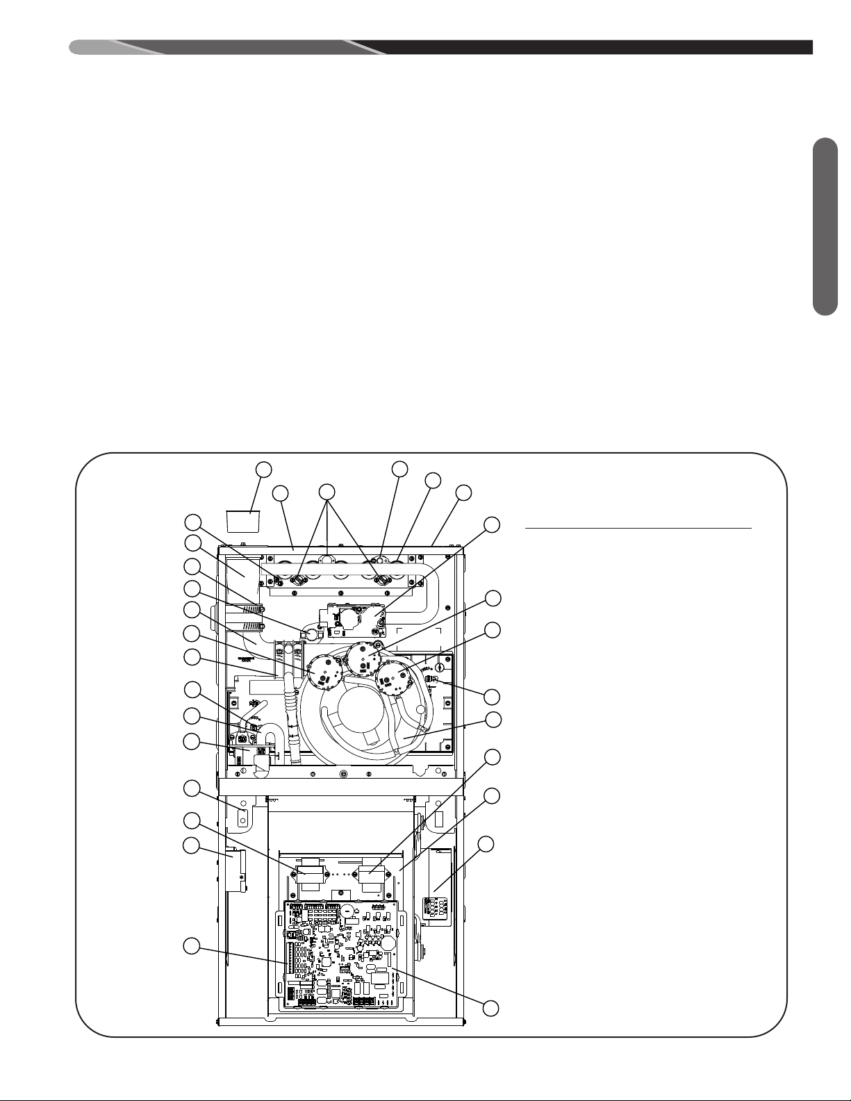
FIGURE 1
FURNACE COMPONENTS
ITEM
NO. DESCRIPTION
1. CONDENSATE TRAP
2. DOOR SWITCH
3. JUNCTION BOX
4. TRANSFORMER
5. WATER SENSOR (2)
6. PRESSURE SWITCH STAGES
A. HIGH
B. MEDIUM
C. LOW
7. EXHAUST TRANSITION
8. COUPLING (ELBOW TO TRANSITION)
9. EXHAUST
10. SHIPPING PLUG
11. FLAME SENSOR
12. OVER TEMPERATURE SWITCH
13. TOP PLATE
14. BURNER
15. IGNITER
16. COMBUSTION AIR INLET
17. GAS VALVE
18. INDUCED DRAFT BLOWER (IDB)
19. POWER FACTOR CORRECTION CHOKE
(PFC) (NOT USED ON THE 60K BTU
AND 70K BTU)
20. CONTROL MOUNTING PLATE
21. BLOWER
22. LOW VOLTAGE TERMINAL
23. COUPLING (IDB TO ELBOW)
24. MAIN LIMIT
25. FURNACE CONTROL
26. AUXILIARY TRAP
ST-A1194-67-00
3

GENERAL INFORMATION (cont.)
In Canada installations must comply with CSA B149.1.
Install units in Canada in accordance with CSA-B149,
ocal installation codes and authorities having jurisdiction.
l
CSA-B149.1 is available from:
CSA INTERNATIONAL
5060 Spectrum Way
Mississauga, Ontario
Canada L4W 5N6
online: www.csa.ca
General Information
NOTICE: Any equipment immersed in water (including by
flooding) must be replaced. Equipment and products immersed in water will have operation adversely affected
thereby voiding the warranty.
RECEIVING
Immediately upon receipt, all cartons and contents should
be inspected for transit damage. Units with damaged cartons should be opened immediately. If damage is found, it
should be noted on the delivery papers, and a damage
claim filed with the last carrier.
• After unit has been delivered to job site, remove carton
taking care not to damage unit.
• Check the unit rating plate to be sure equipment
matches job specifications.
• Read the entire instructions before starting the installation.
• Install the unit in such a way as to allow necessary access for service.
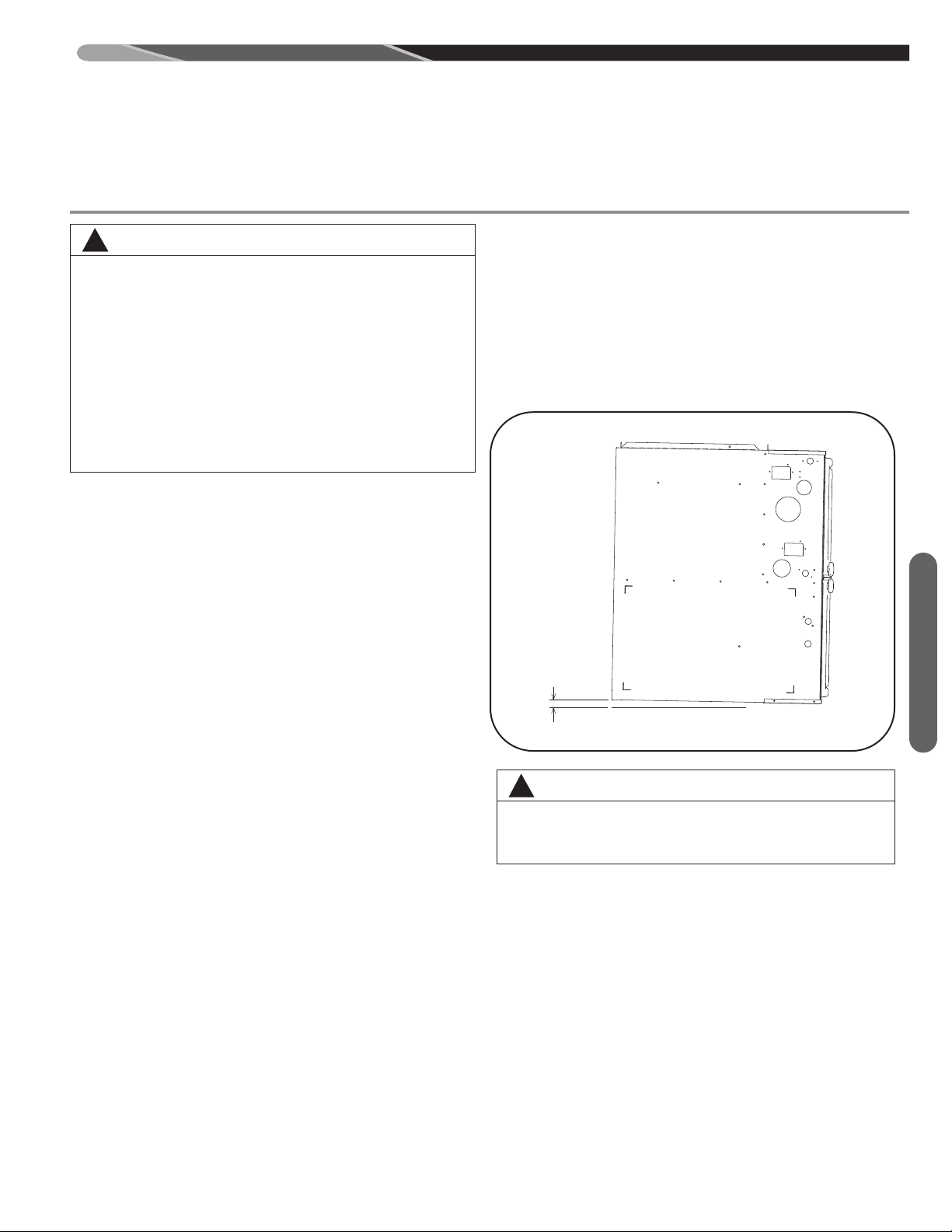
• Always remove the solid metal base pan from the top of
the furnace. The base pan is installed in this location for
shipping purposes only and should never remain in the
as-shipped location after installation.
• Install the unit with a 1/4” to 1/2” forward slope (toward
front) to ensure proper drainage.
• Install the unit in accordance with any local code which
may apply and the national codes. Latest editions are
available from: “National Fire Protection Association,
Inc., Batterymarch Park, Quincy, MA 02269.” These
publications are:
• ANSI/NFPA No. 70-(Latest Edition) National Electrical
Code.
• NFPA90A Installation of Air Conditioning and Ventilating Systems.
• NFPA90B Installation of warm air heating and air conditioning systems.
• In Canada CSA 22.2 Canadian Electrical Code.
• In Canada CSA B149.1; Canadian Natural Gas and
Propane Installation Code.
CALIFORNIA RESIDENTS ONLY
IMPORTANT: All manufacturer products meet current
Federal OSHA Guidelines for safety. California Proposition
65 warnings are required for certain products, which are
not covered by the OSHA standards.
California's Proposition 65 requires warnings for products
sold in California that contain, or produce, any of over 600
listed chemicals known to the State of California to cause
cancer or birth defects such as fiberglass insulation, lead
in brass, and combustion products from natural gas.
All “new equipment” shipped for sale in California will have
labels stating that the product contains and/or produces
Proposition 65 chemicals. Although we have not changed
our processes, having the same label on all our products
facilitates manufacturing and shipping. We cannot always
know “when, or if” products will be sold in the California
market.
You may receive inquiries from customers about chemicals found in, or produced by, some of our heating and airconditioning equipment, or found in natural gas used with
some of our products. Listed below are those chemicals
and substances commonly associated with similar equipment in our industry and other manufacturers.
• Glass Wool (Fiberglass) Insulation
• Carbon Monoxide (CO)
• Formaldehyde
• Benzene
More details are available at the Websites for OSHA (Occupational Safety and Health Administration), at
www.osha.gov and the State of California's OEHHA (Office of Environmental Health Hazard Assessment), at
www.oehha.org. Consumer education is important since
the chemicals and substances on the list are found in our
daily lives. Most consumers are aware that products present safety and health risks, when improperly used, handled and maintained.
EFFICIENCY TESTING NOTICE
For purposes of verifying or testing efficiency ratings, the
test procedure in Title 10 APPENDIX N to Subpart B of
Part 430 (Uniform Test Method for Measuring the Energy
Consumption of Furnaces and Boilers) and the clarifying
provisions provided in the AHRI Operations Manual for
Residential Furnaces that were applicable at the date of
manufacture should be used for test set up and performance.
4

Installation Instructions remain with the furnace as a reference guide to the servicing contractor. We recommend
that performance and installation data be recorded for future reference on this sheet to meet service and warranty
obligations so that job site information is available when required.
Installation Checklist
REFER TO INSTALLATION INSTRUCTIONS
GAS SUPPLY
______ Correct pipe size (record size)
______ Correct supply pressure (during furnace operation)
______ (record pressure)
______ Low fire manifold pressure (see page 52 for
instructions)
______ High fire manifold pressure (see page 53 for
instructions)
______ No gas leaks
______ L.P. Kit Number (if applicable) (record kit number)
ELECTRICAL
______ 115 V.A.C. supply (Dedicated Circuit)
(record voltage)
______ Polarity observed
______ Furnace properly grounded
______ Correct wire size (record type and gauge)
FURNACE INSTALLATION
______ Correct clearance to combustibles (record
______ clearance)
______ Correct clearance for service (at front) (record
______ clearance)
DUCT STATIC PRESSURE
______ no. of elbows – intake air (record number of
______ elbows)
______ ft. of pipe – exhaust pipe (record length)
______ no. of elbows – exhaust pipe (record number of
______ elbows)
______ Exhaust Vent Temperature (record temperature)
TERMINATIONS – DIRECT VENT
VERTICAL
______ Intake – 12" [305mm] min. above roof/snow level
(record height above anticipated snow level)
or, in Canada, intake and exhaust vents conform
with CSA B149.1; Canadian Natural Gas and
Propane Installation Code
______ Correct relationship – exhaust to intake
HORIZONTAL/VERTICAL – CONCENTRIC (RXGY-E03A)
______ Intake – 12" [305mm] min. above roof/snow level
(record height above anticipated snow level)
or, in Canada, intake and exhaust vents conform
with CSA B149.1; Canadian Natural Gas and
Propane Installation Code
______ Exhaust sloped down toward furnace
______ Correct distances (horizontal and vertical) –
exhaust to intake
______ 12" [305mm] min. above grade/snow level (record
height above anticipated snow level) or, in
Canada, intake and exhaust vents conform
with CSA B149.1; Canadian Natural Gas and
Propane Installation Code
General Information
______ in. w.c. on heating speed (record static pressure)
______ in. w.c. on cooling speed (record static pressure)
______ Air temperature rise in heat (record air temperature
______ rise)
______ Air temperature rise in cool (record air temperature
______ rise)
CONDENSATE LINE
______ Trap filled with water
______ Vented
______ Sloped toward drain
______ Condensate drain line hoses connected and
______ clamped
______ Freeze protection (if necessary)
VENTING – DIRECT VENT
______ in. diameter – intake pipe (record diameter)
______ in. diameter – exhaust pipe (record diameter)
______ ft. of pipe – intake air (record length)
______ Above anticipated snow level (record maximum
______ anticipated snow level)
VENTING – NON-DIRECT VENT (Vertical Venting
Only)
______ in. diameter – exhaust pipe (record diameter)
______ ft. of pipe – exhaust (record length)
______ no. of elbows (record number of elbows)
TERMINATION – NON-DIRECT VENT
VERTICAL
______ 12" [305mm] min. above roof/snow level (record
height above anticipated snow level) or, in
Canada, intake and exhaust vents conform
with CSA B149.1; Canadian Natural Gas and
Propane Installation Code
5
SAFETY INFORMATION
WARNING
!
DO NOT INSTALL THIS FURNACE IN A MOBILE HOME!!
THIS FURNACE IS NOT APPROVED FOR INSTALLATION
IN A MOBILE HOME. DOING SO COULD CAUSE FIRE,
PROPERTY DAMAGE, PERSONAL INJURY OR DEATH.
WARNING
!
INSTALL THIS FURNACE ONLY IN A LOCATION AND POSITION AS SPECIFIED IN THE LOCATION REQUIREMENTS AND CONSIDERATIONS SECTION OF THESE
INSTRUCTIONS.
WARNING
!
IMPROPER INSTALLATION, OR INSTALLATION NOT
MADE IN ACCORDANCE WITH THE CSA INTERNATIONAL
(CSA) CERTIFICATION OR THESE INSTRUCTIONS, CAN
RESULT IN UNSATISFACTORY OPERATION AND/OR
DANGEROUS CONDITIONS AND ARE NOT COVERED BY
THE MANUFACTURER’S WARRANTY.
Safety Information
WARNING
!
DO NOT BYPASS, JUMPER, OR REMOVE ANY SAFETY
SWITCH FROM THE FURNACE CONTROL CIRCUIT. IF A
SAFETY SWITCH CAUSES THE FURNACE TO SHUT
DOWN OR OPERATE INTERMITTENTLY, IT IS AN INDICATION OF A POTENTIAL SAFETY HAZARD THAT MUST
BE ADDRESSED BY A QUALIFIED TECHNICIAN, SERVICE AGENCY OR THE GAS SUPPLIER. DO NOT RESET
SAFETY CONTROLS WITHOUT CORRECTIVE ACTION
AND/OR VERIFICATION OF PROPER SAFE OPERATION
BY A QUALIFIED INSTALLER, SERVICE AGENCY OR
THE GAS SUPPLIER.
REPLACE ANY SAFETY CONTROL COMPONENT ONLY
WITH IDENTICAL OEM REPLACEMENT PARTS. WHEN A
NEW SAFETY SWITCH IS INSTALLED, IT MUST BE
TESTED FOR A MINIMUM OF 15 MINUTES WITH THE
FURNACE OPERATING AT MAXIMUM INPUT RATE AND
WITH BOTH BLOWER AND BURNER DOOR INSTALLED.
IF THE FURNACE IS INSTALLED IN A CLOSET, THE
CLOSET DOOR MUST ALSO BE CLOSED FOR THIS
TEST. REPEAT THE TEST AT THE MINIMUM INPUT RATE
IF THE FURNACE IS A MULTI-STAGE FURNACE.
WARNING
!
USE ONLY WITH THE TYPE OF GAS APPROVED FOR
THIS FURNACE. REFER TO THE FURNACE RATING
PLATE.
WARNING
!
NEVER TEST FOR GAS LEAKS WITH AN OPEN FLAME.
USE A COMMERCIALLY AVAILABLE SOAP SOLUTION
MADE SPECIFICALLY FOR THE DETECTION OF LEAKS
TO CHECK ALL CONNECTIONS, AS SPECIFIED IN GAS
SUPPLY AND PIPING SECTION OF THESE INSTRUCTIONS.
WARNING
!
COMBUSTION AND VENTILATION AIR MUST BE PROVIDED TO THE FURNACE AS REQUIRED BY THE NATIONAL FUEL-GAS CODE (U.S.) AND CSA B149.1
(CANADA) AND THE COMBUSTION AND VENTILATION
AIR SECTION OF THESE INSTRUCTIONS.
WARNING
!
COMBUSTION PRODUCTS MUST BE DISCHARGED OUTDOORS. CONNECT THIS FURNACE TO AN APPROVED
VENT SYSTEM ONLY, AS SPECIFIED IN THE VENT PIPE
INSTALLATION SECTION OF THESE INSTRUCTIONS.
WARNING
!
WHEN A FURNACE IS INSTALLED SO THAT SUPPLY
DUCTS CARRY AIR CIRCULATED BY THE FURNACE TO
AREAS OUTSIDE THE SPACE CONTAINING THE FURNACE, THE RETURN AIR SHALL ALSO BE HANDLED BY
DUCT(S) SEALED TO THE FURNACE CASING AND TERMINATING OUTSIDE THE SPACE CONTAINING THE FURNACE.
WARNING
!
WHENEVER THE FACTORY RETURN-AIR CONNECTION
IS NOT USED IT MUST BE SEALED. A SOLID METAL
BASE PLATE MUST BE INSTALLED AND SEALED. FACTORY BASE PLATES ARE AVAILABLE AS ACCESSORY
ITEMS. (PART NUMBERS ARE LISTED IN THE SPEC
SHEET FOR THE FURNACE.) FAILURE TO INSTALL AND
SEAL THE BASE PLATE AND RETURN AIR DUCT CONNECTIONS MAY ALLOW CARBON MONOXIDE AND
OTHER CONTAMINANTS TO BE DRAWN INTO THE CONDITIONED AIR SPACE AND DISTRIBUTED THROUGHOUT
THE HEATED SPACE.
WARNING
!
DO NOT OPERATE THE SYSTEM WITHOUT FILTERS. A
PORTION OF THE DUST ENTRAINED IN THE AIR MAY
TEMPORARILY LODGE IN THE AIR DUCT RUNS AND AT
THE SUPPLY REGISTERS. ANY CIRCULATED DUST PARTICLES WILL BE HEATED AND CHARRED BY CONTACT
WITH THE FURNACE HEAT EXCHANGER. THIS SOOTY
RESIDUE WILL SOIL CEILINGS, WALLS, DRAPES, CARPETS AND OTHER HOUSEHOLD ARTICLES. SOOT DAMAGE MAY ALSO RESULT WITH, OR WITHOUT, FILTERS IN
PLACE, WHEN CERTAIN TYPES OF CANDLES ARE
BURNED, OR CANDLEWICKS ARE LEFT UNTRIMMED.
WARNING
!
IN COMPLIANCE WITH RECOGNIZED CODES, IT IS RECOMMENDED THAT AN AUXILIARY DRAIN PAN BE INSTALLED UNDER THIS FURNACE AND ANY INSTALLED
EVAPORATOR COIL THAT IS LOCATED IN ANY AREA OF
A STRUCTURE WHERE DAMAGE TO THE BUILDING OR
BUILDING CONTENTS MAY OCCUR AS A RESULT OF AN
OVERFLOW OF THE FURNACE CONDENSATE DISPOSAL SYSTEM OR THE COIL DRAIN PAN OR A STOPPAGE IN THE PRIMARY CONDENSATE DRAIN PIPING.
6
SAFETY
WARNING
!
ALWAYS INSTALL THE FURNACE TO OPERATE WITHIN
THE FURNACE’S INTENDED TEMPERATURE-RISE
RANGE WITH A DUCT SYSTEM WHICH HAS AN EXTERNAL STATIC PRESSURE WITHIN THE ALLOWABLE
RANGE, AS SPECIFIED IN THE DUCTING SECTION OF
THESE INSTRUCTIONS. SEE ALSO FURNACE RATING
PLATE.
THE FURNACE MAY BE USED FOR HEATING OF BUILDINGS OR STRUCTURES UNDER CONSTRUCTION.
INSTALLATION MUST COMPLY WITH ALL INSTALLATION
INSTRUCTIONS INCLUDING:
PROPER VENT INSTALLATION;
-
FURNACE OPERATING UNDER THERMOSTATCONTROL;
RETURN AIR DUCT SEALED TO THE FURNACE;
-
AIR FILTERS IN PLACE;SET FURNACE INPUT RATE AND TEMPERA-TURE RISE PER RATING PLATE MARKINGS;
MEANS FOR PROVIDING OUTDOOR AIR RE-
-
QUIRED FOR COMBUSTION;
RETURN AIR TEMPERATURE MAINTAINED BE-
-
TWEEN 55°F (13°C) AND 80°F (27°C); AND
CLEAN FURNACE, DUCT WORK AND COMPO-
-
NENTS UPON SUBSTANTIAL COMPLETION OF
THE CONSTRUCTION PROCESS, AND VERIFY
THAT THE FURNACE OPERATING CONDITIONS
INCLUDING IGNITION, INPUT RATE, TEMPERATURE RISE AND VENTING, ACCORDING TO THE
INSTRUCTIONS AND CODES.
IMPORTANT
!
CANADIAN INSTALLATIONS
GAS FURNACES MANUFACTURED ON OR AFTER MAY
1, 2017 ARE NOT PERMITTED TO BE USED IN CANADA
FOR HEATING OF BUILDINGS OR STRUCTURES UNDER
CONSTRUCTION.
IMPORTANT INFORMATION
ABOUT EFFICIENCY AND
WARNING
!
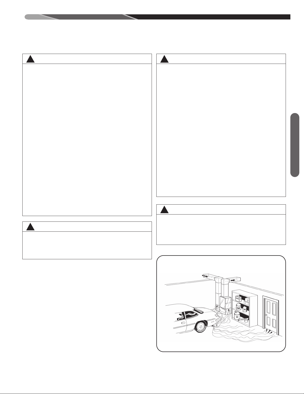
DUCT LEAKS CAN CREATE AN UNBALANCED SYSTEM
AND DRAW POLLUTANTS SUCH AS DIRT, DUST, FUMES
AND ODORS INTO THE HOME CAUSING PROPERTY
DAMAGE. FUMES AND ODORS FROM TOXIC, VOLATILE
OR FLAMMABLE CHEMICALS, AS WELL AS AUTOMOBILE EXHAUST AND CARBON MONOXIDE (CO), CAN BE
DRAWN INTO THE LIVING SPACE THROUGH LEAKING
UCTS AND UNBALANCED DUCT SYSTEMS CAUSING
D
PERSONAL INJURY OR DEATH (SEE FIGURE 2).
• IF AIR-MOVING EQUIPMENT OR DUCTWORK IS LOCATED IN GARAGES OR OFF-GARAGE STORAGE
AREAS - ALL JOINTS, SEAMS, AND OPENINGS IN THE
EQUIPMENT AND DUCT MUST BE SEALED TO LIMIT
THE MIGRATION OF TOXIC FUMES AND ODORS INCLUDING CARBON MONOXIDE FROM MIGRATING
INTO THE LIVING SPACE.
• IF AIR-MOVING EQUIPMENT OR DUCTWORK IS LOCATED IN SPACES CONTAINING FUEL BURNING APPLIANCES SUCH AS WATER HEATERS OR BOILERS ALL JOINTS, SEAMS, AND OPENINGS IN THE EQUIPMENT AND DUCT MUST ALSO BE SEALED TO PREVENT DEPRESSURIZATION OF THE SPACE AND
POSSIBLE MIGRATION OF COMBUSTION BYPRODUCTS INCLUDING CARBON MONOXIDE INTO THE LIVING SPACE.
WARNING
!
BLOWER AND BURNERS MUST NEVER BE OPERATED
WITHOUT THE BLOWER DOOR IN PLACE. THIS IS TO
PREVENT DRAWING GAS FUMES (WHICH COULD CONTAIN HAZARDOUS CARBON MONOXIDE) INTO THE
HOME THAT COULD RESULT IN PERSONAL INJURY OR
DEATH.
FIGURE 2
MIGRATION OF DANGEROUS SUBSTANCES, FUMES, AND ODORS INTO
LIVING SPACES
Safety Information
INDOOR AIR QUALITY
Central cooling and heating equipment is only as efficient
as the duct system that carries the cooled or heated air.
To maintain efficiency, comfort and good indoor air quality, it is important to have the proper balance between the
air supplied to each room and the air returning to the
cooling and heating equipment.
Proper balance and sealing of the duct system improves
the efficiency of the heating and air conditioning system
and improves the indoor air quality of the home by reducing the amount of airborne pollutants that enter homes
from spaces where the ductwork and / or equipment is
located. The manufacturer and the U.S. Environmental
Protection Agency’s Energy Star Program recommend
that central duct systems be checked by a qualified contractor for proper balance and sealing.
Adapted from Residential Duct Diagnostics and Repair, with permission of Air Conditioning
Contractors of America (ACCA).
7

COMMONWEALTH OF MASSACHUSETTS NOTE
IMPORTANT! THE COMMONWEALTH OF MASSACHUSETTS REQUIRES COMPLIANCE WITH REGULATION
248 CMR 4.00 AND 5.00 FOR INSTALLATION OF
THROUGH-THE-WALL VENTED GAS APPLIANCES AS
FOLLOWS:
(a) For all side wall horizontally vented gas fueled equipment installed in every dwelling, building or structure used
in whole or in part for residential purposes, including
those owned or operated by the Commonwealth and
where the side wall exhaust vent termination is less than
seven (7) feet above finished grade in the area of the
venting, including but not limited to decks and porches,
the following requirements shall be satisfied:
1. INSTALLATION OF CARBON MONOXIDE DETECTORS. At the time of installation of the side wall horizon-
tal vented gas fueled equipment, the installing plumber or
gasfitter shall observe that a hard wired carbon monoxide
detector with an alarm and battery back-up is installed on
the floor level where the gas equipment is to be installed.
In addition, the installing plumber or gasfitter shall ob-
Safety Information
serve that a battery operated or hard wired carbon
monoxide detector with an alarm is installed on each additional level of the dwelling, building or structure served
by the side wall horizontal vented gas fueled equipment.
It shall be the responsibility of the property owner to secure the services of qualified licensed professionals for
the installation of hard wired carbon monoxide detectors.
a. In the event that the side wall horizontally vented gas
fueled equipment is installed in a crawl space or an attic,
the hard wired carbon monoxide detector with alarm and
battery back-up may be installed on the next adjacent floor
level.
b. In the event that the requirements of this subdivision
can not be met at the time of completion of installation,
the owner shall have a period of thirty (30) days to comply
with the above requirements; provided, however, that during said thirty (30) day period, a battery operated carbon
monoxide detector with an alarm shall be installed.
2. APPROVED CARBON MONOXIDE DETECTORS.
Each carbon monoxide detector as required in accordance with the above provisions shall comply with NFPA
720 and be ANSI/UL 2034 listed and IAS certified.
3. SIGNAGE. A metal or plastic identification plate shall
be permanently mounted to the exterior of the building at
a minimum height of eight (8) feet above grade directly in
line with the exhaust vent terminal for the horizontally
vented gas fueled heating appliance or equipment. The
sign shall read, in print size no less than one-half (1/2)
inch in size, “GAS VENT DIRECTLY BELOW. KEEP
CLEAR OF ALL OBSTRUCTIONS”.
4. INSPECTION. The state or local gas inspector of the
side wall horizontally vented gas fueled equipment shall
ot approve the installation unless, upon inspection, the
n
inspector observes carbon monoxide detectors and signage installed in accordance with the provisions of 248
CMR 5.08(2)(a) 1 through 4.
(b) EXEMPTIONS: The following equipment is exempt
from 248 CMR 5.08(2)(a)1 through 4:
1. The equipment listed in Chapter 10 entitled “Equipment
Not Required To Be Vented” in the most current edition of
NFPA 54 as adopted by the Board; and
2. Product Approved side wall horizontally vented gas fueled equipment installed in a room or structure separate
from the dwelling, building or structure used in whole or in
part for residential purposes.
(c) MANUFACTURER REQUIREMENTS – GAS EQUIPMENT VENTING SYSTEM PROVIDED. When the manufacturer of Product Approved side wall horizontally vented
gas equipment provides a venting system design or venting system components with the equipment, the instructions provided by the manufacturer for installation of the
equipment and the venting system shall include:
1. Detailed instructions for the installation of the venting
system design or the venting system components; and
2. A complete parts list for the venting system design or
venting system.
(d) MANUFACTURER REQUIREMENTS – GAS EQUIPMENT VENTING SYSTEM NOT PROVIDED. When the
manufacturer of a Product Approved side wall horizontally
vented gas fueled equipment does not provide the parts
for venting the flue gases, but identifies “special venting
systems”, the following requirements shall be satisfied by
the manufacturer:
1. The referenced “special venting system” instructions
shall be included with the appliance or equipment installation instructions; and
2. The “special venting systems” shall be Product Approved by the Board, and the instructions for that system
shall include a parts list and detailed installation instructions.
(e) A copy of all installation instructions for all Product Approved side wall horizontally vented gas fueled equipment, all venting instructions, all parts lists for venting
instructions, and/or all venting design instructions shall remain with the appliance or equipment at the completion of
the installation.
8
1/4" MIN. TO 1/2" MAX. TILT
TOWARD THE FRONT
OF THE CABINET IN ALL
INSTALLATIONS AND
O
RIENTATIONS
UPFLOW / DOWNFLOW
LOCATION REQUIREMENTS
GENERAL INFORMATION
1. IMPORTANT: If installing the unit over a finished ceil-
2. IMPORTANT: If using a cooling evaporator coil with
If these are manual dampers, they must be equipped to
prevent heating or cooling operation unless the damper is
in the full heat or cool position.
3. IMPORTANT: Furnace must be installed level from
NOTE: These furnaces are approved for installation in attics, as well as alcoves, utility rooms, closets and crawlspaces. Provisions must be made to prevent freezing of
condensate.
FREEZE PROTECTION
For installations where the furnace may reach temperatures below 32°F (0°C) (such as an alcove or attic installation), the installer must take precautions to ensure that the
drain trap and connected drain pipe do not freeze. Local
codes and practices should be followed in order to prevent
freezing.
If the drain trap is installed within the furnace cabinet, no
freeze protection is required. When the trap is mounted
outside or partially outside the cabinet, it must be protected from freezing. Regardless of the location of the
drain trap, any exposed drain piping must be protected
from freezing as required by local practices or codes. A UL
WARNING
!
WHEN THIS FURNACE IS INSTALLED IN A RESIDENTIAL GARAGE, IT MUST BE INSTALLED SO
THE BURNERS AND IGNITION SOURCE ARE LOCATED NO LESS THAN 18 INCHES [450MM] ABOVE
THE FLOOR. THIS IS TO PREVENT THE RISK OF IGNITING FLAMMABLE VAPORS WHICH MAY BE
PRESENT IN A GARAGE. ALSO, THE FURNACE
MUST BE LOCATED OR PROTECTED TO AVOID
PHYSICAL DAMAGE BY VEHICLES. FAILURE TO
FOLLOW THESE WARNINGS CAN CAUSE A FIRE
OR EXPLOSION, RESULTING IN PROPERTY DAMAGE, PERSONAL INJURY OR DEATH.
ing or living area, be certain to install an auxiliary condensate drain pan under the entire unit. This auxiliary
drain pan should extend under any evaporator coil installed with the furnace and the open portion of the
condensate drain assembly. See “Condensate
Drain/Neutralizer” section for more details.
this furnace, be sure the air passes over the heat exchanger before passing over the cooling coil. The
cooled air passing over the warm ambient air inside
the heat exchanger tubes can cause condensation inside the tubes resulting in corrosion and eventual failure.
front-to-back or with a slight tilt such that the back of
the furnace is up to 1/2” higher than the front of the
furnace as shown in Figure 3.
or CSA listed heat tape or UL or CSA approved heating
cable with a rating of 3-6 watts per foot is acceptable protection when installed and maintained in accordance with
the manufacturer’s instructions. Good installation practices
necessitate that the installer verify heat tape operation in
accordance with the manufacturer’s instructions at the
time of installation.
IMPORTANT: Support this unit when installed. Since this
furnace is suitable for attic or crawl space installation, it
may be installed on combustible wood flooring or by using
support brackets as required.
FIGURE 3
BACK FRONT
0-1/2( HIGHER
THAN FRONT
OF FURNACE
WARNING
!
UPFLOW
ST-A1194-13-X0
THIS FURNACE IS NOT APPROVED OR RECOMMENDED FOR INSTALLATION ON ITS BACK, WITH
ACCESS DOORS FACING UPWARDS.
SITE SELECTION
1. Select a site in the building near the center of the proposed, or existing, duct system.
2. Give consideration to the vent system piping when selecting the furnace location. Be sure the venting system can get from the furnace to the termination with
minimal length and elbows.
3. Locate the furnace near the existing gas piping. Or, if
running a new gas line, locate the furnace to minimize
the length and elbows in the gas piping.
4. Locate the furnace to maintain proper clearance to
combustibles as shown in following Figure 5.
Location
9
6” 8”
OPTION - A
2” PIPE
OPTION - B
2”-3” PIPE
C
LOCATION REQUIREMENTS
GENERAL INFORMATION (cont.)
WARNING
!
DO NOT LIFT THE UNIT BY THE HEAT EXCHANGER TUBES. DOING SO CAN DAMAGE THE
HEAT EXCHANGER ASSEMBLY.
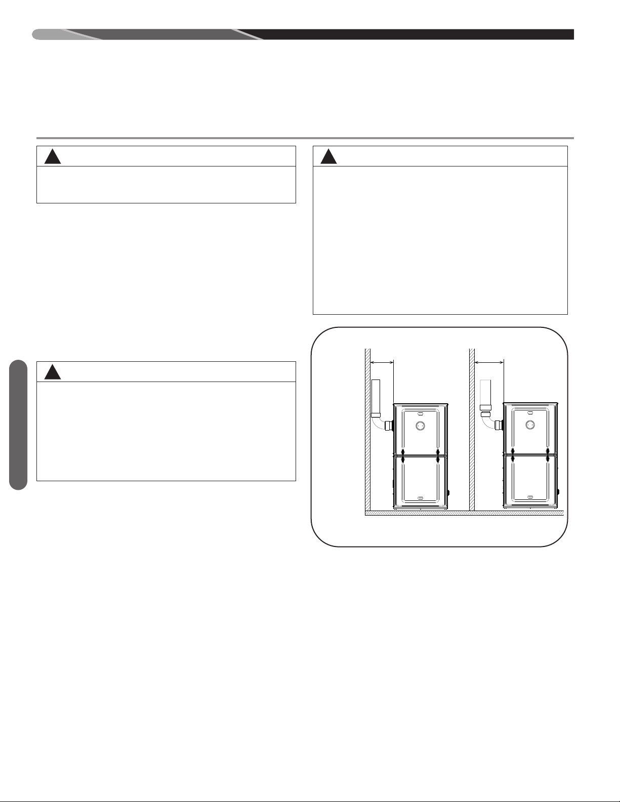
CLEARANCE – ACCESSIBILITY
The design of forced air furnaces with input ratings as
listed in the tables under Figure 5 are certified by CSA-International for the clearances to combustible materials
shown in inches.
See name/rating plate and clearance label for specific
model number and clearance information.
Service clearance of at least 24” (61 cm) is recommended
in front of all furnaces.
NOTE: Use recommended 24” (61 cm) clearance if accessibility clearances are greater than fire protection clearances.
WARNING
!
UPFLOW FURNACES ARE DESIGNFOR INSTALLATION ON COMBUSTIBLE FLOORS.
NOTE, HOWEVER, THAT FURNACES MUST NOT
BE INSTALLED DIRECTLY ON CARPETING, TILE
OR OTHER COMBUSTIBLE MATERIAL OTHER
THAN WOOD FLOORING. INSTALLATION ON A
Location
COMBUSTIBLE MATERIAL CAN RESULT IN FIRE,
CAUSING PROPERTY DAMAGE, PERSONAL INJURY OR DEATH.
CERTIFIED
WARNING
!
COMBUSTIBLE MATERIAL MUST NOT BE
PLACED ON OR AGAINST THE FURNACE
JACKET. THE AREA AROUND THE FURNACE
MUST BE KEPT CLEAR AND FREE OF ALL COMBUSTIBLE MATERIALS INCLUDING GASOLINE
AND OTHER FLAMMABLE VAPORS AND LIQUIDS. PLACEMENT OF COMBUSTIBLE MATERIALS ON, AGAINST OR AROUND THE FURNACE
JACKET CAN CAUSE AN EXPLOSION OR FIRE
RESULTING IN PROPERTY DAMAGE, PERSONAL
INJURY OR DEATH. THE HOMEOWNER SHOULD
BE CAUTIONED THAT THE FURNACE AREA
MUST NOT BE USED AS A BROOM CLOSET OR
FOR ANY OTHER STORAGE PURPOSES.
FIGURE 4
NOTE: THESE
DIMENSIONS
REFER TO
FURNACE
CLEARANCE
ONLY. FOR REQUIRED VENT
CLEARANCES
AND SUPPORTS, REFER
TO VENT MANUFACTURER’S
INSTRUCTIONS.
CLEARANCE FLUE VENT TO WALL
10
NOTE: THESE ILLUSTRATIONS ARE INTENTIONALLY GENERIC.
NOTE: SOME PARTS OF YOUR FURNACE MAY APPEAR DIFFERENT.
ST-A1194-86-00
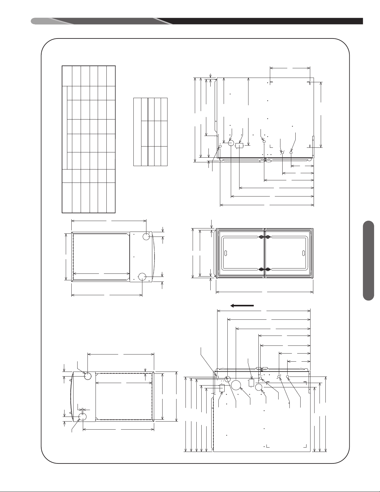
FIGURE 5
TOPBOTTOM
FRONTLEFT SIDE RIGHT SIDE
RIGHT BACK TOP FRONT VENT
(-)97VA060
(-)(-)97MDV060
(-)97VA070
(-)(-)97MDV070
(-)97VA085
(-)(-)97MDV085
(-)97VA100
(-)(-)97MDV100
(-)97VA115
(-)(-)97MDV115
0 0 0 1 2 0
0 0 0 1 2 0
0 0 0 1 2 0
SHIPPING
WEIGHTS
MINIMUM CLEARANCE (IN.)
MODEL
LEFT
SIDE
UNIT DIMENSIONS
(CLEARANCE TO COMBUSTIBLES)
A
I
R
F
L
O
W
A
B
.62
.62
34.00
23.33
25.44
26.19
22.63
25.81
26.31
8.00
11.03
17.50
18.13
26.11
29.05
32.65
24.19
22.31
OPTIONAL TRAP
LOCATION
(HORIZONTAL)
OPTIONAL CONDENSATE
DRAIN (DOWNFLOW)
GAS
CONNECTION
OPTIONAL COMBUSTION
VENT LOCATION
OPTIONAL TRAP
LOCATION
(HORIZONTAL)
OPTIONAL VENT
AIR INLET
CONDENSATE DRAIN
(UPFLOW)
ELECTRICAL CONNECTION
LINE VOLTAGE
ELECTRICAL CONNECTION
LOW VOLTAGE
22.96
23.80
8.00
11.00
17.44
29.05
26.17
32.88
23.00
14.00
28.06
1.12
29.62
.62
19.83
OPTIONAL LINE VOLTAGE
WIRING
OPTIONAL LOW VOLTAGE
WIRING
OPTIONAL CONDENSATE
DRAIN (UPFLOW)
TRAP LOCATION
(HORIZONTAL)
OPTIONAL
GAS CONNECTION
OPTIONAL
CONDENSATE DRAIN
(DOWNFLOW)
1.76
1.66
24.86
26.26
B
19.83
SUPPLY
AIR
23.21
1.62
1.67
24.91
.30
C
19.77
A
.65
RETURN
AIR
OPTIONAL
VENT OUTLET
KNOCKOUT
OPTIONAL COMBUSTION
AIR INLET KNOCKOUT
SUPPLY AND RETURN DEPICTED AS UPFLOW CONFIGURATION.
FLANGE CONFIGURATION WILL VARY DEPENDING ON IN STALLATION ORI ENTATION.
A B C
17 1/2 16 17/64 16 13/64
21 19 49/64 19 45/64
24 1/2 23 17/64 23 13/64
FLANGE DIMENSIONS
*A SERVICE CLEARANCE OF AT LEAST 24” IS RECOMMENDED IN FRONT OF ALL FURNACES
0 0 0 1 2 0
0 0 0 1 2 0
UNIT DIMENSIONS (CLEARANCE TO COMBUSTIBLES – SOME MEASUREMENTS DO NOT APPLY TO UPFLOWS)
ST-A1194-01-X0
Location
11
FIELD CONVERSIONS
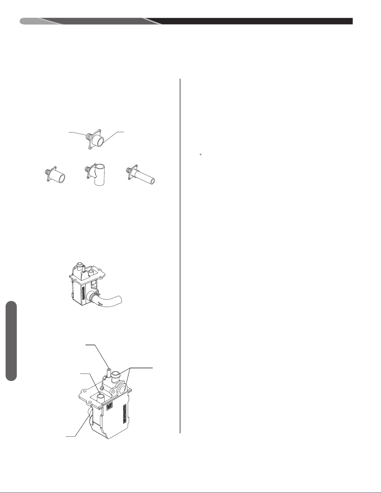
CONDENSATE PVC/HOSE OPTIONS
B
ULKHEAD COUPLING
CONDENSATE DRAINIAGE HAS OPTIONS FOR 3/4" OR 1/2"
PVC CONNECTIONS. THE BULKHEAD COUPLING CONNECTS THE
RUBBER HOSES FROM INSIDE THE UNIT TO THE PVC PIPE
EXTERIOR OF THE UNIT. PVC PIPE CAN BE CEMENTED
DIRECTLY TO THE COUPLING AND THE TRAP WITH PROPER
PVC CEMENT AND PRIMER.
1/2" PVC
PIPE
3/4" PVC
TEE
RUBBER HOSE
CONNECTION
P
VC FITTING/PIPE
3/4" PVC
COUPLING
NOTE: IMPROPER HOSE CONNECTIONS WILL PREVENT
CONDENSATE FROM DRAINING.
CONDENSATE TRAP
THE CONDENSATE TRAP HAS 2 SIDES PLEASE NOTE THEIR
LOCATIONS FOR DRAIN CONNECTIONS DURING CONVERSION.
OUT TO DRAIN
COLLECTOR BOX
IN FROM
IN FROM FLUE
ELBOW OR COUPLING
1/4" VENT IN
FROM COLLECTOR BOX
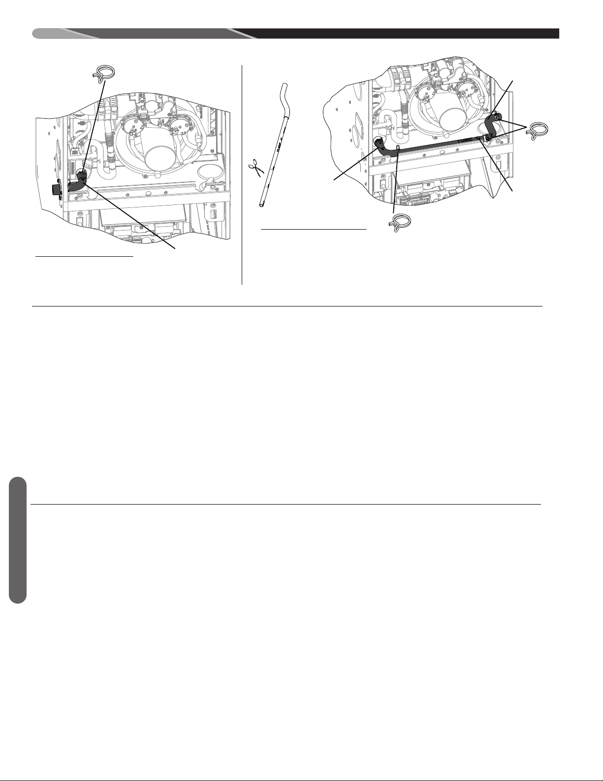
GENERAL CONVERSION INSTRUCTIONS
ST-A1194-37-02
-2010°
CONVERSION AND INSTALLATION
C
ONSIDERATIONS
ALL CONVERSIONS REQUIRE THE CONDENSATE PLUMBING TO
HAVE DECLINE IN THE DIRECTION OF THE WATER FLOW.
WHEN INSTALLING AND MOVING CONDENSATE PLUMBING THE
HOSES SHOULD BE FREE OF KINKS FOR PROPER WATER FLOW.
WHEN DRAIN HOSE OR CONDENSATE TRAP HOSE
ROUTING CHANGES ARE NECESSARY BE SURE TO PLUG OR CAP
ANY UNUSED HOSE TAPS.
THE INDUCER COUPLING COMES FROM THE FACTORY WITH
A 10
TILT FOR UP FLOW INSTALLATIONS. WHEN
CONVERTED TO DOWN FLOW THE COUPLING REQUIRES A
ROTATION A MINIMUM OF 10
FROM HORIZONTAL AS SHOWN.
HORIZONTAL INSTALLATIONS REQUIRE CONDENSATE TRAP TO BE
MOUNTED EXTERNALLY BELOW THE UNIT:
-USE CAUTION-MOUNT THE TRAP AFTER THE UNIT IS AT
THE POINT OF INSTALLATION TO PREVENT DAMAGE TO THE
TRAP DURING TRANSPORT.
-HAND TIGHTEN SCREWS WHEN MOUNTING THE TRAP OR THE
BULKHEAD COUPLING TO THE CABINET TO PREVENT DAMAGE
TO THE MOUNTING FLANGE.
-USE PROPER FREEZE PROTECTION IF REQUIRED.
-ALLOW MINIMUM OF 6" BELOW THE FURNACE FOR CLEARANCE.
10-20°
TILT ON INDUCER COUPLING
GROUND
GROUND
LEVEL
MIDLINE
WORM
DRIVE
CLAMP
COUPLING
THE WORM DRIVE FOR THE HOSE CLAMPS
USED ON THE FLUE TRANSITION COUPLING
OR THE IDB COUPLING MUST BE ABOVE THE
LEVEL MIDLINE WHEN IN THE HORIZONTAL
POSITION AS DETAILED HERE.
IF THE IDB COUPLING IS REMOVED, IT MUST BE REPLACED IN THE
PROPER ORIENTATION. AN ARROW IS PRESENT ON THE COUPLING
TO INDICATE THE DIRECTION OF EXHAUST FLOW. MAKE SURE THE
ARROW POINTS IN THE CORRECT DIRECTION.
NOTE:
T
HE CONDENSATE TRAP IS DESIGNED WITH MULTIPLE OUTLET
DRAIN CONNECTIONS THAT CAN BE UTILIZED. THE SAME OUTLET
CAN BE USED FOR BOTH STANDARD PVC AND A 5/8" RUBBER
HOSE.
WHEN THE TRAP IS LOCATED INSIDE THE UNIT A 5/8" RUBBER
HOSE CAN BE SECURED WITH A HOSE CLAMP TO MAKE HOSE
CONNECTIONS TO THE BULKHEAD COUPLING. PLIERS ARE
NEEDED TO ADJUST OR REMOVE THE CLAMP.
WHEN THE TRAP IS LOCATED OUTSIDE OF THE UNIT STANDARD
PVC FITTINGS CAN BE CEMENTED DIRECTLY TO THE OUTLET
WITH PROPER PVC CEMENT AND PRIMER.
Field Conversions
12
FIELD CONVERSIONS
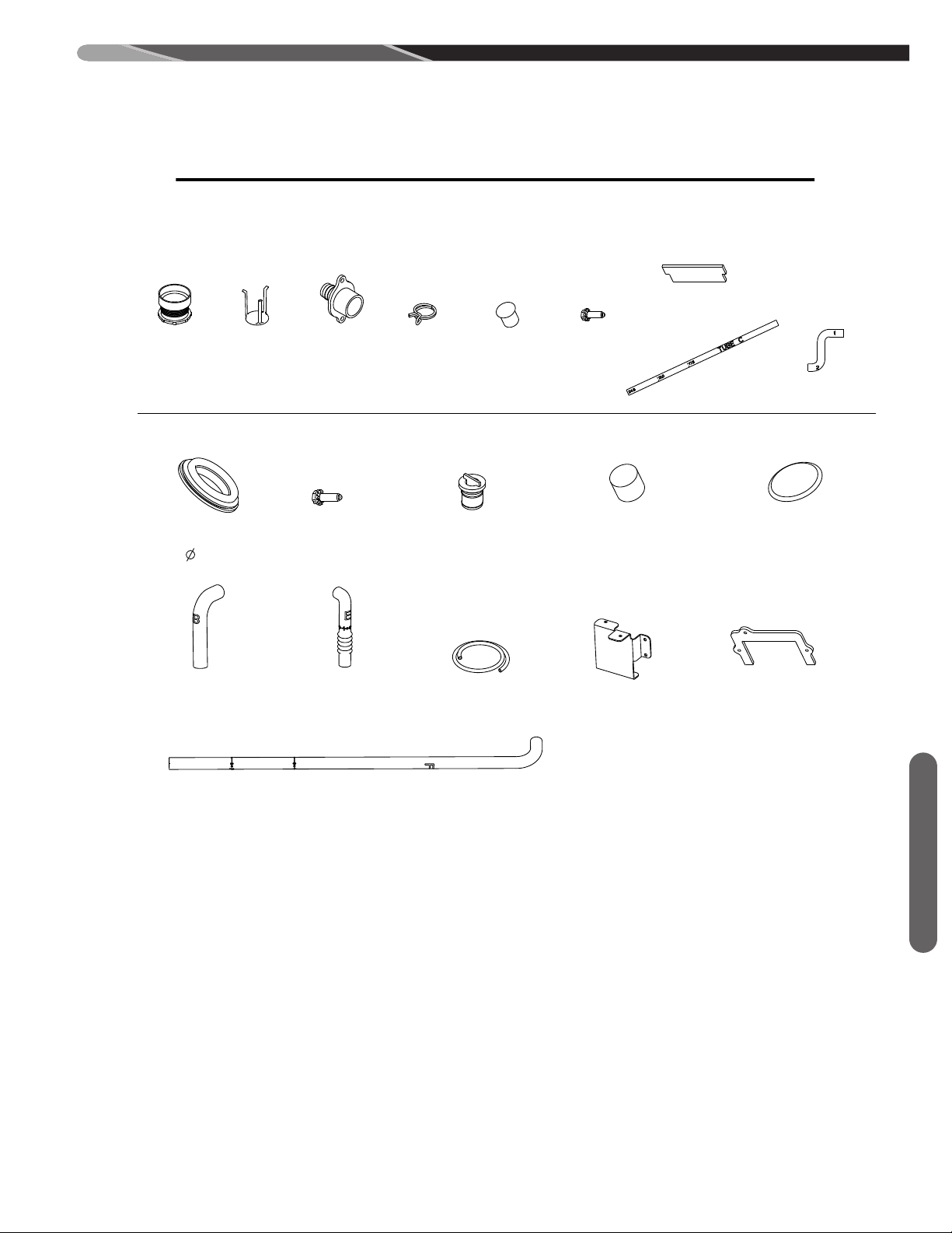
PARTS BAG (PROVIDED WITH UNIT)
CONVERSION KIT RXGY-CK
CONVERSION KIT RXGY-ZK
(X2)
2-5/8" FLUSH
MOUNT PLUG
1/2" DRAIN
HOSE E
INTAKE
C
OUPLING
.559" CONDENSATE
TRAP DRAIN PLUG
#8 X 1/2"
SCREW
(X2)
INTAKE
PIPE
1/4" BLACK
VENT TUBE
BULKHEAD
COUPLING
HOSE DOUBLE ELBOWTUBE C
HOSE CLAMP
INTAKE AIR
DIFFUSER
#8 X 1/2"
SCREW
(
X4)
#8 X 1/2"
SCREW
(X10)
5/8" DRAIN
HOSE B
CONDENSATE TRAP
BRACKET (DOWN FLOW)
2" PVC VANE
1/4" HOLE
PLUG
1/2" DRAIN
HOSE F
1/2" DRAIN
HOSE G
CONDENSATE
TRAP GASKET
2" PIPE GROMMET
(
3.375)
1/2" VINYL
CAP (YELLOW)
PIPE COLLAR
GASKET ASSEMBLY
(X2)
ST-A1194-38-03
GENERAL PARTS REQUIRED FOR CONVERSIONS
(X3)
FLUE PIPE
ASSEMBLY
W/ O-RING
O-RING
Field Conversions
SEE NEXT PAGE FOR APPLICABLE CONFIGURATIONS
13
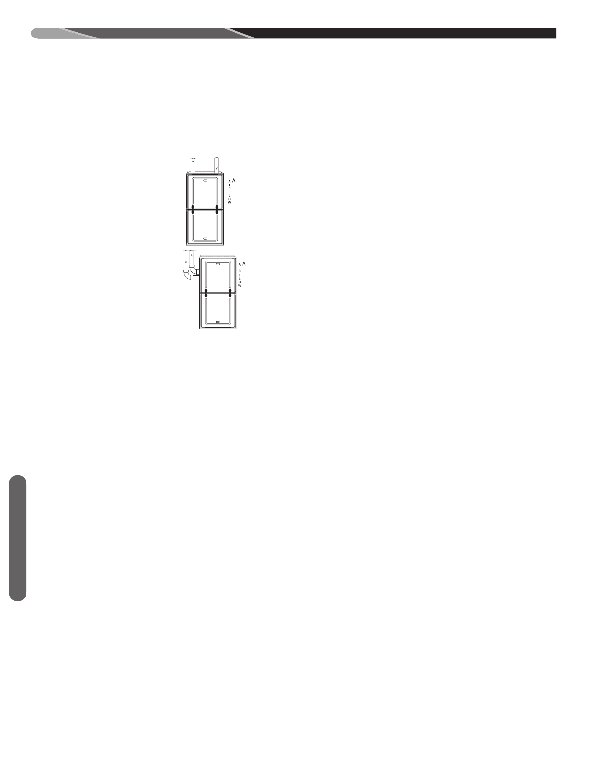
FIELD CONVERSIONS
AIRFLOW
AIRFLOW
AIRFLOW
AIRFLOW
FIELD CONVERSION TO VARIOUS CONFIGURATIONS
Furnaces can be converted to two different upflow configurations as follows. There are two different venting options, including a zero-clearance option, to give the installer flexibility in locating the venting for this furnace.
LISTS OF MATERIALS FOR PARTS BAGS AND CONVERSION KITS. . . . . . . . . . . . . . . . . . . . . . . . . . . . . . . . . . . . . . . . Pg 12
GENERAL CONVERSION INSTRUCTIONS AND TIPS . . . . . . . . . . . . . . . . . . . . . . . . . . . . . . . . . . . . . . . . . . . . . . . . . . Pg 13
UPFLOW WITH VERTICAL VENT. . . . . . . . . . . . . . . . . . . . . . . . . . . . . . . . . . . . . . . . . . . . . . . . . . . . . . . . . . . . . . . Pg 15-16
UPFLOW WITH LEFT SIDE VENT. . . . . . . . . . . . . . . . . . . . . . . . . . . . . . . . . . . . . . . . . . . . . . . . . . . . . . . . . . . . . . . Pg 17-18
(REQUIRES CONVERSION
KIT RXGY-CK)
DOWNFLOW WITH RIGHT VENT (NON-ZERO CLEARANCE). . . . . . . . . . . . . . . . . . . . . . . . . . . . . . . . . . . . . . . . . Pg 19-22
(REQUIRES CONVERSION
KIT RXGY-CK)
DOWNFLOW ZERO-CLEARANCE . . . . . . . . . . . . . . . . . . . . . . . . . . . . . . . . . . . . . . . . . . . . . . . . . . . . . . . . . . . . . . Pg 23-27
(REQUIRES CONVERSION
KIT RXGY-CK AND ZERO-
CLEARANCE KIT RXGY-ZK)
HORIZONTAL RIGHT WITH RIGHT VENT . . . . . . . . . . . . . . . . . . . . . . . . . . . . . . . . . . . . . . . . . . . . . . . . . . . . . . . . Pg 28-30
(REQUIRES CONVERSION
KIT RXGY-CK)
HORIZONTAL RIGHT WITH VERTICAL VENT . . . . . . . . . . . . . . . . . . . . . . . . . . . . . . . . . . . . . . . . . . . . . . . . . . . . . Pg 31-33
(REQUIRES CONVERSION
Field Conversions
KIT RXGY-CK)
HORIZONTAL LEFT WITH RIGHT VENT . . . . . . . . . . . . . . . . . . . . . . . . . . . . . . . . . . . . . . . . . . . . . . . . . . . . . . . . . . Pg 34-38
(REQUIRES CONVERSION
KIT RXGY-CK AND ZERO-
CLEARANCE KIT RXGY-ZK)
HORIZONTAL LEFT WITH LEFT VENT . . . . . . . . . . . . . . . . . . . . . . . . . . . . . . . . . . . . . . . . . . . . . . . . . . . . . . . . . . . Pg 39-41
14
(REQUIRES CONVERSION
KIT RXGY-CK)
AIRFLOW
AIRFLOW
AIRFLOW
AIRFLOW
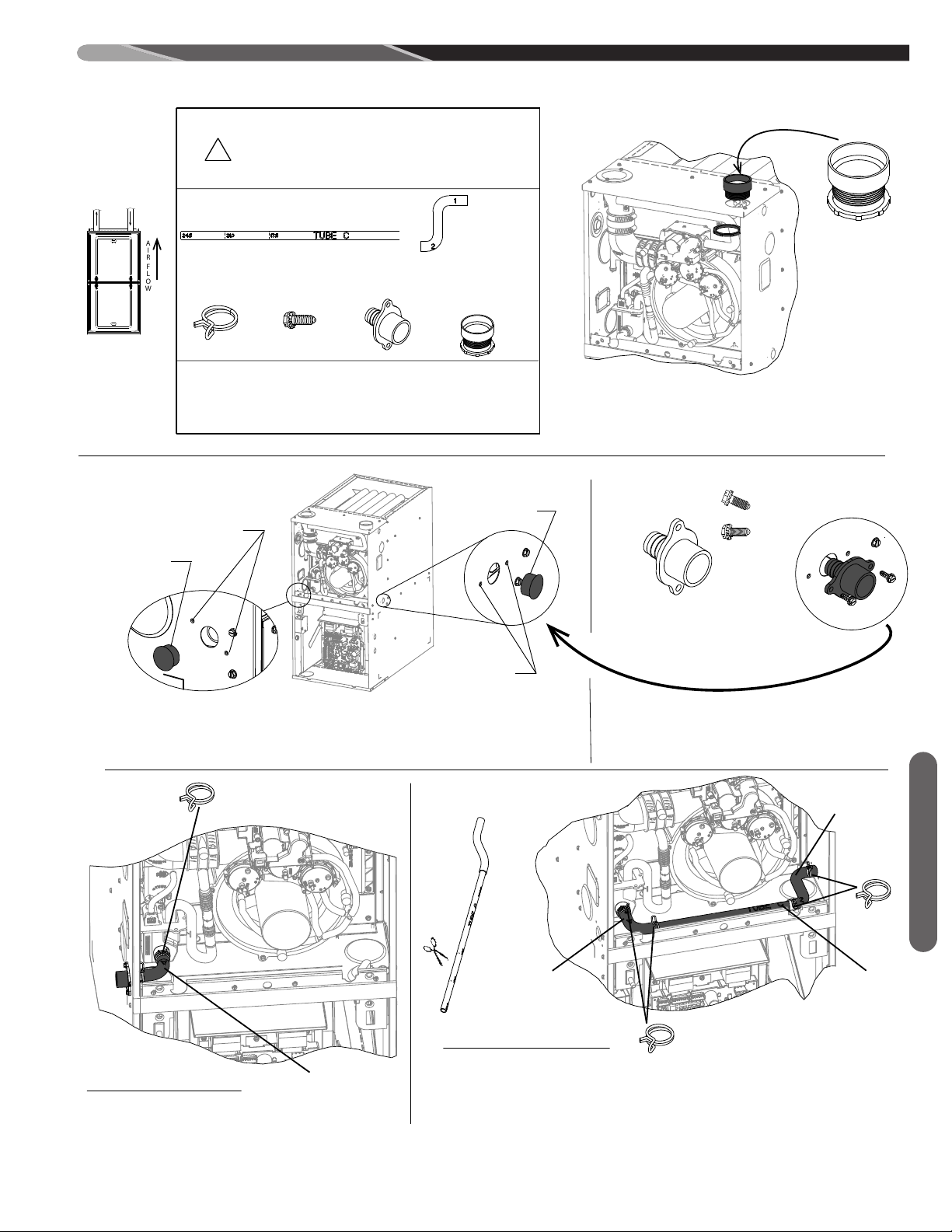
NOTE: THESE CONVERSION INSTRUCTIONS ARE INTENTIONALLY GENERIC, SOME PARTS MAY BE DIFFERENT IN YOUR FURNACE
ST-A1194-68-00
NOTE: PLIERS NECCESSARY TO ADD OR REMOVE CLAMPS
PARTS NEEDED:
PARTS NEEDED FOR THIS CONVERSION REQUIRE ITEMS
FROM THE PARTS BAG ONLY. NO OTHER CONVERSION
KITS ARE NEEDED.
!
TUBE C
B
ULKHEAD
COUPLING
FROM PARTS BAG (PROVIDED WITH UNIT)
(X2)
#8 X 1/2"
SCREW
H
OSE
CLAMP
INTAKE
COUPLING
W/ NUT
DRILL
1/8" DRILL BIT
PLIERS
1/4" HEX HEAD DRIVER
TUBING CUTTER
TOOLS/MATERIALS NEEDED:
(X3)
HOSE -
DOUBLE ELBOW
UPFLOW VERTICAL VENT
"
*
3
'
-
0
8
INSTALL INTAKE COUPLING IN TOP PLATE
1
INSTALL
DETERMINE RIGHT OR LEFT DRAIN OPTION.
LOCATE 7/8” HOLE IN JACKET SIDE.
REMOVE PLUG - DISCARD
DRILL (2) Ø 1/8” HOLES FOR THE BULKHEAD COUPLING.
2
3
OPTION DRAIN LEFT
DRILL 1/8”
7/8” PLUG
D
ISCARD
DRILL 1/8”
7/8” PLUG
DISCARD
INSTALL BULKHEAD COUPLING USING (2) SCREWS.
INSTALL IN JACKET WITH THE BARBED FITTING
POINTED INTO THE VESTIBULE.
INSTALL
OPTION DRAIN RIGHT
4a - LEFT SIDE DRAIN OPTION
ATTACH HOSE A (PRE-INSTALLED) TO BULKHEAD COUPLING.
INSTALL HOSE CLAMP ON HOSE OVER BULK HEAD COUPLING.
4b - RIGHT SIDE DRAIN OPTION
4b1 - CUT TUBE “C” TO FIT CORRESPONDING CABINET WIDTH.
4b2 - INSERT TUBE “C” INTO END “2” OF HOSE- DOUBLE ELBOW
4b3 - SLIDE TWO WIRE CLAMPS OVER TUBE “C”, SLIDE ONE WIRE CLAMP OVER
END “1” OF HOSE - DOUBLE ELBOW.
4b4 - INSTALL TUBE “C” WITH HOSE CLAMP AS SHOWN TO HOSE “A” “PRE ASSEMBLED”.
4b5 - ATTACH HOSE - DOUBLE ELBOW TO BULKHEAD COUPLING POSITION WIRE HOSE
CLAMP.
4A
4B
TUBE C
CUT TO FIT
CABINET WIDTH
2
HOSE A
TUBE C
HOSE-DOBLE
ELBOW
HOSE A
(X2)
Field Conversions
15

ST-A1194-68-00
Notes:
Checklist:
__ VERIFY ALL HOSES ARE SECURE AND FULLY SEATED.
__ CONFIRM THAT ALL HOSES ARE FREE OF KINKS.
_
_ CONFIRM ALL HOSES AND OTHER DRAIN PARTS HAVE A
SLOPE IN DIRECTION OF WATER FLOW
__ BOTH WORM DRIVES ON THE HOSE CLAMPS OF THE IDB COUPLING
MUST BE LOCATED ON THE TOP OF THE COUPLING. SEE LOCATION
DETAIL IN THE GENERAL CONVERSION INSTRUCTIONS AT THE
BEGINNING OF THIS SECTION.
__ ALL CLAMPS AND COUPLINGS ARE TIGHTENED
__ ALL DRAIN PORTS ARE PLUGGED
_
_ UNIT HAS FORWARD PITCH
__ HEAT TAPE INSTALLED (IF REQUIRED)
Field Conversions
16
DRILL
1/8" DRILL BIT
P
LIERS
FLAT HEAD SCREWDRIVER
5/16 HEX HEAD DRIVER
1/4" HEX HEAD DRIVER
TUBING CUTTER
TOOLS/MATERIALS NEEDED:
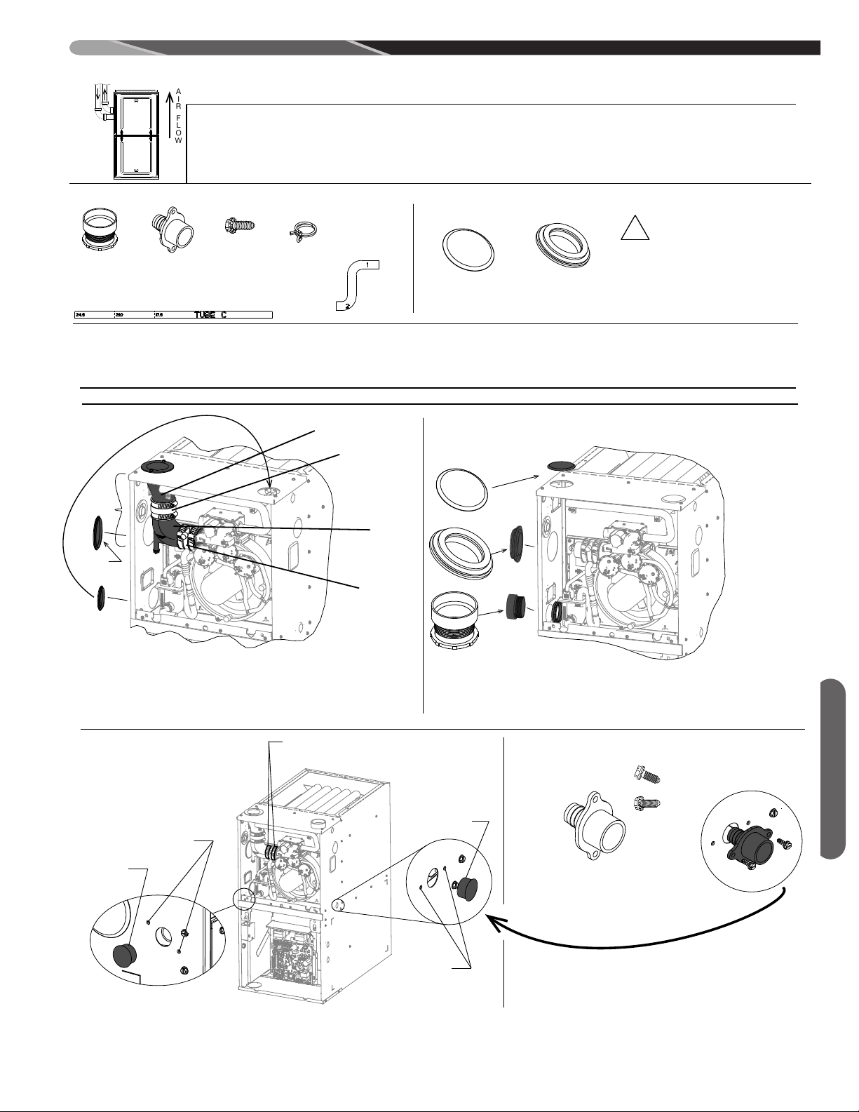
UPFLOW LEFT VENT
NOTE: THESE CONVERSION INSTRUCTIONS ARE INTENTIONALLY GENERIC, SOME PARTS MAY BE DIFFERENT IN YOUR FURNACE
ST-A1194-69-00
PARTS NEEDED:
(X2)
F
ROM PARTS BAG (PROVIDED W/UNIT)
I
NTAKE
COUPLING
W/ NUT
BULKHEAD
COUPLING
#
8 X 1/2"
SCREW
TUBE C
HOSE
CLAMP
F
ROM CONVERSION KIT RXGY-CK
2-3/8" PIPE
GROMMET
2-5/8" FLUSH
MOUNT PLUG
PARTS NEEDED FOR THIS
CONVERSION REQUIRE THE
O
UTLINED ITEMS FROM THE PARTS BAG
A
ND CONVERSION KIT RXGY-CK. YOU
M
UST HAVE THESE PARTS BEFORE
P
ROCEEDING.
!
Î
*
3
(X3)
H
OSE DOUBLE
ELBOW
1a - REMOVE FLUE TRANSITION, TRANSITION COUPLING, AND ELBOW.
(NOTE: REMOVE INDUCER COUPLING W/ELBOW FOR EASIER REMOVAL).
1b - REMOVE 3-3/8" FLUSH MOUNT PLUG FROM JACKET - DISCARD.
1c - RELOCATE 2-3/8" FLUSH MOUNT PLUG FROM JACKET TO TOP PLATE.
2
2a - INSTALL 2-5/8" FLUSH MOUNT PLUG IN TOP PLATE.
2b - INSTALL 2" PIPE GROMMET AS SHOWN.
2c - INSTALL INTAKE COUPLING AS SHOWN.
2b
2c
2
a
2
-5/8”
IF THE IDB
C
OUPLING IS
R
EMOVED, IT
MUST BE
REPLACED IN
THE PROPER
ORIENTATION.
AN ARROW IS
PRESENT ON
THE COUPLING
TO INDICATE
THE DIRECTION
OF EXHAUST
FLOW. MAKE
SURE THE
ARROW POINTS
IN THE
CORRECT
DIRECTION.
NOTE:
1
IDB COUPLING
(RETAIN)
FLUE TRANSITION
(DISCARD)
TRANSITION
C
OUPLING
(
DISCARD)
ELBOW
(DISCARD)
1a
1b
1c
R
E
-LOC
A
T
E
DISCARD
DETERMINE RIGHT OR LEFT DRAIN OPTION.
LOCATE 7/8” HOLE IN JACKET SIDE.
REMOVE PLUG - DISCARD
DRILL (2) Ø 1/8” HOLES FOR THE BULKHEAD COUPLING.
3
4
DRILL 1/8”
DISCARD
DRILL 1/8”
DISCARD
INSTALL BULKHEAD COUPLING USING (2) SCREWS.
INSTALL IN JACKET WITH THE BARBED FITTING
POINTED INTO THE VESTIBULE.
INSTALL
SEE CRITICAL HOSE CLAMP LOCATION NOTE
IN THE GENERAL CONVERSION INSTRUCTIONS.
Field Conversions
17
ST-A1194-69-00
Notes:
NOTE: PLIERS NECCESSARY TO ADD OR REMOVE CLAMPS
Checklist:
__ VERIFY ALL HOSES ARE SECURE AND FULLY SEATED.
__ CONFIRM THAT ALL HOSES ARE FREE OF KINKS.
__ CONFIRM ALL HOSES AND OTHER DRAIN PARTS HAVE A
SLOPE IN DIRECTION OF WATER FLOW
__ BOTH WORM DRIVES ON THE HOSE CLAMPS OF THE IDB COUPLING
MUST BE LOCATED ON THE TOP OF THE COUPLING. SEE LOCATION
DETAIL IN THE GENERAL CONVERSION INSTRUCTIONS AT THE
BEGINNING OF THIS SECTION.
__ ALL CLAMPS AND COUPLINGS ARE TIGHTENED
__ ALL DRAIN PORTS ARE PLUGGED
__ UNIT HAS FORWARD PITCH
__ HEAT TAPE INSTALLED (IF REQUIRED)
5a - LEFT SIDE DRAIN OPTION
ATTACH HOSE A (PRE-INSTALLED) TO BULKHEAD COUPLING.
I
NSTALL HOSE CLAMP ON HOSE OVER BULK HEAD COUPLING.
5
b - RIGHT SIDE DRAIN OPTION
5b1 - CUT TUBE “C” TO FIT CORRESPONDING CABINET WIDTH.
5b2 - INSERT TUBE “C” INTO END “2” OF HOSE- DOUBLE ELBOW
5
b3 - SLIDE TWO WIRE CLAMPS OVER TUBE “C”, SLIDE ONE WIRE CLAMP OVER
END “1” OF HOSE - DOUBLE ELBOW.
5
b4 - INSTALL TUBE “C” WITH HOSE CLAMP AS SHOWN TO HOSE “A” “PRE ASSEMBLED”.
5b5 - ATTACH HOSE - DOUBLE ELBOW TO BULKHEAD COUPLING POSITION WIRE HOSE
CLAMP.
5A
5B
H
OSE A
TUBE C
HOSE-DOBLE
ELBOW
TUBE C
CUT TO FIT
CABINET WIDTH
2
HOSE A
(
X2)
Field Conversions
18
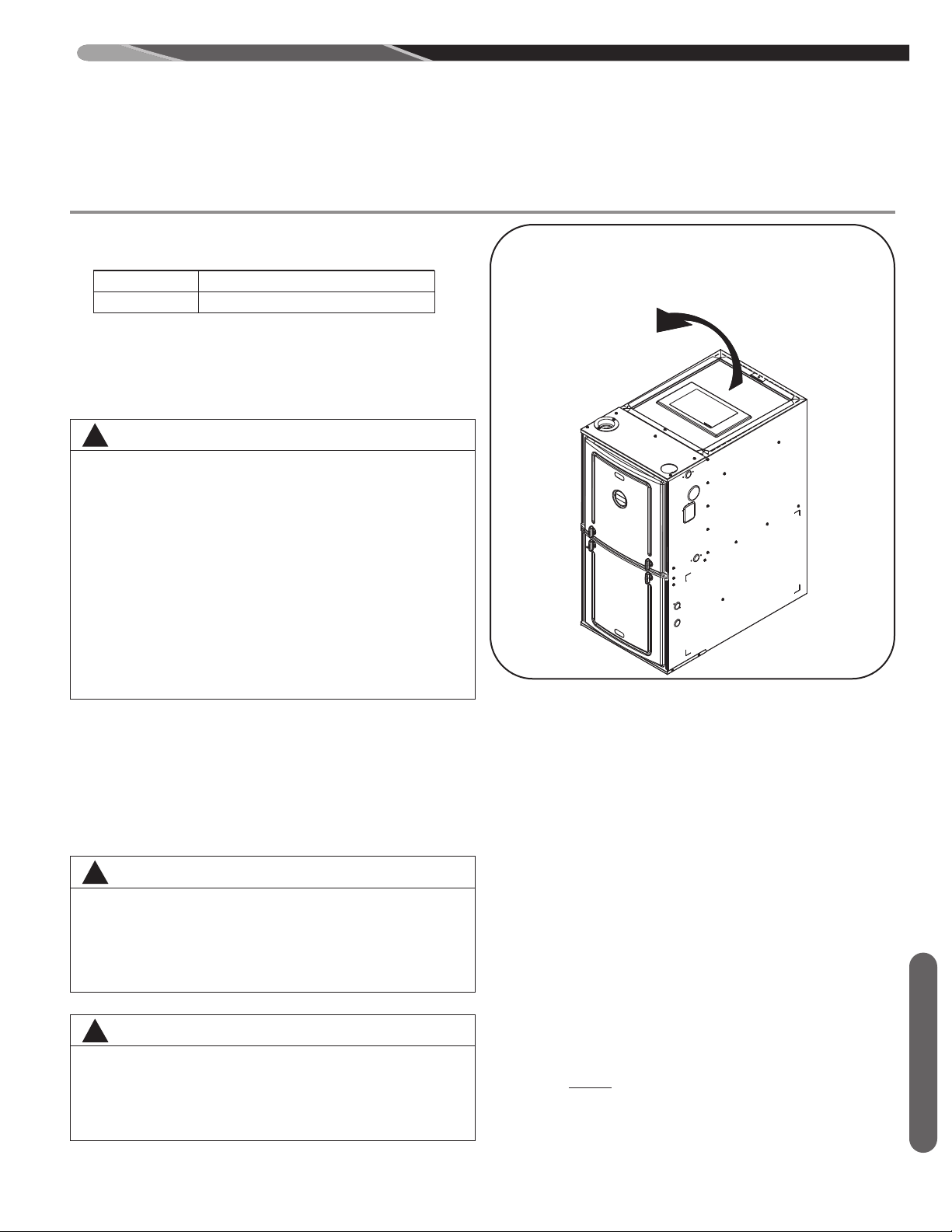
DUCTING
REMOVE SOLID
BASE FROM TOP
OF UNIT.
2
REMOVE SOLID BASE PANEL FROM THE
TOP BEFORE INSTALLING FURNACE
External filter racks are available from the distributor. Use
the following part numbers when ordering:
RXGF-CA External Side Filter Rack Kit
RXGF-CB External Bottom Filter Rack Kit
Proper air flow is required for the correct operation of this
furnace. Restricted air flow can cause erratic operation
and can damage the heat exchanger. The duct system
must carry the correct amount of air for heating and cooling if summer air conditioning is used.
WARNING
!
SOME HEATING AIRFLOW VALUES MAY BE
HIGHER THAN THOSE REQUIRED FOR COOLING.
BE SURE TO SIZE DUCT FOR THE MAXIMUM POSSIBLE AIRFLOW VALUE.
SIZE AIRFLOW DISTRIBUTION SYSTEM TO ACCEPTABLE INDUSTRY STANDARDS AND METHODS. TOTAL STATIC PRESSURE DROP OF THE AIR
DISTRIBUTION SYSTEM SHOULD NOT EXCEED 1.0
INCHES W.C. THIS WILL INCLUDE ANY AIR CONDITIONER COIL, AIR FILTRATION SYSTEM, ZONING
SYSTEM, DUCTWORK, ETC. REFER TO ADDED
EQUIPMENT TECHNICAL INFORMATION TO OBTAIN PRESSURE DROP INFORMATION WHEN
EQUIPMENT IS OPERATING AT RECOMMENDED
HEATING OR COOLING CFMS.
IMPORTANT: When using outside air, design and adjust
the system to maintain a return air temperature ABOVE
55° F during the heating season.
NOTE:Return air grilles and warm air registers must not
be obstructed or closed.
NOTE:Both flanges on the supply and return openings
must be bent either up or down but cannot remain flat as
shipped from the factory. See Figure 8 for details.
WARNING
!
THE SOLID METAL BASE PAN MUST BE REMOVED
FROM THE TOP OF THE FURNACE BEFORE INSTALLING THE FURNACE. FAILURE TO REMOVE
THIS PAN FROM THE SHIPPING POSITION CAN RESULT TO DAMAGE TO THE FURNACE OR EQUIPMENT.
WARNING
!
BLOWER AND BURNERS MUST NEVER BE OPERATED
WITHOUT THE BLOWER DOOR IN PLACE. THIS IS TO
PREVENT DRAWING GAS FUMES (WHICH COULD CONTAIN HAZARDOUS CARBON MONOXIDE) INTO THE
HOME THAT COULD RESULT IN PERSONAL INJURY OR
DEATH.
FIGURE 6
ST-A1194-49
UPFLOW INSTALLATIONS
1. Position the unit to minimize long runs of duct or runs
of duct with many turns and elbows.
2. For side return: Cut an opening in the side. The opening should be cut the full width and height of the
knockouts on the unit. See Figure 9.
3. If summer air conditioning is desired, position the indoor coil on the supply-air side of the unit. Ensure
that no air can bypass the coil.
4. Connect the furnace to the supply air plenum.
5. Connect the return air ducting to the return-air opening at the bottom and/or side of the unit. Make the
connections air-tight to prevent the migration of toxic
fumes and odors including carbon monoxide from migrating into the living space.
6. If a filter is installed near the furnace, be sure to have
adequate space for installation and removal of the
unit filter.
7. NOTE: Where the maximum airflow is 1800 CFM or
more, BOTH sides or the bottom must be used for the
return air.
NOTE: DO NOT take return air from furnace rooms,
garages or cold areas. Avoid return air from utility rooms,
kitchens, laundry rooms and bathrooms.
Ducting
19
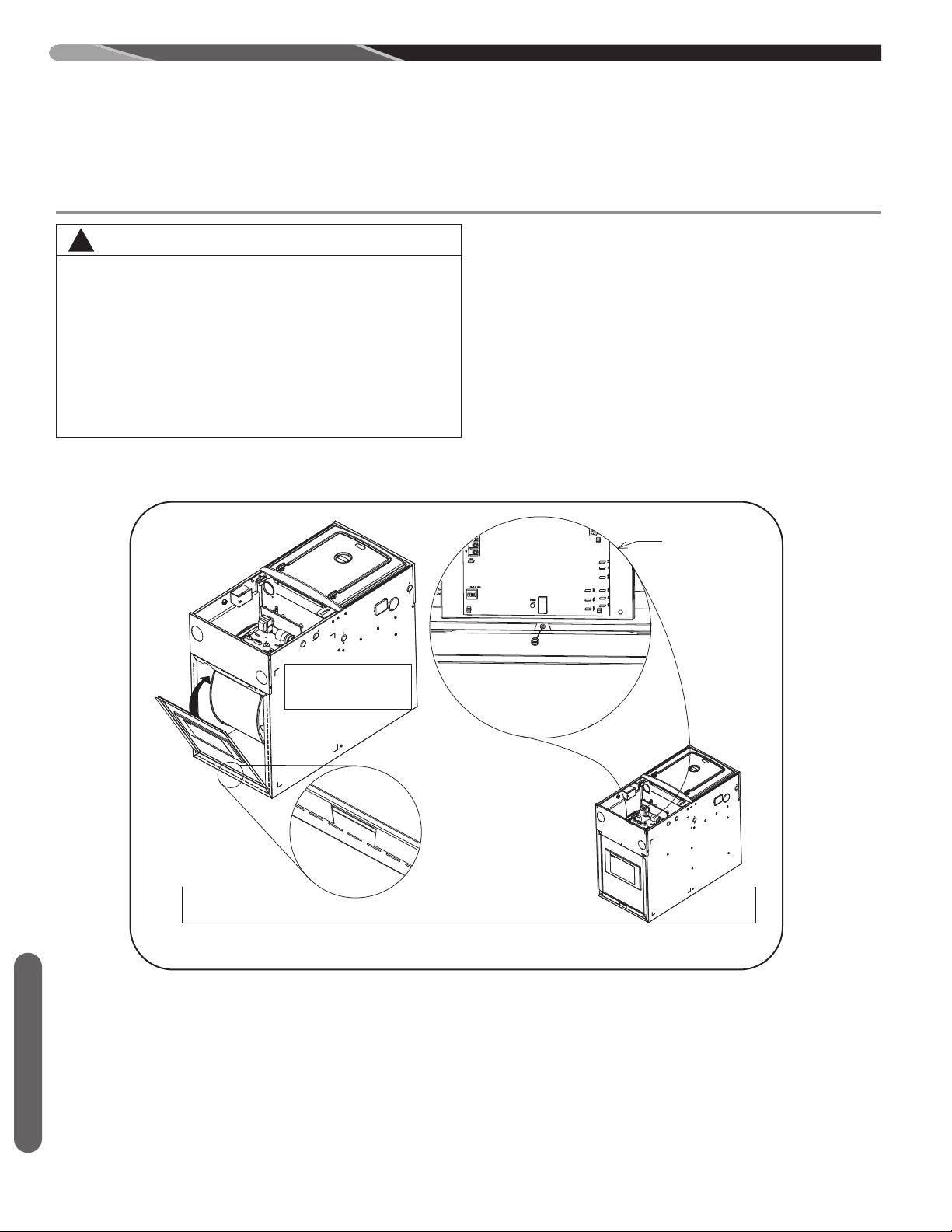
DUCTING
1 REMOVE BLOWER
DOOR AS SHOWN
RETAINING TAB
DETAIL
INSTALLATION OF SOLID METAL BASE FOR SIDE
RETURN APPLICATIONS
INTERNAL VIEW
OF BLOWER
COMPARTMENT
2 INSERT TAB ONTO
FLANGE AND PUSH
PANEL INTO PLACE
3 INSTALL SCREW IN TAB LOCATED
IN THE BLOWER COMPARTMENT
TAPE ALL EDGES OF BOTTOM
TO COVER GAPS
4 AFTER
INSTALLATION
OF BOTTOM
PLATE, SEAL ALL
SEAMS TIGHT
WITH METAL
TAPE
WARNING
!
UPFLOW FURNACE: THE SOLID METAL BASE
PLATE (SHIPPED WITH THE FURNACE) MUST BE
INSTALLED IN THE FURNACE BOTTOM WHEN
USING SIDE AIR RETURN. FAILURE TO INSTALL A
BASE PLATE COULD CAUSE THE PRODUCTS OF
COMBUSTION TO CIRCULATE INTO THE LIVING
SPACE AND CREATE POTENTIAL LY HAZARDOUS
CONDITIONS, INCLUDING CARBON MONOXIDE POISONING OR DEATH. FOR BOTTOM RETURN, A
SOLID METAL BASE PAN MUST NOT BE INSTALLED.
FIGURE 7
Ducting
20
ST-A1194-49
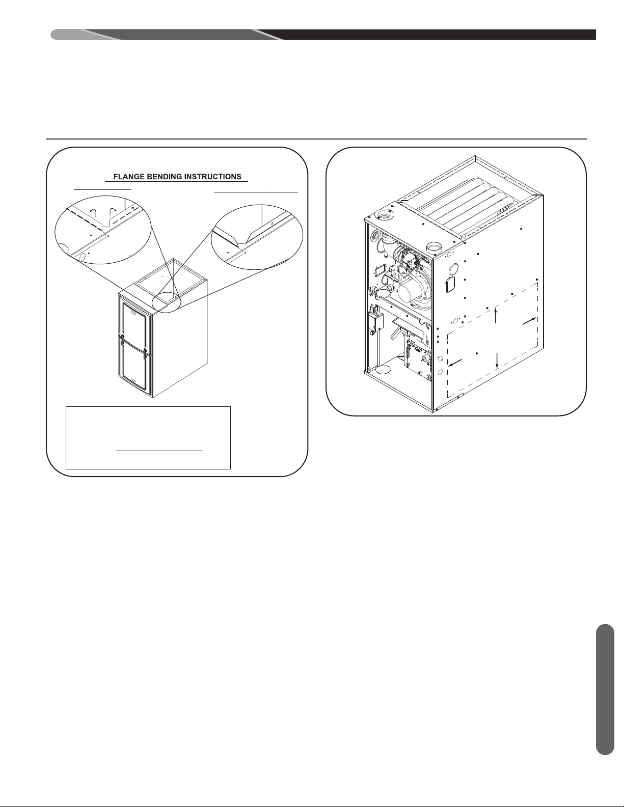
CUT - OUT USING
EMBOSSED ANGLES AS
A GUIDE FOR PROPER
SIZE 23” x 14”
DUCTING
INSTALLER BENT - UP
FIGURE 8
AS - SHIPPED FLAT
NOTES:
THIS VIEW IS REPRESENTATIVE OF BOTH SUPPLY AND RETURN OPENINGS.
DUCT FLANGES MUST BE FIELD-BENT ALONG PERFORATIONS
EITHER INTO OR OUT OF THE FURNACE AS NECESSARY FOR
INSTALLATIONS BUT NEITHER FLANGE CAN REMAIN FLAT.
INSTALLER SHOULD USE DUCK BILLED PLIERS (AKA FOLDING
PLIERS) TO BEND THE FLANGE ALONG THE PERFORATIONS.
ALTERNATE - BENT (DOWN)
FIGURE 9
INSTALLER BENT - UP
ST-A1194-04-X0
ST-A1194-39-00
Ducting
21
GENERAL VENTING REQUIREMENTS AND
GUIDELINES
VENTING & COMBUSTION AIR REQUIREMENTS
WARNING
!
READ AND FOLLOW ALL INSTRUCTIONS IN THIS
Venting
SECTION. FAILURE TO PROPERLY VENT THIS
FURNACE CAN CAUSE CARBON MONOXIDE POISONING, OR AN EXPLOSION OR FIRE, RESULTING IN PROPERTY DAMAGE, PERSONAL INJURY
OR DEATH.
WARNING
!
THIS FURNACE AND ANY OTHER FUEL-BURNING
APPLIANCE MUST BE PROVIDED WITH ENOUGH
FRESH AIR FOR PROPER COMBUSTION AND
VENTILATION OF THE FLUE GASES. MOST
BUILDINGS WILL REQUIRE THAT OUTSIDE AIR BE
SUPPLIED INTO THE FURNACE AREA. FAILURE
TO DO SO CAN CAUSE PERSONAL INJURY OR
DEATH FROM CARBON MONOXIDE POISONING.
REFER TO SECTION TITLED “NON-DIRECT VENT-
ING” TO DETERMINE IF THE FURNACE MUST USE
OUTSIDE AIR FOR COMBUSTION.
This furnace removes both sensible and latent heat from
the combustion gases. Removal of latent heat results in
the condensation of flue gas water vapor. This condensed
water vapor drains from the secondary heat exchanger
and out of the unit into the drain trap.
When installed as a non-direct vent furnace, only exhaust
piping is required and inside combustion air may be used.
Refer to the section on “NON-DIRECT VENTING.”
Direct vent installations require a dedicated combustion
air and venting system. All air for combustion is taken
from the outside atmosphere and all combustion products
are discharged to the outdoors.
Adequate facilities for providing air for combustion and
ventilation must be provided in accordance with Section
5.3, “Air for Combustion and Ventilation” of the National
Fuel Gas Code, ANSI Z223.1 (latest edition), in Canada
CSA B149.1; Canadian Natural Gas and Propane Installation Code and The National Fire Code of Canada, or
applicable provisions for the local building codes, and not
obstructed so as to prevent the flow of air to the furnace.
IMPORTANT: Air for combustion and ventilation must not
come from a corrosive atmosphere. Any failure due to
corrosive elements in the atmosphere is excluded from
the warranty coverage.
Combustion air must be free of acid-forming chemicals
such as sulfur, fluorine and chlorine. These elements are
found in aerosol sprays, detergents, bleaches, cleaning
solvents, air fresheners, paint and varnish removers, refrigerants and many other commercial and household
products. When burned in a gas flame, vapors from these
products form acid compounds. The acid compounds increase the dew point temperature of the flue products and
are highly corrosive after they condense.
The following types of installations (but not limited to the
following) may require outdoor air for combustion (direct
vent) due to chemical exposures:
If combustion air is exposed to the following substances
(but not limited to the following), it should not be used and
the furnace may require outdoor air for combustion (direct
vent).
!
ALL FURNACE INSTALLATIONS MUST COMPLY
WITH THE NATIONAL FUEL GAS CODE, IN
CANADA CSA B149.1; CANADIAN NATURAL GAS
AND PROPANE INSTALLATION CODE AND THE
NATIONAL FIRE CODE OF CANADA, NFPA 54 AND
LOCAL CODES TO PROVIDE ADEQUATE COMBUSTION AND VENTILATION AIR FOR THE FURNACE.
FAILURE TO DO SO CAN RESULT IN EXPLOSION,
FIRE, PROPERTY DAMAGE, CARBON MONOXIDE
POISONING, PERSONAL INJURY OR DEATH.
Combustion air requirements are determined by whether
the furnace is in an open (unconfined) area or in a confined space such as a closet or small room.
When the furnace is installed in the same space with
other gas appliances, such as a water heater, be sure
there is an adequate supply of combustion and ventilation
air for the furnace and the other appliances. Do not delete
or reduce the combustion air supply required by the other
gas appliances in this space. See Z223.1, National Fuel
Gas Code (NFPA 54), in Canada CSA B149.1; Canadian
Natural Gas and Propane Installation Code and The National Fire Code of Canada, for determining the combustion air requirements for gas appliances. An unconfined
space must have at least 50 cubic feet (volume) for each
1,000 BTUH of the total input of all appliances in the
space. If the open space containing the appliances is in a
building with tight construction (contemporary construction), outside air may still be required for the appliances to
burn and vent properly. Outside air openings should be
sized the same as for a confined space.
Commercial buildingsBuildings with indoor poolsFurnaces installed in laundry roomsFurnaces in hobby or craft roomsFurnaces installed near chemical storageareas
Permanent wave solutionsChlorinated waxes and cleanersChlorine-based swimming pool chemicalsWater softening chemicalsDe-icing salts or chemicalsCarbon tetrachlorideHalogen type refrigerantsPrinting inks, paint removers, varnishes etc.Cleaning solvents (such as perchloroethyl-ene)
Hydrochloric acidCements and gluesAntistatic fabric softeners for clothes dryersMasonry curing and acid washing materials-
WARNING
22
GENERAL VENTING REQUIREMENTS AND
GUIDELINES
VENTING & COMBUSTION AIR REQUIREMENTS (cont.)
MPORTANT: ONLY THE CURRENT VENT INSTRUC-
I
TIONS APPLY. All 90 Plus Gas Furnaces cannot be com-
mon-vented.
OVERTEMPERATURE SAFETY
SWITCHES
Furnaces are equipped with safety switches in the burner
compartment to protect against over-temperature conditions caused by inadequate combustion air supply. The
switches are located in the burner compartment. If a
switch is tripped it must be manually reset after clearing
the fault condition which caused it to open.
!
WARNING
DO NOT BYPASS, JUMPER, OR REMOVE ANY
SAFETY SWITCH FROM THE FURNACE CONTROL
CIRCUIT. IF A SAFETY SWITCH CAUSES THE FURNACE TO SHUT DOWN OR OPERATE INTERMITTENTLY, IT IS AN INDICATION OF A POTENTIAL
SAFETY HAZARD THAT MUST BE ADDRESSED BY
A QUALIFIED TECHNICIAN, SERVICE AGENCY OR
THE GAS SUPPLIER. DO NOT RESET SAFETY
CONTROLS WITHOUT CORRECTIVE ACTION
AND/OR VERIFICATION OF PROPER SAFE OPERATION BY A QUALIFIED INSTALLER, SERVICE
AGENCY OR THE GAS SUPPLIER.
REPLACE ANY SAFETY CONTROL COMPONENT
ONLY WITH IDENTICAL OEM REPLACEMENT
PARTS
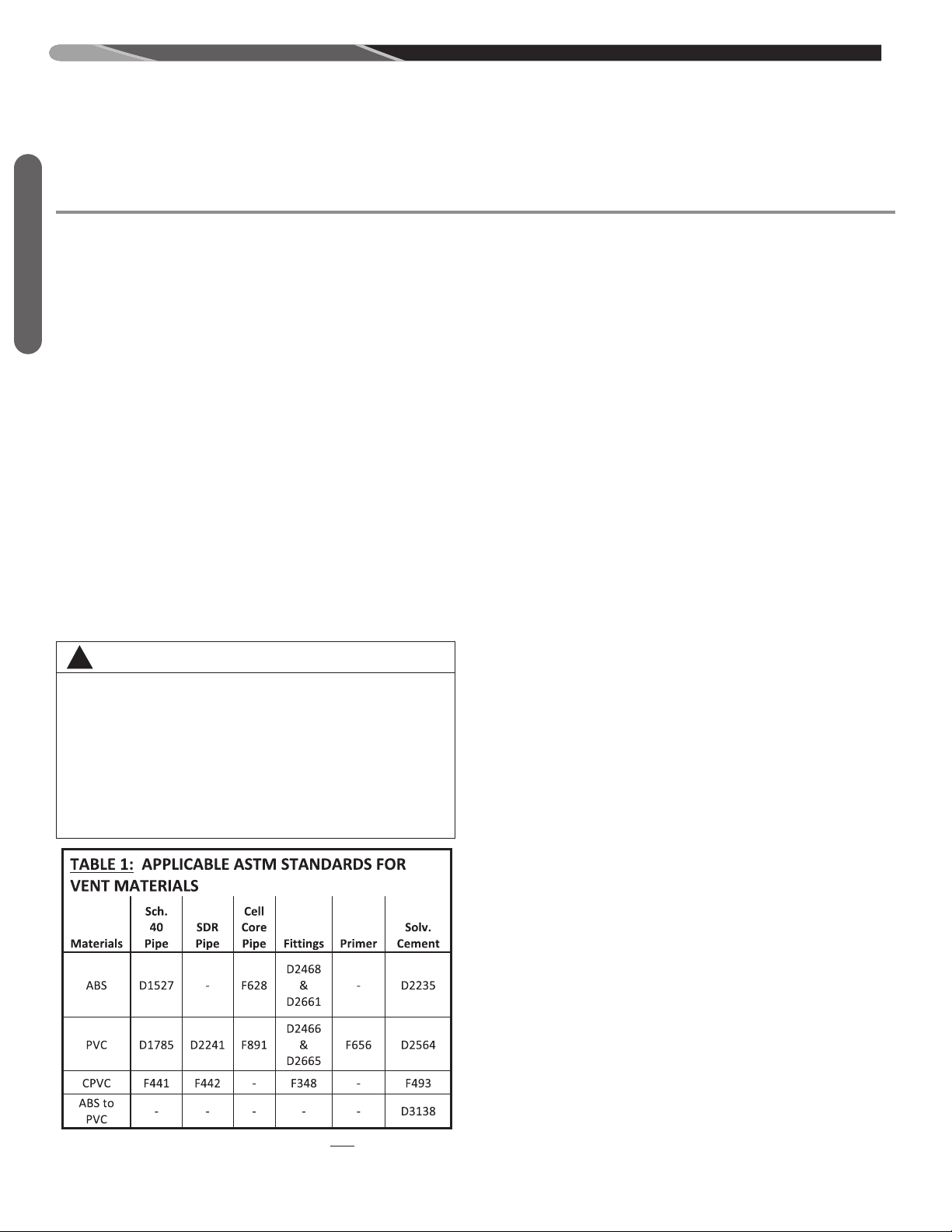
MATERIAL REQUIREMENTS
PIPING REQUIREMENTS
The combustion air and vent pipe fittings must conform to
American National Standards Institute (ANSI) and American Society for Testing Materials (ASTM) standards
D1785 (Schedule 40 PVC), D2665 (PVC-DWV), D2241
(SDR-21 & SDR26-26 PVC), D2661 (ABS-DWV) or F628
(Schedule 40 ABS-DWV). For Canada PVC, CPVC and
polypropylene venting can be used and must conform
with ULCS-636C requirements.
IMPORTANT: The plastic combustion air and venting
components are of Schedule 40 PVC. If using ABS piping, ensure that the solvent cement is compatible for joining PVC to ABS components or use a mechanical
connection that can withstand the vent temperatures and
is corrosion resistant.
NOTE: Schedule 40 ABS-DWV pipe and fittings may be
used as an alternate to PVC pipe for the combustion air
inlet and vent pipes.
NOTE: Cellular core PVC is also approved for use. It
must be Schedule 40PVC-DWV cellular pipe for nonpressure applications and manufactured under ASTM-F-
891.
All exhaust piping must be installed in compliance with
the chapter titled; “Venting of Appliances” in the latest
dition of the National Fuel Gas Code, NFPA-54/ANSI
e
Z223.1, CSA B149.1; Canadian Natural Gas and Propane
Installation Code (Canada), local codes or ordinances
and these instructions.
WARNING
!
IN CANADA, PRODUCTS CERTIFIED FOR INSTALLATION AND INTENDED TO BE VENTED WITH PLASTIC
VENT SYSTEMS (PVC, CVPC & POLYPROPYLENE)
MUST USE VENT SYSTEMS THAT ARE CERTIFIED
TO THE STANDARD FOR TYPE BH GAS VENTING
SYSTEMS, ULC S636.
THE COMPONENTS OF THE CERTIFIED MATERIAL
MUST NOT BE INTERCHANGED WITH OTHER VENT
SYSTEMS OR UNLISTED PIPE/FITTINGS.
PLASTIC COMPONENTS AND SPECIFIED PRIMERS
AND GLUES OF THE CERTIFIED SYSTEM MUST BE
FROM A SINGLE SYSTEM MANUFACTURER AND
NOT INTERMIXED WITH OTHER SYSTEM MANUFACTURER’S PARTS.
VENT TERMINATIONS ARE NOT REQUIRED TO BE
FROM THE SAME MANUFACTURER AS THE REST
OF THE VENTING BUT VENT TERMINATIONS MUST
BE ULC S636 APPROVED.
NOTE: WITH THE EXCEPTION OF THE TERMINATION
INLET AIR PIPING IS NOT CONSIDERED TO BE A
PART OF THE “VENTING SYSTEM”. THE REQUIREMENT THAT VENT MATERIAL BE CERTIFIED TO ULC
S636 DOES NOT APPLY TO INLET AIR PIPING.
REGARDLESS, ALL TERMINATIONS ON BOTH INLET
AND OUTLET PIPES MUST BE CONSTRUCTED
FROM COMPONENTS BUILT TO ULC-S636 REQUIREMENTS.
1. All horizontal piping must slope upward from the fur-
nace with a minimum slope of ¼ inch per foot of horizontal vent so that condensate drains back toward the
furnace.
2. All horizontal runs must be supported at least every 4
feet. No sags or dips are permitted.
3. IMPORTANT: Do not common vent with any other
appliance. Do not install in the same chase or chimney with a metal or high temperature plastic pipe from
another gas or fuel-burning appliance unless the required minimum clearances to combustibles are maintained between the plastic pipe and other pipes. For
Canada PVC, CPVC and polypropylene can be used
as long as they conform with ULCS-636C requirements.
4. All vent installed through unconditioned spaces where
below-freezing temperatures are expected must be insulated with an approved insulating material. Materials such as Armaflex or Rubatex insulation may also
be used as long as there is no heat tape applied to
the vent pipe. For horizontal runs where water may
collect, wrap the vent pipe with self-regulating 3 watt
or 6 watt heat tape. The heat tape must be U.L. listed
Venting
23
GENERAL VENTING REQUIREMENTS AND
GUIDELINES
VENTING & COMBUSTION AIR REQUIREMENTS (cont.)
and installed per the manufacturer’s instructions.
NOTE: Never cover heat tape with insulation.
5. The minimum vent pipe length is 5 feet [1.5m].
Venting
6. IMPORTANT: No part of the combustion air and/or
vent pipes may be installed underground.
7. Piping at a roof, wall or other penetration must be immobilized to prevent pipes from disconnecting. Disconnected pipes may allow flue products to be
released inside the structure.
8. For Direct Vent systems, all pipe penetrations through
roof or sidewall must be installed so that the vent and
combustion air intake pipes terminate in the same atmospheric pressure zone.
9. Vent terminations must be installed with the minimum
clearances specified in the TERMINATION REQUIREMENTS sections of this manual and Figure 15 (for
Non-Direct Vent) and Figures 16, 17 & 26 (for direct
Vent installations).
10. Piping external to the structure (excluding approved
venting terminations) and vent passing through unheated crawl-spaces, attics, verandas, patios or decks
must be insulated with approved insulating material to
prevent freezing as required for local climate.
JOINING PIPE AND FITTINGS
WARNING
!
PVC/CPVC SOLVENT CEMENTS AND PRIMERS
ARE HIGHLY FLAMMABLE. PROVIDE ADEQUATE
VENTILATION AND DO NOT ASSEMBLE NEAR A
HEAT SOURCE OR AN OPEN FLAME. DO NOT
SMOKE. AVOID SKIN OR EYE CONTACT. OBSERVE ALL CAUTIONS AND WARNINGS PRINTED
ON MATERIAL CONTAINERS. FAILURE TO FOLLOW THESE GUIDELINES MAY RESULT IN FIRE,
EXPLOSION OR ASPHYXIATION CAUSING PERSONAL INJURY OR DEATH.
(U.S. Only)
All pipe, fittings, solvent cement, primers and procedures
must be installed following the vent manufacturer’s installation instructions and must conform to American National
Standards Institute and American Society for Testing Materials (ANSI/ASTM) standards as shown in the Table 1
below:
CEMENTING JOINTS
Properly seal all joints in the PVC vent using the following
materials and procedures.
PVC CLEANER-PRIMER AND PVC
MEDIUM-BODY SOLVENT CEMENT
IMPORTANT: After cutting pipe, remove all ragged
edges and burrs. This is important to prevent reduction in
pressure drop throughout the system.
1. Cut pipe end square. Chamfer edge of pipe. Clean
fitting socket and pipe joint area of all dirt, grease and
moisture.
2. After checking pipe and socket for proper fit, wipe
socket and pipe with cleaner-primer. Apply a liberal
coat of primer to inside surface of socket and outside
of pipe. Read instructions included with the primer for
proper application.
3. Apply a thin coat of cement evenly within the socket.
Quickly apply a heavy coat of cement to the pipe end
and insert pipe into the fitting with a slight twisting
movement until it bottoms out.
NOTE: Cement must be fluid. If not, re-coat.
4. Hold the pipe in the fitting for 30 seconds to prevent
the tapered socket from pushing the pipe out of the fitting.
5. Wipe all excess cement from the joint with a rag.
Allow 15 minutes before handling. Cure time varies
according to fit, temperature and humidity.
NOTE: Stir the solvent cement frequently while using.
Use a natural bristle brush or the dauber supplied with the
can. The proper brush size is one inch.
IMPORTANT: For proper installation:
DO NOT use solvent cement that has become cur-
dled, lumpy or thickened.
DO NOT thin. Observe shelf precautions printed on
containers. For applications below 32°F, use only lowtemperature type solvent cement.
For Canadian installations all exhaust venting materials must be certified to
ULCS-636C.
24
GENERAL VENTING REQUIREMENTS AND
GUIDELINES
VENT PIPE SIZING AND MAXIMUM VENT LENGTHS
E
T
i
s
l
p
t
u
l
v
T
u
t
(
S
t
A
h
e
h
T
w
o
m
l
Q
e
h
p
n
c
u
n
e
e
r
e
h
e
s
n
e
n
e
e
h
e
s
e
h
4
/
1
p
g
n
i
o
l
s
a
h
t
i
s
a
i
h
h
t
u
u
n
e
V
I
U
c
n
o
c
g
n
i
p
i
s
a
h
f
o
h
t
g
e
r
u
s
s
v
i
u
q
e
o
t
p
u
f
o
h
t
g
g
n
e
l
t
r
a
e
r
h
w
d
d
n
a
t
s
n
r
u
t
a
c
i
f
i
c
e
t
a
P
s
FIGURE 10
ELBOWS
w
s
-
g
n
e
n
a
i
2
r
e
e
n
a
u
q
e
s
t
i
e
r
e
o
e
d
i
s
n
o
i
t
a
l
o
s
h
t
g
E
L
A
e
f
o
t
p
e
m
e
t
s
y
s
.
s
w
o
b
l
e
g
i
a
r
t
s
a
n
i
p
o
r
d
e
l
t
n
e
l
a
a
m
e
h
t
h
g
i
a
r
t
s
o
n
s
i
h
t
r
e
v
e
s
e
s
n
o
c
n
e
m
i
d
d
r
a
w
o
b
l
e
)
r
o
f
n
o
i
t
.
s
n
r
e
t
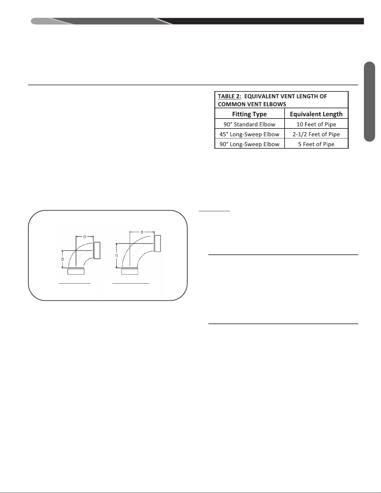
STANDARD 90°
2” D = 2 5/16”
3” D = 3 1/16”
A
(
p
e
e
e
l
a
v
i
u
q
3
r
o
h
c
n
e
l
a
v
i
u
q
t
n
e
l
a
v
i
b
t
h
g
i
m
t
s
e
h
t
f
o
n
s
f
o
s
e
r
e
f
f
i
d
f
s
n
n
l
N
s
n
t
t
a
t
K
e
e
r
w
S
Venting
H
T
G
N
E
L
T
N
E
V
T
d
e
s
u
y
l
t
n
e
u
q
e
r
f
s
i
s
h
t
g
n
e
l
t
n
e
v
t
n
e
l
a
v
i
u
q
,
s
g
n
i
t
t
i
f
f
o
p
o
r
d
e
r
u
s
s
e
r
p
r
o
f
t
n
u
o
c
c
a
o
t
e
h
t
s
i
g
n
i
t
t
i
f
a
f
o
h
t
g
n
e
l
t
n
e
l
a
v
i
u
q
e
e
h
T
t
n
e
l
a
v
i
u
q
e
n
a
s
a
h
t
a
h
t
e
p
i
p
f
o
n
o
i
t
c
e
s
t
h
h
t
i
W
.
d
e
s
u
g
n
i
t
t
i
f
e
h
t
s
a
n
o
i
t
a
c
i
l
p
p
a
e
h
t
n
a
c
m
e
t
s
y
s
t
n
e
v
a
,
t
p
e
c
n
o
c
t
n
e
v
h
t
g
t
n
e
v
d
n
a
s
w
o
b
l
e
f
o
r
e
b
m
u
n
m
u
m
i
x
t
n
e
l
a
v
i
u
q
e
m
u
m
i
x
a
m
e
h
t
s
a
g
n
o
l
s
a
e
p
i
p
.
d
e
d
e
e
c
x
e
s
h
t
g
n
e
l
t
n
e
v
m
u
m
i
x
a
m
t
n
e
l
a
v
i
u
q
e
e
h
t
s
e
i
f
i
c
e
p
s
3
e
l
b
a
e
b
n
a
c
t
a
h
t
s
w
o
b
l
e
f
o
s
e
p
y
t
t
n
e
r
e
f
f
i
d
l
w
o
h
s
0
1
e
r
u
g
i
F
.
m
e
t
s
y
s
t
n
e
v
a
g
n
i
t
c
u
r
9
p
e
e
w
s
-
g
n
o
l
d
n
a
d
r
a
d
n
a
t
s
r
o
f
s
n
o
i
s
n
e
d
r
a
d
n
a
t
S
,
1
1
3
3
M
T
S
A
y
b
d
e
i
f
i
c
e
p
s
s
a
F
c
i
t
s
a
l
P
)
V
W
D
(
t
n
e
V
d
n
a
e
t
s
a
W
,
n
i
a
r
D
LONG SWEEP 90°
2” D = 3 1/4”
3” D = 4 1/16”
w
o
b
l
e
)
n
r
u
t
4
/
1
(
°
0
9
)
s
u
i
d
a
R
-
g
n
o
L
A
o
f
e
p
i
p
t
h
g
i
a
r
t
s
f
o
t
e
e
f
5
f
o
h
t
g
n
e
l
t
n
e
v
t
w
o
b
l
e
°
0
9
d
r
a
d
n
a
t
s
A
.
e
p
i
p
c
i
t
s
a
l
p
h
c
n
i
.
e
p
i
p
t
h
g
i
a
r
t
s
f
o
t
e
e
f
0
1
f
o
h
t
g
n
e
l
t
n
e
v
t
s
e
c
n
a
t
s
m
u
c
r
i
c
n
i
d
e
s
u
e
b
n
a
c
h
t
g
n
e
h
t
t
a
t
n
e
v
e
h
t
n
e
h
t
g
n
e
l
o
t
y
r
a
s
s
e
c
e
n
u
c
c
a
e
g
r
a
l
h
t
i
w
s
a
e
r
a
n
i
s
a
h
c
u
s
,
e
r
u
t
c
u
e
l
a
v
i
u
q
e
e
h
t
s
w
o
h
s
2
e
l
b
a
T
.
r
e
t
n
i
w
n
i
.
s
w
o
b
l
e
f
o
s
e
p
y
t
t
n
T
d
e
t
s
i
L
.
e
c
a
n
r
u
f
h
c
a
e
r
o
f
r
e
r
u
t
c
a
f
u
n
a
m
e
h
t
y
b
d
e
i
f
i
c
e
p
s
s
0
n
a
t
°
D
b
-
t
i
p
E
1
S
6
2
r
T
o
f
t
a
m
e
l
b
a
d
n
e
p
e
t
d
n
o
y
e
e
r
u
s
s
e
r
e
l
p
m
a
x
K
0
6
A
.
t
n
e
v
p
h
c
n
i
e
f
1
3
=
y
t
Q
l
a
t
o
T
e
h
t
e
c
n
i
U
T
B
K
0
e
h
t
f
I
.
d
n
a
t
s
u
c
l
a
c
e
f
1
3
=
y
t
Q
l
a
t
o
T
a
t
s
n
i
s
i
h
x
a
m
t
o
s
m
u
m
i
x
n
i
n
o
t
n
e
l
b
a
t
e
h
h
c
t
i
w
s
:
s
d
U
T
B
h
t
i
w
n
u
r
.
e
p
i
i
2
f
o
t
e
°
0
9
,
5
=
m
i
x
a
m
e
c
a
n
r
u
f
a
l
l
a
t
s
n
i
b
l
e
d
r
a
w
n
o
i
t
a
l
i
2
f
o
t
e
°
0
9
,
5
=
n
o
i
t
a
l
l
s
m
u
m
i
b
e
v
a
h
a
u
d
i
v
i
d
m
o
c
e
r
i
t
a
r
e
p
o
e
v
-
t
c
e
r
i
,
5
=
y
t
q
p
i
p
h
c
n
w
s
-
g
n
o
l
q
e
m
u
f
5
6
s
i
o
r
f
n
o
i
t
s
n
i
s
w
o
e
b
d
l
u
o
p
i
p
h
c
n
a
d
n
a
t
s
T
O
N
s
i
d
e
i
f
i
c
e
p
u
q
n
e
e
l
a
t
s
n
i
l
a
d
n
e
m
.
n
o
a
t
s
n
i
t
n
n
o
l
°
0
9
=
e
l
e
p
e
e
n
e
l
a
v
i
u
i
h
t
,
t
e
e
m
a
x
E
m
o
d
a
e
t
l
o
f
s
a
=
e
o
b
l
e
d
r
p
e
c
c
a
i
h
t
r
o
f
d
e
i
f
i
l
a
s
n
o
i
t
a
l
m
s
n
o
i
t
n
o
i
t
a
l
l
e
w
s
-
g
=
s
w
o
b
l
t
n
e
v
t
l
a
t
s
n
i
s
1
e
l
p
s
-
g
n
o
l
f
:
s
w
o
l
=
s
w
s
a
e
l
b
a
t
e
d
o
m
s
e
h
t
y
b
c
i
f
i
c
e
p
u
a
c
y
a
s
d
e
e
n
o
b
l
e
p
e
e
1
3
e
5
2
e
6
5
s
h
t
g
n
e
i
n
o
i
t
a
l
n
i
e
r
e
w
e
p
e
e
w
e
1
3
e
0
5
e
1
8
c
x
e
t
i
.
l
a
f
u
n
a
m
a
t
s
n
i
,
s
a
r
r
e
e
s
o
f
1
3
a
d
n
a
s
w
e
l
a
v
i
u
q
e
l
a
v
i
u
q
e
l
a
v
i
u
q
e
i
f
i
c
e
p
p
e
c
c
a
s
d
e
l
l
a
t
s
,
s
w
o
b
l
e
l
a
v
i
u
q
e
l
a
v
i
u
q
e
l
a
v
i
u
q
h
t
s
d
e
e
.
r
e
r
u
t
c
s
n
o
i
t
a
l
l
c
i
t
g
n
o
l
t
o
2
t
e
e
f
t
n
t
e
e
f
t
n
t
e
e
f
t
n
a
r
o
f
d
.
e
l
b
a
t
h
t
i
w
e
h
t
t
e
e
f
t
n
t
e
e
f
t
n
t
e
e
f
t
n
5
6
e
25
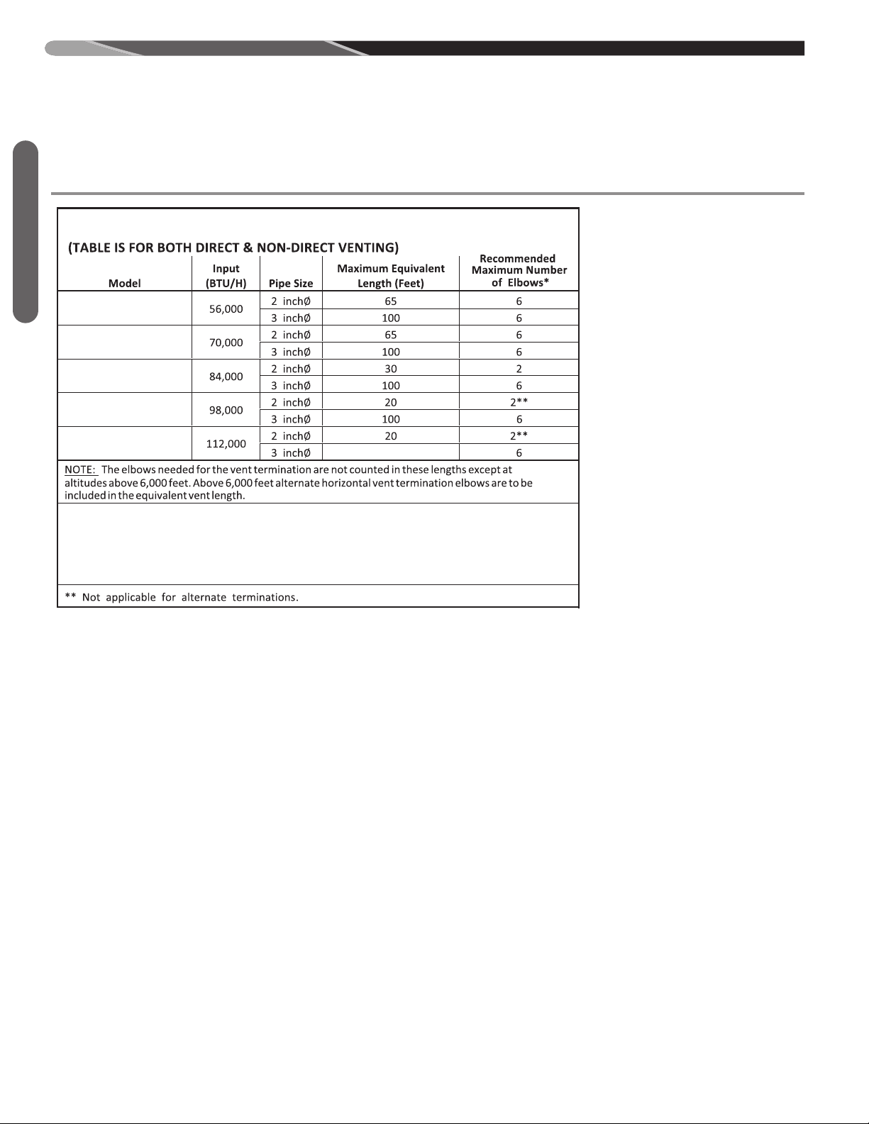
GENERAL VENTING REQUIREMENTS AND
(-)97V(-)060M317USA
(
-)97V(-)070M317USA
(-)97V(-)085M521USA
(-)97V(-)100M521USA
(-)97V(-)115M524USA
100
TABLE 3: MAXIMUM EQUIVALENT VENT LENGTH
GUIDELINES
VENT PIPE SIZING AND MAXIMUM VENT LENGTHS (cont.)
Venting
* This is the recommended maximum number of long sweep elbows for either 2 or 3 inch pipe. Combinaons
of long sweep 90s, standard 90s, or 45s may be used, but the manufacturer recommends the use of long
sweep 90s whenever possible because the use of the maximum number of standard 90 and 45 elbows
only may result in nuisance furnace outages due to individual installaon specifics.
Exceeding the recommended maximum number of elbows may cause nuisance operaon of the pressure switch.
For modulating furnaces, non-direct venting is only authorized for
vertical terminations.
26
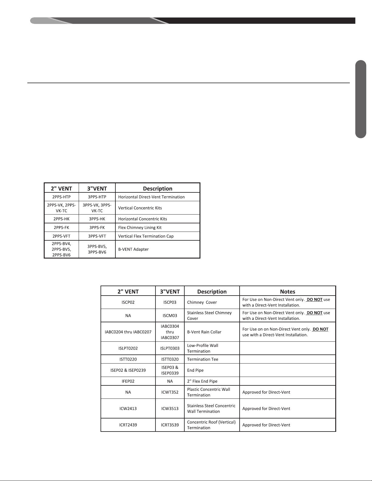
GENERAL VENTING REQUIREMENTS AND
GUIDELINES
VENT PIPE SIZING AND MAXIMUM VENT LENGTHS (cont.)
POLYPROPYLENE VENT PRODUCTS
Centrotherm brand Innoflue and Duravent Polypro Singlewall and flex venting products are approved for use on this
furnace product only in single appliance applications. Do
not exceed maximum venting lengths, diameters or elbows listed in these instructions (Vent Pipe Sizing and
Maximum Vent Lengths section [Table 3]). Application of
these products is limited to the terminations listed in Ta-
TABLE 4: DURAVENT BRAND POLYPRO & POLYPRO FLEX
TERMINATION COMPONENTS
bles 4 and 5 below. These manufacturers have provisions
for B-vent liners and chimney liners which can be used
with this furnace with non-direct venting applications only.
Refer to the manufacturer’s installation instructions for
proper installation. Contact the manufacturer for all installation and application information.
NOTE: These venting products are listed for use in
Canada under ULC-S636.
Venting
TABLE 5: CENTROTHERM BRAND ECO SYSTEMS TERMINATION COMPONENTS
27
GENERAL VENTING REQUIREMENTS AND
GUIDELINES
TERMINATION REQUIREMENTS
CAUTION
!
THE COMBUSTION PRODUCTS AND MOISTURE
Venting
IN THE FLUE GASES WILL CONDENSE AS THEY
LEAVE THE TERMINATION. THE CONDENSATE
CAN FREEZE ON THE EXTERIOR WALL, UNDER
THE EAVES AND ON SURROUNDING OBJECTS.
SOME DISCOLORATION TO THE EXTERIOR OF
THE BUILDING IS TO BE EXPECTED. HOWEVER,
IMPROPER LOCATION OR INSTALLATION CAN
RESULT IN FINISH DAMAGE TO THE BUILDING
AND MAY RE-CIRCULATE THE PRODUCTS OF
COMBUSTION INTO THE COMBUSTION AIR TERMINAL AND FREEZE.
Vent terminations for both Non-Direct and Direct-Vent installations must adhere to guidelines specified by the latest edition of ANSI Z21.47 Gas-Fired Central Furnaces.
These are clearly detailed in Figure 26 for Direct-Vent installations. In addition to these requirements, the installation and venting must also comply with the National Fuel
Gas Code (U.S.) and CSA-B149.1; Canadian Natural Gas
and Propane Installation Code (Canada) and the following
requirements must also be met:
NOTE: Screens of any kind on the inlet or exhaust pipes
are not permitted and will void the manufacturer’s warranty.
In addition to the requirements shown in Figure 26 for Direct-Venting, the vent must be installed with the following
minimum clearances:
1. The vent terminal shall have a minimum horizontal
clearance of 4 feet from electric meters, gas meters,
regulators and relief equipment.
2. Locate the furnace combustion air inlet a minimum of 3
feet from the vent of any other gas or fuel-burning ap-
pliance or clothes dryer to prevent recirculation of the
flue gases into the furnace combustion air inlet. The
only exception to this requirement is the case of multiventing two or more furnaces, which is covered in the
section on multiventing of these instructions.
In addition to the minimum clearances listed above and in
Figure 26 (Direct-Vent), the vent location should also be
governed by the following guidelines.
1. Avoid terminating under any kind of patio or deck.
However, if necessary, vent piping may be installed
under a deck as long as the termination(s) is (are) not
under the deck.
2. If installing the vent under a deck, insulate it to insure
that no condensate freezes and blocks the pipes.
3. Do not terminate in any area or behind any obstruction
that may allow the flue products to become stagnant
and/or re-circulate.
4. Do not locate on the side of a building with prevailing
winter winds. This will help prevent moisture from
freezing on the walls and overhangs (under eaves).
5. If extending vent through a brick or masonry surface, a
sleeve between the wall and venting is suggested to
protect against damage from thermal expansion and
contraction.
6. A corrosion-resistant sheet metal or plastic backing
plate installed on the wall behind the vent is suggested
to prevent exhaust gases and condensate from contacting the wall.
7. Avoid locating too close to shrubs as condensate may
stunt growth or kill them.
28
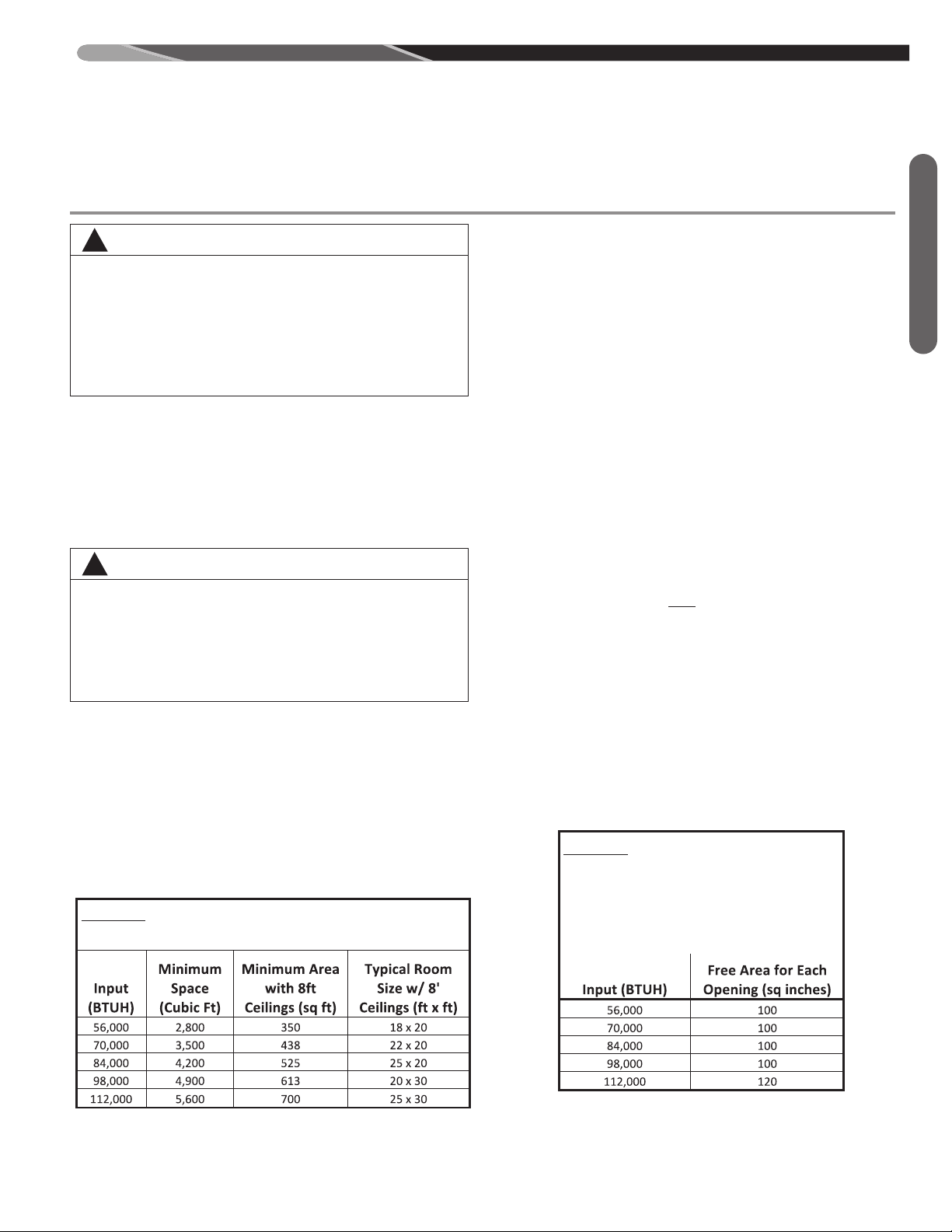
GENERAL VENTING REQUIREMENTS AND
GUIDELINES
NON-DIRECT VENT (VERTICAL TERMINATIONS ONLY)
WARNING
!
ALL FURNACE INSTALLATIONS MUST COMPLY WITH
THE NATIONAL FUEL GAS CODE, NFPA 54, AND IN
CANADA CSA B149.1; CANADIAN NATURAL GAS AND
PROPANE INSTALLATION CODE, THE NATIONAL FIRE
CODE OF CANADA, AND LOCAL CODES TO PROVIDE
ADEQUATE COMBUSTION AND VENTILATION AIR FOR
THE FURNACE. FAILURE TO DO SO CAN RESULT IN
EXPLOSION, FIRE, PROPERTY DAMAGE, CARBON
MONOXIDE POISONING, PERSONAL INJURY OR DEATH.
For improved indoor air quality, added safety and product performance we recommend direct vent type installations. If non-direct type vent system is used, the requirements for combustion
air must be provided as identified in the National Fuel Gas Code
and, in Canada, CSA B149.1; Canadian Natural Gas and
Propane Installation Code.
Combustion air requirements are determined by whether the furnace is in an open (unconfined) area or in a confined space
such as a closet or small room.
WARNING
!
READ AND FOLLOW THE GENERAL VENTING REQUIREMENTS AND GUIDELINES OF THIS MANUAL FOR ADDI-
TIONAL VENTING REQUIREMENTS PERTAINING TO ALL
FURNACE INSTALLATIONS (INCLUDING DIRECT AND
NON-DIRECT VENTING). FAILURE TO FOLLOW ALL INSTRUCTIONS IN THIS MANUAL CAN RESULT IN EQUIPMENT FAILURE, EQUIPMENT DAMAGE, PROPERTY
DAMAGE, PERSONAL INJURY OR DEATH.
CONFINED AND UNCONFINED SPACES
The below instructions are for U.S. installations only. The terms
Confined Space and Unconfined Space refer to U.S. installations only. In Canada the proper term to use is Enclosure when
specifying that a furnace is installed in a partially enclosed or
fully enclosed room or space. For Canadian installations, to determine combustion air requirements for non-direct vent installations, the installer must follow CSA B149.1; Canadian Natural
Gas and Propane Installation Code and NOT the below instructions.
TABLE 6: MINIMUM SPACE REQUIREMENTS
FOR UNCONFINED SPACE, NON-DIRECT VENT
FURNACE LOCATED IN AN UNCONFINED SPACE (U.S. INSTALLATIONS)
USING INDOOR AIR FOR COMBUSTION:
n unconfined space must have at least 50 cubic feet for each
A
1,000 BTUH of total input for all appliances in the space. Table
6 below specifies minimum space requirements and a few examples of the room sizes required for different inputs. The sizes
are based on 8-foot ceilings.
If the open space containing the furnace is in a building with
tight construction, outside air may still be required for the furnace to operate and vent properly. Outside air openings should
be sized the same as for a confined space.
FURNACE LOCATED IN A CONFINED
SPACE (U.S. INSTALLATIONS)
A confined space is defined as any space for a given furnace
input rating which is smaller than that which is specified in Table
6 as minimum for an “unconfined” space. If the space is less than
that specified in this table, the space is defined as “confined”.
If the space is small enough to be designated as “confined”, it
must have openings into the space which are located in accordance with the requirements set forth in the following subsections A and B. Size connected to the heated area or to the
outside, and by the input of ALL
If the confined space is within a building with tight construction,
combustion air must be taken from outdoors or from an area
freely communicating with the outdoors.
A. USING INDOOR AIR FOR COMBUSTION:
IMPORTANT: Air should not be taken from a heated space
with a fireplace, exhaust fan or other device that may produce negative pressure.
If combustion air is taken from the heated area, the openings must each have at least 100 square inches of free
area. Each opening must have at least one square inch of
free area for each 1,000 BTUH of total input in the space.
Table 7 shows some typical examples of openings required
for combustion air openings required for a confined space.
TABLE 7: MINIMUM FREE AREA
OPENING REQUIRED FOR A
FURNACE LOCATED IN A
CONFINED SPACE USING
INDOOR AIR FOR COMBUSTION.
appliances in the space.
Venting
29
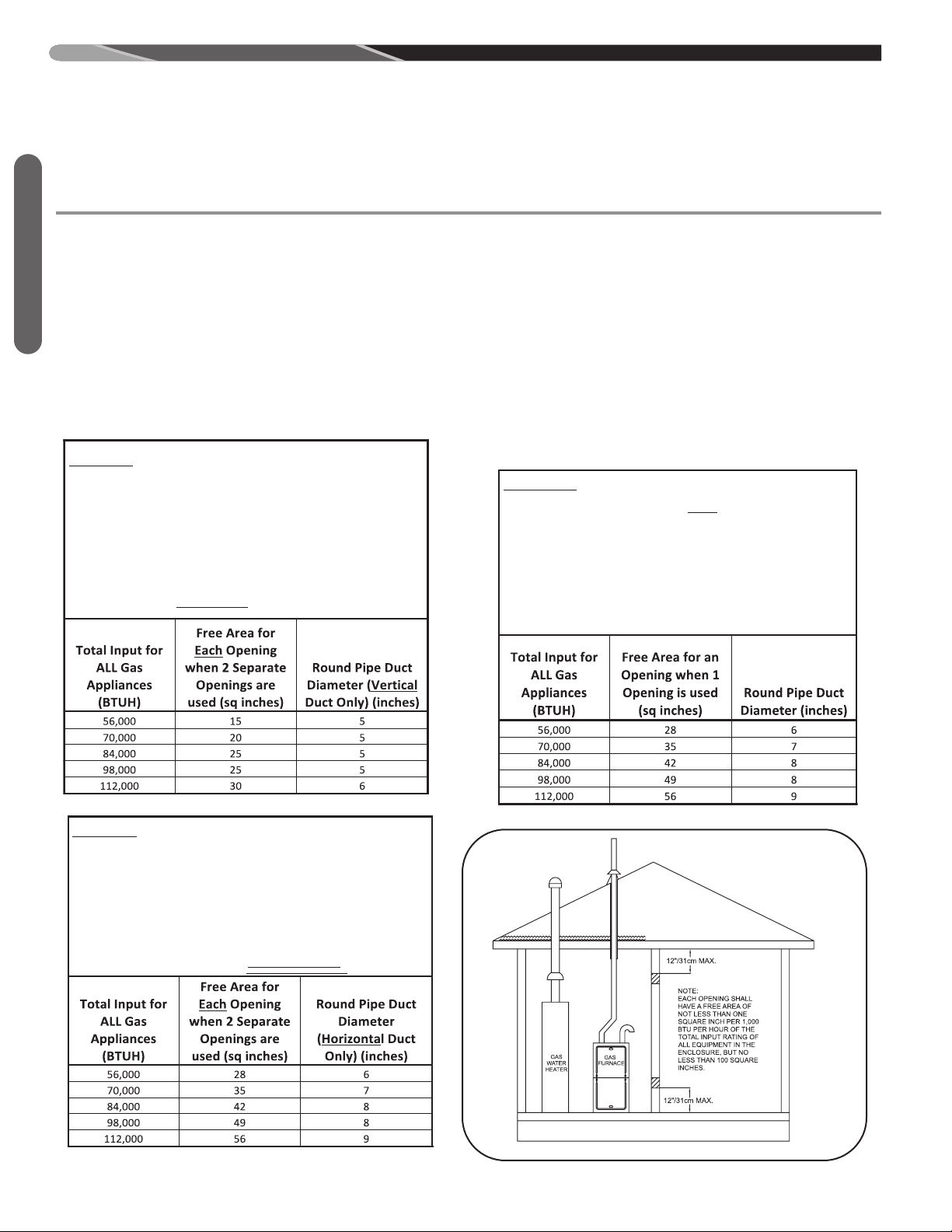
GENERAL VENTING REQUIREMENTS AND
GUIDELINES
NON-DIRECT VENT (cont.)
. Where directly communicating with the outdoors through
B. USING OUTDOOR AIR FOR COMBUSTION:
IMPORTANT: Do not take air from an attic space that is
equipped with power ventilation.
Venting
The confined space must communicate with the outdoors in
accordance with Methods 1 or 2 below. The minimum dimension of air openings shall not be less than 3 inches. Where
ducts are used, they shall be of the same cross-sectional
area as the free area of the openings to which they connect.
METHOD 1:
Two permanent openings, one located within 12 inches of the
top and one located within 12 inches of the bottom of the
enclosure, shall be provided. The openings shall communicate
directly, or by ducts, with the outdoors or spaces (crawl or
attic) that freely communicate with the outdoors.
TABLE 8: MINIMUM FREE AREA REQUIRED
FOR EACH OPENING (WHEN TWO OPENINGS
ARE USED) WITH A FURNACE:
1. LOCATED IN A CONFINED SPACE
2. USING OUTDOOR AIR FOR COMBUSTION
3. COMMUNICATING DIRECTLY TO THE
3. OUTSIDE THROUGH AN OPENING OR
3. THROUGH A VERTICAL DUCT.
A
an opening or where communicating to the outdoors through
vertical ducts as shown in Figure 12, each opening shall have
a minimum free area of 1 square inch for each 4,000 BTUH of
total appliance input rating of all equipment in the enclosure.
Table 8 below specifies the minimum area for each of the 2
combustion air openings and minimum round duct diameter
for direct openings and vertical ducting only.
B. Where communicating with the outdoors through horizontal
ducts, each opening shall have a minimum free area of 1
square inch for each 2,000 BTUH of total appliance input rating of all equipment in the enclosure (see Figure 13). Table 9
specifies the minimum area for each of the 2 combustion air
openings and minimum round duct diameter for horizontal
ducting only.
METHOD 2:
One permanent opening located within 12 inches of the top
TABLE 10: MINIMUM FREE AREA REQUIRED
FOR AN OPENING (WHEN ONE
OPENING IS
USED) WITH A FURNACE:
1. LOCATED IN A CONFINED SPACE
2. USING OUTDOOR AIR FOR COMBUSTION
3. COMMUNICATING DIRECTLY TO THE
3. OUTSIDE.
TABLE 9: MINIMUM FREE AREA REQUIRED
FOR EACH OPENING (WHEN TWO OPENINGS
ARE USED) WITH A FURNACE:
1. LOCATED IN A CONFINED SPACE
2. USING OUTDOOR AIR FOR COMBUSTION
3. COMMUNICATING DIRECTLY TO THE
3. OUTSIDE THROUGH A HORIZONTAL DUCT.
30
FIGURE 11
NON-DIRECT VENT
AIR FROM
HEATED
SPACE
ST-A1194-19
FIG C
 Loading...