

Page 1
WARNING:
Enabled
RECOGNIZE THIS SYMBOL
AS AN INDICATION OF
IMPORTANT SAFETY
INFORMATION
WARNING
THESE INSTRUCTIONS
ARE INTENDED AS AN AID
TO QUALIFIED, LICENSED
SERVICE PERSONNEL FOR
PROPER INSTALLATION,
ADJUSTMENT, AND
OPERATION OF THIS UNIT.
READ THESE INSTRUCTIONS
THOROUGHLY BEFORE
ATTEMPTING INSTALLATION
OR OPERATION. FAILURE
TO FOLLOW THESE
INSTRUCTIONS MAY
RESULT IN IMPROPER
INSTALLATION,
ADJUSTMENT, SERVICE,
OR MAINTENANCE
POSSIBLY RESULTING IN
FIRE, ELECTRICAL SHOCK,
PROPERTY DAMAGE,
PERSONAL INJURY, OR
DEATH.
VARIABLE SPEED R-410A
HEAT PUMP/ AIR CONDITIONING
OUTDOOR UNITS
INSTALLATION INSTRUCTIONS
(-)A15AZ(-)P16AZ/(-)A16AZ
(15/16 SEER2) EQUIPPED WITH
ECONET™ COMMUNICATIONS
Do not destroy this manual.
Please read carefully and
keep in a safe place for future
reference by a serviceman.
[ ] indicates metric conversions.
92-104921-25-04( / )
Printed in the USA
ISO 9001:2015
Page 2

CONTENTS
1.0 IMPORTANT SAFETY INFORMATION ............................................................3
2.0 GENERAL INFORMATION ...............................................................................4
2.1 Introduction ....................................................................................................4
2.2 Agency Performance Audit Testing Notice ...................................................4
2.3 Importance of Quality Installation..................................................................4
2.4 System Sizing and Selection ......................................................................... 4
2.5 Importance of Proper Indoor/Outdoor Match-Ups ........................................5
Contents
2.6 Checking Product Received ..........................................................................5
2.7 Compressor Break-In Notice .......................................................................5
2.0 GENERAL INFORMATION ...............................................................................5
3.0 UNIT SPECIFICATIONS ....................................................................................6
3.1 Model Number Nomenclature and Available Models .................................... 6
3.2 Electrical and Physical Data .......................................................................... 7
4.0 INSTALLATION ..................................................................................................8
4.1 Tools and Refrigerant ..................................................................................... 8
4.1.1 Tools Required for Installing and Servicing R-410A Models .................8
4.1.2 Specications of R-410A .......................................................................8
4.1.3 Quick-Reference Guide for R-410A ......................................................8
4.2 Choosing a Location ......................................................................................9
4.2.1 Allowable Clearances ............................................................................9
4.2.2 Operational Issues Related to Unit Location ........................................9
4.2.3 Corrosive Environment........................................................................ 10
4.2.4 Customer Satisfaction Issues .............................................................10
4.3 Unit Mounting ............................................................................................... 10
4.3.1 Unit Mounting Methods ....................................................................... 10
4.3.2 High Wind and Seismic Tie-Down Methods .......................................10
4.2 Choosing a Location (cont.) ......................................................................... 10
4.3.3 Elevating Unit ............................................................................................ 11
4.4.1 Replacing Existing Systems ................................................................ 12
4.4.2 Line Set Application Considerations ................................................... 12
4.4.2.1 Oil Return to Compressor ..............................................................12
4.4.2.2 Refrigerant Migration During Off Cycle ........................................ 12
4.4.2.3 Maximum Liquid Pressure Drop ................................................... 12
4.4.2.4 Liquid Line Refrigerant Flashing ................................................... 12
4.4 Refrigerant Line Set Selection ..................................................................... 12
4.4.2.5 Oil Level Adjustment for Long Line Set Applications ................... 13
4.4.2.6 Capacity Losses............................................................................13
4.4.3 Line Set Length and Fitting Losses.....................................................13
4.4.4 Liquid Line Selection ........................................................................... 14
4.4.5 Vapor Line Selection ........................................................................... 14
4.5 Line Set Installation .....................................................................................17
4.5.1 Important Tubing Installation Practices ............................................... 17
4.5.2 Relative Location of Indoor and Outdoor Units .................................. 18
4.5.2.1 Outdoor Unit Level or Near Level to Indoor Coil Line Set ............18
4.5 Line Set Installation (cont.) ..........................................................................18
4.5.2.2 Outdoor Unit Below Indoor Coil (Long Line Set Applications) ..... 19
4.5.2.3 Outdoor Unit Above Indoor Coil ................................................... 20
4.5.3 Tubing Connections ............................................................................ 21
4.6 Initial Leak Testing ......................................................................................22
4.7 Evacuation ...................................................................................................22
4.8 Final Leak Testing ........................................................................................ 23
4.9 Control Wiring .............................................................................................. 23
4.9.1 EcoNet™ Communications ...................................................................23
4.9.2 EcoNet™ Control Center Installation ...................................................23
4.9.3 EcoNet™ Communication Wiring Connections ...................................23
4.9.4 Conventional 24VAC Thermostat Control Wiring Connections .......... 24
4.9.5 For Installations with Only 2 Thermostat Wires...................................25
4.9 Control Wiring (cont.) ...................................................................................26
4.10 Power Wiring ..............................................................................................27
4.11 Grounding.......................................................................................................27
5.0 SYSTEM START-UP AND REFRIGERANT CHARGING ..............................28
5.1 System Start-Up Over view .......................................................................... 28
5.2 Initial Power-Up............................................................................................28
and EcoNet™ Communication Verification.........................................................28
5.3 EcoNet™ Control Center Set-Up ..................................................................28
5.4 Initial System ................................................................................................27
Start-Up .............................................................................................................. 27
5.5 Entering Charge Mode Using EcoNet™ Control Center Service Menu .......29
5.6 Entering Charge Mode When Using a Universal Outdoor Control ............. 29
5.7 Indoor Air-Flow Verification ........................................................................30
5.8 Refrigerant Charging ...................................................................................30
5.8.1 Measurement Device Set-Up .............................................................. 31
5.8.2 Preliminary Charging by Weight .........................................................31
5.8.3 Preliminary Charging by Pressures (Optional) ...................................31
5.8.4 Final Charging by Liquid Subcooling ..................................................30
5.8.5 R- 410A Temperature Pressure Chart ................................................. 30
5.9 Completing Installation ...............................................................................30
6.0 NORMAL SEQUENCE OF OPERATION ........................................................33
6.1 Cooling Mode ............................................................................................... 33
6.2 On-Demand Cooling Dehumidification ....................................................... 33
6.3 Low Ambient Cooling Mode .........................................................................33
6.4 Supplemental Electric
6.5 Dual Fuel Applications
6.6 Demand Defrost ...........................................................................................34
6.7 Sequence of Operation for Conventional 2-Stage 24VAC Thermostat Controls .. 35
7.0 COMPONENTS & CONTROLS .......................................................................36
7.1 E coNet™ Universal Outdoor Control (UODC) ..............................................36
7.1.1 Board Features and Connections .......................................................36
7.1.2 Factor y Superheat Setting......................................................................36
7.2 Power Inverter Compressor Control ............................................................37
8.0 ACTIVE SYSTEM PROTECTION FEATURES ...............................................38
8.1 Minimum Run Timer .....................................................................................38
8.2 Oil Return Cycle ...........................................................................................38
8.3 High Discharge Temperature.......................................................................38
8.4 High Discharge Pressure ............................................................................. 38
8.5 Low Suction Pressure
Loss of Charge ...................................................................................................38
8.6 Compressor Shut-Down Sequence for High or Low Refrigerant Pressure Fault .... 39
8.7 Overcurrent and Current Imbalance ............................................................39
8.8 Compressor Operation Outside Envelope .................................................. 39
8.9 Over and Under Voltage .............................................................................. 39
8.10 Inverter Over Temperature .........................................................................39
8.11 Controls and Communication Malfunction .................................................39
8.12 Sensor Failure Default Operation ..............................................................40
8.13 Exiting Active Protection Lock-Out Mode .................................................. 40
9.0 DIAGNOSTICS & TROUBLESHOOTING .......................................................41
9.1 Checking Transducers & Temperature Sensors ..........................................43
9.2 General Troubleshooting Guide ..................................................................45
9.3 Service Analyzer Char ts ..............................................................................46
9.4 Troubleshooting Tips.......................................................................................51
10.0 OUTDOOR UNIT MAINTENANCE ................................................................ 52
10.1 Outdoor Coil Cleaning ................................................................................52
10.2 Cabinet Cleaning and Care .......................................................................52
10.3 Motor Lubrication .......................................................................................52
10.4 Replacement Parts ....................................................................................52
11.0 WIRING DIAGRAM ........................................................................................53
12.0 APPENDIX ......................................................................................................55
12.1 Agency Performance Audit Test Instructions ............................................56
Heat in Heating Mode ................................................. 33
– Heating Mode ..........................................................34
/ ....................................................................................38
2
Page 3
1.0 IMPORTANT SAFETY INFORMATION
WARNINGS:
• These instructions are intended as an aid to qualified,
licensed service personnel for proper installation,
adjustment, and operation of this unit. Read these
instructions thoroughly before attempting installation
or operation. Failure to follow these instructions
may result in improper installation, adjustment,
service, or maintenance possibly resulting in
fire, electrical shock, property damage, personal
injury, or death.
• The unit must be permanently grounded. Failure
to do so can cause electrical shock resulting in
severe personal injury or death.
• Turn off electric power at the fuse box or service
panel before making any electrical connections.
• Complete the ground connection before making
line voltage connections. Failure to do so can
result in electrical shock, severe personal injury,
or death.
• Disconnect all power to unit before starting
maintenance. Failure to do so can cause electrical
shock resulting in severe personal injury or death.
• Never assume the unit is properly wired and/or
grounded. Always test the unit cabinet with a
noncontact voltage detector available at most
electrical supply houses or home centers before
removing access panels or coming into contact
with the unit cabinet.
• DO NOT use oxygen to purge lines or pressurize
system for leak test. Oxygen reacts violently with
oil, which can cause an explosion resulting in
severe personal injury or death.
• The top of the scroll compressor shell is hot. Touching
the compressor top may result in serious personal
injury.
• The manufacturer’s warranty does not cover any
damage or defect to the unit caused by the attachment
or use of any components, accessories, or devices
(other than those authorized by the manufacturer)
into, onto, or in conjunction with the heat pump. You
should be aware that the use of unauthorized
components, accessories, or devices may
adversely affect the operation of the heat pump
and may also endanger life and property. The
manufacturer disclaims any responsibility for such loss
or injury resulting from the use of such unauthorized
components, accessories, or devices.
• This product is not approved for installation at
6561 feet [2000 meters] above sea level or higher.
Installation at higher altitudes may result in control
and unit failures due to electrical arc tracking between
electrical components on the invertor drive control
board. Possibly resulting in fire, electrical shock,
property damage, personal injury, or death.
CAUTIONS:
• R-410A systems operate at approximately 60% higher
pressures (1.6 times) than R-22 systems. Do not use
R-22 service equipment or components on R-410A
equipment. Use appropriate care when using this
refrigerant. Failure to exercise care may result in
equipment damage or personal injury.
• Only match this outdoor unit with a matched indoor coil
or air handler approved for use with this outdoor unit
per the unit manufacturer’s specification sheet. The
use of unmatched coils or air handler will likely result
in a charge imbalance between the cooling and heating
modes which can cause unsatisfactory operation
including a high-pressure switch lockout condition.
• Only use indoor coils approved for use on R-410A
systems. An R-22 coil will have a TXV or fixed
expansion device that is not designed to operate
properly in an R-410A system and will result in serious
operational issues. The R-22 coil could also contain a
significant amount of mineral oil which is incompatible
with the POE oil used in R-410A systems and could
result in reliability issues with the compressor and
expansion devices.
• When the indoor coil or air handler is installed over
a finished ceiling and/or living area, it is required that
an auxiliary overflow pan be constructed and installed
under the entire indoor unit. Failure to do so can result
in property damage.
• UNIT MAY START SUDDENLY AND WITHOUT
WARNING. The blue cooling status LED shall blink
(1 second ON, 1 second OFF) if waiting for the short
cycle timer (LOCKTIMR) to expire, otherwise it shall
blink the first digit of the capacity percentage requested
(for example, blink 7 times for 70% capacity). At 100%
capacity the LED shall be solid on. The orange heating
status LED shall blink (1 second ON, 1 second OFF) if
waiting for the short cycle timer (LOCKTIMR) to expire,
otherwise it shall blink the first digit of the capacity
percentage requested (for example, blink 7 times for
70% capacity). At 100% capacity the LED shall be
solid on.
Safety
3
Page 4

2.0 GENERAL INFORMATION
WARNING:
Improper installation, or installation not made in
accordance with these instructions, can result
in unsatisfactory operation and/or dangerous
conditions and can cause the related warranty
not to apply.
2.1 Introduction
The (-)A15AZ/(-)P16AZ/(-)A16AZ series heat
pumps and condensing units are specifically
designed to operate with matching communicating
EcoNet™ enabled air-handlers, gas furnaces, and
Control Center. A conventional 24VAC 2-stage
thermostat can be used, but many features and
benefits are lost.
This installation instruction manual contains
complete instructions for installation and setup
using the EcoNet™ or conventional 24VAC 2-stage
General Information
controls. Please refer to the manufacturer's
specification sheets for complete performance
data, thermostat, and accessory listings.
The information contained in this manual has
been prepared to assist in the proper installation,
operation, and maintenance of the air conditioning
system.
Read this manual and any instructions packaged
with separate equipment required to make up the
system prior to installation. Homeowner should
retain this manual for future reference.
2.2 Agency Performance
Audit Testing Notice
For purposes of verifying or testing efficiency
ratings, the test procedure in Title 10 APPENDIX
M to Subpart B of Part 430 (Uniform Test Method
for Measuring the Energy Consumption of
Central Air Conditioners and Heat Pumps) and
the clarifying provisions provided in the AHRI
Operations Manual 210/240 that were applicable
at the date of manufacture should be used for
test set up and performance.
Should this unit be selected for performance audit
testing, follow the instructions included in the
Appendix (Section 12.1) of this manual.
4
2.3 Importance of Quality
Installation
A quality installation is critical to assure safety,
reliability, comfort, and customer satisfaction. Strict
adherence to applicable codes, the information in
this installation manual, the outdoor unit installation
manual, and the thermostat installation manual
are key to a quality installation. Read the entire
instruction manuals before starting the installation.
IMPORTANT: This product has been designed
and manufactured to meet certified AHRI capacity
and efficiency ratings with the appropriate outdoor
units. However, proper refrigerant charge, proper
airflow, and refrigerant line sizing are critical to
achieve optimum capacity and efficiency and to
assure reliable operation. Installation of this
product should follow the manufacturer’s refrigerant
charging and airflow instructions located in this
installation manual and the charging chart label
affixed to the outdoor unit. Failure to confirm
proper charge and airflow may reduce energy
efficiency and shorten equipment life.
The equipment has been evaluated in accordance
with the Code of Federal Regulations, Chapter XX,
Part 3280.
Install the unit in accordance with applicable
national, state, and local codes. Latest editions
are available from: “National Fire Protection
Association, Inc., Batterymarch Park, Quincy, MA
02269.” These publications are:
• ANSI/NFPA No. 70-(Latest Edition) National
Electrical Code.
• NFPA90A Installation of Air Conditioning and
Ventilating Systems.
• NFPA90B Installation of warm air heating and air
conditioning systems.
Install the unit in such a way as to allow necessary
access to the coil/filter rack and blower/control
compartment.
2.4 System Sizing and
Selection
Before specifying any heat pump equipment, a
survey of the structure and heat loss and heat
gain calculations must be made. A heat loss
calculation involves identifying all surfaces and
openings that lose heat to the surrounding air in
the heating mode and quantifying that heat loss. A
heat gain calculation makes similar measurements
and determines the amount of heat required to
be removed in the cooling mode. A heat gain
calculation also calculates the extra heat load
caused by sunlight and by humidity removal. These
factors must be considered before selecting a heat
pump system to provide year-round comfort. The
Air Conditioning Contractors of America (ACCA)
Page 5

2.0 GENERAL INFORMATION
Manual J method of load calculation is one
recognized procedure for determining the heating
and cooling load.
After the proper equipment combination has
been selected, satisfying both sensible and
latent requirements, the system must be properly
installed. Only then can the system provide the
comfort it was designed to provide.
There are several factors that installers must
consider.
• Outdoor unit location
• Indoor unit blower speed and airflow
• Proper equipment evacuation
• Supply and return air duct design and sizing
• Refrigerant charge
• System air balancing
• Diffuser and return air grille location and sizing
IMPORTANT: Excessive use of
elbows in the refrigerant line set can produce
excessive pressure drop. Follow industry
best practices for installation. Installation
and commissioning of this equipment is to
be performed by trained and qualified HVAC
professionals. For technical assistance, contact
your Distributor Service Coordinator.
shipping company. Check model number, electrical
characteristics, and accessories to determine if they
are correct. Check system components (indoor coil,
outdoor unit, air handler/furnace, etc.) to make sure
they are properly matched.
2.7 Compressor Break-In
Notice
Prior to agency testing, system must be operated
for 20 hours at 115ºF [46.1ºC] outdoor ambient
temperature with 80ºF [26.7ºC] dry bulb 75ºF
[23.9ºC] wet bulb indoor ambient temperature to
break the compressor in.
General Information
2.5 Importance of Proper
Indoor/Outdoor Match-Ups
To assure many years of reliable operation
and optimum customer comfort and to assure
the outdoor unit warranty remains valid, an airhandler model or indoor coil/furnace combination
should be selected that is properly matched to the
outdoor unit. This is especially critical for heat
pump systems to assure proper refrigerant charge
balance between the cooling and heating modes.
The recommended approach is to select an airhandler or indoor coil and gas furnace that has an
AHRI match with the outdoor unit. Refer to the
AHRI directory at www.ahridirectory.org to confirm
the air-handler and outdoor unit are a certified
combination in the AHRI Directory.
2.6 Checking Product
Received
Upon receiving unit, inspect it for any shipping
damage. Claims for damage, either apparent or
concealed, should be filed immediately with the
Unit Specications
5
Page 6
3.0 UNIT SPECIFICATIONS
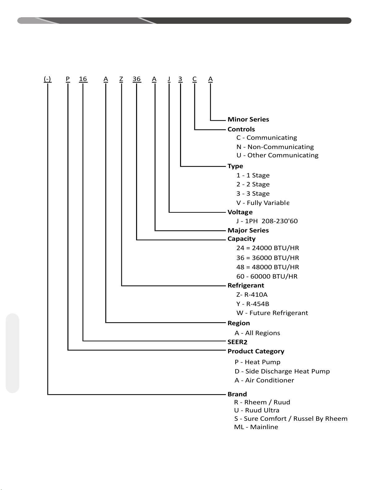
(-) P 16
A
Z36A
J
3 C
A
Minor Series
Controls
C - Communicating
N - Non-Communicating
U - Other Communicating
Type
1 - 1 Stage
2 - 2 Stage
3 - 3 Stage
V - Fully Variabl
e
Voltag
e
J - 1PH 208-230'60
Major Series
Capacity
24 = 24000 BTU/HR
36 = 36000 BTU/HR
48 = 48000 BTU/HR
60 - 60000 BTU/HR
Refrigerant
Z- R-410A
Y - R-454B
W - Future Refrigerant
Region
A - All Regions
SEER
2
Product Category
P - Heat Pump
D - Side Discharge Heat Pump
A - Air Conditioner
Brand
R - Rheem / Ruud
U - Ruud Ultra
ML - Mainline
S - Sure Comfort / Russel By Rheem
3.1 Model Number Nomenclature and Available Models
Unit Specications
6
Page 7
',0(16 6,21
“L”
“W”
“H”
ST-A1226-02-00
1
2
3
3.0 UNIT SPECIFICATIONS
3.1 Model Number Nomenclature and Available Models (cont.)
AVAILABLE MODELS
(-)A15AZ24AJ3CA (-)A16AZ24AJ3CA (-)P16AZ24AJ3CA
(-)A15AZ36AJ3CA (-)A16AZ36AJ3CA (-)P16AZ36AJ3CA
(-)A15AZ48AJ3CA (-)A16AZ48AJ3CA (-)P16AZ48AJ3CA
(-)A15AZ60AJ3CA (-)A16AZ60AJ3CA (-)P16AZ60AJ3CA
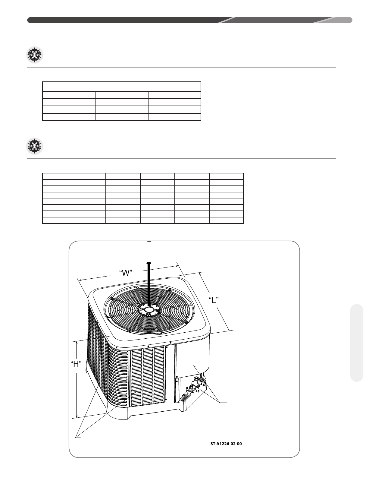
3.2 Electrical and Physical Data
(-
)P16AZ 24A 36A 48A 60A
Height "H" inches [cm]
Length "L' inches [cm]
Width "W" inches [cm]
(-)RA15AZ/(-
Height "H" inches [cm]
Length "L' inches [cm]
Width "W" inches [cm]
)A16AZ 24A 36A 48A 60A
27 [68.6] 35 [88.9] 35 [88.9] 45 [114.3]
29.75 [75.6] 33.75 [85.7] 33.75 [85.7] 35.75 [90.8]
29.75 [75.6] 33.75 [85.7] 33.75 [85.7] 35.75 [90.8]
27 [68.6] 27 [68.6] 31 [78.7] 31 [78.7]
29.75 [75.6] 33.75 [85.7] 33.75 [85.7] 35.75 [90.8]
29.75 [75.6] 33.75 [85.7] 33.75 [85.7] 35.75 [90.8]
ALLOW 60" [152.4 cm] OF CLEARANCE
Unit Specications
SERVICE PANELS/
INLET CONNECTIONS /
HIGH & LOW VOLTAGE
ACCESS ALLOW
24" [61.0 cm] OF
CLEARANCE
AIR INLET LOUVERS ALLOW
6" [15.2 cm] OF CLEARANCE ALL SIDES
12" [30.5 cm] RECOMMENDED
7
Page 8
4.0 INSTALLATION
1
2
3
4
5
6
7
8
9
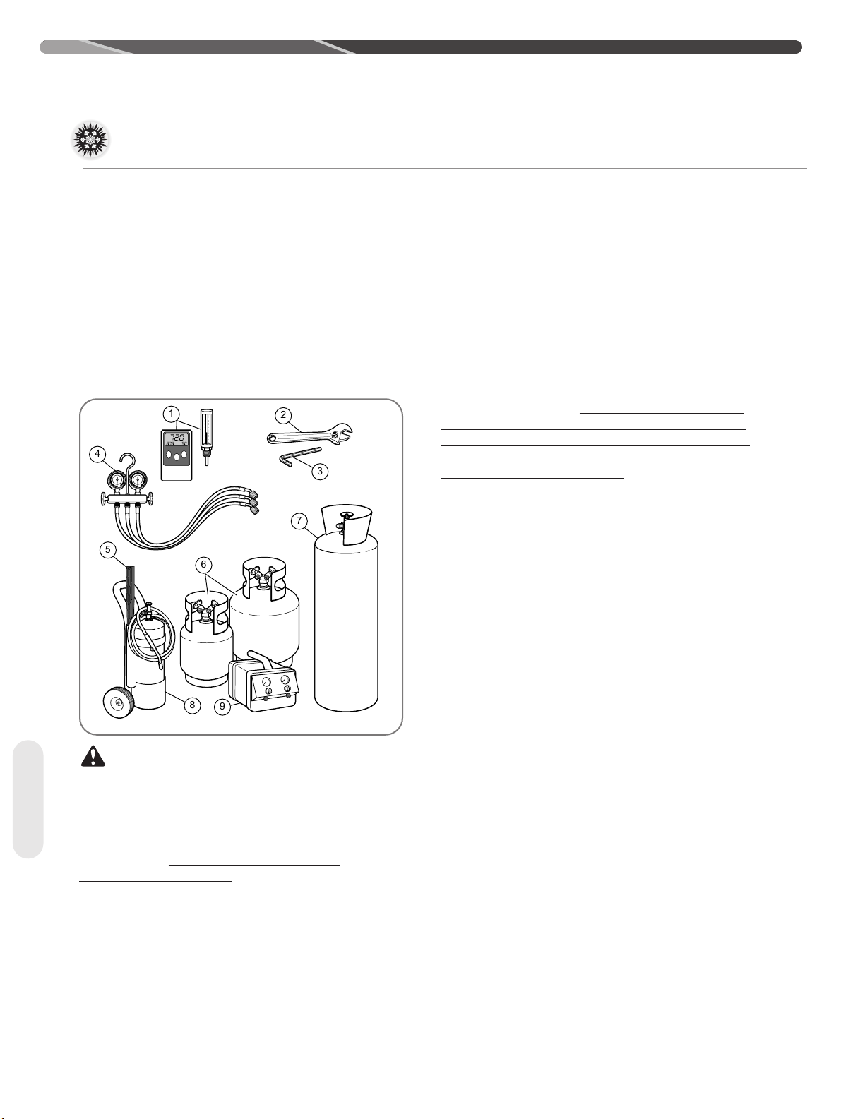
4.1 Tools and Refrigerant
4.1.1 Tools Required for Installing
and Servicing R-410A Models
Manifold Sets:
– Up to 800 PSIG [5,516 kPa] High-Side
– Up to 250 PSIG [1,724 kPa] Low-Side
– 550 PSIG [3,792 kPa] Low-Side Retard
Manifold Hoses:
– Service Pressure Rating of 800 PSIG [5,516 kPa]
Recovery Cylinders:
– 400 PSIG [2,758 kPa] Pressure Rating
– Dept. of Transportation 4BA400 or BW400
approximately 60% (1.6 times) greater than
R-22. Recovery and recycle equipment, pumps,
hoses, and the like must have design pressure
ratings appropriate for R-410A. Manifold sets need
to range up to 800 psig [5,516 kPa] high-side and
250 psig [1,724 kPa] low-side with a 550 psig
[3,792 kPa] low-side retard. Hoses need to have
a service pressure rating of 800 psig [5,516 kPa].
Recovery cylinders need to have a 400 psig [2,758
kPa] service pressure rating, DOT 4BA400 or DOT
BW400.
Combustibility: At pressures above 1
atmosphere, a mixture of R-410A and air can
become combustible. R-410A and air should
never be mixed in tanks or supply lines or
be allowed to accumulate in storage tanks.
Leak checking should never be done with a
mixture of R-410A and air. Leak-checking can
be performed safely with nitrogen or a mixture of
R-410A and nitrogen.
4.1.3 Quick-Reference Guide for
R- 410A
• R-410A refrigerant operates at approximately
60% higher pressure (1.6 times) than R-22.
Ensure that servicing equipment is designed to
operate with R-410A.
• R-410A refrigerant cylinders are light rose in
color.
• R-410A, as with other HFCs, is only compatible
with POE oils.
• Vacuum pumps will not remove moisture from
POE oil used in R-410A systems.
• R-410A systems are to be charged with liquid
CAUTION: R-410A systems operate
at higher pressures than R-22 systems. Do not use
R-22 service equipment or components on R-410A
Tools
equipment.
4.1.2 Specications of R-410A
Application: R-410A is not a drop-in
replacement for R-22. Equipment designs must
accommodate its higher pressures. It cannot be
retrofitted into R-22 heat pumps.
Physical Properties: R-410A has an atmospheric
boiling point of -62.9°F [-52.7°C] and its saturation
pressure at 77°F [25°C] is 224.5 psig [1,548 kPa].
Composition: R-410A is a near-azeotropic
mixture of 50% by weight difluoromethane (HFC-
32) and 50% by weight pentafluoroethane (HFC-
125).
Pressure: The pressure of R-410A is
refrigerants. Prior to March 1999, R-410A
refrigerant cylinders had a dip tube. These
cylinders should be kept upright for equipment
charging. Post-March 1999 cylinders do not have
a dip tube and should be inverted to ensure liquid
charging of the equipment.
• Do not install a suction line filter drier in the liquid
line.
• A factory-approved bi-flow liquid line filter drier
is shipped with every unit and must be installed
in the liquid line at the time of installation. Only
manufacturer-approved liquid line filter driers
should be used. Filter driers must have a working
pressure rating of at least 600 psig [4,137 kPa].
The filter drier will only have adequate moistureholding capacity if the system is properly evacuated.
• Desiccant (drying agent) must be compatible for
POE oils and R-410A refrigerant.
8
Page 9
4.2 Choosing a Location
ST-A1226-04-00
1
2
3
4
4.0 INSTALLATION
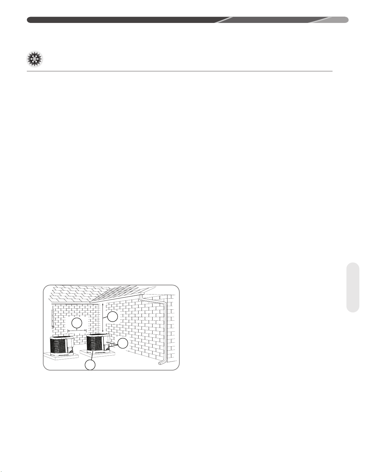
4.2.1 Allowable Clearances
12" [30.5 cm] to side intake louvers
24" [61.0 cm] to service access panels
60" [152.4 cm] vertical for fan discharge
If space limitations exist, the following clearances
will have minimal impact to capacity and efficiency
and are permitted:
Single-Unit Applications: Minimum of 6" [15.2
cm] to side intake louvers. DO NOT reduce the 60"
[152.4 cm] for fan discharge or the 24" [61.0 cm]
service clearances.
Multiple-Unit Applications: For units positioned
next to each other, a minimum of 6" [15.2 cm]
clearance between units is recommended for 2 ton
models and 9" [22.9 cm] for 3 ton to 5 ton models.
Do not reduce the 60" [152.4 cm] for fan discharge
or the 24" [61.0 cm] service clearances.
IMPORTANT: Consult local and
national building codes and ordinances for special
installation requirements. Following location
information will provide longer life and simplified
servicing of the outdoor heat pump.
NOTICE: These units must be installed
outdoors. No ductwork can be attached, or other
modifications made, to the discharge grille.
Modifications will affect performance or operation.
4.2.2 Operational Issues
Related to Unit Location
IMPORTANT: Locate the unit in a
manner that will not prevent, impair, or compromise
the performance of other equipment installed
in proximity to the unit. Maintain all required
minimum distances to gas and electric meters,
dryer vents, and exhaust and inlet openings. In
the absence of national codes or manufacturers’
recommendations, local code recommendations
and requirements will take precedence.
• Refrigerant piping and wiring should be properly
sized and kept as short as possible to avoid
capacity losses and increased operating costs.
• Locate the unit where water runoff will not create
a problem with the equipment. Position the unit
away from the drip edge of the roof whenever
possible. Units are weatherized, but can be
affected by the following:
• Water pouring into the unit from the junction
of rooflines, without protective guttering. Large
volumes of water entering the heat pump while
in operation can impact fan blade or motor life,
and coil damage may occur to a heat pump if
moisture cannot drain from the unit under freezing
conditions.
• Freezing moisture or sleeting conditions can
cause the cabinet to ice-over prematurely and
prevent heat pump operation, requiring backup
heat, which generally results in less economical
operation It is highly recommended to switch the
EcoNet™ Control Center or thermostat to the
"Emergency Heat" mode during freezing rain
or sleeting conditions to prevent damage to the
outdoor coil from ice accumulating on the fan
blade.
• Closely follow the clearance recommendations in
section 4.2.1.
• 24" [61.0 cm] to the service panel access.
• 60" [152.4 cm] above the fan discharge (unit
top) to prevent recirculation.
• 6" [15.2 cm] to the coil grille air inlets
with 12" [30.5 cm] minimum recommended.
Location
9
Page 10

4.0 INSTALLATION
4.2 Choosing a Location (cont.)
4.2.3 Corrosive Environment
The metal parts of this unit may be subject to rust or
deterioration if exposed to a corrosive environment.
This oxidation could shorten the equipment’s useful
life.
Corrosive elements include, but are not limited to,
salt spray, fog or mist in seacoast areas, sulphur or
chlorine from lawn watering systems, and various
chemical contaminants from industries such as
paper mills and petroleum refineries.
If the unit is to be installed in an area where
contaminants are likely to be a problem, special
attention should be given to the equipment location
and exposure.
• Avoid having lawn sprinkler heads spray directly on
the unit cabinet.
• In coastal areas, locate the unit on the side of the
building away from the waterfront.
• Shielding provided by a fence or shrubs may give
some protection, but cannot violate minimum
airflow and service access clearances.
WARNING: Disconnect all power
to unit before starting maintenance. Failure to do
so can cause electrical shock resulting in severe
personal injury or death.
Regular maintenance will reduce the buildup of
contaminants and help to protect the unit’s finish.
• Frequent washing of the cabinet, fan blade, and
coil with fresh water will remove most of the salt or
Location
other contaminants that build up on the unit.
• Regular cleaning and waxing of the cabinet
with a good automobile polish will provide some
protection.
• A good liquid cleaner may be used several times
a year to remove matter that will not wash off with
water.
4.3 Unit Mounting
4.3.1 Unit Mounting Methods
The outdoor heat pump unit may be mounted in a
number of ways. The most common method is on
the ground mounted on a concrete or pre-fabricated
pad. It can also be mounted on a ground or roof
mounted metal frame, wooden frame, or 4” x 4”
[10.2 cm x 10.2 cm] wooden stringers. It is extremely
important to properly secure the unit to the pad or
frame so it does not shift during high winds, seismic
events, or other outside forces to eliminate the
possibility of a safety hazard or physical damage to
the unit. Local codes in regions subject to frequent
hurricanes and seismic events will dictate specific
mounting requirements and must be followed. It is
also important to elevate the heat pump in areas
that receive a significant amount of snowfall so
accumulated snow does not block the outdoor
coil and interfere with drainage of water during
the defrost cycle. Refer to Section 4.3.4 for typical
ground snow levels for different regions of the USA.
4.3.2 High Wind and Seismic TieDown Methods
The manufacturer-approved/recommended method
is a guide to securing equipment for wind and
seismic loads. Other methods might provide the
same result, but the manufacturer method is the
only one endorsed by the manufacturer for securing
equipment where wind or earthquake damage
can occur. Additional information is available on
the manufacturer's website or from the wholesale
distributor.
4.2.4 Customer Satisfaction Issues
• The heat pump should be located away from the
living, sleeping, and recreational spaces of the
owner and those spaces on adjoining property.
• To prevent noise transmission, the mounting pad
for the outdoor unit should not be connected to
the structure and should be located a sufficient
distance above grade to prevent ground water from
entering the unit.
10
Page 11
4.0 INSTALLATION
ST-A1226-03-00
1
2
3
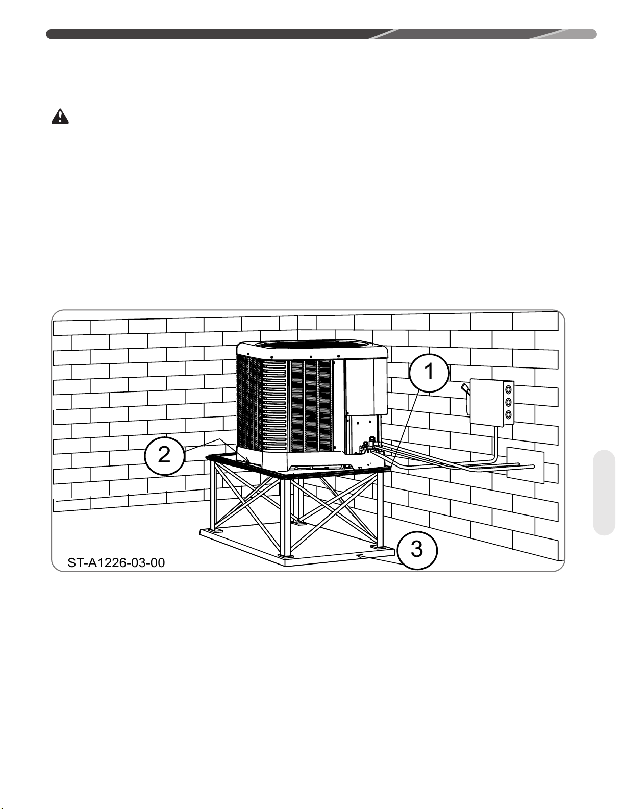
4.3.3 Elevating Unit
WARNING: Secure an elevated unit and its elevating stand in order to prevent tipping. Failure to
do so may result in severe personal injury or death.
If elevating the heat pump, either on a flat roof or on a slab, observe the following guidelines.
• If elevating a unit on a flat roof, use 4" x 4"
[10.2 cm x 10.2 cm] or equivalent stringers positioned to distribute unit weight evenly and prevent noise and
vibration.
• Heat pump products will need to be elevated per local climate and code requirements to provide clearance
above the estimated snowfall level to ensure the unit will be protected from damage. Failure to follow these
instructions may result in equipment damage and improper operation.
NOTICE: Do not block drain openings on bottom of unit.
• If unit must be elevated because of anticipated snowfall, secure unit and elevating stand such that unit and/or
stand will not tip over or fall off. Keep in mind that someone may try to climb on unit.
Location
11
Page 12

4.0 INSTALLATION
4.4 Refrigerant Line Set Selection
4.4.1 Replacing Existing
Systems
To prevent failure of a new unit, the existing line set
must be correctly sized for the new unit and must
be cleaned or replaced. Care must be taken so
the expansion device is not plugged. For new and
replacement units, a liquid line filter drier must be
installed and the line set must be properly sized. Test
the oil for acid. If it tests positive for acid, a suction
line filter drier is mandatory.
IMPORTANT: When replacing an
R-22 unit with an R-410A unit, either replace
the line set or ensure that residual mineral oil is
drained from existing lines including oil trapped in
low spots.
4.4.2 Line Set Application
Considerations
The following are special considerations that need
to be addressed when selecting and installing a line
set.
• Additional refrigerant charge
• Fitting losses and maximum equivalent length
considerations
• Refrigerant migration during the off cycle
• Oil return to the compressor
• Capacity losses
• System oil level adjustment
4.4.2.2 Refrigerant Migration During O
Cycle
Long line set applications can require a considerable amount of additional refrigerant. This additional refrigerant needs to be managed throughout the
entire ambient operating envelope that the system will go through during its life cycle. Off-Cycle
migration is where excess refrigerant condenses
and migrates to the coldest and/or lowest part of
the system. Excessive build-up of refrigerant at the
compressor will result in poor reliability and noisy
operation during startup. Section 4.5.2 demon-
strates the required unit conguration for different
applications.
4.4.2.3 Maximum Liquid Pressure Drop
The total liquid line pressure drop must not exceed
50 psig [345 kPa] to assure a solid column of liquid
at the metering device and stable control of superheat. Be sure to account for vertical separation,
elbows, lter driers, solenoid valves, sight glasses,
and check valves when calculating liquid line pressure drop.
4.4.2.4 Liquid Line Refrigerant Flashing
Excessive pressure drop and heat gain in long liq-
uid lines can result in the refrigerant ashing into a
vapor before it reaches the expansion device which
will dramatically reduce the capacity and efciency
of the system. For this reason, the liquid line must
be sized properly using Table 2 and must be insulated in unconditioned spaces.
Tubing
12
4.4.2.1 Oil Return to Compressor
Small amounts of compressor crankcase oil is
picked up and carried out of the compressor by the
moving refrigerant and is circulated through the
system along with the refrigerant before it returns to
the compressor crankcase. It is critical to the life of
the compressor for the oil to be able to return to the
compressor to maintain an adequate level of oil in
the compressor crankcase. Oversized vapor lines
result in inadequate refrigerant velocities to carry
the oil along with the refrigerant and will cause the
oil to accumulate in the low spots in the vapor line
instead of being returned to the compressor crankcase. This is especially true for long line lengths.
Variable speed systems present an additional challenge due to the fact that the system operates at
a signicantly reduced refrigerant ow rate for a signicant percentage of operating time. Only use the
vapor line sizes listed in Table 2 to assure proper oil
return. DO NOT oversize vapor line!
Page 13
4.0 INSTALLATION
4.4.2.5 Oil Level Adjustment for Long Line
Set Applications
Additional oil may need to be added if refrigerant is
added during installation. If the system contains more
than 20 lbs [9 kg] of refrigerant charge, add 1 uid oz of
POE oil for every 5 lbs [13 ml/kg] of refrigerant charge
over 20 lbs [9 kg].
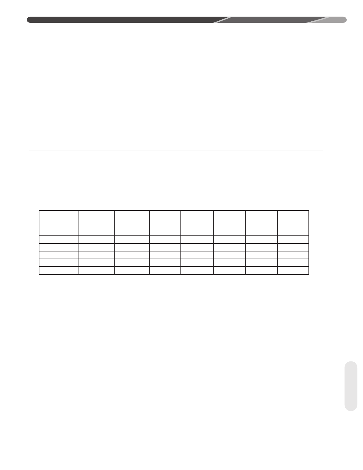
4.4.3 Line Set Length and Fitting Losses
Refrigerant tubing is measured in terms of actual length
and equivalent length. Actual length is used for refrigerant charge applications. Equivalent length takes into
account pressure losses from tubing length, ttings,
Table 1
Line Size
in [mm]
3/8 [9.53] 1.3 [0.40] 0.8 [0.24] 0.3 [0.09] 6 [1.8 3] 4 [1.22] 0.4 [0.12] 6 [1.83]
1/2 [12 .71] 1.4 [0.43] 0.9 [0.27] 0.4 [0.12] 9 [2.74] 5 [1.52] 0.6 [0.18] 6 [1. 83]
5/8 [15. 88 ] 1.5 [0.46] 1 [0.30] 0.5 [0.15] 12 [3.66] 6 [1.8 3] 0.8 [0.24] 6 [1.8 3]
3/4 [19.05] 1.9 [0.5 8] 1.3 [ 0.4 0] 0.6 [0.18] 14 [4.27] 7 [2.13 ] 0.9 [0.27] 6 [1. 83]
7/8 [22.23] 2.3 [0.70] 1.5 [0.46] 0.7 [0.21] 15 [4.57] 8 [2.44] 1 [0.30] 6 [1. 83]
1-1/8 [2 8. 58 ] 2.7 [0.82] 1.8 [0.5 5] 0.9 [0.27] 22 [ 6.71] 12 [3.66] 1.5 [0.46] 6 [1. 83]
90° Short
Radius
Elbow
90° Long
Radius
Elbow
45°
Elbow
4.4.2.6 Capacity Losses
Long line lengths can result in a reduction in capacity
due to vapor line pressure drop and heat gain or loss.
Refer to Table 2 for capacity loss multipliers for various
vapor line diameters and equipment line lengths. This
table does not account for any capacity loss due to heat
gain or loss from the environment. It is extremely important not to oversize the vapor line to minimize capacity loss at the expense of proper oil return. If the table
shows an “NR” for a particular vapor line diameter and
length, or, if a vapor line diameter is not listed, oil return
will not be adequate.
vertical separation, accessories, and lter driers. The
table below references different commonly used equivalent lengths.
Solenoid
Valve
Check
Valve
Sight
Glass
Filter
Drier
13
Tubing
Page 14
4.0 INSTALLATION
4.4.4 Liquid Line Selection
The purpose of the liquid line is to transport warm
sub-cooled liquid refrigerant between the outdoor
unit to the indoor unit in the cooling mode. In the
heating mode, the liquid line returns sub-cooled
liquid from the indoor unit to the outdoor unit. It is
important not to allow the refrigerant to ash into
superheated vapor prior to entering the expansion
device of the indoor coil or outdoor unit. Flashing of
refrigerant can occur for the following reasons:
• Low refrigerant charge
• Improperly selected liquid line size
• Absorption of heat prior to expansion device
• Excessive vertical separation between the outdoor
unit and indoor coil
• Restricted liquid linear lter drier
• Kinked liquid line
The total pressure drop allowed for the liquid line is
50 PSI [345 kPa]. The procedure for selecting the
proper liquid line is as follows:
• Measure the total amount of vertical separation
between the outdoor unit and indoor coil.
Example Table (Excerpt from Table 2A)
• Measure the total indoor length of liquid line required.
• Add all of the equivalent lengths associated with
any ttings or accessories using Table 1.
• Add the linear length to the total tting equivalent
length. This will equal your total equivalent line
length.
• Reference Table 2 to verify the calculated equivalent length is acceptable with the required vertical
separation and diameter of liquid line.
Example: A 3-ton heat pump unit is installed 25’
below the indoor unit, requires a 75’ of 1/2” diameter
liquid line, 3/4" vapor line, 4 90° LR elbows and a
lter drier.
• Fitting Equivalent Length (ft.) = 4 × .9' + 6' = 9.6’
• Total Equivalent Length (ft.) = 75’ + 9.6' = 84.6’
This application is acceptable because the 25’ vertical rise is less than the maximum rise of 50’ for this
application.
Allowable
Vapour
Line
Size
Unit Size
3 To n
Allowable
Liquid Line
Size
5/16" 5/8" 25 / 0.99 50 / 0.97 50 / 0.95 50 / 0.93 36 / 0.91 NR
3/8" 5/8" 25 / 0.99 50 / 0.97 50 / 0.95 50 / 0.93 50 / 0.91 NR
5/16" 3/4" 25 / 1.00 50 / 0.99 50 / 0.99 50 / 0.98 36 / 0.97 20 / 0.96
3/8" 3/4" 25 / 1.00 50 / 0.99 50 / 0.99 50 / 0.98 50 / 0.97 50 / 0.96
1/2" 3/4" 25 / 1.00 50 / 0.99 50 / 0.99 50 / 0.98 50 / 0.97 50 / 0.96
4.4.5 Vapor Line Selection
The purpose of the vapor line is to return superheated vapor to the condensing unit from the indoor coil
in the cooling mode. While in the heating mode, the
vapor line transports discharge vapor to the indoor
coil from the outdoor unit. Proper vapor line sizing
is important because it plays an important role in
Tubing
returning oil to the compressor to prevent potential
damage to the bearings, valves, and scroll sets.
Also, an improperly sized vapor line can dramatically reduce capacity and performance of the system.
The procedure for selecting the proper vapor line is
as follows:
Outdoor Unit ABOVE or BELOW Indoor Unit
Equivalent Length (Feet)
< 25 26-50 51-75 76-100 101-125 126-150
Maximum Vertical Separation / Capacity Multiplier
• Determine the total linear length of vapor line
required.
• Add all of the equivalent lengths associated with
any ttings or accessories using Table 1.
• Add the linear length and total tting equivalent
length. This will equal your total equivalent line
length.
• Reference Table 2 to verify that the calculated
equivalent length falls within the compatibility
region of the chart.
• Verify capacity loss is acceptable for the application.
14
Page 15
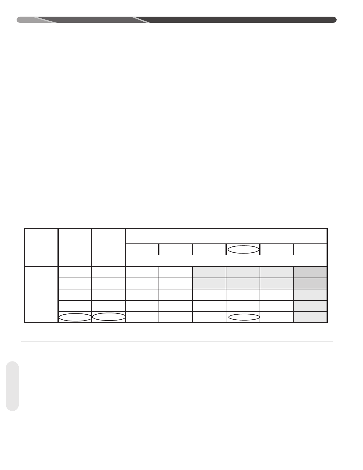
4.0 INSTALLATION
Table 2A: Refrigerant Line Sizing Chart (English Units)
15/16 SEER2 Variable Speed Heat Pumps/Air Conditioner
Outdoor Unit ABOVE or BELOW Indoor Unit
Equivalent Length (Feet)
Maximum Vertical Separation / Capacity Multiplier
Unit Size
2.0 Ton
*SEE
NOTE 3
3 To n
4 To n
5 To n
**SEE
NOTE 4
Allowable
Liquid Line
Size
1/4" 5/8" 25 /1.00 50 / 0.99 33 / 0.98 6 / 0.97 NR NR
5/16" 5/8" 25 /1.00 50 / 0.99 33 / 0.98 50 / 0.97 50 / 0.96 50 / 0.95
3/8" 5/8" 25 /1.00 50 / 0.99 33 / 0.98 50 / 0.97 50 / 0.96 50 / 0.95
1/4" 3/4" * 25 /1.0 0 50 / 1.00 33 / 0.99 6 / 0.99 NR NR
5/16" 3/4" * 25 /1.00 50 / 1.00 50 / 0.99 50 / 0.99 50 / 0.99 50 / 0.98
3/8" 3/4" * 25 /1.0 0 50 / 1.00 50 / 0.99 50 / 0.99 50 / 0.99 50 / 0.98
5/16" 5/8" 25 / 0.99 50 / 0.97 50 / 0.95 50 / 0.93 36 / 0.91 NR
3/8" 5/8" 25 / 0.99 50 / 0.97 50 / 0.95 50 / 0.93 50 / 0.91 NR
5/16" 3/4" 25 / 1.00 50 / 0.99 50 / 0.99 50 / 0.98 36 / 0.97 20 / 0.96
3/8" 3/4" 25 / 1.00 50 / 0.99 50 / 0.99 50 / 0.98 50 / 0.97 50 / 0.96
1/2" 3/4" 25 / 1.00 50 / 0.99 50 / 0.99 50 / 0.98 50 / 0.97 50 / 0.96
3/8" 3/4" 25 / 0.99 50 / 0.98 50 / 0.96 50 / 0.95 50 / 0.93 50 / 0.92
1/2" 3/4" 25 / 0.99 50 / 0.98 50 / 0.96 50 / 0.95 50 / 0.93 50 / 0.92
3/8" 7/8" 25 / 1.00 50 / 0.99 50 / 0.99 50 / 0.98 50 / 0.98 50 / 0.97
1/2" 7/8" 25 / 1.00 50 / 0.99 50 / 0.99 50 / 0.98 50 / 0.98 50 / 0.97
3/8" 3/4" 25 / 0.98 50 / 0.97 50 / 0.95 50 / 0.93 46 / 0.91 NR
1/2" 3/4" 25 / 0.98 50 / 0.97 50 / 0.95 50 / 0.93 50 / 0.91 NR
3/8" 7/8" 25 / 0.99 50 / 0.99 50 / 0.98 50 / 0.97 50 / 0.96 38 / 0.95
1/2" 7/8" 25 / 0.99 50 / 0.99 50 / 0.98 50 / 0.97 50 / 0.96 50 / 0.95
3/8" 1-1/8 " ** 25 / 1.00 50 / 1.00 50 / 1.00 50 / 0.99 50 / 0.99 38 / 0.99
1/2" 1-1/8" * * 25 / 1.00 50 / 1.00 50 / 1.00 50 / 0.99 50 / 0.99 50 / 0.99
Allowable
Vapour
Line
Size
< 25 26-50 51-75 76-100 101-125 126-150
Notes:
1) Do not exceed 150 ft linear line length.
2) Do not exceed 50 ft vertical separation between indoor and outdoor units.
3) * 3/4" vapour line should only be used for 2 ton systems if outdoor unit is below or at same level as indoor
unit to assure proper oil return.
4) ** 1-1/8" vapour line should only be used for 5 ton systems if outdoor unit is below or at same level as indoor
unit to assure proper oil return.
5) Always use the smallest liquid line allowable to minimize refrigerant charge.
6) Applications shaded in light Gray indicate capacity multipliers between 0.90 and 0.96 which are not
recommended, but are allowed.
7) Applications shaded in dark Gray are not recommended due to excessive liquid or suction pressure drop.
Tubing
15
Page 16
4.0 INSTALLATION
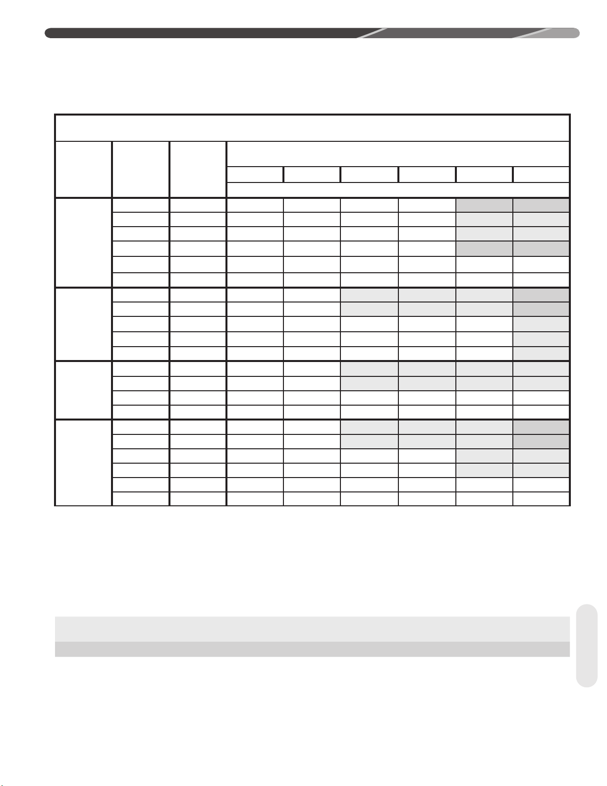
Table 2B: Refrigerant Line Sizing Chart (Metric Units)
15/16 SEER2 Variable Speed Heat Pumps/Air Conditioner
Allowable
Unit Size
7.0 K W
[2.0 Ton]
*SEE
NOTE 3
10.6 KW
[3 Ton]
14 .1 K W
[4 To n ]
17. 6 KW
[5 Ton]
**SEE
NOTE 4
Notes:
1) Do not exceed 46 meters linear line length.
2) Do not exceed 15 meters vertical separation between indoor and outdoor units.
3)
*19.05mm [3/4 in.] vapour line should only be used for 2 ton systems if outdoor unit is below or at same level as indoor unit to assure proper oil
return.
4)
**28.58mm [1-1/8 in.] vapour line should only be used for 5 ton systems if outdoor unit is below or at same level as indoor unit to assure proper oil
return.
5) Always use the smallest liquid line allowable to minimize refrigerant charge.
6) Applications shaded in light Gray indicate capacity multipliers between 0.90 and 0.96 which are not recommended, but are allowed.
7) Applications shaded in dark Gray are not recommended due to excessive liquid or suction pressure drop.
Liquid Line
Size
mm [in.]
6.35 [1/4] 15.88 [5/8] 8 / 1.00 15 / 0.99 10 / 0.98 2 / 0.97 NR NR
7.94 [5/16] 15.88 [5/8] 8 / 1.00 15 / 0.99 15 / 0.98 15 / 0.97 15 / 0.96 15 / 0.95
9.53 [3/8] 15.88 [5/8] 8 / 1.00 15 / 0.99 15 / 0.98 15 / 0.97 15 / 0.96 15 / 0.95
6.35 [1/4] 19.05 [3/4] * 8 / 1.00 15 / 0.99 10 / 0.99 2 / 0.99 NR NR
7.94 [5/16] 19.05 [3/4] * 8 / 1.00 15 / 0.99 15 / 0.99 15 / 0.99 15 / 0.99 15 / 0.98
9.53 [3/8] 19.05 [3/4] * 8 / 1.00 15 / 0.99 15 / 0.99 15 / 0.99 15 / 0.99 15 / 0.98
7.94 [5/16] 15.88 [5/8] 8 / 0.99 15 / 0.97 15 / 0.95 15 / 0.93 11 / 0.91 NR
9.53 [3/8] 15.88 [5/8] 8 / 0.99 15 / 0.97 15 / 0.95 15 / 0.93 15 / 0.91 NR
7.94 [5/16] 19.05 [3/4] 8 / 1.00 15 / 0.99 15 / 0.99 15 / 0.98 11 / 0.97 6 / 0.96
9.53 [3/8] 19.05 [3/4] 8 / 1.00 15 / 0.99 15 / 0.99 15 / 0.98 15 / 0.97 15 / 0.96
12.7 [1/2] 19.05 [3/4] 8 / 1.00 15 / 0.99 15 / 0.99 15 / 0.98 15 / 0.97 15 / 0.96
9.53 [3/8] 19.05 [3/4] 8 / 0.99 15 / 0.98 15 / 0.96 15 / 0.95 15 / 0.93 15 / 0.92
12.7 [1/2] 19.05 [3/4] 8 / 0.99 15 / 0.98 15 / 0.96 15 / 0.95 15 / 0.93 15 / 0.92
9.53 [3/8] 22.23 [7/8] 8 / 1.00 15 / 0.99 15 / 0.99 15 / 0.98 15 / 0.98 15 / 0.97
12.7 [1/2] 22.23 [7/8] 8 / 1.00 15 / 0.99 15 / 0.99 15 / 0.98 15 / 0.98 15 / 0.97
9.53 [3/8] 19.05 [3/4] 8 / 0.98 15 / 0.97 15 / 0.95 15 / 0.93 14 / 0.91 NR
12.7 [1/2] 19.05 [3/4] 8 / 0.98 15 / 0.97 15 / 0.95 15 / 0.93 15 / 0.91 NR
9.53 [3/8] 22.23 [7/8] 8 / 0.99 15 / 0.99 15 / 0.98 15 / 0.97 15 / 0.96 12 / 0.95
12.7 [1/2] 22.23 [7/8] 8 / 0.99 15 / 0.99 15 / 0.98 15 / 0.97 15 /0.96 15 / 0.95
9.53 [3/8] 28.58 [1-1/8] ** 8 / 1.00 15 / 1.00 15 / 1.00 15 / 0.99 15 / 0.99 12 / 0.99
12.7 [1/2] 28.58 [1-1/8] ** 8 / 1.00 15 / 1.00 15 / 1.00 15 / 0.99 15 / 0.99 15 / 0.99
Allowable
Vapour Line
Size
mm [in.]
< 8 8-15 16-23 24-30 31-38 39-46
Outdoor Unit ABOVE or BELOW Indoor Unit
Equivalent Length (Feet)
Maximum Vertical Separation / Capacity Multiplier
Additional Oil, Oz. 16 SEER2 Heat Pump
Lineset
Length, Ft
Tubing
2T N/A 1 3 4 5 7 8 9 11 12 13
3T N/A N/A N/A N/A 1 2 3 5 6 7 9
4T N/A N/A N/A N/A N/A N/A N/A N/A N/A 0 1
5T 2 3 4 6 7 8 10 11 12 14 15
50 60 70 80 90 100 110 120 130 140 150
16
Page 17
4.0 INSTALLATION
1
2
ST-A1226-05-00
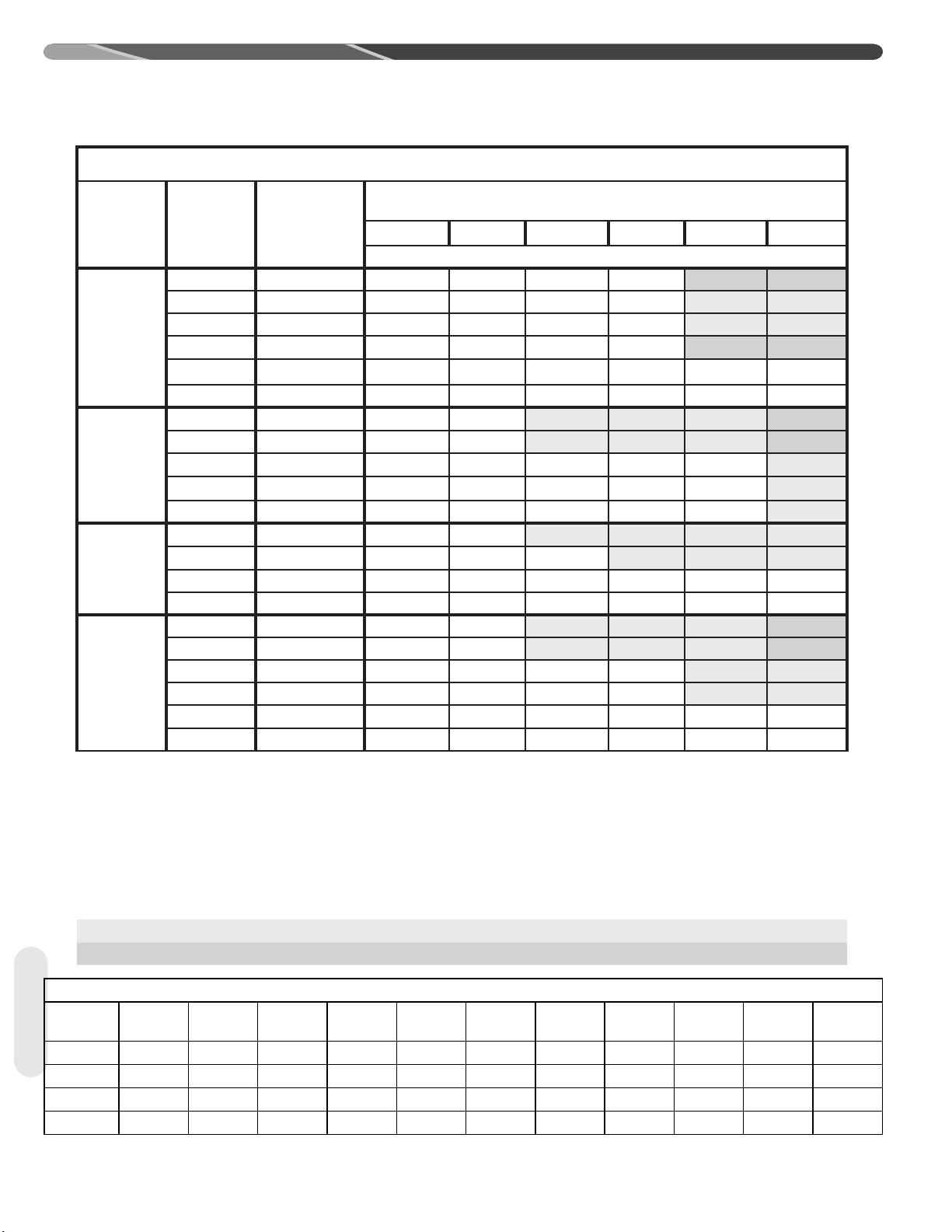
Additional Oil, Oz. 15/16 SEER2 Air Conditoner
Lineset
Length, Ft
2T N/A N/A N/A N/A N/A 1 2 3 5 6 7
3T N/A N/A N/A N/A N/A N/A 1 2 3 5 6
4T N/A N/A N/A N/A N/A N/A N/A N/A N/A N/A N/A
5T N/A N/A N/A N/A N/A N/A N/A N/A N/A N/A N/A
4.5 Line Set Installation
50 60 70 80 90 100 110 120 130 140 150
• If tubing is to be run underground, it must be run in
a sealed watertight chase.
• Use care in routing tubing and do not kink or twist.
Use a good quality tubing bender on the vapor line
to prevent kinking.
• Route the tubing using temporary hangers; then
straighten the tubing and install permanent hangers.
The tubing must be adequately supported.
• Isolate the vapor line from the building structure. If
the vapor line comes in contact with inside walls,
ceiling, or flooring, the vibration of the vapor line
4.5.1 Important Tubing Installation Practices
Observe the following when installing correctly sized
type “L” refrigerant tubing between the outdoor unit and
indoor coil:
• Check Table 2 for the correct vapor line size and
liquid line size.
• If a portion of the liquid line passes through a
very hot area where liquid refrigerant can be
heated to form vapor, insulating the liquid line is
required.
• Use clean, dehydrated, sealed refrigeration-grade
tubing.
• Always keep tubing sealed until tubing is in place and
connections are to be made.
• A high-quality biflow filter drier is included with all
R-410A heat pump units and must be installed in the
liquid line upon unit installation.
• When replacing an R-22 system with an R-410A
system and the line set is not replaced, blow out
the lines with dry nitrogen to remove as much of the
remaining mineral oil as possible. Check for low spots
where oil may be trapped and take measures to drain
the oil from those areas.
in the heating mode will result in noise inside the
structure.
• Blow out the liquid and vapor lines with dry nitrogen
before connecting to the outdoor unit and indoor
coil to remove debris that can plug the expansion
device.
• If tubing has been cut, debur the ends while holding
the tubing in a position to prevent chips from
falling into tubing. Burrs such as those caused by
tubing cutters can affect performance dramatically,
particularly on small diameter liquid lines.
• For best operation, keep tubing run as short as
possible with a minimum number of elbows or bends.
• Locations where the tubing will be exposed to
mechanical damage should be avoided. If it is
necessary to use such locations, the copper tubing
should be protected by a housing to prevent damage.
Tubing
17
Page 18
4.0 INSTALLATION
4.5 Line Set Installation (cont.)
4.5.2 Relative Location of Indoor and Outdoor Units
4.5.2.1 Outdoor Unit Level or Near Level to Indoor Coil Line Set
REFERENCE TABLE 2 FOR
MAXIMUM LENGTH LIMITATIONS
IDEALLY, LINE SET SLOPES AWAY
FROM OUTDOOR UNIT. VERIFY
SUB-COOLING PRIOR TO EXPANSION
DEVICE, INSULATED LIQUID LINE IN
UNCONDITIONED SPACE FOR
LONG LINE APPLICATIONS.
Figure 3
For applications with the outdoor unit and indoor
unit on the same level the following is required:
• Insulated liquid line in unconditioned space only.
• Insulated vapor line full length.
• Vapor line should slope toward the indoor unit.
(Reference Figure 3)
Tubing
INSULATED VAPOR LINE FULL LENGTH
ST-A1219-01-01
• Follow the proper line sizing, maximum linear
and equivalent length, charging requirements,
and oil level adjustments spelled out in this document.
• Verify at least 5°F [2.8°C] sub-cooling at the
indoor unit prior to expansion device.
18
Page 19

4.0 INSTALLATION
4.5.2.2 Outdoor Unit Below Indoor Coil (Long Line Set Applications)
INSULATED VAPOR LINE FULL LENGTH
Figure 4
INSULATE LIQUID LINE
IN UNCONDITIONED
SPACE FOR LONG
LINE APPLICATIONS
INVERTED TRAP
EVEN WITH TOP
OF THE COIL
VERIFY LIQUID SUBCOOLING
PRIOR TO EXPANSION DEVICE
IN THE COOLING MODE.
REFERENCE TABLE 2 FOR
MAXIMUM LENGTH AND
VERTICAL SEPARATION LIMITATIONS
ST-A1219-02-01
For applications with the outdoor unit below the
indoor coil, the following is required:
• Inverted vapor-line trap (Reference Figure 4)
• Insulated liquid line in unconditioned space only.
• Insulated vapor line full length.
• Follow the proper line sizing, maximum linear
and equivalent length, maximum vertical separation, charging requirements, and oil level adjustments spelled out in this document.
• Measure pressure at the liquid line service valve
and prior to expansion device. Verify that the
pressure drop is not greater than 50 PSI [345
kPa].
• For elevations greater that 25’ [8 m] a lower subcooling can be expected.
• Verify there is at least 5ºF [2.8ºC] of liquid subcooling at the indoor coil prior to the expansion
device.
Tubing
19
Page 20

4.0 INSTALLATION
/ŶƐƵůĂƚĞĚǀĂƉŽƌůŝŶĞĨƵůůůĞŶŐƚŚ
4.5.2.3 Outdoor Unit Above Indoor Coil
sĞƌŝĨLJůŝƋƵŝĚƐƵďͲĐŽŽůŝŶŐ
ĂƚŽƵƚĚŽŽƌƵŶŝƚƉƌŝŽƌ
ƚŽĞdžƉĂŶƐŝŽŶĚĞǀŝĐĞ
Figure 5
/ŶƐƵůĂƚĞĚůŝƋƵŝĚůŝŶĞ
ŝŶƵŶĐŽŶĚŝƚŝŽŶĞĚƐƉĂĐĞ
ĨŽƌůŽŶŐůŝŶĞ
ĂƉƉůŝĐĂƚŝŽŶ
ZĞĨĞƌĞŶĐĞdĂďůĞϮĨŽƌ
ŵĂdžŝŵƵŵůĞŶŐƚŚĂŶĚ
ǀĞƌƚŝĐĂůƐĞƉĂƌĂƚŝŽŶ
ůŝŵŝƚĂƚŝŽŶƐ
For applications with the outdoor unit above the
indoor coil the following is required:
• Insulated liquid line in unconditioned space only.
• Follow the proper line sizing, maximum linear and
equivalent length, maximum vertical separation,
charging requirements, and oil level adjustments
spelled out in this document.
Tubing
20
• Insulated vapor line full length.
• Verify at least 5°F [2.8ºC] of liquid subcooling at
the outdoor unit prior to expansion device in the
heating mode.
Page 21

4.5.3 Tubing Connections
Indoor coils have only a holding charge of dry
nitrogen. Keep all tube ends sealed until connections
are to be made.
• Use type “L” copper refrigeration tubing. Braze the
connections with the following alloys:
– Copper to copper, 5% silver minimum
– Copper to steel or brass, 15% silver minimum
• Be certain both refrigerant shutoff valves at the
outdoor unit are closed.
4.0 INSTALLATION
•
Wrap valves with a wet rag or thermal barrier compound
before applying heat.
•
Braze the tubing between the outdoor unit and indoor
coil. Flow dry nitrogen into a pressure port and through
the tubing while brazing, but do not allow pressure inside
tubing which can result in leaks. Once the system is full
of nitrogen, the nitrogen regulator should be turned off to
avoid pressuring the system.
•
Remove the caps and Schrader cores from the pressure
ports to protect seals from heat damage. Both the
Schrader valves and the service valves have seals that
may be damaged by excessive heat.
•
Clean the inside of the fittings and outside of the tubing
with a clean, dry cloth before soldering. Clean out
debris, chips, dirt, etc., that enters tubing or service
valve connections.
• A
fter brazing, use an appropriate heatsink material to
cool the joint.
• Reinstall the Schrader cores into both pressure ports.
• Do not allow the bare vapor line and liquid line
to be in contact with each other. This causes an
undesirable heat transfer resulting in capacity loss
and increased power consumption.
Tubing
21
Page 22

4.0 INSTALLATION
ST-A1226-07-00
4.6 Initial Leak Testing
Indoor coils have only a holding charge of dry
nitrogen. Keep all tube ends sealed until
connections are to be made.
WARNING: Do not use oxygen
to purge lines or pressurize system for leak test.
Oxygen reacts violently with oil, which can cause
an explosion resulting in severe personal injury or
death.
•
Pressurize line set and coil through service
fittings with dry nitrogen to 150 PSIG [1,034 kPa]
(maximum). Close nitrogen tank valve, let system
sit for at least 15 minutes, and check to see if the
pressure has dropped. If the pressure has dropped,
check for leaks at the line set braze joints with
soap bubbles and repair leak as necessary. Repeat
pressure test. If line set and coil hold pressure,
proceed with line set and coil evacuation (see
Sections 4.7 and 4.8 for evacuation and final leak
testing).
temperatures that occur there.
4.7 Evacuation
Evacuation is one of the most important parts of
the entire installation and service procedure. The
life and efficiency of the equipment is dependent
upon the thoroughness exercised by the
serviceman when evacuating air and moisture from
the system.
Air or nitrogen in the system increases condensing
temperature and pressure, resulting in increased
power consumption, erratic operation, and reduced
capacity.
Moisture chemically reacts with the refrigerant
and oil to form corrosive acid which attacks the
compressor motor windings and internal parts and
which can result in compressor failure.
• After the system has been leak-checked and
proven sealed, connect the vacuum pump and
evacuate system to 500 microns and hold 500
microns or less for at least 15 minutes. The
vacuum pump must be connected to both the
high and low sides of the system by connecting
to the two pressure ports. Use the largest size
connections available since restrictive service
connections may lead to false readings because
of pressure drop through the fittings.
Tubing
22
• The vapor line must be insulated for its entire
length to prevent dripping (sweating) and prevent
performance losses. Closed-cell foam insulation
such as Armaflex and Rubatex® are satisfactory
insulations for this purpose. Use 1/2" [12.7 mm]
minimum insulation thickness. Additional
insulation may be required for long runs. The
liquid line must be insulated in any unconditioned
space when long line sets are used and anytime
the liquid line is run through an attic due to hot
Page 23

4.0 INSTALLATION
4.9.1 EcoNet™ Communications
The EcoNet
Series heat pumps and air conditioners are specifically
designed to be matched with and EcoNetTM enabled
air-handler or gas furnace and the EcoNetTM Control
Center. While they are also designed to be controlled
by a conventional 24VAC 2-stage thermostat, many
features and benefits are lost.
TM
enabled (-)A15AZ/(-)P16AZ/(-)A16AZ
• After adequate evacuation, open both service
valves by removing both brass service valve caps
with an adjustable wrench. Insert a 3/16" [5 mm]
or 5/16" [8 mm] hex wrench into the stem and turn
counterclockwise until the wrench stops.
• If not already connected from evacuation process,
gauges must be connected at this point to check and
adjust charge.
IMPORTANT: Compressors should
never be used to evacuate the air conditioning
system because internal electrical arcing in near
vacuum conditions may result in a damaged or failed
compressor. Never run a scroll compressor while the
system is in a vacuum or compressor failure will occur.
4.8 Final Leak Testing
After the unit has been properly evacuated and service
valves opened, a halogen leak detector should be
used to detect leaks in the system. All joints and piping
within the outdoor unit, indoor coil, and interconnecting
tubing should be checked for leaks. If a leak is
detected, the refrigerant should be recovered before
repairing the leak. The Clean Air Act prohibits releasing
refrigerant into the atmosphere.
4.9 Control Wiring
WARNING: Turn off electric power
at the fuse box or service panel before making any
electrical connections. Also, the ground connection
must be completed before making line voltage
connections. Failure to do so can result in electrical
shock, severe personal injury, or death.
4.9.2 EcoNet™ Control Center
Installation
The EcoNet
to 5 feet [1.2 to 1.5 m] above the floor on an inside
wall of the living room or a hallway that has good
air circulation from the other rooms being controlled
by the Control Center. It is essential that there
be free air circulation at the location of the same
average temperature as other rooms being controlled.
Movement of air should not be obstructed by furniture,
doors, draperies, etc. The Control Center should not
be mounted where it will be affected by drafts, hot or
cold water pipes or air ducts in walls, radiant heat from
fireplace, lamps, the sun, T.V. or an outside wall. See
instructions packaged with Control Center for detailed
mounting and installation instructions.
TM
Control Center should be mounted 4
4.9.3 EcoNet™ Communication Wiring
Connections
The four 18 AWG low-voltage control wires must be
installed from the EcoNet™ Control Center to the
indoor unit and from the indoor unit to the outdoor unit.
The wire length between the Control Center and indoor
unit should not be greater than 100 feet [30.5 m].
The wire length between the indoor unit and outdoor
unit should not be greater than 125 feet [38.1 m].
Running low-voltage wires in conduit with line voltage
power wires is not recommended. Low-voltage wiring
must be connected to the low voltage terminal block on
the Universal Outdoor Control. The terminal block can
be unplugged from the control board to facilitate wiring.
An EcoNet™ communicating heat pump system
consists of these matched components:
• EcoNet™ communicating outdoor unit.
• EcoNet™ communicating air handler or EcoNet™
communicating furnace.
• EcoNet™ Control Center.
Wiring
23
Page 24

4.0 INSTALLATION
Indoor
Unit
E1
E2
C
R
EcoNet™
Control Center
Outdoor
Unit
E1
E2
C
R
E1
E2
C
R
4.9 Control Wiring (cont.)
Wiring
IMPORTANT: The EcoNet™ control
system requires continuous 18 AWG thermostat
wire. Do not use phone cord to connect indoor
and outdoor units. This will damage the
controls.
The EcoNet™ control system requires four (4)
control wires for unit operation:
• R 24 VAC
• C 24 VAC common
• Data wire E1 Communications
• Data wire E2 Communications
The EcoNet™ enabled air handler or furnace is
equipped with a 24-volt, 40 or 50 VA transformer
for proper system operation. See the wiring
diagram below for low voltage wiring connections.
4.9.4 Conventional 24VAC
Thermostat Control Wiring
Connections
The (-)A15AZ(-)P16AZ/(-)A16AZ series of outdoor
units allow the installer to use a conventional
2-stage thermostat for limited unit operation.
IMPORTANT: The preferred method
of unit installation and operation is by the EcoNet™
Communicating System which allows access to
the fault history of the system. This diagnostic
information is not available at the thermostat when
the (-)A15AZ/(-)P16AZ/(-)A16AZ unit is using a
conventional 2-stage thermostat.
Thermostat control wiring requires a minimum of
six (6) wires for proper heatpump operation and
four (5) wires for proper AC operation:
R – 24 VAC (AC/HP)
C – 24 VAC common (AC/HP)
Y1 – Speed Command 1 (AC/HP)
Y2 – Speed Command 2 (AC/HP)
B – Heat pump operation (HP)
W – Supplemental Heat During Defrost Cycle
(AC/HP)
These wires need to be connected to each device
(Control Center, indoor air handler or furnace, and
outdoor unit).
Once all devices are connected, apply the line
voltage to the indoor and outdoor units.
When all devices are powered, the EcoNet™
Control Center should detect the indoor and
outdoor units within 45 seconds.
Once the system is powered and all components
are communicating with each other, the airflow
settings will be automatically configured in the airhandler or furnace.
All adjustments for indoor airflow are made at the
EcoNet™ Control Center from this point. Items
that can be changed are airflow trim adjustment,
on-demand dehumidification, cooling and heating
airflow and electric heat airflow. The Control
Center also has a wide range of fault and history
information. To access any of the control center
menus press the settings, status, or service icons
at the bottom of the touch screen. Refer to the
air handler or furnace installation manual and
the EcoNet™ Control Center installation manual
for further details on setting up the system and
available adjustment options.
24
The following figures show the typical control wiring
diagrams with (-)A15AZ/(-)A16AZ/(-)P16AZ heat
pumps using a conventional two-stage 24VAC
thermostat. Cooling and heating airflow levels will
need to be adjusted for homeowner comfort once
the system is operational.
WIRE COLOR CODE
BK – BLACK GY – GRAY W – WHITE
BR – BROWN O – ORANGE Y – YELLOW
BL – BLUE PR – PURPLE
G – GREEN R – RED
Page 25

4.9 Control Wiring (cont.)
Field-Installed
Heat Pump
Indoor
Unit
24 VAC 2 - Stage Thermostat HP
R
C
Y1
Y2
B
W
E1
E2
R
C
Y1
Y2
B
W
R
C
E1
E2
ST-A1324-02
ST-A1324-03
Field-Installed
A16 Air
Conditioner
Indoor
Unit
24 VAC 2 - Stage Thermostat AC
R
C
Y1
Y2
W
E1
E2
R
C
Y1
Y2
W
R
C
E1
E2
4.0 INSTALLATION
TYPICAL 2-STAGE THERMOSTAT:
(-)P16 HEAT PUMP WITH AIR-HANDLER
USING A THERMOSTAT WITH DEHUMIDIFICATION
TYPICAL 2-STAGE THERMOSTAT:
AC WITH AIR-HANDLER
To ensure this, measure “R” to earth or chassis
ground on the indoor unit and make sure it measures
24VAC while “C” to chassis/earth ground is 0VAC.
On the new outdoor transformer, with the transformer
connected to the ODU thermostat terminal block,
ensure that the low voltage lead connected to “R” on
the thermostat terminal block of the unit measures
24VAC to earth/chassis ground while “C” on the same
terminal block measures 0VAC to earth or chassis
ground
WARNING: Never route low voltage
(eg 24VAC thermostat) wiring in the same conduit or
whip as line voltage (eg 120VAC, 240VAC and etc).
Wiring
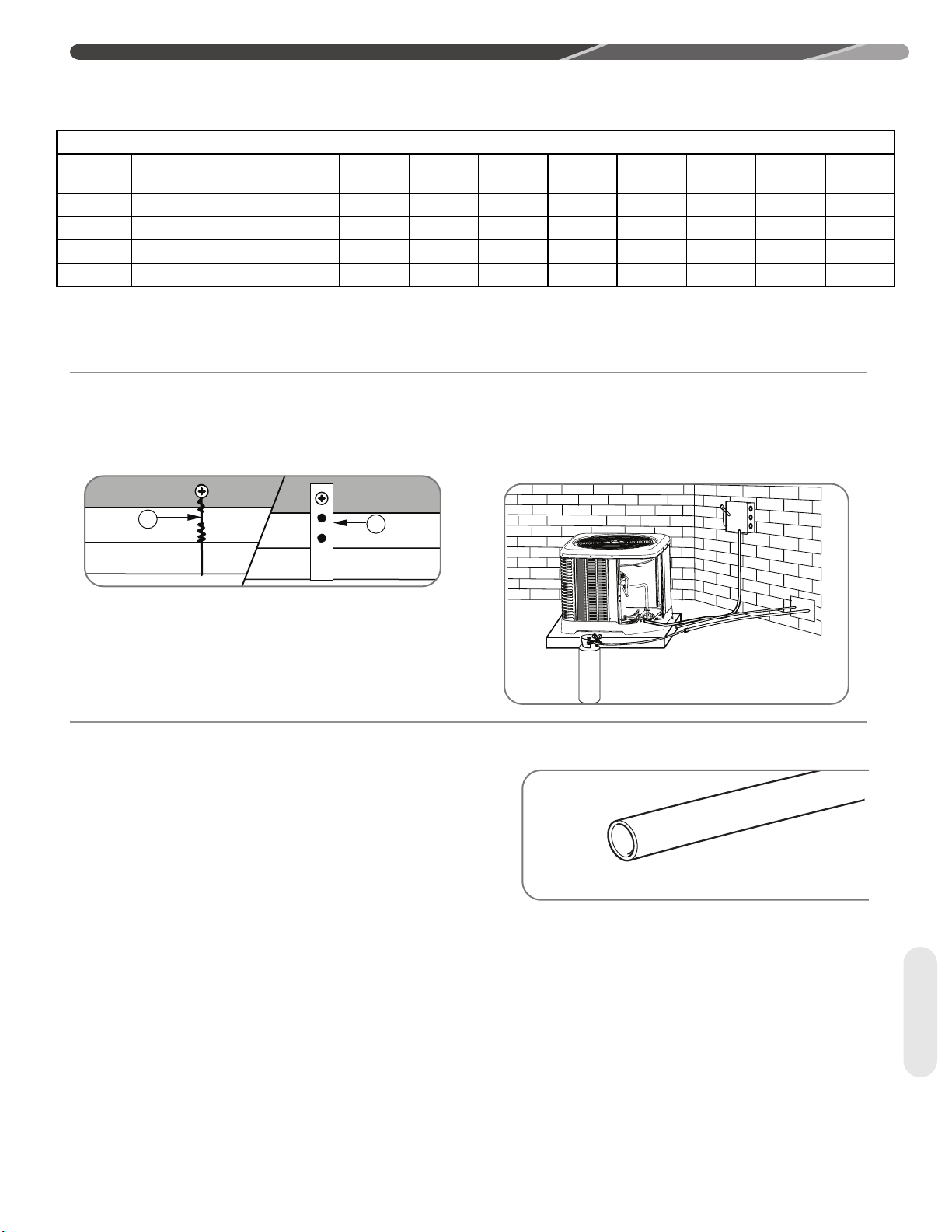
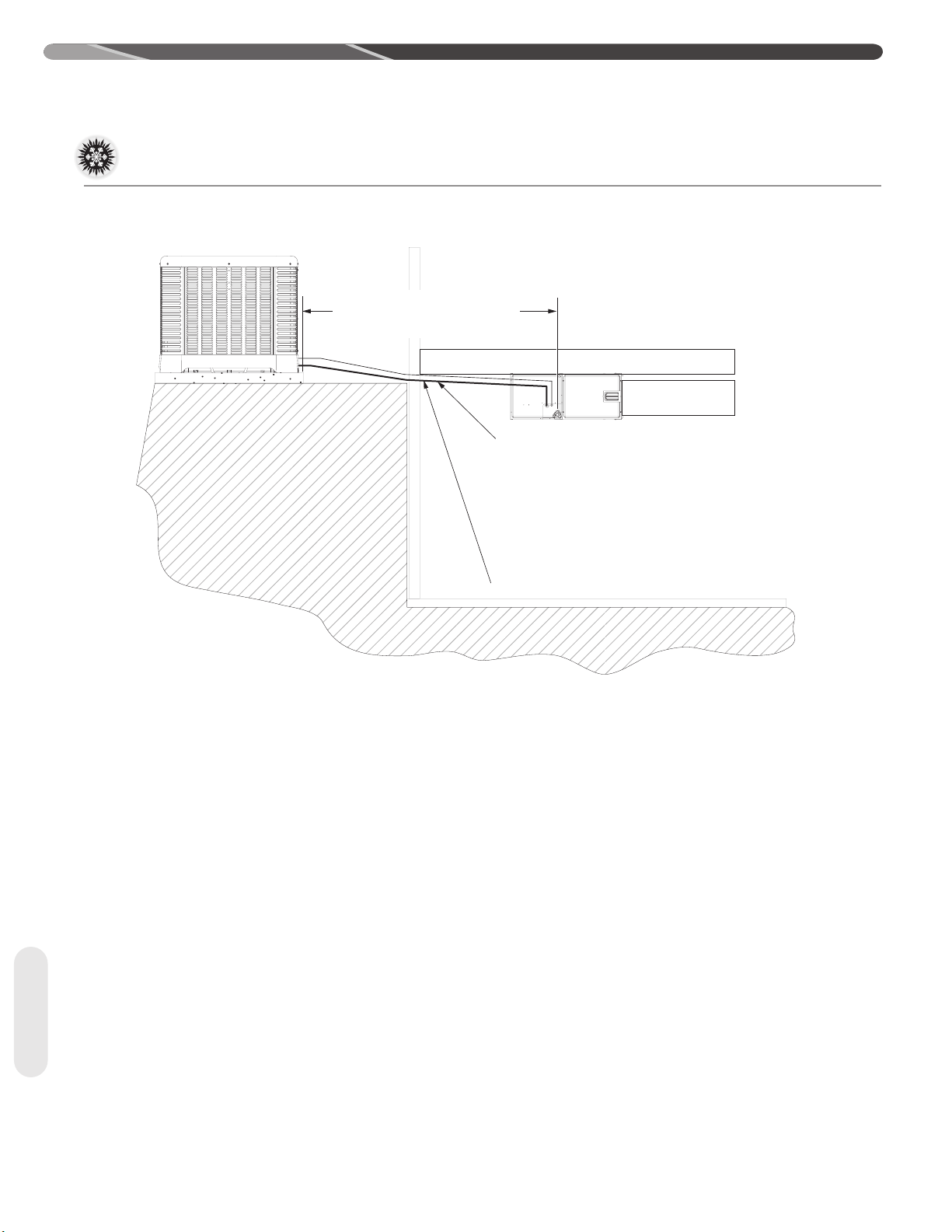
4.9.5 For Installations With Only
2 Thermostat Wires Between The
Indoor And Outdoor Units.
Sourcing the following components and materials,
use the provided wiring diagram to create an external
24VAC power supply to unit in the case that only two
thermostat wires can be practically supplied from the
indoor unit to the outdoor unit
Do not mount the new enclosure with the transformer
to the outdoor unit. The enclosure with transformer
must be mounted to the exterior wall of the home or
structure or to a separate post or stand
Note that it is critical that the additional transformer is
properly phased with the original transformer on the
indoor unit.
Install the fuse in the “R” circuit from the new
transformer inside the new NEMA/IP enclosure
(inthe “R” wire before exiting the enclosure) with the
transformer by crimping the 1/4 “ QC terminals to the
wire and connecting those terminals directly to the
legs of the fuse as shown in the photo below.
It is important that proper electrical power is available
at the heat pump power terminal block. The acceptable
operating voltage range is shown below.
25
Page 26

4.0 INSTALLATION
4.9 Control Wiring (cont.)
Parts/Materials:
1. Minimum NEMA 3R or IP-65 rated, watertight
electrical enclosure with integrated key, screw-down
lid or padlock feature to prevent accidental access.
Interior dimensions should be at least 2.5” x 3.5” x
3.5”. (note: enclosures with Knock-out (KO) are
preferred for simplification of installation).
Same as, or similar to Grainger Item 3A909
2. A minimum 40VA (40W) (minimum), 240VAC to
24VAC (alternate 208VAC to 24VAC for 208VAC
applications) Transformer
Same as, or similar to Rheem part number
46-101905-01
3. Watertight conduit or electrical whips with
watertight fittings/clamps (size and length as
necessary) on each end. Two must be supplied;
one for 240VAC wires and another for 24VAC
wires.
Warning: Never route low voltage (eg 24VAC
thermostat) wiring in the same conduit or whip as line
voltage (eg 120VAC, 240VAC and etc).
4. 18GA wire with 2/64” Insulation rated for 600V
(minimum), preferred colors;
FOR ECONECT INSTALLATIONS WITH
G
G
CONDUIT OR WHIP
O
BK
O/R
CAP
O
PR
ROUTE ALLL
WIRING IN
WATER-TIGHT
ONLY 2 THERMOSTAT WIRES
BK
G
O (BK)
BK (W)
OUTDOOR UNIT CONTROL BOX
GND
240
OR
208
VAC
ELECTRICAL
DISCONNECT
L1
Y
BK/Y
5 WIRES
TO COMM
MODBUS P1 ON VSODU
J130
H
P
S
J03-01
1 (m)
Y
KO
L2
KO
FERRITERING
COII
RELAY
J03-02
INVERTER
2 (c)
BK/Y
DRIVE
3 (s)
Y
BK/Y
BK R Y BK/Y
P302
Y
J120
TB
L2
BK
R
Y
J110
1
2
3
O
4
GND KO
L1
KO= KNOCKOUT
CONTACTOR
L1 T1
L2 T2
A1 A2
R
GROUND
LUG
G
BR (R)
5 WIRES
TO COMM
MODBUS
J130 ON
INVERTER
DRIVE
Brown (24VAC Common),
Red (24VAC SEC),
Black (240AC, L1),
Orange (240VAC L2)
(all wire lengths will depend on installation)
5. 14GA wire with 2/64” Insulation rated for 600V
(minimum), preferred colors:
Green (ground) to disconnect or control box of
outdoor unit
(wire length will depend on installation)
6. Appropriate mounting screws or bolts to mount
transformer inside of NEMA/IP electrical enclosure.
7. 3Amp ATC Style Fuse Same as, or similar to
Grainger Item 2FCY5
8. ¼” 18GA insulated quick-connect (QC) terminals,
QTY = 6 Same as, or Similar to Grainger Item
21DH01
9. 14GA Ring Terminal, Qty = 1
Same as, or similar to Grainger Item 3VRU9
BK
PR
P1
L1
L2
PRV
COM
GND
HPS
INDOOR
UNIT
E1
E2
FOR 240 VAC,
USE “240” TERM.
FOR 208 VAC,
USE “208” TERM.
R
V
S
KO
R
UNIVERSAL
OUTDOOR
CONTROLLER
R
E1E2RCY2YBWU
V
S
Y
L2
KO
IN SOME CONDUIT
(UODC)
LOW VOLTAGE T-STAT
WIRING TO T-STAT AND
INDOOR SECTION
TRANSFORMER
240 208 61
NOTE: DO NOT
ROUTE LINE
VOLTAGE LOW
VOLTAGE WIRE
KO
KO
CR
L1
GND
U2
ATC FUSE
J17
J15
J16
P9
P2
P6
OAT
P7
P3
P4
P5
P
10
NEW ELECTRICAL
ENCLOSURE (MINIMUM
NEMA 3
IP65)
NOTE: CAN
NOT BE MOUNTED
ON THE
OUTDOOR
UNIT
ROUTE GROUND
WIRE TO
TRANSFORMER
MOUNTING
FOOT USING
14GA RING
TERMINAL
CONTROL BOX
FERRITERING
MAIN CABINET
BK
PR
R
PRESSURE
RELIEF
VALVE
DISCHARGE
TEMP. SENSOR
COIL
TEMP. SENSOR
SUCTION
TEMP. SENSOR
LIQUID
TEMP. SENSOR
SUCTION
TRANSDUCER
LIQUID
TRANSDUCER
RVS
HPC
PSC (BLDC) FAN
C
M
COMP
S
MOTOR
26
ST-A1342-01
Page 27

4.0 INSTALLATION
Nameplate
Operating Voltage Range at
4.10 Power Wiring
it is important that proper electrical power is available
at the heat pump power terminal block. The acceptable
operating voltage range is shown below.
VOLTAGE RANGES (60 HZ)
Voltage
208/230
Install a branch circuit disconnect within sight of the
unit and of adequate size to handle the minimum circuit
ampacity (MCA) current (see “Electrical Data” in Section
3.2).
Field wiring must comply with the National Electric Code
(C.E.C. in Canada) and any applicable local code.
Power wiring must be run in a rain-tight conduit. Conduit
must be attached to the hole in the bottom of the control
box.
Connect power wiring to line-voltage lugs on the
terminal block located in the outdoor heat pump unit
electrical box. (See wiring diagram attached to unit
access panel.)
Maximum Load Conditions
197–253
4.11 Grounding
WARNING: The unit must be
permanently grounded. Failure to do so can cause
electrical shock resulting in severe personal injury or
death.
A ground lug is provided near the line-voltage power
entrance for a ground wire.
Check all electrical connections, including factory wiring
within the unit and make sure all connections are tight.
DO NOT connect aluminum field wire to the line
voltage terminal block.
27
Page 28

5.0 SYSTEM START-UP AND REFRIGERANT CHARGING
5.1 System Start-Up Overview
Once the system hardware and wiring has been
properly installed, the next step is to start the system
up, verify indoor air-flow, and adjust the refrigerant
charge. To assure optimum comfort, efficiency,
and reliability, it is extremely important to follow the
procedures in this section to assure the indoor air-flow
and refrigerant charge are correct.
5.2 Initial Power-Up
and EcoNet™ Communication
Verication
Wiring
After all installation steps have been completed, apply
electrical power to the indoor and outdoor units. The
EcoNetTM Control Center or thermostat should be
switched to the off position initially. Within 45 seconds
of power being applied, the EcoNetTM Control Center
should detect the indoor and outdoor units.
IMPORTANT: It is recommended to wait
at least 12 hours after electrical power is applied to
the outdoor unit before starting the compressor to
assure any liquid refrigerant inside the compressor has
been driven out by the compressor stator heat.
5.3 EcoNet™ Control Center SetUp
Follow the set-up instructions included with the
EcoNetTM Control Center prior to starting system.
Cooling dehumidification must be disabled for indoor
air-flow verification and refrigerant charging. The
indoor air-flow trim adjustment should be set to 0%
for indoor air-flow verification, but should be adjusted
prior to refrigerant charging should the application
require an adjustment to the indoor air-flow.
5.4 Initial System
Start-Up
Using the EcoNet™ Control Center service menu
(See Section 5.5 below) or using the thermostat (See
Section 5.6 below), put the system into the charging
mode which will force it to operate at 100% capacity
and indoor air-ow which is necessary for accurate
indoor air-ow verication and refrigerant charging.
Check to make sure "On-Demand Dehumidication"
is turned off in the EcoNet™ Control Center (or
on the air-handler or gas furnace control board for
conventional 24VAC control applications).
Start-Up
28
Page 29

5.0 SYSTEM START-UP AND REFRIGERANT CHARGING
5.5 Entering Charge Mode Using
EcoNet™ Control Center Service
Menu
1. Set the "Mode" to the "OFF" position.
2. Select "SERVICE" on the EcoNet™ Control Center
screen.
3. Select "ODU Checkout". If the next screen displays
a flashing "Lock-Out" message, there will be up to
a 5 minute delay before it is possible to continue.
4. Once the flashing lock-out message disappears,
touch OFF on the screen displayed to the right of
"Var Speed ODU Test".
5. Touch the "UP" arrow repeatedly until the "Heat
Charge" or "Cool Charge" menu item is displayed
depending on which mode the system is to be
charged in.
6. Touch "Start Test".
7. System will now operate at 100% of capacity and
indoor air-flow to allow proper indoor air-flow verification and refrigerant charging until the Charge
Mode is manually ended. There may be a delay
before the system actually starts. If the system
doesn't start, cycle power to both the indoor and
outdoor units and repeat steps 1-6.
8. Note: When charging in the heating mode, the system will initiate a defrost cycle every 34 minutes if
the coil temperature is below 35ºF [1.7ºC] to assure
the coil stays frost free during the charging process.
Allow the system to complete the defrost cycle and
stabilize for at least 10 minutes before attempting to
evaluate the charge level.
9. To end Charge Mode, touch the "UP" arrow repeatedly until "OFF" is displayed on the screen and
then touch "Stop Test". Then touch the left arrow
on the screen to return to the main screen.
10. If the indoor blower continues to run continuously
after exiting the Charge Mode, cycle the power to
the air-handler or furnace.
5.6 Entering Charge Mode
When Using a Universal
Outdoor Control
1. Set the thermostat to the cool or heat mode
depending on which mode the system is to be
charged in.
2. Adjust the set point several degrees below
(cool mode) or above (heat mode) the room
temperature to assure the thermostat is calling
for operation and will continue to do so throughout
the charging process.
3. When the charging process is complete, adjust
the temperature set-point to the desired level.
Start-Up
29
Page 30

5.0 SYSTEM START-UP AND REFRIGERANT CHARGING
5.7 Indoor Air-Flow Verication
Correct indoor air-flow and proper supply air
distribution is critical to system comfort, efficiency
and reliability. Excessive indoor air-flow results in
elevated humidity levels in the cooling mode and
excessive air noise. Low indoor air-flow reduces
system capacity and can result in coil icing and
compressor failure in the cooling mode and can
cause nuisance high pressure switch tripping and
increases power consumption in the heating mode.
Fortunately, when the (-)A15AZ/(-)P16AZ/(-)A16AZ
outdoor unit are matched to the correct air-handler
or furnace/coil combination and are controlled by
the communication EcoNetTM Control Center, the
indoor air-flow is automatically controlled to the
proper level based on the model data stored in the
UODC. When the indoor blower is operating, the
EcoNetTM Control Center will display the indoor
air-flow in the Service Menu of the control. The
approximate indoor air-flow is also displayed in
100 CFM [47 l/s] increments by a flashing LED on
Outdoor Unit
Model No.
(-)P16AZ24/(-)A16AZ24/(-)A15AZ24 750 750
(-)P16AZ36/(-)A16AZ36/(-)A15AZ36 1125 1125
(-)P16AZ48/(-)A16AZ48/(-)A15AZ48 1450 1450
(-)P16AZ60/(-)A16AZ60/(-)A15AZ60 1800 1800
Displayed Indoor CFM
the air-handler or furnace control board while the
blower is operating (one flash per 100 CFM [47
l/s]) for installations where a conventional 24VAC
thermostat is used.
Once the system is operating in the Charging
Mode, confirm the indoor air-flow is close to those
values in the table below. If the displayed indoor
air-flow is not reasonably close to the value in the
table, confirm cooling dehumidification is disabled,
the indoor air-flow trim adjustment is set to 0%,
and verify the model numbers of the indoor and
outdoor units are an approved combination by the
manufacturer. Once the indoor air-flow is verified,
the indoor air-flow trim adjustment may be changed
to suit the installation and should be done prior to
final charge adjustment.
NOTICE: AHRI rated indoor air-flow may differ
slightly from values in the table below.
NOTE: All indoor air-ow trims must be adjusted
using the bluetooth contractor's app.
Displayed Indoor CFM
Cooling Mode
Heating Mode
Start-Up
30
5.8 Refrigerant Charging
The refrigerant charge for all systems should be
checked against the Charging Chart located inside
the access panel cover.
WARNING:
compressor shell is hot. Touching the compressor top
may result in serious personal injury.
CAUTION:
approximately 60% higher (1.6 times) than R-22
pressures. Use appropriate care when using this
refrigerant. Failure to exercise care may result in
equipment damage or personal injury.
Charge for all systems should be checked against the
Charging Chart inside the access panel cover.
The top of the scroll
R-410A pressures are
IMPORTANT: Do not operate the
compressor without charge in the system.
Addition of R-410A will raise high-side pressures
(liquid and discharge).
NOTICE: System maintenance is to be
performed by a qualified and certified technician.
The optimum refrigerant charge for any outdoor unit
matched with an indoor coil/air handler is affected
by the application. Therefore, charging data has
been developed to assist the field technician in
optimizing the charge for all mounting configurations
(UF – Upflow, DF – Downflow, LH – Left-Hand
Discharge, and RH – Right-Hand Discharge). Refer
to the charging chart inside the access panel cover
on the unit and choose the appropriate column for
the specific application being installed or serviced.
New installations utilizing either an RCF indoor coil
installed on a gas furnace, RH3VZ or an RHMVZ
series air handler in the downflow or horizontal
right-hand discharge may require removal of some
refrigerant since the factory charge could result in an
overcharge condition for short line length applications.
The following method is used for charging systems in
the cooling and heating mode. All steps listed should
be performed to ensure proper charge has been set.
For measuring pressures, the service valve port on
the liquid valve (small valve) and the true service port
located between the two service valves are to be
used.
Page 31

5.0 SYSTEM START-UP AND REFRIGERANT CHARGING
5.8.1 Measurement Device Set-Up
1. With an R-410A gauge set, attach the high-pressure
hose to the access fitting on the liquid line (small)
service valve at the OD unit.
2.
Attach the low-pressure hose to the exterior suction
port located between the two service valves that is
connected to the suction tube between the reversing
valve and compressor
3. Attach a temperature probe within 6" [15.2 cm]
of the outside of the unit on the copper liquid line
(small line). For more accurate measurements,
clean the copper line prior to measurement and
use a calibrated clamp-on temperature probe or an
insulated surface thermocouple.
.
5.8.2 Preliminary Charging by
Weight
NOTICE:
the linear length of the refrigerant line set.
For a new installation, evacuation of inter-connecting
tubing and indoor coil is adequate; otherwise,
evacuate the entire system. Use the factory charge
shown in “Electrical and Physical Data” in Section 3.2
of these instructions or on the unit data plate. Note
that the charge value includes charge required for 15
ft. [4.6 m] of standard-size liquid line without a filter
drier.
Calculate actual charge required with the actual
installed liquid line size and length using:
1/4" [6.4 mm] O.D. = .3 oz./ft. [28.3 g/m]
5/16" [7.9 mm] O.D. = .4 oz./ft. [37.7 g/m]
3/8" [9.5 mm] O.D. = .6 oz./ft. [56.7 g/m]
1/2" [12.7 mm] O.D. = 1.2 oz./ft. [113.3 g/m]
Add 6 oz. [170 g] for field-installed filter drier.
Charge Adjustment = (Line Set (oz./ft.) x Total
Length) – Factory Charge for Line Set
Example: A three ton heat pump unit with factory
installed 3/8” liquid service valve requires 75 ft. of line
set with a liquid line diameter of 1/2”.
Factory Charge for Line Set = 15 ft. × .6 oz. = 9 oz.
Charge Adjustment = (1.2 oz. × 75 ft.) – 9 oz. =
+ 81 oz.
With an accurate scale (+/– 1 oz. [28.3 g]) or
volumetric charging device, adjust the refrigerant
charge based on the actual line set length. If the entire
system has been evacuated, add the total calculated
charge.
Adjust the system charge by weight for
IMPORTANT: Charging by weight is
not always accurate since the application can affect
the optimum refrigerant charge. Charging by weight
is considered a starting point ONLY. Always check
the charge by using the Charging Chart and adjust as
necessary. CHARGING BY LIQUID SUBCOOLING
PER THE SYSTEM CHARGING CHART MUST BE
USED FOR FINAL CHARGE ADJUSTMENT.
IMPORTANT: R-410A is a blended
refrigerant of R-32 and R-125 (50/50). These two
refrigerants have different saturation curves and
therefore change state at different pressures and
temperatures. If charge is added to the system in the
vapor state, it is possible to have a disproportionate
amount of each part of the R-410A blend which will
cause unstable and inefficient operation. Therefore, it
is critical to add R-410A in the liquid form only!
5.8.3 Preliminary Charging by
Pressures (Optional)
1. Following airflow verification and charge weigh-in,
run the unit for a minimum of 15 minutes prior to
noting pressures and temperatures.
IMPORTANT: Indoor conditions as
measured at the indoor coil must be within 2°F [1.1°C]
of comfort conditions per the homeowner's preference.
NOTICE:
or below this range, run the system to bring the
temperature down or run the electric heat/furnace to bring
the temperature up to within this range.
2. Note the Outdoor Dry Bulb Temperature, ODDB° =
_____°F [°C]. Unit charging is recommended under
the following outdoor conditions ONLY:
Cooling Mode ONLY: 55°F [12.8°C] outdoor dry
bulb and above
Heating Mode ONLY: Between 40°F [4.4°C] and
60°F [15.6°C] outdoor dry bulb
3. Locate and note the design pressures. The correct
liquid and vapor pressures are found at the
intersection of the installed system and the outdoor
ambient temperature on the Charging Chart located
inside the access panel cover.
Liquid Pressure: = ______psig [kPa]; Vapor
Pressure = ______psig [kPa]
NOTICE:
are for preliminary charge check ONLY. These pressure
values are typical, but may vary due to application.
Evaporator load (indoor coil in cooling mode/outdoor
coil in heating mode) will cause pressures to deviate.
The values listed are for the correct matched indoor coil
If the indoor temperature is above
The refrigerant pressures provided
31
Start-Up
Page 32

5.0 SYSTEM START-UP AND REFRIGERANT CHARGING
ONLY!
4. If the measured liquid pressure is below the
listed requirement for the given outdoor and
indoor conditions, add charge. If the measured
liquid pressure is above the listed requirement
for the given outdoor and indoor conditions,
remove charge.
5.8.4 Final Charging by Liquid
Subcooling
1. After preliminary charging by weight or
pressures, find the design subcooling value.
The correct subcooling value is found at the
intersection of the installed system and the
outdoor ambient temperature on the Charging
Chart located inside the access panel cover.
SC° from Charging Chart = _____°F [°C].
IMPORTANT: Indoor conditions
as measured at the indoor coil are required to
be within 2ºF (1.1ºC) of comfort conditions as
preferred by the homeowner and must have
operated for at least 15 minutes prior to final
charge adjustment. Unit charging is recommended
under the following outdoor conditions ONLY:
Cooling Mode: 55°F [12.8°C] outdoor dry bulb
and above
Heating Mode: Between 40°F [4.4°C] and 60°F
[15.6°C] outdoor dry bulb
NOTICE: Systems should not be charged
below 40°F [4.4°C] outdoor temperature.
NOTICE: If the indoor temperature is
above or below the recommended range, run the
system to bring the temperature down or run the
electric heat/furnace to bring the temperature up.
2. Note the measured Liquid Pressure, Liq Press =
______psig [kPa], as measured from the liquid
(small) service valve. Use the Temperature
Pressure Chart below to note the corresponding
Start-Up
5.8.5 R-410A Temperature Pressure Chart
SATUR ATION
TEMP ºF [ºC]
-150 [-101] – -30 [-34] 17.9 [123.4] 35 [2] 107.5 [741.2] 10 0 [38] 317.4 [2188.4]
-140 [ -96] – -25 [-32] 22.0 [151.7] 40 [4] 118.5 [817.0] 105 [41] 340.6 [2348.4]
-130 [-90] – -20 [-29] 26.4 [182.0] 45 [ 7] 13 0.2 [89 7.7] 110 [ 43] 365.1 [2517.3]
-120 [ -84] – -15 [- 26 ] 31.3 [215.8] 50 [10] 142.7 [983.9] 115 [ 46] 390.9 [2695.2]
-110 [-79] – -10 [-23] 36 .5 [251.7 ] 55 [13] 156.0 [1075.6] 120 [4 9] 418.0 [2882.0]
-100 [-7 3] – -5 [ -21] 42.2 [291.0] 60 [16] 170.1 [1172. 8] 125 [52] 446.5 [3078.5]
-90 [-68] – 0 [-18 ] 48.4 [333.7] 65 [18] 185.1 [1276.2] 130 [5 4] 476.5 [3285.4]
-80 [- 62] – 5 [ -15] 5 5.1 [38 0.0 ] 70 [21] 2 01.0 [1385 .8] 135 [ 57] 508.0 [3502.5]
-70 [-57 ] – 10 [-12 ] 62.4 [430.2] 75 [24] 217.8 [1501.7] 140 [60] 541.2 [37 31.4]
-6 0 [-51] 0.4 [2.8] 15 [-9] 70. 2 [484.0] 80 [27] 235.6 [1624.4] 145 [63] 576.0 [3971.4]
-50 [- 46] 5.1 [35.2] 20 [-7] 78 .5 [5 41.2] 85 [29] 254.5 [1754.7] 150 [6 6] 612.8 [4225.1]
-40 [-40] 10.9 [75.2] 25 [-4] 8 7.5 [ 60 3.3] 90 [32] 2 74. 3 [1891. 2]
-35 [-37] 14 .2 [ 97.9] 30 [-1] 97.2 [670.2] 95 [35] 295.3 [2036.0]
32
R-410A
PSIG [kPa]
SATUR ATION
TEMP ºF [ºC]
R-410A
PSIG [kPa]
saturation temperature for R-410A at the
measured liquid pressure.
Liquid Saturation Temperature, SAT°= _____°F
[°C].
3. Note the liquid line temperature, Liq° = _____°F
[°C], as measured from a temperature probe
located within 6" [15.2 cm] outside of the
unit on the copper liquid line (small line). It is
recommended to use a calibrated clamp-on
temperature probe or an insulated surface
thermocouple.
4.
Subtract the liquid line temperature from the
saturation temperature to calculate subcooling.
SAT°_____°F
SC°_____°F
5.
Adjust charge to obtain the specified subcooling
[°C]
- Liq°_____°F
[°C]
[°C]
=
value. If the measured subcooling level is below
the listed requirement for the given outdoor
temperature, add charge. If the measured
subcooling level is above the listed requirement
for the given outdoor temperature, remove
charge.
5.9 Completing Installation
• Disconnect the hoses from the pressure ports.
Replace the pressure port caps and tighten
adequately to seal caps. DO NOT overtighten.
• Replace the service valve top caps finger-tight
and then tighten with a wrench to adequately seal
caps. DO NOT overtighten.
• Replace control box cover and service panel and
install screws to secure panels.
• Restore power to unit at disconnect if required.
• Exit Charging Mode and configure EcoNet™
Control Center or thermostat per the thermostat
installation instructions and set to desired mode
and temperature.
SATUR ATION
TEMP ºF [ºC]
R-410A
PSIG [kPa]
SATUR ATION
TEMP ºF [ºC]
R-410A
PSIG [kPa]
Page 33

6.0 NORMAL SEQUENCE OF OPERATION
The following sections provide details on how the
(-)A15AZ/(-)P16AZ/(-)A16AZ outdoor systems are
designed to operate under normal conditions.
Under abnormal conditions, Active Compressor and
Inverter Protection features built into the controls
may alter how the system operates to protect the
compressor and inverter from damage. The sequence
of operation is based on the system being set up
for EcoNetTM communications using an EcoNetTM
enabled air-handler or gas furnace and an EcoNetTM
Control Center. A section is provided at the end
that describes how the system will operate if a
conventional 24VAC 2-stage thermostat is used.
NOTE: The use of a conventional 24VAC
thermostat eliminates many of the advanced
operating and diagnostic features the customer
has paid for and is strongly discouraged.
6.1 Cooling Mode
The (-)A15AZ/(-)P16AZ/(-)A16AZ unit will have
variable capacity from 45% to 65%. A compressor
demand above 65% capacity shall switch the inverter
operation to line voltage. This type of hybrid operation
shall either take place in a fully communicating
system or when connected to a communicating
indoor unit and a non-communicating thermostat.
In communicating mode, the control center shall
send the compressor demand and shall decide when
the inverter runs at line voltage or at variable speed
capacity.
Note: In legacy mode the outdoor control shall
determine the compressor speed.
The percentage of capacity required is based on the
difference between the temperature set-point and the
room temperature measured at the Control Center.
One second after the compressor starts, the UODC
will direct the variable speed outdoor motor to operate
at the appropriate speed to deliver the necessary
outdoor air-flow for that capacity percentage. Upon
a call for cooling/heating, the EcoNetTM Control
Center accesses the indoor air-flow parameters found
in the model data residing in the UODC and directs
the EcoNetTM enabled air-handler or gas furnace
control board to deliver an appropriate indoor air-flow
level based on the capacity percentage required at
that point in time. The EcoNetTM air-handler or gas
furnace control board will then direct the variable
speed indoor blower motor to start and operate at
the requested cooling/heating air-flow level. As the
building load changes throughout the call for cooling/
heating operation, the compressor speed, outdoor
fan speed, and indoor air-flow level will respond by
ramping up or down as required to meet the building
load exactly rather than simply cycling on and off as
conventional systems do. When the call for cooling/
heating has ended, the EcoNetTM Control Center will
direct the outdoor and indoor units to shut down. The
compressor and outdoor fan motor will ramp down
to zero RPM and the indoor blower motor will ramp
down to the minimum air-flow level for 30-45 seconds
to extract the residual heating from the cold indoor
coil before it stops.
Note: Anytime the compressor goes to line
operation, the unit shall stay there until the
heating/cooling satisfies the thermostat demand
6.2 On-Demand Cooling
Dehumidication
The EcoNetTM Control Center can be configured for
On-Demand Dehumidification. This feature allows
the system to automatically increase the level of
dehumidification in the cooling mode by decreasing
the indoor air-flow by 15% when the indoor relative
humidity measured at the Control Center rises above
the set-point. Once the relative humidity drops to or
below the set-point, the indoor air-flow level returns to
normal.
6.3 Low Ambient Cooling Mode
In some installations, a requirement exists for cooling
a controlled air space when the outdoor ambient
is below the normal range for cooling such as a
computer room or other enclosed areas where a large
heat load exists that must be kept cool. Low ambient
cooling is a special cooling mode that allows the unit
to provide cooling when the outdoor temperature is
below low ambient temperature. When necessary,
the outdoor fan shall be cycled off to maintain liquid
pressure in the system. Operation below low ambient
temperature requires special interpretation of the state
of the suction pressure. If the outdoor air temperature
is less than the low ambient temperature, a flag shall
be set and the low ambient cooling algorithm shall
run. If the outdoor temperature rises one degree
above the low ambient temperature, the low ambient
cooling algorithm shall turn off and the flag shall be
reset
Note: This mode shall not be active if any sensor
error code is active.
6.4 Supplemental Electric
Heat in
Heating Mode
If the building load should exceed the heating
capacity in extreme outdoor conditions, the EcoNetTM
Control Center or 24 VAC 2-stage thermostat will
direct the RH3VZ or RHMVZ air-handler to energize
supplemental electric heat as required to meet the
building load. The indoor air-flow will be forced to
operate at the maximum level for the system. For
13kW heaters and higher, the supplemental electric
33
Operation
Page 34

6.0 NORMAL SEQUENCE OF OPERATION
heat will be energized in two stages as required.
The compressor and outdoor fan will continue to
operate at maximum capacity while supplemental
electric heat is energized.
6.5 Dual Fuel Applications
–
Heating Mode
If the building load should exceed the heat pump
heating capacity in extreme outdoor conditions,
the EcoNetTM Control Center will direct the outdoor
unit to shut down and heating responsibility will be
transferred to the gas furnace. An outdoor ambient
temperature can be set in the EcoNetTM Control
Center to direct the system to automatically switch
to gas heat when the outdoor ambient temperature
drops below that set-point. If the EcoNetTM
Control Center is set to the EMERGENCY HEAT
(Furnace Only) mode, heating responsibility will be
transferred to the gas furnace.
6.6 Demand Defrost
Defrosting of the outdoor coil in the heating mode
is controlled by the Universal Outdoor Control
(UODC). (-)P16AZ heat pumps utilizes “demand
defrost” that initiates a defrost cycle only when
frosting is detected on the outdoor coil during
heating operation. The UODC continuously
monitors the Outdoor Ambient Temperature
Thermistor (OAT) and Outdoor Coil Temperature
Thermistor to determine when a defrost cycle is
required. The following sequence is followed for
defrost cycles.
• Defrost Initiation: A defrost cycle is initiated
when the following conditions are met.
1. The outdoor coil temperature is below 35°F
[1.7°C].
2. The compressor has operated for at least
34 minutes with the outdoor coil
temperature below 35°F [1.7°C].
3. The UODC determines a defrost cycle
is required based on the OAT and EVAPIN
temperatures.
on line voltage then the unit will remain
on line voltage until the defrost cycle is
complete.
4. The indoor air-handler or gas furnace
is directed to supply supplemental heat
to prevent cold air from being discharged
from the supply registers during the
defrost cycle.
5. The compressor speed is ramped to the
pre-determined defrost speed for the
duration of the defrost cycle.
• Defrost Termination: The defrost cycle will
continue until the coil temperature has reached
the termination temperature or 14 minutes
have elapsed, whichever comes first. The
factory default termination temperature is 60°F
[15.6°C]. When the coil temperature reaches
the termination temperature or 14 minutes have
elapsed, the following action is taken.
1. The compressor speed is ramped to the
reversing valve switching speed for 30
seconds before the reversing valve is
energized.
2. The reversing valve will be energized,
switching it back to the heating position.
3. The outdoor fan motor is energized.
4. Auxiliary heat is de-energized.
5. The compressor speed will ramp to a pre determined oil circulation speed for 6
minutes.
6. The system returns to normal heating
operation as directed by the EcoNetTM
Control Center.
NOTE: Should the outdoor ambient
temperature thermistor fail, the UODC
will initiate a defrost every 34 minutes of
operation when the coil temperature is below
35°F.
If the above conditions are met, the following
action will be taken.
1. The compressor speed is ramped to the
predetermined reversing valve switching
speed for 30 seconds before the reversing
valve is de-energized.
2. The reversing valve is de-energized which
will cause it to shift to the cooling position.
Note: If the demand for defrost is initiated
while on the drive the unit will remain on the
drive until the defrost cycle is complete. If
the demand for the defrost is initiated while
34
Page 35

6.0 NORMAL SEQUENCE OF OPERATION
Žŝů
6.7 Sequence of Operation for
Off
On
Off
On
Off
Off
On
On
dĞŵƉĞƌĂƚƵƌĞ
ĂƚĞĨƌŽƐƚ
dĞƌŵŝŶĂƚŝŽŶ
º
60
F [15.6ºC]
50ºF [10ºC]
º
F [4.4ºC]
40
º
70
F [21.1ºC]
Conventional 2-Stage 24VAC
Thermostat Controls
The (-)A15AZ/(-)P16AZ/(-)A16AZ unit will have
variable capacity from 45% to 65%. A compressor demand above 65% capacity shall switch the
inverter operation to line voltage. This type of hybrid
operation shall either take place when connected to
a communicating indoor unit and a non-communicating thermostat.
In legacy mode, the outdoor control shall determine
the compressor speed.
The difference between the temperature set-point
and the room temperature measured at the 24VAC
2-stage thermostat will determine whether the system gets a cooling or heating call. Upon a cooling/
heating call, the UODC will command the air-handler
or gas furnace control board to deliver an appropriate indoor air-flow level based on the capacity using
the parameters stored internally to the UODC. One
second after the compressor starts, the UODC will
direct the variable speed outdoor motor to operate at
the appropriate speed to deliver the necessary outdoor air-flow for that capacity based on the parameters stored in the UODC. As the building load
changes throughout the call for cooling/heating operation, the compressor speed, outdoor fan speed,
and indoor air-flow level will respond by ramping up
or down as required to meet the building load exactly
rather than simply cycling on and off as conventional
systems do. When the call for cool ing/heating has
ended, the call from the 2-stage thermostat will be
removed and the UODC will direct the outdoor and
indoor units to shut down. The compressor and outdoor fan motor will ramp down to zero RPM and the
indoor blower motor will ramp down to the minimum
air-flow level for 30-45 seconds to extract the residual heating from the cold indoor coil before it stops.
Operation
Note: Anytime the compressor goes to line operation, the unit shall stay there until the heating/
cooling satisfies the thermostat demand
35
Page 36

7.0 COMPONENTS & CONTROLS
7.1 EcoNet™ Universal Outdoor Control (UODC)
7.1.1 Board Features and
Connections
(-)A15AZ/(-)P16AZ/(-)A16AZ outdoor units are
equipped with a Universal Outdoor Control (UODC)
that interfaces with the inverter, EcoNetTM Control
Center, and EcoNetTM enabled air-handler or gas
furnace using the EcoNet
protocol. The UODC provides a low voltage
terminal block for control wiring and connections
for various sensors, controls, outdoor fan motor
and inverter. If an alert or alarm occurs the Econet
Control Center will display the active faults as
well as fault history. If used with the conventional
24 VAC 2-stage thermostat then these faults can
be found using the Bluetooth Contractor's App.
Buttons are provided to initiate and terminate
various test modes. A plug-in memory card
provides model specific information (model data)
necessary for proper
The following is a list of features on the UODC and
location of each.
1. Bluetooth
2. Discharge Temp
TM
serial communication
3. EXV
4. OAT
5. COIL/OST
6. OLT/CPT
7. Suction Pressure Tranducer
8. Liquid Pressure Tranducer
9. Reversing Valve
10. HPS
11. Common
12. Pressure Relief Valve
13. ModBus
14. SW1 and SW2
15. Power Supply LED
16. Fault Code LED
17. CPU Status LED
18. Heating Status LED
19. Cooling Status LED
20. Bluetooth LED
CAUTION: UNIT MAY START
SUDDENLY AND WITHOUT WARNING.
Components
16
1
20
19
18
14
17
2
13
7.1.2 Factory Superheat Setting
34
15
5
6
7
12 11
8
9
10
ST-A1324-04
The UODC is pre-programmed with the optimum superheat setting of 6º for each outdoor unit.
36
Page 37

7.0 COMPONENTS & CONTROLS
7.2 Power Inverter Compressor
Control
(-)A15AZ/(-)P16AZ/(-)A16AZ outdoor units are
equipped with a power inverter that varies the compressor speed to match the changing capacity needs
of the conditioned space. The inverter interfaces
with the Universal Outdoor Control (UODC) which
communicates the level of system capacity that is
required to the inverter based on input from the
EcoNetTM Control Center or conventional 24VAC
2-stage thermostat. The inverter converts incoming
single phase power to simulated variable frequency
3-phase power that is connected to the 3-phase compressor motor. Each of the four (-)P20 models has
a unique inverter specifically designed and qualified
for that specific model to provide reliable operation
under the most extreme conditions. Each inverter
is programmed to monitor compressor power consumption, motor torque, input current, input voltage,
1
compressor discharge pressure, and compressor
discharge temperature. When the inverter identifies
a condition that could potentially result in compressor
or inverter damage, it automatically reduces the compressor speed until a more reliable operating condition is obtained or shuts the compressor completely
off if necessary. Once safe operating conditions
are attained, the inverter will gradually increase the
compressor speed in an attempt to meet the capacity
demand as long as the operating conditions remain
within the safe operating range of the compressor
and inverter.
1. RS485 Communication
2. Input Power
3. Drive Output
4. OD Fan Motor
2
Components
3
4
37
Page 38

8.0 ACTIVE SYSTEM PROTECTION FEATURES
The controls found in the (-)A15AZ/(-)P16AZ/
(-)A16AZ outdoor units are designed to prevent
the system from operating in under conditions
that could be harmful to the compressor and
inverter. The Universal Outdoor Control (UODC)
and Power Inverter continuously monitor multiple
sensors, current, and voltage and will modify the
compressor speed or completely shut the system
down to protect the compressor and/or inverter
if harmful operating conditions are sensed. This
process is called Active System Protection.
Sections 8.1 – 8.14 give a brief description of the
different forms of protection that are provided.
Refer to the Econet help pages on the Rheem
website for further troubleshooting and diagnostics.
8.1 Minimum Run Timer
A minimum run time of 5 minutes is maintained by
the VSODC to minimize short cycling which can be
harmful to the compressor.
8.2 Oil Return Cycle
When the system has been operating at
significantly reduced capacity for an extended
period of time, the Universal Outdoor Control
(UODC) will signal the Inverter to speed the
compressor up to 70% capacity to help bring any
oil that has accumulated in the indoor coil and
refrigerant lines back to the compressor sump.
8.3 High Discharge
Temperature
The Power Inverter continuously monitors the
Discharge Line Thermistor input to protect the
compressor should the discharge temperature
reach an unsafe level. If the discharge line
temperature rises to 235°F [113ºC], the Inverter
will reduce the compressor RPM incrementally
until the temperature drops to 200°F [93ºC]. After
the discharge temperature reaches 200°F [93ºC],
the Inverter will gradually increase the compressor
RPM until the compressor returns to normal
speed based on the capacity demand. Should the
discharge temperature rise to 235°F [113ºC] again,
the Inverter to repeat the speed reduction cycle to
maintain a temperature below 235°F [113ºC].
8.4 High Discharge Pressure
The High Pressure Control (HPC) limits the
compressor discharge pressure to a safe level
to prevent damage to the compressor. When
the HPC contacts open at 610 PSIG [4206 kPa],
the compressor will proceed to shut down and
restart per the sequence shown below. If the HPC
contacts open three (3) times during the same
call for operation, the EcoNetTM Control Center
will display a High Refrigerant Pressure Lockout
fault on the screen. A manual reset is required
for the UODC to exit the compressor lock-out
mode and clear the fault. This is accomplished
by disconnecting the electrical power to both the
indoor and outdoor units for 1 minute and then
reconnecting power.
NOTE: If the system experiences a high
refrigerant pressure lock-out, the system
should be evaluated to determine the cause
for the high pressure condition and corrective
action taken to eliminate the cause. Possible
causes include excessive refrigerant charge,
a failed indoor blower motor, dirty return air
filter, or a dirty indoor coil (heating mode) or
excessive refrigerant charge, a failed outdoor
motor, or dirty outdoor coil (cooling mode).
8.5 Low Suction Pressure
/
Loss of Charge
The Universal Outdoor Control (UODC)
continuously monitors the Suction Pressure
Transducer input and will protect the compressor
from damage by shutting it down when the suction
pressure drops below 50 PSIG [345 kPa] in the
cooling mode and below 15 PSIG [103 kPa] in the
heating mode. A low pressure condition can result
from inadequate indoor air-flow, low refrigerant
charge or a restriction in the refrigerant circuit.
The UODC will allow the compressor to restart if
the suction pressure rises to 95 PSIG [655 kPa]
in the cooling mode and 40 PSIG [276 kPa] in the
heating mode. A low refrigerant pressure fault will
be ignored for the first 90 seconds of compressor
operation and during the entire defrost cycle to
eliminate nuisance faults.
System Protection
38
Page 39

8.0 ACTIVE SYSTEM PROTECTION FEATURES
If there are 3 low pressure faults in the same call for
cooling or during 120 minutes of continuous heating
operation, the UODC will lock the compressor out
and the EcoNetTM Control Center will display a Low
Refrigerant Pressure Lockout fault on the screen. If
the outdoor ambient is below -10°F [-23°C] in the
heating mode when the lockout occurs, the control
will automatically reset when the outdoor ambient
rises to -10°F [-23°C]. If the outdoor ambient is
above -10°F [-23°C], a manual reset is required
for the VSODU to exit the compressor lock-out
mode and clear the fault. This is accomplished by
disconnecting the electrical power to both the indoor
and outdoor units for 1 minute and then reconnecting
power.
NOTE: If the system experiences a low
refrigerant pressure lock-out, the system should
be evaluated to determine the cause for the low
pressure condition and corrective action taken
to eliminate the cause. Possible causes include
low refrigerant charge, failed indoor blower
motor, dirty return air filter, or a dirty indoor coil
in the cooling mode or low refrigerant charge, a
failed outdoor motor, or a dirty outdoor coil in the
heating mode.
8.6 Compressor Shut-Down
Sequence for High or Low
Refrigerant Pressure Fault
1. The compressor is commanded to operate at
zero (0) RPM for a minimum of 5 minutes.
2. The outdoor fan motor will continue to operate
during the 5 minute compressor off delay.
3. The UODC and EcoNetTM Control Center will
display the applicable fault code.
4. If after 5 minutes cooling or heating demand
persists and the pressure has reached reset
conditions, normal system operation will resume
and the fault codes will be cleared from the
UODC and EcoNetTM Control Center displays.
5. If after 5 minutes cooling or heating demand
persists and the pressure has not reached
reset conditions, the outdoor fan motor will be
shut down. Once the pressure reaches reset
conditions after the 5 minute delay, normal
system operation will resume.
8.7 Overcurrent and Current
Imbalance
If the compressor current exceeds an acceptable
level for the compressor or inverter, the inverter
will reduce the compressor speed to allow the
current to return to an acceptable level. If there is a
current imbalance between the compressor 3-phase
windings, the inverter will shut the compressor down
for 5 minutes and will lock the compressor out if there
are 3 faults within a single call for operation.
8.8 Compressor Operation
Outside Envelope
If the inverter detects that the compressor motor
torque exceeds an acceptable level for the
compressor, the inverter will reduce the compressor
speed to keep the torque at an acceptable level.
8.9 Over and Under Voltage
If the supply voltage or internal DC voltage is not
within an acceptable operating range, the inverter will
shut the compressor off until the voltage returns to an
acceptable level.
8.10 Inverter Over Temperature
If the internal inverter temperature sensors detect
excessive temperatures within the inverter, the
inverter will reduce the speed of the compressor or
shut the compressor down until the temperatures
drop to an acceptable level. The compressor will be
locked out if there are 3 faults within a single call for
operation.
8.11 Controls and
Communication Malfunction
If the controls senses a malfunction within the control
system or communications or if system model data is
not available, the controls will act to shut the system
down to prevent the system from operating at a
condition that could harm components.
System Protection
39
Page 40

8.0 ACTIVE SYSTEM PROTECTION FEATURES
8.12 Sensor Failure Default Operation
If the controls sense an externally connected sensor
has failed, the system will enter a fail safe operating
mode and will continue to condition the space until
the sensor can be replaced. A fault code will be
FAILED COMPONENT FUNCTION DEFAULT OPERATION
Low Ambient Cooling No Low Ambient function
Outdoor Sensor (OAT)
Coil Sensor
One minute fan off delay on COO L mode No delay functions if failure is open or short. Continue function for a ther mistor range error.
PWM Shif t above 104°F [40°C] Shift will not occur
Defrost Initiate and Terminate Defrost will occur at each time inter val, but will terminate after 5 minutes
Defrost Defrost will be initiated based on coil temperature and time
Low Ambient Cooling No function
displayed on the EcoNetTM Control Center and
Universal Outdoor Control identifying which sensor
has failed. See the table below for the default
operation for a sensor failure.
8.13 Exiting Active Protection Lock-Out Mode
Exiting an Active Protection Lock-Out mode can
be accomplished by disconnecting electrical
power to both the indoor and outdoor units for 1
minute and then restoring power. Keep in mind
there was a reason for the lock-out, so the fault
code on the Universal Outdoor Control (UODC) or
EcoNetTM Control Center should be read to assist
with diagnosing the root cause of the lock-out and
corrective action should be taken to prevent the
system from repeating the lock-out.
System Protection
40
Page 41

9.0 DIAGNOSTICS & TROUBLESHOOTING
Advanced operating status and diagnostic information is available through the EcoNetTM Control Center that
greatly enhances the ability to quickly and accurately diagnose system faults. For further assistance for
troubleshooting a system please see the Bluetooth Contractor's App or the Econect Help Pages at myrheem.
com.
EcoNet Fault Code Response Action
A001_O Model Data Conguration Error Lockout while active, short cycle to restart.
A002_O Compressor Model Data Error Lockout while active, short cycle to restart.
A003_O Fan Model Data Error Lockout while active, short cycle to restart.
A093_O Model Data Restore Failure Lockout while active, short cycle to restart.
A100_O Communications Lost with Indoor Unit Lockout while active, short cycle to restart.
A906_O Inverter Fault - AC Input Overvoltage Lockout while active, short cycle to restart.
A907_O Inverter Fault - AC Input Undervoltage Lockout while active, short cycle to restart.
A910_O Inverter Fault - Lost Rotor Position 3-strikes to permanent lockout
A912_O Inverter Fault - Self-Check Fault Lockout while active, short cycle to restart.
A915_O Inverter Fault - Comm Fault Lockout while active, short cycle to restart.
A920_O Inverter Fault - PFC Desaturation 3-strikes to permanent lockout
A924_O Inverter Fault - Board Temp 3-strikes to permanent lockout
A925_O Inverter Fault - Comp. Model Unknown Lockout while active, short cycle to restart.
A926_O Inverter Fault - HP Sensor Not Congured Lockout while active, short cycle to restart.
A927_O Inverter Fault - Drive Conguration Lockout while active, short cycle to restart.
A928_O Locked Out - See History Faults Permanent lockout
A929_O 240V Missing or Inverter Comm Failure Lockout while active, short cycle to restart.
A950_O Conguration Data Restore Failure Lockout while active, short cycle to restart.
A953_O Coil Temp Thermistor Failure Algorithms default
A954_O Suction Temp Thermistor Failure Algorithms default
A956_O Suction Pressure Sensor Failure Algorithms default
A957_O Low Refrigerant Pressure 4-hour lockout
A958_O High Refrigerant Pressure 4-hour lockout
A960_O Compressor Locked Rotor - Lockout Permanent lockout
A970_O Inverter/Compressor Mismatch Permanent lockout
A975_O Contactor Stuck On Lockout while active, short cycle to restart.
A979_O Compressor Over/Under Speed 3-strikes to permanent lockout
A980_O Fan Self Check Fault Lockout while active, short cycle to restart.
A987_O Compressor Loss of Phase 3-strikes to permanent lockout
A988_O Compressor Control Lost 3-strikes to permanent lockout
A989_O Charge Relay Open 3-strikes to permanent lockout
A990_O Compressor U-Phase Over Current 3-strikes to permanent lockout
A991_O Compressor V-Phase Over Current 3-strikes to permanent lockout
A992_O Compressor W-Phase Over Current 3-strikes to permanent lockout
A993_O Compressor Module Over Current 3-strikes to permanent lockout
A994_O Compressor Parameter Fault Lockout while active, short cycle to restart.
A998_O Fan Motor Parameter Fault Lockout while active, short cycle to restart.
T901_O Inverter Fault - Comp. Overcurrent 3-strikes to permanent lockout
T902_O Inverter - Envelope Protection Follow req.M1HPC-SR-79
Diagnostics
41
Page 42

9.0 DIAGNOSTICS & TROUBLESHOOTING
Advanced operating status and diagnostic information is available through the EcoNetTM Control Center that
greatly enhances the ability to quickly and accurately diagnose system faults. For further assistance for
troubleshooting a system please see the Bluetooth Contractor's App or the Econect Help Pages at myrheem.
com.
T903_O Inverter Fault - PFC Overcurrent 3-strikes to permanent lockout
T904_O Inverter Fault - DC Bus Overvoltage 3-strikes to 30 minute lockout
T905_O Inverter Fault - DC Bus Undervoltage Lockout while active, short cycle to restart.
T908_O Inverter Fault - PIM Over-temp 3-strikes to permanent lockout
T909_O Inverter Fault - PFC Over-temp 3-strikes to permanent lockout
T911_O Inverter Fault - Current Imbalance 3-strikes to permanent lockout
T914_O Inverter Fault - DC Voltage Low 3-strikes to permanent lockout
T916_O Inverter Fault - Discharge Line Temp 3-strikes to permanent lockout
T917_O Inverter Fault - PIM Temp 3-strikes to permanent lockout
T918_O Inverter Fault - PFC Temp 3-strikes to permanent lockout
T922_O Inverter Fault - PIM Temp Foldback 3-strikes to permanent lockout
T923_O Inverter Fault - High Refrig Pressure 3-strikes to 4-hour lockout
T931_O Fan Fault Phase Over Current 3-strikes to permanent lockout
T932_O Fan Fault Phase Current Imbalance 3-strikes to permanent lockout
T933_O Fan Fault Motor Over/Under Speed 3-strikes to permanent lockout
T934_O Fan Fault U-Phase Over Current 3-strikes to permanent lockout
T935_O Fan Fault V-Phase Over Current 3-strikes to permanent lockout
T936_O Fan Fault W-Phase Over Current 3-strikes to permanent lockout
T937_O Fan Fault Module Over Current 3-strikes to permanent lockout
T938_O Fan Fault Loss of Phase 3-strikes to permanent lockout
T939_O Fan Fault Loss of Control 3-strikes to permanent lockout
T940_O Fan Fault Module Over Temperature 3-strikes to permanent lockout
T941_O Fan Fault Start Up Fault 3-strikes to permanent lockout
T942_O Fan Fault Module Temp High 3-strikes to permanent lockout
T952_O Outside Temp Thermistor Failure Algorithms default
T955_O Compressor Temp Thermistor Failure Algorithms default
T957_O Low Refrigerant Pressure 3-strikes to 4-hour lockout
T960_O Compressor Locked Rotor 6-strikes to permanent lockout
T961_O Discharge Temp Thermistor Failure Algorithms default
T971_O Compressor Lube Protection Follow req.M1HPC-SR-80
T972_O Compressor Discharge Temp High Follow req.M1HPC-SR-81
T974_O Line Current Trip 3-strikes to permanent lockout
T981_O Fan Overcurrent Trip 3-strikes to permanent lockout
T982_O Fan Overvoltage Trip 3-strikes to permanent lockout
T983_O Fan Undervoltage Fault 3-strikes to permanent lockout
T984_O Fan Locked Rotor Fault 3-strikes to permanent lockout
T986_O High Refrigerant Pressure Envelope 3-strikes to permanent lockout
T995_O IPM Overcurrent Trip 3-strikes to permanent lockout
T996_O Low Side Overcurrent Trip 3-strikes to permanent lockout
T997_O High Side Overcurrent Trip 3-strikes to permanent lockout
42
Page 43

9.0 DIAGNOSTICS & TROUBLESHOOTING
9.1 Checking Transducers & Temperature Sensors
TRANSDUCERS:
Checking transducers for accuracy can be tricky.
A technician will be required to do some voltage
reading and math to validate the transducer is
functioning properly. Additionally, comparing it to a
reliable source can also be a challenge. Unless the
gauges have been calibrated recently, the question
remains, which one is right?
Knowing where to take the measurement, and
getting solid reading is crucial. Measurements
are done in the 0-5 volt DC range. One confusing
point may be that we will take our measurements
OUT and IN to the control, which are reversed
when we talk formulas because we want the IN
and OUT of the transducer. For instance, 5VDC out
of the control board, translates to 5VDC into the
transducer. And the lower variable voltage output
from the transducer will be the input to the control
board.
The transducer is not removed or disconnected
to make these checks. The technician's meter
leads need to be the smaller needle type, or actual
needles can be used to gain access to the points of
measurements.
Formulas for calculating gauge pressure are shown
below.
SUCTION LINE TRANSDUCER:
PSIG = 375 * (VDC out / VDC in) - 8.1
LIQUID LINE TRANSDUCER:
PSIG = 812.5 * (VDC out / VDC in) - 51.85
IMPORTANT: Do the division inside
the parenthesis first, muliplication second, and
subtraction last.
SUCTION LINE TRANSDUCER:
VDC out = 2.4
VDC in = 5.1
So...
PSIG = 375 * (2.4 / 5.1) - 8.1
PSIG = 375 * (0.47) - 8.1
PSIG = 176.25 - 8.1
PSIG = 138.75
LIQUID LINE TRANSDUCER:
VDC out = 3.4
VDC in = 5.1
So...
PSIG = 812.50 * (3.4 / 5.1) - 51.85
PSIG = 812.50 * (0.667) - 51.85
PSIG = 541.67 - 51.85
PSIG = 460.40
The pressures are best measured when the system
is off since they will be the most stable.
The indoor transducer may be removed so the
pressure can be checked with gauges at the actual
port the transducer is connected to. Pressures for
outdoor transducers can be checked at the outdoor
unit service ports with gauges since they are close
enough in proximity to the transducers.
With the system powered, use the smaller meter
tips to measure the voltage at the back of the
transducer harness where it plugs into the control
board. Voltage In will be measured from the Red and
Black wires. (Red is +, Black is -). This should be
very close to 5VDC, but may vary by a few 1/10ths.
Voltage Out will be measured from Green to Black.
(Green is the variable +, Black remains -).
Diagnostics
43
Page 44

9.0 DIAGNOSTICS & TROUBLESHOOTING
9.1 Checking Transducers & Temperature Sensors (cont.)
TEMPERATURE SENSORS:
All the temperature sensors/thermistors used in
the equipment use the same scale of 10,000 Ohms
at 77ºF (25ºC). This means, a sensor exposed to
77ºF will show a resistance of 10,000 Ohms +/1%. As the temperature decreases, the resistance
increases. Alternatively, as the temperature
increases, the resistance decreases.
Measurements will be made with the sensor
disconnected from the control board. Again,
Diagnostics
comparing the results must be done against a
calibrated tester.
A glass of water, mixed completely with ice
chips and given several minutes to settle should
measure 32 to 32.4ºF. [0 - 0.2 ºC]
Tem p F° Ohms Te mp F ° Ohms Temp F° Ohms Tem p F ° Ohms
0 85,378 33 31,738 66 13,138 99 5,9 61
1 82,710 34 30,855 67 12, 8 11 100 5,827
2 8 0,13 5 35 30,000 68 12,493 101 5,697
3 77,6 4 9 36 29,171 69 12,18 4 102 5,570
4 75, 249 37 28,376 70 11, 8 8 3 103 5,446
5 72,931 38 27, 5 8 9 71 11,591 104 5,326
6 70,693 39 26,834 72 11,3 07 105 5,208
7 6 8,531 40 2 6,10 3 73 11,0 3 1 106 5,094
8 66,442 41 25,394 74 10,762 107 4,982
9 6 4, 475 42 24,706 75 10,501 10 8 4,873
10 62,475 43 24,039 76 10,247 109 4,767
11 60,592 44 23,393 77 10,000 110 4,663
12 58,771 45 22,766 78 9,760 111 4,562
13 5 7, 012 46 2 2 ,158 79 9,526 112 4,464
14 55 , 311 47 21,568 80 9,298 113 4,368
15 53,667 48 20,996 81 9,077 114 4 ,274
16 52,077 49 20,4 41 82 8,862 11 5 4,1 8 3
17 50,540 50 19,902 83 8, 651 116 4,094
18 49,054 51 19,379 84 8,448 117 4,007
19 47, 6 1 6 52 18,872 85 8,250 118 3,922
20 46,225 53 18,379 86 8,056 119 3,839
21 44,880 54 17, 9 0 2 87 7, 86 8 12 0 3,758
22 43,578 55 17, 4 3 8 88 7,6 8 5 121 3,679
23 42,318 56 16,9 87 89 7, 5 0 7 12 2 3,602
24 41,0 9 9 57 16,550 90 7,333 123 3,527
25 39,920 58 16,12 5 91 7,1 6 4 124 3,453
26 38,778 59 15 ,713 92 7,000 125 3,382
27 37,672 60 15, 312 93 6,839 126 3,312
28 36,602 61 14,9 23 94 6,683 12 7 3,243
29 35,566 62 14,5 45 95 6,531 128 3 ,17 7
30 34,563 63 14 ,17 8 96 6,383 12 9 3 ,112
31 33,591 64 13,822 97 6,238 13 0 3,048
32 32,650 65 13,475 98 6,098
Apply resistance measurements to the chart found
below and compare to the control.
32º will have a resistance +/- 1% of 32,650 Ohms.
In the event Celsius is being used, the Fahrenheit
temperature will need to be converted.
ºC = (ºF - 32) * 5 / 9
Example using 82ºF
ºC = (82 - 32) * 5 / 9
ºC = (50) * 5 / 9
ºC = 250 / 9
ºC = 27.8
44
Page 45

9.0 DIAGNOSTICS & TROUBLESHOOTING
9.2 General Troubleshooting Guide
WARNING:
Disconnect all power to unit before servicing. Contactor may break only one side.
Failure to shut off power can cause electrical shock resulting in personal injury or death.
SYMPTOM POSSIBLE CAUSE REMEDY
Unit will not run • Power off or loose electrical connection
• Thermostat set too high or low.
• Unit in active compressor protection
• lockout mode
• Blown fuses/tripped breaker
• Transformer defective
• High-pressure control lock-out
• Low-pressure control lock-out
• Miswiring of communications (communication
light on continuously)
• Defective control board
Outdoor fan runs,
compressor doesn't
Insufcient cooling • Improperly sized unit
Compressor short
cycles
Registers sweat • Low indoor airow • Increase speed of blower or reduce restriction.
High head, low vapor
pressures
High head, high
or normal vapor
pressure – Cooling
mode
Low head, high vapor
pressures
Low vapor, cool
compressor, iced
indoor coil
High vapor pressure • Excessive load
Fluctuating head and
vapor pressures
Gurgle or pulsing
noise at expansion
device or liquid line
• Loose connection
• Communication cable disconnected or failed
• Compressor stuck, grounded or open motor
winding, open internal overload.
• Low-voltage condition
• Improper indoor airow
• Incorrect refrigerant charge
• Air, noncondensibles, or moisture in system
• Restricted Refrigerant Circuit
• Incorrect voltage
• Improperly sized unit
• Refrigerant undercharge or overcharge
• (LPC or HPC Cycling)
• Restriction in liquid line, expansion device, or
lter drier
• Stuck TXV
• Dirty outdoor coil
• Refrigerant overcharge
• Outdoor fan not running
• Air or noncondensibles in system
• Reversing Valve leaking by
• Bad compressor
• Low indoor airow
• Operating below 55°F outdoors
• Moisture in system
• Low ambient cooling not operating (coil or
ambient thermistor failure)
• Defective compressor
• TXV hunting
• Air or noncondensibles in system
• Air or noncondensibles in system
• Undercharge long line application
• Check for correct voltage at line voltage connections in
condensing unit.
• Reset – Power cycle high and low voltage to outdoor
• unit.
• Check control board diagnostic codes.
• Replace fuses/reset breaker.
• Check wiring. Replace transformer.
• Reset by cycling power to unit. Also see high head
pressure and low suction pressure remedies.
• Check for refrigerant leaks.
• Check communication wiring.
• Check for correct voltage at lter and inverter. Check
and tighten all connections.
• Check control board diagnostic codes.
• Replace
• Recalculate load.
• Check airow. Should be approximately 400 CFM [189
l/s] per ton.
• Charge per procedure attached to unit service panel.
• Recover refrigerant. Evacuate and recharge.
Replace lter drier.
• Locate restriction and clear
• At inverter input terminals, voltage must be between
187-252 VAC when unit is operating.
• Adjust charge per charging chart.
Replace air lter.
• Remove or replace defective component.
• Verify TXV operation.
• Clean coil.
• Correct system charge.
• Repair or replace.
• Recover refrigerant. Evacuate and recharge.
• Verify thermistor and pressure transducer connection
and operation
• Replace reversing valve
• Replace compressor.
• Increase speed of blower or reduce restriction.
Replace air lter.
• Recover refrigerant. Evacuate and recharge. Replace
lter drier.
• Recheck load calculation.
• Replace compressor.
• Check thermistor to vapor line connection. Check air
distribution on coil.
• Check suction thermistor and pressure transducer
operation
• Recover refrigerant. Evacuate and recharge.
• Remove & conrm TXV movement. Clean TXV inside
with nitrogen to remove any debris then reinstall
• Recover refrigerant. Evacuate and recharge.
• Adjust charge per charging chart.
Diagnostics
45
Page 46

9.0 DIAGNOSTICS & TROUBLESHOOTING
9.3 Service Analyzer Charts
COMPRESSOR OVERHEATING – HIGH DISCHARGE TEMP
SYMPTOM POSSIBLE CAUSE REMEDY
Low charge Check system charge.
Diagnostics
High superheat
(greater than 15°F
[-8.3°C] at coil)
Low line voltage
High head pressure
Short cycling of
compressor
Verify suction thermistor operation
(10k thermistor)
Verify pressure transducer operation input and
output voltage
Faulty metering device, inadequate suction
thermistor or pressure transducer operation.
High internal load
Restriction in liquid line
Low head pressure
Vapor or liquid line subjected to high heat source
Loose wire connections Check wiring.
Power company problem, transformer Report problem.
Undersized wire feeding unit Correct and complete diagnosis.
Overcharge Check system charge.
Dirty heat pump coil Clean coil.
Faulty or wrong size heat pump fan motor Replace fan motor.
Faulty fan blade or wrong rotation
Recirculation of air Correct installation.
Additional heat source
Noncondensibles Recover refrigerant. Evacuate and recharge system.
Equipment not matched Correct mismatch.
Cycling or faulty pressure control
Loose wiring Check unit wiring.
Thermostat
TXV restricted or not functioning properly
Distributor tube restricted
Replace thermistor.
Replace thermistor and/or harness and/or control board.
Restricted cap tube, TXV
Foreign matter stopping ow
Hot air (attic) entering return
Heat source on; miswired or faulty control
Drier plugged.
Line kinked.
Low charge
Operating in low ambient temperatures
Hot attic
Hot water line
Replace fan blade.
Replace with correct rotation motor.
Check for dryer vent near unit.
Check for recirculation from other equipment.
Check pressure and address cause of high or
low pressure. Replace pressure control if faulty.
Located in supply air stream
Differential setting too close
Customer misuse
Internal foreign matter
Pressure transducer failure
Suction thermistor failure
Restricted with foreign matter
Kinked
Inside diameter reduced from previous compressor failure
46
Page 47

9.0 DIAGNOSTICS & TROUBLESHOOTING
9.3 Service Analyzer Charts (cont.)
COMPRESSOR OVERHEATING – HIGH DISCHARGE TEMP (cont.)
SYMPTOM POSSIBLE CAUSE REMEDY
Low charge Check system charge.
Short cycling of
compressor (cont.)
Low evaporator airow
Faulty internal overload Replace compressor.
ELECTRICAL
SYMPTOM POSSIBLE CAUSE REMEDY
Voltage present on
load side of inverter
and compressor
won't run
187 – 252VAC
present at input to
inverter
No voltage at input
to inverter
Improper voltage
Communication failure from UODC to inver ter.
Compressor windings Check for correct ohms.
Thermostat Check for control voltage to contactor coil.
Compressor control circuit
Blown fuses or tripped circuit breaker Check for short in wiring or unit.
Improper wiring Recheck wiring diagram.
High voltage
Low voltage
FLOODED STARTS
SYMPTOM POSSIBLE CAUSE REMEDY
Liquid in the compressor shell
Too much liquid in
system
Faulty stator heat circuit (single leg output
to compressor)
Incorrect piping Check piping guidelines.
Overcharge Check and adjust charge.
CONTAMINATION
SYMPTOM POSSIBLE CAUSE REMEDY
Moisture Poor evacuation on installation or during service
High head pressure Noncondensibles air
Unusual head and
suction pressure
readings
Foreign matter –
copper lings
Copper oxide
Welding scale Nitrogen not used during brazing
Soldering ux Adding ux before seating copper partway
Excess soft solder Wrong solder material
Wrong refrigerant or mixed refrigerants
Copper tubing cuttings
Dirty copper piping or nitrogen not used when
brazing
Dirty coil
Dirty lter
Duct too small or restricted
Check communication harness connectors and wire
continuity.
High-pressure switch
Low-pressure cut-out
Ambient thermostat
Stater heat is active
Compressor timed off/on control or interlock
Wrong unit
Power supply problem
Wrong unit
Power supply problem
Wiring undersized
Loose connections
Check inverter for single leg output power and correct wiring.
In each case, the cure is the same. Recover refrigerant,
ush system. Add lter driver, evacuate, and recharge.
Diagnostics
47
Page 48

9.0 DIAGNOSTICS & TROUBLESHOOTING
9.3 Service Analyzer Charts (cont.)
LOSS OF LUBRICATION
SYMPTOM POSSIBLE CAUSE REMEDY
Compressor failures Vapor line tubing too large Reduce tubing size to improve oil return.
Low suction pressure
Cold, noisy
compressor –
Slugging
Noisy compressor Migration Check stater heat and compressor thermistor.
Diagnostics
Cold, sweating
compressor
Low load
Short cycling of
compressor
LIQUID REFRIGERANT SLUGGING
SYMPTOM POSSIBLE CAUSE REMEDY
On start-up Incorrect piping Review pipe size guidelines.
TXV hunting when
running
REFRIGERANT FLOOD BACK
SYMPTOM POSSIBLE CAUSE REMEDY
Poor system control
using an TXV
Low charge Check system charge.
Refrigerant leaks Repair and recharge.
Dilution of oil with refrigerant Observe piping guidelines.
Flooding Check system charge.
Dirty lter
Reduced airow
Thermostat setting Advise customer.
Cycling or faulty high or low pressure control
Loose wiring Check all control wires.
Thermostat
Faulty TXV components
Bad pressure reading Check transducer wiring.
Suction thermistor in wrong location Relocate thermistor.
Bad suction thermistor Replace thermistor.
Dirty coil
Wrong duct size
Restricted duct
Check pressure and address cause of any abnormal
pressure. Replace control if faulty.
In supply air stream, out of calibration
Customer misuse
Check TXV, suction pressure transducer, and suction
thermistor for operation.
48
Page 49

9.0 DIAGNOSTICS & TROUBLESHOOTING
9.3 Service Analyzer Charts (cont.)
THERMOSTATIC EXPANSION VALVES
SYMPTOM POSSIBLE CAUSE REMEDY
Recover charge, replace lter-drier, evacuate system,
recharge.
Remove restriction in liquid line. Correct the refrigerant charge.
Remove noncondensible gases.
Size liquid line correctly.
Verify suction thermistor resistance is correct and properly
attached and insulated to the vapor line.
After verifying lack of connectivity, replace the pressure
transducer or harness.
If harness has a short, replace harness
If gauge pressure measurement and the converted voltage readings
at the control are different replace pressure transducer
If gauge pressure measurement and the converted voltage readings
at the control are the same, replace the control.
Remove TXV from the system and purge with nitrogen,
replace lter drier, and recharge.
If none of the above recties the issue, replace TXV and lter drier
and recharge.
Verify 5Vdc to pressure transducer is present. If not,
replace UODC.
Recover refrigerant, replace lter-drier, evacuate system, and
recharge.
Recover refrigerant, replace lter-drier, remove TXV
and purge with nitrogen, evacuate system, and recharge.
If TXV is completely clogged use the UODC to open the
TXV, and purge with nitrogen, replace lter drier, and recharge.
Install suction thermistor with the provided stainless steel strap and
an additional zip tie between the 10:00 and 2:00 position on
suction line, with insulation.
Verify suction thermistor resistance is correct and
properly attached and insulated to the vapor line.
After verifying lack of connectivity, replace the pressure
transducer or harness.
If harness has a short, replace harness.
If gauge pressure measurement and the converted voltage readings
at the control are different replace pressure transducer.
If gauge pressure measurement and the conver ted voltage
readings at the control are the same, replace the control.
High Superheat, Low
Suction Pressure
(superheat over
15°F [8.3°C])
Valve feeds too much
refrigerant, with low
superheat, with low
superheat and
higher than normal
suction pressure.
Moisture freezing and blocking valve
Dirt or foreign material blocking valve Recover charge, replace lter-drier, evacuate system, recharge
Low refrigerant charge Correct the charge.
Vapor bubbles in liquid line
Undersized TXV Replace with correct valve.
Incorrectly sensing vapor line temperature
Suction thermistor incorrectly calibrated. Replace suction thermistor assembly.
Vapor pressure measured incorrectly.
TXV is stuck
UODC DC circuit failed
High superheat adjustment Change the superheat offset dip switches to increase superheat.
Moisture causing valve to stick open.
Dirt or foreign material causing valve to stick
open
Oversized TXV Install correct TXV.
Incorrect suction thermistor location
Low superheat adjustment Change the superheat offset dip switches to increase superheat.
Incorrectly sensing vapor line temperature
Suction thermistor incorrectly calibrated. Replace suction thermistor assembly.
Vapor pressure measured incorrectly.
Diagnostics
49
Page 50

9.0 DIAGNOSTICS & TROUBLESHOOTING
9.3 Service Analyzer Charts (cont.)
THERMOSTATIC EXPANSION VALVES (cont.)
SYMPTOM POSSIBLE CAUSE REMEDY
Dirty lter
Dirty coil
Wrong duct size
Restricted duct
Install trap riser to the top of the evaporator coil.
Recover refrigerant, replace lter-drier, evacuate
system, and recharge.
Check for blocked distributor tubes.
Ensure blower is moving proper air CFM.
Remove/Correct any airow restriction.
Relocate sensing bulb in another position around the
circumference of the suction line.
Ensure sensing bulb is located properly.
Check for blocked distributor tubes.
Recover refrigerant, change lter-drier, evacuate
system, and recharge.
Connect pressure transducer in proper location, or
remove any blockage.
Install suction line thermistor in correct horizontal
clean section of copper pipe.
Replace suction line thermistor.
Low load
Compressor ood
Diagnostics
back upon start-up
Superheat is low
to normal with low
suction pressure
Superheat and
suction pressure
uctuate (valve
is hunting)
Valve does not
regulate at all
Reduced airow
Thermostat setting Advise customer.
Refrigerant drainage from ooded evaporator
Inoperable stator heat
Unequal evaporator circuit loading
Low load or airow entering evaporator coil
Expansion valve is oversized. Install correct TXV
Section thermistor is affected by liquid refrigerant
or refrigerant oil owing through suction line
Unequal refrigerant ow through evaporator
circuit
Moisture freezing and partially blocking TXV
Pressure transducer not connected or plugged
Suction line thermistor not connected, or
installed on heat effected zone.
Suction line thermistor failed (continuity to
control, wire damaged, resistance values
incorrect)
50
Page 51

9.0 DIAGNOSTICS & TROUBLESHOOTING
9.4 Troubleshooting Tips
Cooling Mode Trouble Shooting Tips
INDICATORS
SYSTEM
PROBLEM
Overcharge
Undercharge
Liquid Restriction
(Filter Drier)
Low Indoor Airow
Dirty Outdoor Coil
Low Outdoor
Ambient Temperature
Inefcient
Compressor
Bad Indoor Suction
Pressure Transducer or
Faulty Measurement
Poorly Insulated
Indoor Vapour Line
Thermistor or Bad
Thermistor
DISCHARGE
PRESSURE
High High Low High
Low Low High Low
Low Low High High
Low Low Low Low
High High Low Low
Low Low High High
Low High High High
Low Low High High
High High Low Low
SUCTION
PRESSURE
SUPERHEAT
Normal: 5°–15°F
[2.8° – 8.3°C]
SUBCOOLING
Normal: See
Charging Chart
Diagnostics
Heating Mode Trouble Shooting Tips
INDICATORS
SYSTEM
PROBLEM
Overcharge
Undercharge
Liquid Restriction
(Filter Drier)
Low Outdoor Airow
Dirty Indoor Coil High High Low Low
Low Indoor Ambient
Temperature
Inefcient
Compressor
Bad Outdoor Suction
Pressure Transducer or
Faulty Measurement
Poorly Insulated
Outdoor Vapour Line
Thermistor or Bad
Thermistor
DISCHARGE
PRESSURE
High High OK High
Low Low OK or High Low
Low Low High High
Low Low Low Low
Low Low OK High
Low High High High
Low Low High High
High High Low Low
SUCTION
PRESSURE
SUPERHEAT
Normal: 5°–15°F
[2.8° – 8.3°C]
Charging Chart
SUBCOOLING
Normal: See
51
Page 52

10.0 OUTDOOR UNIT MAINTENANCE
10.1 Outdoor Coil Cleaning
The outdoor fan draws air across the coil during
operation which results in contaminants collecting on
and between the aluminum fins. These contaminants
restrict the air-flow through the coil resulting in
reduced capacity and efficiency and increases the
temperature of the components that can reduce their
life. Therefore, it is recommended that the outdoor
coil be cleaned at least annually by a qualified service
technician using a non- corrosive coil cleaner and low
pressure water hose sprayer. Care must be taken not
to damage or flatten out the fins by spraying the fins
from an angle. Washing from the top of the coil down
10.2 Cabinet Cleaning and Care
Annual cleaning of the exterior cabinet is
recommended using a mild detergent, water, and
cloth/sponge to remove dust, mold, and potentially
corrosive contaminants that have collected on the
cabinet. It is also recommended to apply a good
quality automotive wax to the painted metal cabinet
parts annually to protect the finish and to restore
the gloss of the paint. Do not apply wax to the
plastic parts.
from the inside out is the most effective method of
cleaning the coil. The exterior louver panels and unit
top are easily removable to facilitate the coil cleaning
task.
WARNING: Disconnect electrical power to
the unit before removing the top panel or any
electrical panel as the fan motor could start at
any time and live electrical connections will be
exposed.
10.3 Motor Lubrication
The ball bearings in the outdoor motor are prelubricated by the motor manufacturer and do
Maintenance
not have oiling ports. The motor will run for
an indefinite period of time without additional
lubrication.
10.4 Replacement Parts
Any replacement part used to replace parts
originally supplied on equipment must be the same
as or an approved alternate to the original part
supplied. The manufacturer will not be responsible
for replacement parts not designed to physically
fit or operate within the design parameters the
original parts were selected for.
52
Page 53

11.1 Wiring Diagram - Heat pump
WIRING INFORMATION
-REPLACEMENT WIRE
-MUST BE THE SAME SIZE AND TYPE
AND CONFORM TO I.E.C., N.E.C., C.E.C.,
OF INSULATION AS ORIGINAL (105C. MIN.)
-FIELD INSTALLED
-FACTORY STANDARD
LOW VOLTAGE
-FACTORY STANDARD
LINE VOLTAGE
NOTES
C
BK
COMP
M
R
-FIELD INSTALLED
-FACTORY OPTION
S
PR
PRESSURE
RELIEF
WARNING
-CABINET MUST BE PERMANENTLY GROUNDED
VALVE
11.0 WIRING DIAGRAM
05
PR......PURPLE
G........GREEN
WIRE COLOR CODE
NATIONAL WIRING REGULATIONS, AND LOCAL
CODES AS APPLICABLE.
BK......BLACK
BRUSGLESS DC
COMPONENT CODES
BLDC
DISCHARGE
TEMP. SENSOR
COIL
TEMP. SENSOR
SUCTION
R........RED
W .......WHITE
Y........YELLOW
GY......GRAY
O........ORANGE
BR......BROWN
BL.......BLUE
CAPACITOR
COMMON
COMPRESSOR
DISCHARGE LINE THERMISTOR
CAP
COM
COMP
DLT
LIQUID
TEMP. SENSOR
TEMP. SENSOR
SUCTION
TRANSDUCER
LIQUID
TRANSDUCER
DIAGRAM
M1 MID-TIER
ELECTRICAL
WIRING/SCHEMATIC
GROUND
HIGH PRESSURE CONTROL
HIGH PRESSURE SWITCH
OUTDOOR AMBIENT TEMPERATURE
GND
HPC
HPS
OAT
HPC
RVS
REV:PART NO.:
90-109024-01
OUTDOOR FAN MOTOR
PRESSURE RELIEF VALVE
PERMANENT SPLIT CAPACITOR
REVERSING VALVE SOLENOID
TERMINAL BLOCK
OFM
PRV
PSC
RVS
TB
MOTOR
PSC (BLDC) FAN
FERRITERING
J15
J17
R
PR
BK
5 WIRES
TO COMM
WIRING/SCHEMATIC DIAGRAM
FERRITERING
L1 T1
CONTACTOR
BK
Y
L2 T2
R
BK/Y
Y
5 WIRES
TO COMM
BK/Y
BK
O/R
CAP
A1 A2
Y
J120
BK R Y BK/Y
COII
RELAY
J03-02
J130
P
S
H
J03-01
MODBUS P1 ON VSODU
O
P1
J130 ON
MODBUS
P9
J16
DRIVE
INVERTER
G
R
DRIVE
INVERTER
P2
(UODC)
J110
OAT
OUTDOOR
UNIVERSAL
CONTROLLER
O
123
3 (s)
2 (c)
1 (m)
MAIN CABINET
CONTROL BOX
P
P3P7P6
L1
10
P5
P4
U2
U
W
B
Y
Y2
C
R
INDOOR SECTION
LOW VOLTAGE T-STAT
WIRING TO T-STAT AND
E2
E1
V
S
R
V
S
R
L2
HPS
COM
GND
PRV
Y
Wiring Diagram
BR (R)
G
PR
G
4
P302
BK (W)
O (BK)
LUG
GROUND
TB
L2 L1 GND
Y
BK/Y
Y
53
Page 54

11.0 WIRING DIAGRAM
11.2 Wiring Diagram - Air Conditioner
WIRING INFORMATION
-FACTORY STANDARD
LINE VOLTAGE
NOTES
S
C
COMP
M
R
PR
BK
-FIELD INSTALLED
-FACTORY OPTION
-FACTORY STANDARD
LOW VOLTAGE
VALVE
RELIEF
PRESSURE
-FIELD INSTALLED
-REPLACEMENT WIRE
-MUST BE THE SAME SIZE AND TYPE
OF INSULATION AS ORIGINAL (105C. MIN.)
WARNING
AND CONFORM TO I.E.C., N.E.C., C.E.C.,
NATIONAL WIRING REGULATIONS, AND LOCAL
CODES AS APPLICABLE.
-CABINET MUST BE PERMANENTLY GROUNDED
DISCHARGE
TEMP. SENSOR
COIL
COMPONENT CODES WIRE COLOR CODE
TEMP. SENSOR
SUCTION
PR......PURPLE
R........RED
W .......WHITE
Y........YELLOW
G........GREEN
GY......GRAY
O........ORANGE
BK......BLACK
BR......BROWN
BL.......BLUE
BRUSHLESS DC
CAPACITOR
COMMON
COMPRESSOR
BLDC
CAP
COM
COMP
TEMP. SENSOR
LIQUID
TEMP. SENSOR
SUCTION
TRANSDUCER
DIAGRAM
ELECTRICAL
DISCHARGE LINE THERMISTOR
GROUND
DLT
GND
LIQUID
TRANSDUCER
M1 MID-TIER AC
WIRING/SCHEMATIC
HIGH PRESSURE CONTROL
HIGH PRESSURE SWITCH
OUTDOOR AMBIENT TEMPERATURE
OUTDOOR FAN MOTOR
PRESSURE RELIEF VALVE
HPC
HPS
OAT
OFM
PRV
HPC
PSC (BLDC) FAN
0490-109070-01
REV:PART NO.:
PERMANENT SPLIT CAPACITOR
REVERSING VALVE SOLENOID
TERMINAL BLOCK
PSC
RVS
TB
MOTOR
Wiring Diagram
FERRITERING
P9
J15
J17
J16
R
5 WIRES
TO COMM
P1
J130 ON
MODBUS
DRIVE
INVERTER
PR
BK
WIRING/SCHEMATIC DIAGRAM
BK
O
O/RY
CAP
CONTACTOR
L1 T1
BK
Y
FERRITERING
Y
L2 T2
R
BK/Y
5 WIRES
TO COMM
MODBUS P1 ON VSODU
BK/Y
A1 A2
BK/Y
J120
BK R Y
COIl
J130
H
G
R
RELAY
P
DRIVE
INVERTER
J03-02
S
J03-01
P2
(UODC)
J110
OAT
OUTDOOR
UNIVERSAL
123
P3P7P6
CONTROLLER
L1
L2
PR
O
4
P302
3 (s)
2 (c)
1 (m)
MAIN CABINET
CONTROL BOX
P
10
P5
P4
U2
U
W
B
Y
Y2
C
R
INDOOR SECTION
E2
LOW VOLTAGE T-STAT
WIRING TO T-STAT AND
E1
V
S
R
V
R
HPS
COM
GND
PRV
BR (R)
G
G
Y
S
BK (W)
O (BK)
LUG
GROUND
TB
L2 L1 GND
Y
BK/Y
Y
54
Page 55

Air Handler
E1
E2
C
R
Communicating
Thermostat
Heat Pump/
Air Conditioner
E1
E2
C
R
E1
E2
C
R
Field-Installed
AUX
C
AUX
1
N.C.
Switch
Coil
E1
E2
C
R
Communicating
Thermostat
Heat Pump
E1
E2
C
R
R
C
Y2
Y1
Field-Installed
Factory Standard
E1
E2
C
R
Y1
Y2
AUX
C
AUX
1
EcoNet
TM
Enabled
Furnace
N.C.
Switch
12.0 APPENDIX
12.1 Agency Performance Audit Test Instructions
Performance audit testing a (-)A15AZ/(-)P16AZ/
(-)A16AZ variable speed outdoor unit's rated
combination requires an EcoNet™ Control Center
(according to the AHRI rating database) as an
accessory to obtain the rated performance. Utilize the
following instructions to properly operate the system
during audit tests.
1. Install the rated system consistent with this
manual and ASHRAE 37.
2. Leak check and charge the rated system per the
instructions found in this manual.
3. Wire the outdoor unit, indoor air mover/furnace,
indoor coil TXV control (when necessary),
and EcoNet™ Control Center according to the
following wiring diagrams.
5. Once each control is powered turn off the
a. Pressing the “Settings” button on the home
b. Once in the “humidity” screen, select “Yes”
c. To turn dehumidification off press the orange
Dehumidification feature:
screen followed by pressing the “humidity”
button.
next to the “Enable Dehumidification ?” label.
4. Supply high and low voltage to the system.
up or blue down arrows once.
d. The “Yes” should turn to a value of “No.”
6. Once the dehumidification feature is turned off, the
Aux 1 configuration needs to be set to normally
closed (N.C.) as to permit a closed switch
attached to the Aux 1 contacts to keep the system
operating. Thereby an open switch would indicate
to the system to shut down:
a. Press the back arrow in the bottom left of
the dehumidification screen to return to the
“settings” screen.
b. Press the “installer” button in the bottom right
corner of the “settings” screen.
c. Press the “air handler” or “furnace” button.
d. Once in the “air handler settings” or “furnace
settings” screen select “N.C.” next to the “Aux
Input #1 Config” label.
e. Change the “Aux #1 Config” type to “N.C.” by
pressing the orange up or blue down arrows at
the bottom of the screen twice.
f. Select “Off” next to the “Aux Input #1 Config”
label.
g. Change the “Aux #1 Config” value from “Off”
to “Shutdown” by pressing the orange up
button at the bottom of the screen two times.
After each press of the orange up button the
value next to the “Aux #1 Config” label should
change.
7. Entering the Test Mode
a. Press the back arrow in the bottom left of the
screen 3 times to return to the home screen
showing the inside temperature.
b. Press the “Service” button on the home screen.
c. Press the “ODU check-out” button in the
bottom right corner of the “service” screen to
enter the “installer checkout” screen.
d. Select the desired mode of operation by
pressing “Off” next to the “Var Speed ODU
Test” label and then the orange up arrow or
blue down arrow at the bottom of the “installer
checkout” screen.
NOTE: Any faults must be resolved before the
system will start. See the troubleshooting guide
in this manual for assistance.
NOTE: If the unit does not start when the
“start” button is pushed verify the switch
attached to the Aux 1 input on the air handler
or furnace control board is closed and no
alarms are active.
NOTE: In order to change from heating mode
to cooling mode or vice versa the system must
first be turned off by pressing the blue down
Appendix
55
Page 56

12.0 APPENDIX
12.1 Agency Performance Audit Test Instructions (cont.)
button until “stop test” appears at the bottom
of the “installer checkout” screen. Then press
the “Stop” button.
8. Cycle Testing
a. The Aux #1 configuration performed
above permits a N.C. set of contacts to
be connected to these terminals on the air
handler or the furnace controls.
b. When performing the optional AHRI cycle
tests, the Aux #1 terminals should be used
to turn the unit on and off.
c. When the system is desired to be operating
the air handler or furnace control should
sense continuity between the Aux #1 and
Aux C terminals. This continuity will tell
the system to turn on and the Test Mode
selection outlined in step 7 above identifies
the mode and stage of operation.
d. When the unit is desired to be off/not
Appendix
operating the air handler or furnace control
should sense an open state between the Aux
#1 and the Aux C terminals.
9. Exiting the Test Mode
NOTE: While the test mode is active the
thermostat will not permit return to the home
screen.
a. To turn the unit off either press the blue
down button until “stop test” appears at the
bottom of the screen and then press “stop
test” on the “installer checkout” screen or
open the normally closed switch attached to
the air handler or furnace Aux 1 inputs.
NOTE: Once the unit is requested to shut
down there is a 4 min. delay during which
the test mode cannot be changed.
IMPORTANT: The minimum run and
minimum off timers built into the UODC will
be active while operating in the test mode.
b. Opening the N.C. contact will not exit the test
mode, but will permit the system to perform
a soft shutdown.
c. In order for the system to return to normal
operating mode press the “Stop” button on
the “installer checkout” screen and then
press the back arrow in the bottom left hand
side of the screen two times. This will return
the thermostat to the home screen.
56
Page 57

57
Page 58

58
CM 1122
 Loading...