


Contents |
|
|
|
1 |
General |
3 |
|
2 |
Mechanical Description |
3 |
|
|
2.1 |
Mechanical checks and adjustments |
4 |
|
2.1.1 |
Tape path |
5 |
|
2.1.2 |
Brakes |
5 |
|
2.1.3 |
Tape tension |
7 |
|
2.1.4 |
Pinch roller |
8 |
|
2.1.5 |
End of tape switch |
8 |
|
2.1.6 |
Wow and flutter |
9 |
|
2.1.7 |
Tape speed |
10 |
|
2.2 |
Routine maintenance |
10 |
|
2.2.1 |
Cleaning |
10 |
|
2.2.2 |
Lubrication |
10 |
|
2.2.3 |
Servicing of solenoids |
11 |
|
2.2.4 |
Servicing of push button assembly |
11 |
|
2.3 |
Removal of capstan assembly |
11 |
3 |
Electronic Description |
13 |
|
|
3.1 |
Circuit checks and adjustments |
13 |
|
3.1.1 |
Measuring instruments |
13 |
|
3.1.2 |
De-magnetising |
14 |
|
3.1.3 |
Head alignment |
14 |
|
3.1.4 |
Playback amplifier |
16 |
|
3.1.5 |
Bias adjustment |
17 |
|
3.1.6 |
Measurement of overall frequency response |
18 |
|
3.1.7 |
VU-Meter adjustment |
19 |
|
3.1.8 |
Adjustment of head shielding |
20 |
|
3.1.9 |
Channel to channel crosstalk |
20 |
|
3.2 |
Tuning the bias traps |
21 |
4 |
Troubleshooting |
22 |
|
|
4.1 |
Mechanical troubleshooting |
22 |
|
4.2 |
Electronic troubleshooting |
23 |
5 |
Technical Data |
24 |
|
6 |
Circuit Diagram |
26 |
|
7 |
SPARE PARTS LIST - ISSUE IV |
39 |
|
1 General
The REVOX Series 36 has been constantly improved and kept up to date, since it was first introduced in 1956. However, the present G still bears the same basic layout and conception as did the original A recorder.
Compared with the preceding models, the following major innovations have been incorporated in the REVOX G 36 recorder : Hysteresis-Synchronous Capstan motor, VU-meters for record level control and a tape-tension switch to permit the use of all reels from 7 inch up to 10 1/2 inch diameter.
The G 36 model is available in both 2 and 4 track versions. Identification is made by the appropriate number being stamped on the head mounting plate, and on the upper side of the lower chassis.
The recorder consists of an upper and lower chassis. These are joined at the rear by means of the back panel which carries the input and output sockets, mains voltage adjuster and fuse-holder, and at the front by means of the loudspeaker panel mountings. The upper chassis carries the tape transport mechanism and the lower chassis bears the power supply unit and the electronics.
All Audio Connections are led to standard phono sockets. To interconnect the REVOX recorder with other Audio Equipment, a selection of adapter cables is available.
2 Mechanical Description
The machine employs three motors. Two are identical and perform the wind and tension functions. The third motor is large and drives the capstan. It is of the pole switching variety and speed change is therefore effected electrically.
The wind motors are designed to provide pulse free torque. Back tension is applied by electrical counter torque during the record and playback functions as well as during wind.
The Capstan Motor is of the Hysteresis-Synchronous type, incorporating a special design feature to prevent hunting. By switching to either the 6 or 12 pole stator winding, the tape speed of 7 1/2 or 3 3/4 ips may be selected. The capstan drive, the pinch roller assembly and the headblock with the tape guides are carried on one diecast frame. This ensures accurately parallel and permanent alignment of all major transport elements. The coupling between motor and flywheel consists of special silicone-rubber strips, with the whole assembly acting as a mechanical filter. A direct slip free drive is thus achieved whilst maintaining negligible wow and flutter.
The pinch roller is held against the capstan during record and replay functions with considerable pressure. This necessitates the use of a capstan bearing designed specifically to withstand considerable side pressure for long periods. The pinch roller
arm carries the shield for the playback-head and the tape-lift mechanism for the rewind function.
The brakes are mechanical in nature but are electrically operated. This is achieved by the action of the brake solenoid which pulls the brakes off during all operating functions. When the stop button is pressed however, or when the current fails for any reason, the solenoid is de-energized, and the brakes automatically come on, with the higher braking force always on the trailing spindle.
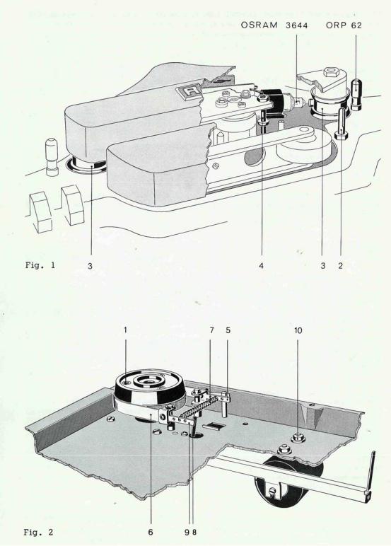
All functions are controlled by the push buttons. Arcing damage and noise is prevented by the use of diodes and RC networks. A sensing lever on the RH tape guide (3 in fig. 1 and 8) operates a switch (SE on schematic) which, in series with the stop button, provides a current path to a solenoid incorporated in the push button unit. This has the effect of clearing any selected function either by depressing the stop button or operation of the end of tape switch. On recorders up to serial No. 36 500, the function of the end of tape switch is delayed by about two seconds to avoid tripping during the start mode. On machines with higher serial numbers (recognizable by the end-of-tape switch being made of gold-plated wire with NC contact configuration) this time delay (relais) has been utilized to supply increased operating voltage to the wind motors, thus providing the required starting torque. (Inset schematic B and diagram 7.736.001-002:6 refer.)
The tape guide pins to the left and right hand side of the loading slot assist in achieving uniform tape tension due to the change in friction with varying wrap-around from large to small spooling diameters.
A three digit tape counter is driven from the take-up turntable by a rubber belt. The translucent resetting knob of the counter is lit by a small pilot bulb which acts as a mains indicator.
A remote control facility is provided
Removal of the shorting link from the socket on the rear panel and the insertion of the correct accessory plug, lead and switch, enables the recorder to be started or stopped in either the record or playback function as selected. Operation of the remote control switch has the effect of de-energizing both the capstan and brake solenoids.
ATTENTION If no remote control is used, the dummy plug must be inserted into the socket, otherwise the recorder will not start.
2.1 Mechanical checks and adjustments
It is advisable to use a full and an empty 10 1/2 inch spool when carrying out adjustments. For the majority of tape transport checks, it is essential to keep the plastic top cover in position. For other mechanical adjustments the top and head covers should be removed. To remove the plastic top plate, pull off the grey control knobs, the transparent selector discs and the plastic cover over the pinch-roller arm. Further undo the mounting screws (1 in fig. 2) of both turntables, of the head cover and the mounting lugs (2 in fig. 1) of the pinch-roller cover. When reassembling, take
great care in tightening the turntable screws uniformly to prevent them from wobbling. For best results, they may have to be rotated by 120°.
2.1.1 Tape path
The tape path level is determined by the left and right hand tape guides (3 in fig. 1) and by a small guide (4) positioned between the playback head and the capstan. We do not recommend that these guides should be interfered with in any way.
Adjustment to the spool carrier height can of course be made to enable the tape to be wound centrally between the spool flanges. This is brought about by sliding shimwashers of varying thickness onto the spooling motor shafts after removal of the bakelite brake drums. To pull a brake drum off the shaft, screws should be inserted into the three tapped holes (1 in fig. 2) so as to serve as “handles”. Care should be taken to prevent damage of the brake bands at this stage. Where a brake drum has to be removed it is recommended that the brake band be removed first.
2.1.2 Brakes
The layout of the brake system is shown in fig. 2. The mounting bracket (5 in fig. 2) on the rear end (stationary) of the brake band must be held tight against the vertical pin on the chassis by sufficient tension of the leaf-spring on the bracket.
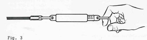
It is important to check that the brake band (6) is running flat on the brake lining and not biting on the upper or lower edge. Adjust alignment of brake band by slightly pivoting it in the rivets if required.
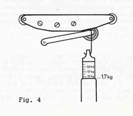
Correct tension for spring 7 is obtained when 160-220 grams applied as a tangent force to a 10 cm diam (spool and tape) causes the spool to move. See fig. 3.
Brake tension may be altered by resetting the brake return spring (7) into any of the three holes on the end-brackets (5 and 9). The brake release solenoid must cause sufficient movement (approx. 3 mm) of the front-end bracket (9) to fully free the brake band from the lining.
Depress the “stop” and “play” buttons simultaneously to energize the brake release solenoid. If the movement is incorrect, loosen the nuts (10) and re-position the solenoid. The front-end brackets of the brake bands may be bent to achieve simultaneous release of both brakes.
The brakes should be kept clean and dry. Do not use any oil or grease on the linings.
2.1.3 Tape tension
Back tension is applied by the combination of reverse direction torque from the feed motor and the degree of wrap around on the LH guide pin. Wear on the mechanical parts of the recorder will not alter the amount of tape tension. Any effects that could be attributed to inaccurate tape tension may be caused by:
a.Faulty adjustment of the brake band
b.Electrical fault in feed motor
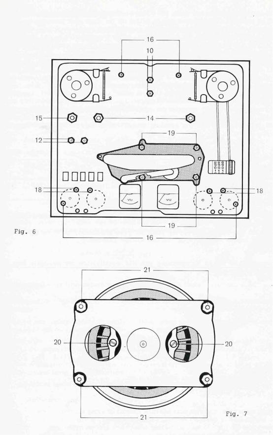
c.Electrical fault in phase shift-condenser (C 72 pos. 22 in fig. 5 and 6).
2.1.4 Pinch roller
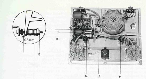
The pressure of the pinch roller can be measured by a gauge fixed to the pinch roller arm as close as possible to the spindle of the pinch roller (fig. 4). A constant tone tape should be played and the pinch roller withdrawn by the gauge until the note is heard to change. A reading in the region of 1.7 kg should be obtained. Adjustment to this value can usually be obtained by turning nut no 13 in fig. 5. Should this not provide the necessary amount of correction it is advisable to check the position of the solenoid no 11 in fig. 5 which will be correct when there is approx. 0.5 mm clearance at point A (fig. 5) with the solenoid energized. It is essential that the solenoid’s-slug fully bottoms in the energized position and when properly adjusted, there should be no movement of the slug when lifting the pinch roller off the capstan. Correct setting can be obtained by loosening the nuts (12 in fig. 6) and moving the solenoid in the required direction.
2.1.5 End of tape switch
A.Photoelectric end-of-tape-switch
Recorders with serial numbers from 58 000 onwards are equipped with a light sensitive auto shut-off device. It consists of a light source (Osram 3644), the photoresistor ORP 62 and a printed circuit section containing two transistors (see fig. 1).
The photoconductive cell is housed in the tape guide pin on the right hand side of the recorder. It has a dark resistance of greater than 100 kΩ and this value drops to below 3300 Ω under illumination. The associated current amplifier energizes the push button release solenoid when light reaches the photoconductor. For normal operation of the recorder the sensing element is at its high dark resistance and both transistors are biased into cut-off. Illumination of the photo-resistor changes the bias condition on T1 thereby raising its collector current. A voltage drop develops across the solenoid winding and T2 begins to conduct. Since T2 opens a current path parallel to the photoconductor, positive feed back action sets in which causes the collector current of T1 to rise quickly into saturation.
To de-energize the solenoid and to restore the nonconducting condition, the supply voltage has to be interrupted.
B.Mechanical end-of-tape switch.
This switch and its associate operating levers must be thoroughly clean to function correctly. On G-36 recorders up to serial number 36 500, the tape sensing lever operates a snap-action switch (SE schematic A) which is closed with tape tension applied. The right position of the switch assembly is essential for correct operation to be obtained. This adjustment is carried out by slackening the fixing screws and moving the switch bodily until the snap-action switch closes when the sensing lever still protrudes by 0.5 to 1 mm from the outer diameter of the tape guide.
On recorders with serial number 36 500 and up, the sensing lever operates a goldplated wire contact. This switch opens when tape tension is applied (see BE in schematic Band 7.736.001-002). Adjustment should be carried out analogue to the above specifications for the snap-action switch by bending the long wire loop. In the resting position sufficient contact pressure should be available to make the short wire loop move beyond the point of contact by approx. 0.5 mm. This is achieved by bending the contact wires while operating the tape sensing lever by hand.
The end-of-tape switch and its operating lever are then properly adjusted when the switch remains open (or closed on older models) for any movement of the sensing lever inside the tape-guide post. Accidental tripping due to sticky splices etc. will thus be avoided.
2.1.6 Wow and flutter
Accurate and useful measurement of wow and flutter can only be made with an appropriate instrument. The recorder is calibrated using the EMT Model 420. Possible causes of flutter may well lie with the capstan, capstan motor. Wow can usually be seen as associated with the pinch roller speed and in some cases a faulty pinch roller may be the cause, and in others too much back tension or insufficient pinch roller pressure. For all wow and flutter investigations the transport mechanism must be completely clean.
2.1.7 Tape speed
Tape speeds can be checked by running a marked, measured length of tape through the recorder. For a 100 sec. run 950cm would be required at 3 3/4 ips and 1905 cm at 7 1/2 ips. The difference in running time in seconds will be the speed variance as a percentage. Some variance can be expected with temperature increase but this should lie within the quoted tolerance. In very cold weather it may be noted that the recorder runs accurately at 3 3/4 ips but slows down when switched to 7 1/2 ips. This is due to drag from the cold grease in the capstan bearing, especially when new. After a short time of operation at 3 3/4 the machine should be capable of running at 7 1/2 ips.
When detecting any deviations from the figures quoted, an accurate reading of the mains frequency should be taken first before investigating pinch-roller pressure, brakes etc. On a 50 cycle power line, a drop to 49.5 cycles will make the recorder run slow by 1% and this should be borne in mind when checking equipment with a specified accuracy of ± 0.3 percent.
2.2 Routine maintenance
2.2.1 Cleaning
From time to time the working parts of the recorder which come in contact with the tape should be thoroughly cleaned. Cleaning of the head faces is particularly important, especially in the case of four track heads where seemingly invisible particles can often have an adverse effect on performance. On no account must any deposits be scraped off with metallic tools. Loose tape dust, may be brushed off. For cleaning of the heads and capstan shaft, use a cotton-swab soaked with methylated spirits. (Avoid any solvents from coming into contact with the plastic parts of the recorder).
2.2.2 Lubrication
The capstan motor, the capstan bearing and the wind motors are equipped with bearings of sintered material. Each bearing has an adequate supply of lubricant which should last for the life of the bearing. Should the replacement of a motor bearing become necessary, return the unit to the nearest REVOX Repair Station. On wind motors with ball bearings (Series I and II) it is advisable to replace the ball bearings
once their supply of lubricant has been used up. Felt linings are to be saturated with Teresso 43 (Esso).
If signs of wear become visible on the capstan shaft, the whole bearing plate complete with shaft should be replaced (see sect 2.3). Lubrication of the capstan bearings is not anticipated. However, where this can not be avoided, Teresso 43 (Esso) only must be used.
2.2.3 Servicing of solenoids
When it appears that a solenoid is tending to stick or function erratically, it should be dismantled and the slug and housing thoroughly cleaned with methylated spirits. When both parts are properly clean and dry, molybdenum grease may be rubbed into the working surfaces, which must finally be wiped dry before re-assembly.
2.2.4 Servicing of push button assembly
Conventional switch cleaners are not recommended for the high current spring contacts used in the REVOX, and where cleaning is necessary, the contacts should be polished clean. The interlocking bars and push-button shafts may require occasional greasing with molybdenum grease. Where a part of the assembly needs replacement, unscrew the four fixing screws, bend the pushbuttons to the right and ease the unit to a better working position. For better access to the switch assembly, the housing of the pinch roller solenoid should be removed by undoing the M 4 nuts (pos. 12 in fig. 6).
2.3 Removal of capstan assembly
This may become necessary where the recorder is to be used on a mains frequency which differs from that for which the recorder was manufactured, or when replacing the capstan assembly becomes necessary.
Having removed the chassis, as described in sect. 2.1. from the cabinet and the loudspeaker and panel, separate upper and lower chassis sections by undoing screws no 16 shown in fig. 6. Lift upper chassis without exerting excessive force, if necessary loosen the fixing screws of the selector switches (18 in fig. 6) to gain more freedom of movement.
Unscrew the capstan mounting nuts (19 in fig. 6) and remove the assembly downwards and forwards out of the chassis. The fixing screws 20 in fig. 7 on the flexible coupling are to be removed through the large holes in the capstan bearing plate. The motor mounting screws (21 fig. 7) should now be removed using REVOX’s special 8 mm nut driver, after which the flywheel assembly can be separated from the motor.
3 Electronic Description
Access to the majority of the electronics of. the recorder can be obtained by removing the base of the recorder. The REVOX G-36 has two identical recordand replaychannels. The common bias and erase Oscillator can be switched onto either one or both channels, thus allowing stereophonic recordings, two-track sound with sound and monophonic recordings. Each channel is equipped with pre-amplifier stages to accept low-level signals from linear high-impedance sources. (Step-up transformers are required where low-impedance dynamic microphones are being used.) For monitoring the signal level, the recorder is equipped with two VU-meters and associated matching amplifiers. The built in power amplifier drives a 21 cm Ø loudspeaker and an appropriate switching arrangement permits listening to either one - or both channels, before and after tape.
3.1 Circuit checks and adjustments
3.1.1 Measuring instruments
The following items are essential:
a)10 000 Ω/V DC Multi range meter
b)VTVM with min. sensitivity of 3 mV full scale
c)Low distortion audio generator
d)Appropriate calibration tape (use “REVOX Bezugsband” or “Bezugsband” 19 DIN 45513" both of which have a frequency response corresponding to the G-36 equalization characteristic)
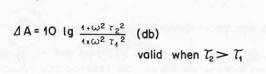
Where a test tape with response characteristics of the recorder under examination is not available, other test tapes may be used and a set of correction figures for the individual frequencies can be obtained from the following equation:
Ґ1 and Ґ2 designate the time constants of the equalization characteristics.
Other desirable but not essential instruments include a Distortion Factor Meter and an Oscilloscope.
Direct record and replay figures can only be taken when a suitable bias filter is connected between the output of the recorder and the measuring instrument.
An external filter will not be necessary for those REVOX G-36 Recorders which are already equipped with the bias-suppression circuit (printed circuit with L3, L4, C 48, C76, C77, C78, R112 and R113 on amplifier chassis to the left of P1, see fig. 14 and
schematic G-36) provided that the residual RF-signal is at least 35 db below peak record level (3 % distortion).
A wowand flutter meter may be required in rare instances only.
3.1.2 De-magnetising
From time to time the ferrous parts in contact with the tape may become magnetised. When this occurs, especially with head magnetisation, an increase in background noise will be evident and in serious instances, partial erasure of the tape may come about. De-magnetisation should be carried out with the appropriate instrument at frequent intervals and care should be taken at all times to ensure that magnetised tools do not come in contact with the head assembly. Permanent damage may be caused to a calibration tape by magnetised sound heads, as they will tend to partially erase the high frequencies on the tape. They may also have some adverse effects on the overall performance of the recorder.
3.1.3 Head alignment
Head adjustment should only be necessary when a head requires replacement or where the setting has been interfered with.
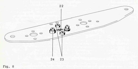
Five adjustment screws are provided I their functions are as follows:
The centre screw no 22 must be undone to remove the head or to adjust the head around the vertical axis. Adjust screw no 23 at the rear of the head for height, which will be correct when the upper brass spacer of the heads is divided by the upper tape edge. Front screw no 23 should then be adjusted to bring the head face vertical with the tape. Azimuth adjustment must be carried out by turning nut no 24.
Azimuth adjustment of playback head
Good high frequency response is possible only when the gaps of the recordand playback heads are parallel to each other. Where recordings are to be exchanged for replaying on other machines, it is furthermore essential that the head gaps are accurately aligned to an angle of 90° against the direction of tape travel.
Correct adjustment is achieved by proceeding as follows:
-connect VTVM to the output of one channel
-run alignment tape and adjust nut 24 until a maximum reading is obtained from the VTVM (observe the instructions included with the tape)
When correctly aligned, a sharp maximum will be indicated and the signal level must drop when turning nut 24 in either direction.
Azimuth adjustment of record head
It is essential that the playback head has been aligned as outlined above.
-record 12 kc/s on good quality blank tape
-with the output coupled to a VTVM nut 24 of the record head should be adjusted to give maximum output from the tape.
It is of little significance which of the two channels is used for carrying out the azimuth adjustment, however, it is advisable to check the performance of the other channel also.
Head adjustment by the phase check method
The azimuth position of the head gap on stereo tape recorders influences not only the signal level at high frequencies, it also effects the phase relation between channels. The criterion of minimum phase deviation provides a more accurate indication of correct gap angle than the adjustment for maximum output level.
To avoid a phase angle error of 90°, the azimuth should first get aligned by adjusting for level maximum.
A simple method for adjusting phase can be seen from the diagram fig. 9. Both channels are connected in parallel and azimuth adjustment is carried out at a test frequency of 10 kc/s to give maximum output from the tape. Where a double beam oscilloscope is available this should be employed so that traces from both channels can be observed simultaneously. Accurate azimuth alignment will permit phase to be maintained between channels at all frequencies, when correctly aligned a change of frequency will not affect the locking of phase between channels.
To adjust the record head ensure that playback head is correct. Using the playback channel as a measuring reference, a signal of 10 kc/s should be recorded and the record head adjusted to give maximum playback output. Again the phase check method may be employed and this will have the effect of phasing the machine from input to output via tape at all frequencies.

Adjustment of four track heads
This is a highly delicate operation as with a track separation of only 3/16", slight inaccuracies in head alignment cause a track overlap and lead to the very annoying “dead channel” cross-talk.
Where a four track recorder is under examination, it is advisable to obtain the REVOX four track alignment tape.
Relevant instructions are included with the tape.
3.1.4 Playback amplifier
Before any tests are made on the playback section of the recorder, it is essential to ensure that the sound heads are scrupulously clean; minute particles may cause false readings by partially lifting the tape off the heads.
Connect a VTVM to the cathode follower output of each channel in turn. A reference signal recorded at 32 millimaxwell per 1 mm of tape width should give an output of approximately 3 db below that specified in the technical data (refer to 5.). The frequency response section of the calibration tape is normally recorded 20 db below this level for measuring the performance characteristics of the playback channels.
A response of + 2/-3 db referred to the level at 1 kc/s is acceptable. Where unsatisfactory figures are obtained it is advisable to replace the playback head as outlined in 3.1.3. and take new readings. Should this not bring about the desired improvement, the playback pre-amplifier should be examined. Remove the earth connection of the playback head and insert a 10Ω resistor in series (fig.10.)
 Loading...