

Page 1
REJ10J0768-1000
r
E8 Emulato
User's Manual
R0E000080KCE00E
Renesas Microcomputer Development Environment System
Rev.10.00
Aug. 1, 2007
Page 2

Notes regarding these materials
1. This document is provided for reference purposes only so that Renesas customers may select the appropriate
Renesas products for their use. Renesas neither makes warranties or representations with respect to the
accuracy or completeness of the information contained in this document nor grants any license to any
intellectual property rights or any other rights of Renesas or any third party with respect to the information in
this document.
2. Renesas shall have no liability for damages or infringement of any intellectual property or other rights arising
out of the use of any information in this document, including, but not limited to, product data, diagrams, charts,
programs, algorithms, and application circuit examples.
3. You should not use the products or the technology described in this document for the purpose of military
applications such as the development of weapons of mass destruction or for the purpose of any other military
use. When exporting the products or technology described herein, you should follow the applicable export
control laws and regulations, and procedures required by such laws and regulations.
4. All information included in this document such as product data, diagrams, charts, programs, algorithms, and
application circuit examples, is current as of the date this document is issued. Such information, however, is
subject to change without any prior notice. Before purchasing or using any Renesas products listed in this
document, please confirm the latest product information with a Renesas sales office. Also, please pay regular
and careful attention to additional and different information to be disclosed by Renesas such as that disclosed
through our website. (http://www.renesas.com )
5. Renesas has used reasonable care in compiling the information included in this document, but Renesas
assumes no liability whatsoever for any damages incurred as a result of errors or omissions in the information
included in this document.
6. When using or otherwise relying on the information in this document, you should evaluate the information in
light of the total system before deciding about the applicability of such information to the intended application.
Renesas makes no representations, warranties or guaranties regarding the suitability of its products for any
particular application and specifically disclaims any liability arising out of the application and use of the
information in this document or Renesas products.
7. With the exception of products specified by Renesas as suitable for automobile applications, Renesas
products are not designed, manufactured or tested for applications or otherwise in systems the failure or
malfunction of which may cause a direct threat to human life or create a risk of human injury or which require
especially high quality and reliability such as safety systems, or equipment or systems for transportation and
traffic, healthcare, combustion control, aerospace and aeronautics, nuclear power, or undersea communication
transmission. If you are considering the use of our products for such purposes, please contact a Renesas
sales office beforehand. Renesas shall have no liability for damages arising out of the uses set forth above.
8. Notwithstanding the preceding paragraph, you should not use Renesas products for the purposes listed below:
(1) artificial life support devices or systems
(2) surgical implantations
(3) healthcare intervention (e.g., excision, administration of medication, etc.)
(4) any other purposes that pose a direct threat to human life
Renesas shall have no liability for damages arising out of the uses set forth in the above and purchasers who
elect to use Renesas products in any of the foregoing applications shall indemnify and hold harmless Renesas
Technology Corp., its affiliated companies and their officers, directors, and employees against any and all
damages arising out of such applications.
9. You should use the products described herein within the range specified by Renesas, especially with respect
to the maximum rating, operating supply voltage range, movement power voltage range, heat radiation
characteristics, installation and other product characteristics. Renesas shall have no liability for malfunctions or
damages arising out of the use of Renesas products beyond such specified ranges.
10. Although Renesas endeavors to improve the quality and reliability of its products, IC products have specific
characteristics such as the occurrence of failure at a certain rate and malfunctions under certain use
conditions. Please be sure to implement safety measures to guard against the possibility of physical injury, and
injury or damage caused by fire in the event of the failure of a Renesas product, such as safety design for
hardware and software including but not limited to redundancy, fire control and malfunction prevention,
appropriate treatment for aging degradation or any other applicable measures. Among others, since the
evaluation of microcomputer software alone is very difficult, please evaluate the safety of the final products or
system manufactured by you.
11. In case Renesas products listed in this document are detached from the products to which the Renesas
products are attached or affixed, the risk of accident such as swallowing by infants and small children is very
high. You should implement safety measures so that Renesas products may not be easily detached from your
products. Renesas shall have no liability for damages arising out of such detachment.
12. This document may not be reproduced or duplicated, in any form, in whole or in part, without prior written
approval from Renesas.
13. Please contact a Renesas sales office if you have any questions regarding the information contained in this
document, Renesas semiconductor products, or if you have any other inquiries.
Page 3

Introduction
This manual describes the followings
- E8 Emulator functions
- Preparation before use
- Debugger functions
- Tutorial
- Appendix: (Components of the E8 Emulator, Notes on High-performance Embedded
Workshop, and Diagnostic Test Procedure)
This manual does not intend to explain how to write C/C++ or assembly language programs, how
to use any particular operating system or how best to tailor code for the individual devices. These
issues are left to the respective manuals.
®
Microsoft
IBM is a registered trademark of International Business Machines Corporation.
All brand or product names used in this manual are trademarks or registered trademarks of their
respective companies or organizations.
and Windows® are registered trademarks of Microsoft Corporation.
Page 4

Document Conventions
This manual uses the following typographic conventions:
Table 1 Typographic Conventions
Convention Meaning
[Menu->Menu Option] Bold text with ‘->’ is used to indicate menu options
(for example, [File->Save As...]).
FILENAME.C Uppercase names are used to indicate filenames.
“enter this string” Used to indicate text that must be entered (excluding the “” quotes).
Key + Key Used to indicate required key presses. For example, CTRL+N means
press the CTRL key and then, whilst holding the CTRL key down,
press the N key.
(The “how to” symbol)
When this symbol is used, it is always located in the left hand margin.
It indicates that the text to its immediate right is describing “how to”
do something.
Page 5

IMPORTANT
READ FIRST
Before using this product, be sure to read the user’s manual (this user's manual) carefully.
Keep this user’s manual, and refer to this when you have questions about this product.
Emulator:
The emulator in this document refers to the following products that are manufactured by Renesas
Technology Corp.:
(1) Emulator
(2) User system interface cable
The emulator herein does not include the customer’s user system and host machine.
Purpose of use of the emulator:
This emulator is a device to support the development of a system that uses the Renesas MCUs. It
provides support for system development in both software and hardware.
Be sure to use this emulator correctly according to said purpose of use. Please avoid using this
emulator for other than its intended purpose of use.
For those who use this emulator:
This emulator can only be used by those who have carefully read the user’s manual and know how
to use it.
Use of this emulator requires the basic knowledge of electric circuits, logical circuits, and MCUs.
When using the emulator:
(1) This product is a development supporting unit for use in your program development and
evaluation stages. In mass-producing your program you have finished develop ing, be sure to
make a judgment on your own risk that it can be put to practical use by performing
integration test, evaluation, or some experiment else.
(2) In no event shall Renesas Solutions Corp. be liable for any consequence arising from the use
of this product.
(3) Renesas Solutions Corp. strives to renovate or provide a workaround for product malfunction
at some charge or without charge. However, this does not necessarily mean that Renesas
Solutions Corp. guarantees the renovation or the provision under any circumstances.
(4) This product has been developed by assuming its use for program development and
evaluation in laboratories. Therefore, it does not fall under the application of Electrical
Appliance and Material Safety Law and protection against electromagnetic interference when
used in Japan.
(5) Renesas Solutions Corp. cannot predict all possible situations or possible cases of misuse
where a potential danger exists. Therefore, the warnings written in this user’s manual and the
warning labels attached to this emulator do not necessarily cover all of such possible
situations or cases. Please be sure to use this emulator correctly and safely on your own
responsibility.
(6) This product is not qualified under UL or other safety standards and IEC or other industry
standards. This fact must be taken into account when taking this product from Japan to some
other country.
Page 6

Usage restrictions:
This emulator has been developed as a means of supporting system development by users.
Therefore, do not use it as a device used for equipment-embedded applications. Also, do not use it
for developing the systems or equipment use d fo r the foll o wi n g pu r poses either:
(1) Transportation and vehicular
(2) Medical (equipment where human life is concerned)
(3) Aerospace
(4) Nuclear power control
(5) Undersea repeater
If you are considering the use of this emulator for one of the above purp oses, please be sure to
consult your local distributor.
About product changes:
We are constantly making efforts to improve the design and performance of this emulator.
Therefore, the specification or design of this emulator or its user’s manual may be changed
without prior notice.
About the rights:
We assume no responsibility for any damage or infringement on patent rights or any other rights
arising from the use of any information, products or circuits presented in this user’s manual.
(1) We assume no responsibility for any damage or infringement on patent rights or any other
rights arising from the use of any information, products or circuits presented in this user’s
manual.
(2) The information or data in this user’s manual does not implicitly or otherwise grant a license
for patent rights or any other rights belonging to us or third parties.
(3) This user’s manual and this emulator are copyrighted, with all rights reserved by us. This
user’s manual may not be copied, duplicated or reproduced, in whole or part, without prior
written consent of us.
About diagrams:
The diagrams in this user’s manual may not all represent exactly the actual object.
Device names:
Chapters 1 through 6 of the Debugger Part in this user’s manual use R8C/Tiny as an example of
the device names.
Guarantee:
If your product becomes faulty within one year after its purchase while being used under good
conditions by observing "IMPORTANT" and "Precautions for Safety" described in this user's
manual, we will repair or replace your faulty product free of charge. Note, however, that if your
product's fault is raised by any one of the following causes, we will repair it or replace it with new
one with extra-charge:
- Misuse, abuse, or use under extraordinary conditions
- Unauthorized repair, remodeling, maintenance, and so on
- Inadequate user's system or misuse of it
- Fires, earthquakes, and other unexpected disasters
In the above cases, contact your local distributor.
Page 7

Precautions for Safety
READ FIRST
Before using this product, be sure to read the user’s manual (this user's manual) carefully.
Keep this user’s manual, and refer to this when you have questions about this product.
Page 8
DEFINITION OF SIGNAL WORDS
Be sure to read and understand the warnings below before using this emulator. Note that these are
the main warnings, not the complete list.
This is the safety alert symbol. It is used to alert you to potential personal
injury hazards. Obey all safety messages that follow this symbol to avoid
possible injury or death.
DANGER
avoided, will result in death or serious injury.
WARNING
avoided, could result in death or serious injury.
CAUTION
avoided, may result in minor or moderate injury.
CAUTION
potentially hazardous situation which, if not avoided, may result
in property damage.
DANGER indicates an imminently hazardous situation which, if not
WARNING indicates a potentially hazardous situation which, if not
CAUTION indicates a potentially hazardous situation which, if not
CAUTION used without the safety alert symbol indicates a
NOTE emphasizes essential information.
Page 9

WARNING
1. Do not repair or remodel the emulator product by
yourself for electric shock prevention and quality
assurance.
2. Always switch OFF the host computer and user system
before connecting or disconnecting any CABLES or
PARTS.
Failure to do so will result in a FIRE HAZARD and will
damage the user system and the emulator product or will
result in PERSONAL INJURY. The USER PROGRAM will
be LOST.
3. Connect the connectors in the user system and in the
user interface cable by confirming the correct direction.
CAUTION
Place the host computer and user system so that no cable is
bent or twisted. A bent or twisted cable will impose stress on
the user interface leading to connection or contact failure.
Make sure that the host computer and the user system are
placed in a secure position so that they do not move during
use nor impose stress on the user interface.
Page 10

Page 11

Contents
Contents 1
Section 1 Overview........................................................................................... 1
1.1 Warnings...........................................................................................................................3
1.2 Environmental Cond itions ................................................................................................4
1.3 Components ......................................................................................................................5
Section 2 E8 Emulator Functions ..................................................................... 7
2.1 Overview..............................................................................................................................7
2.2 Trace Functions....................................................................................................................9
2.3 Break Functions...................................................................................................................10
2.4 Memory Access Functions...................................................................................................11
2.5 Stack Trace Function...........................................................................................................12
2.6 Online Help..........................................................................................................................12
Section 3 Preparation before Use...................................................................... 13
3.1 Emulator Preparation...........................................................................................................13
3.2 Emulator Hardware Configuration.......................................................................................15
3.3 Emulator Software Configuration........................................................................................19
3.3.1 CD..........................................................................................................................19
3.4 Installing Emulator’s Debugger...........................................................................................20
3.5 Connecting the Emulator to the Host Computer..................................................................21
3.6 Connecting the Emulator to the User System......................................................................23
3.7 Connecting System Ground.................................................................................................25
3.8 System Check ......................................................................................................................26
3.9 Uninstalling the Emulator’s Debugger ................................................................................35
Section 4 Preparations for Debugging.............................................................. 39
4.1 Method for Activating High-performance Embedded Workshop.....................................39
4.1.1 Creating the New Workspace (Toolchain Not Used)...........................................40
4.1.2 Creating the New Workspace (Toolchain Used)..................................................44
4.1.3 Selecting an Existing Workspace.........................................................................56
4.2 Setting at E8 Emula tor Activation ....................................................................................58
4.2.1 Setting at Emulator Activation.............................................................................58
4.2.2 Downloading a Program ......................................................................................60
4.2.3 Setting the Writing Flash Memory Mode ............................................................61
Section 5 Debugging......................................................................................... 71
5.1 Setting the Environment for Emulation ............................................................................71
Page 12

5.1.1 Opening the [Configuration] Dialog Box ............................................................71
5.1.2 [General] Page .....................................................................................................72
5.2 Downloading a Program ...................................................................................................74
5.2.1 Downloading a Program ......................................................................................74
5.2.2 Viewing the Source Code....................................................................................75
5.3 Stopping Your Program ....................................................................................................78
5.3.1 Address Interrupt Breakpoints .............................................................................78
5.4 Using the Even t Points......................................................................................................79
5.4.1 PC Breakpoints....................................................................................................79
5.4.2 Break Conditions .................................................................................................79
5.4.3 Opening the [Event] Window..............................................................................79
5.4.4 Setting PC Breakpoints........................................................................................79
5.4.5 Add ......................................................................................................................80
5.4.6 Edit.......................................................................................................................80
5.4.7 Enable..................................................................................................................80
5.4.8 Disable.................................................................................................................80
5.4.9 Delete...................................................................................................................80
5.4.10 Delete All.............................................................................................................80
5.4.11 Go to Source ........................................................................................................81
5.4.12 [Set Break] Dialog Box........................................................................................81
5.4.13 Setting Break Conditions.....................................................................................82
5.4.14 Edit.......................................................................................................................83
5.4.15 Enable..................................................................................................................83
5.4.16 Disable.................................................................................................................84
5.4.17 Delete...................................................................................................................84
5.4.18 Delete All.............................................................................................................84
5.4.19 Go to Source ........................................................................................................84
5.4.20 Sequential Conditions..........................................................................................84
5.4.21 Editing Break Conditions..................................................................................... 84
5.4.22 Modifying Break Conditions ...............................................................................84
5.4.23 Enabling Break Conditions..................................................................................84
5.4.24 Disabling Break Conditions.................................................................................84
5.4.25 Deleting Break Conditions...................................................................................85
5.4.26 Deleting All Break Conditions.............................................................................85
5.4.27 Viewing the Source Line for Break Conditions...................................................85
5.4.28 [Break condition x] Dialog Box...........................................................................85
5.5 Viewing the Trace Information.........................................................................................87
5.5.1 Opening the [Trace] Window ..............................................................................87
5.5.2 Acquiring Trace Information...............................................................................87
5.5.3 Clearing the Trace Information............................................................................88
5.5.4 Saving the Trace Information in a File................................................................88
5.5.5 Viewing the [Source] Window ............................................................................88
5.5.6 Trimming the Source...........................................................................................88
Page 13

5.6 Using the Start/Stop Function................................................................................................89
5.6.1 Opening the [Start/Stop Function Set t i ng] Di al og B o x........................................89
5.6.2 Specifying the Routine to be Executed................................................................89
5.6.3 Restrictions on the Start/Stop Function................................................................91
Section 6 Tutorial.............................................................................................. 93
6.1 Introduction..........................................................................................................................93
6.2 Running the High-perfo rmance Embedded Workshop........................................................94
6.3 Setting up the E8 Emulator..................................................................................................94
6.4 Setting the [Configuration] Dialog Box...............................................................................95
6.5 Checking the Operation of RAM.........................................................................................97
6.6 Downloading the Tutorial Program.....................................................................................99
6.6.1 Downloading the Tutorial Program........................................................................99
6.6.2 Displaying the Source Program..............................................................................100
6.7 Setting a PC Breakpoint.......................................................................................................101
6.8 Setting Registers..................................................................................................................102
6.9 Executing the Program.........................................................................................................104
6.10 Reviewing Breakpoints......................................................................................................107
6.11 Viewing Memory...............................................................................................................108
6.12 Watching Variables............................................................................................................109
6.13 Stepping Through a Program.............................................................................................112
6.13.1 Executing [Step In] Command.............................................................................112
6.13.2 Executing [Step Out] Com m a nd..........................................................................113
6.13.3 Executing [Step Over] Com mand ........................................................................114
6.14 Forced Breaking of Program Executions...........................................................................115
6.15 Displaying Local Variables................................................................................................116
6.16 Break Function...................................................................................................................117
6.16.1 PC Break Function...............................................................................................117
6.17 Hardware Break Function..................................................................................................121
6.18 Trace Functions..................................................................................................................124
6.18.1 Displaying the Trace Window..............................................................................124
6.19 Stack Trace Function.........................................................................................................125
6.20 What Next?........................................................................................................................127
Appendix A Components of the E8 Emulator.................................................. 129
Appendix B Window Functions........................................................................ 131
Appendix C Command-Line Functions............................................................ 135
Appendix D Notes on High-performance Embedded Workshop..................... 137
Appendix E Diagnostic Hardware Program ..................................................... 143
Page 14

E.1. System Setup to Execute the Check Program...................................................................143
E.2. Executing the Check Program...........................................................................................143
E.3 When an Error Occurs.......................................................................................................145
Page 15

Page 16

Page 17
Section 1 Overview
The High-performance Embedded Workshop is a Graphical User Interface intended to ease the
development and debugging of applications written in C/C++ programming language and
assembly language for Renesas microcomputers. Its aim is to provide a powerful yet intuitive way
of accessing, observing and modifying the debugging platform in which the application is running.
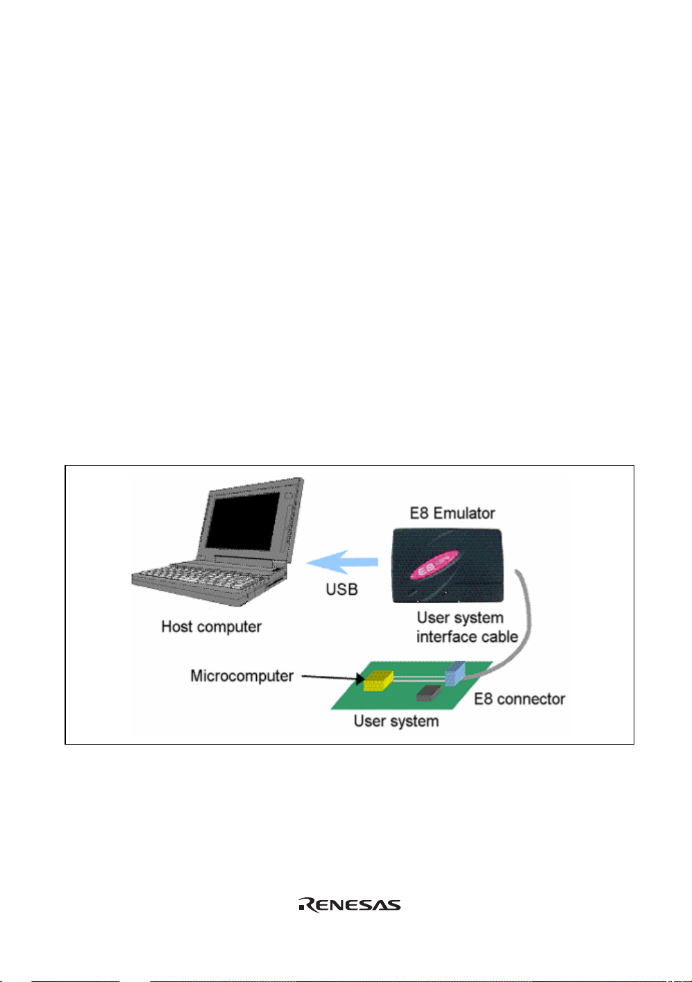
The E8 emulator (hereafter referred to as the emulator) is a software and hardware development
support tool for application systems using the Renesas microcomputer. For applicable MCUs,
refer to the web site.
The main unit of the emulator is connected through the dedicated debugging interface to the user
system. The user system can be debugged under the conditions similar to the actual application
conditions. The emulator enables debugging anywhere indoors or out. The host computer for
controlling the emulator must be an IBM PC compatible machine with USB.
This manual describes the contents that comply with versions of the High-performance Embedded
Workshop 4.0 or later.
Figure 1.1 shows the system configuration using the emulator.
Figure 1.1 System Configuration with the Emulator
1
Page 18

The emulator has three activation modes:
(1) A mode in which the emulator program is started after it has been downloaded to the target
device:
This mode is used when there is no emulator program in the flash memory of the target device.
(2) A mode in which the emulator program is started without downloading it to the target device:
This mode is used when there is an emulator program in the flash memory of the target device.
(3) A mode in which the emulator is used as the flash memory programmer:
This mode is used when the emulator is used for programming the flash memory.
The emulator provides the following features:
(1) Excellent cost-performance card emulator
Compactness and USB connection are obtained.
(2) Realtime emulatio n
Realtime emulation of the user system is enabled at the maximum operating frequency of the
MCU.
(3) Excellent operability
Using the High-performance Embedded Wo rkshop on the Microsoft
Microsoft
®
Windows® XP operating system enables user program debugging using a pointing
®
Windows® 2000, or
device such as a mouse.
(4) Various debugging functions
Various break and trace functions enable efficient debugging. Breakpoints and break
conditions can be set by the specific window, trace information can be displayed on a window,
and command-line functions can be used.
(5) Debugging of the user system in the final development stage
The user system can be debugged under conditions similar to the actual application conditions.
(6) Compact debugging environment
A laptop computer can be used as a host computer, creating a debugging environment in any
place.
(7) The emulator can be used to program the internal flash memory.
2
Page 19

1.1 Warnings
CAUTION
READ the following warnings before using the emulator
product. Incorrect operation will damage the user system and
the emulator product. The USER PROGRAM will be LOST.
(1) Check all components against the component list provided at the side of the component box
after unpacking the emulator.
(2) Never place heavy objects on the casing.
(3) Protect the emulator from excessive impacts and stresses. For details, refer to section 1.2,
Environmental Conditions.
(4) When moving the host computer or user system, take care not to vibrate or damage it.
(5) After connecting the cable, check that it is connected correctly. For details, refer to section 3,
Preparation before Use.
(6) Supply power to the connected equipment after connecting all cables. Cables must not be
connected or removed while the power is on.
3
Page 20

1.2 Environmental Conditions
CAUTION
Observe the conditions listed in tables 1.1 and 1.2 when using
the emulator. Failure to do so will cause illegal operation in
the user system, the emulator product, and the user program.
Table 1.1 Environmental Conditions
Item Specifications
Temperature Operating: +10°C to +35°C
Storage: –10°C to +50°C
Humidity Operating: 35% RH to 80% RH, no condensation
Storage: 35% RH to 80% RH, no condensation
Vibration Operating: 2.45 m/s2 max.
Storage: 4.9 m/s
Transportation: 14.7 m/s
Ambient gases No corrosive gases may be present
Table 1.2 Operating Environments
Item Description
Host computer IBM PC or compatible machine with built-in Pentium
performance CPU (600 MHz or higher recommended)
OS Windows® 2000, or Windows® XP
Minimum memory
capacity
Hard-disk capacity Installation disk capacity: 100 Mbytes or more. (Prepare an area at
Interface USB (USB1.1, full-speed)*
Pointing device such as
mouse
Power voltage 5.0 ± 0.25 V (USB-bus power type)
Current consumption 500 mA (max)
CD drive Required to install the software for the emulator or refer to the emulator
128 Mbytes or more (double of the load module size)
least double the memory capacity (four-times or more recommended)
as the swap area.)
Connectable to the host computer; compatible with Windows® 2000 or
Windows® XP.
user’s manual.
* Can be connected to a host machine supporting USB 2.0.
2
max.
2
max.
®
III or higher-
* Not all hardware (such as host machine, USB devices, USB hub) combination will work and
guaranteed.
4
Page 21

1.3 Components
Check all the components unpacking. For details on the E8 emulator components, refer to the
component list provided at the side of the component box. If the components are not complete,
contact our E-mail address for user registration or refer to the web site.
5
6
Page 22

Page 23

Section 2 E8 Emulator Functions
This section describes the emulator functions. They differ according to the device supported by the
emulator.
2.1 Overview
Table 2.1 gives a functional overview of the emulator.
Table 2.1 Emulator Functions
No. Item Function
1 User program execution
function
2 Reset function
3 Trace function
4 Break functions
• Executes a program with the operating frequency within a
range guaranteed by devices.
• Reset emulation
• Step functions:
Single step (one step: one instruction)
Source-level step (one step: one source)
Step over (a break did not occur in a subroutine)
Step out (when the PC points to a location within a
subroutine, execution continues until it returns to the calling
function)
• Issues a reset from the High-performance Embedded
Workshop to the device during break.
• Branch trace function incorporated in the device (four
branches)
The support of this function depends on a device.
• Hardware break condition (one condition)
The support of this function depends on a device.
• PC break condition (255 points)
• Forced break function
• Address match break function
7
Page 24

Table 2.1 Emulator Functions (cont)
No. Item Function
5 Memory access function
6 General/control register
access function
7 Internal I/O register
access function
8 Source-level debugging
function
9 Command line function Supports command input.
10 Help function Describes the usage of each function or command syntax input
• Downloading to RAM
• Downloading to flash memory
• Single-line assembly
• Reverse assembly (disassembly)
• Reading of memory
• Writing to memory
• Automatic updating of a display of selected variables during
user program execution
• FILL
• Search
• Move
• Copy
Reads or writes the general/control register.
Reads or writes the internal I/O register.
Various source-level debugging functions.
Batch processing is enabled when a file is created by arranging
commands in input order.
from the command line window.
The specific functions of the emulator are described in the next section.
8
Page 25

2.2 Trace Functions
The branch source addresses, mnemonics, operands, and source lines are displayed. Since this
function uses the trace buffer built into the device, a realtime trace can be acquired.
Note: The MCUs which have no trace function cannot use this function.
9
Page 26

2.3 Break Functions
The E8 emulator has the following four break functions.
(1) Hardware break function
H8 R8C series
Uses a break controller incorporated in the device.
The access address, instruction fetch address, data, or bus cycle condition can be set.
This function can also be set from the
refer to section 5.3.1 Address Interrupt Breakpoints.
Note: The MCUs which have no har dwa re break function cannot use this function.
(2) PC break function (BREAKPOIN T)
Breaks when the dedicated instruction at the specified address that has been replaced is
executed.
This function can be set on the [Breakpoint] page in the [Eventpoint] dialog box. It can also be
set when the [S/W Breakpoints] column for the line to be set is double-clicked in the [Source]
or [Disassembly] window.
(3) Forced break function
Forcibly breaks the user program.
[Event] column in the [Source] window. For the setting,
(4) Address match break function
Stops the target program immediately before a specified address instruction is executed. This
function is featured by the address match interrupt of the MCU. This function can be set from
the
[Event] column in the Source window. For the setting, refer to section 5.2.2, Viewing the
Source Code.
Note: The address match break points vary depending on the device. And, user program
operation when device's address match interrupts are used is not guaranteed.
10
Page 27

2.4 Memory Access Functions
The emulator has the following memory access functions.
(1) Memory read/write function
[Memory] window: The memory contents are displayed in the window. Only the amount
specified when the [Memory] window is opened can be read. If the
memory is written in the [Memory] window, a read in the range
displayed in the [Memory] window will occur for updating the window.
When the [Memory] window is not to be updated, change the setting in
[Lock Refresh] from the popup menu.
me command: A command line function that reads or writes the specified amount of
memory at the specified address.
(2) User program downloading function
A load module registered in the workspace can be downloaded. Such module can be selected
from [Download Modules] in the [Debug] menu. Downloading is also possible by a popup
menu that is opened by right-clicking on the mouse at the load module in the workspace. The
user program is downloaded to the RAM or flash memory.
This function can download information required for source-level debugging with the
Elf/Dwarf2 or IEEE695 file having the debugging information.
(3) Memory data uploading function
The specified amount of memory from the specified address can be saved in an S-format file.
(4) Memory data downloading function
The memory contents saved in the S-type-formatted file can be downloaded. Select [Load]
from the popup menu in the [Memory] window.
(5) Displaying the variable contents
The variable contents specified in the user program are displayed. For the usage of the function
for displaying the variable contents, refer to High-performance Embedded Workshop User’s
Manual.
11
Page 28

(6) Other memory operation functions
Other functions are as follows:
• Memory fill
• Memory copy
• Memory save
• Memory verify
• Memory search
• Internal I/O display
• Displaying label and variable names and their contents
Notes: 1. Memory access during user program execution:
When memory is accessed from the memory window, etc. during execution of the user
program, execution stops for the memory access and is then resumed. Therefore,
realtime emulation cannot be performed.
2. Memory access during user program break:
The program can also be downloaded and the BREAKPOINT can be set for the flash
memory area by the emulator.
2.5 Stack Trace Function
The emulator uses the information on the stack to display the names of functions in the sequence
of calls that led to the function to which the program counter is currently pointing. This function
can be used only when the load modules that have the following formats are loaded:
- M32C family C complier (M3T-NC308WA): IEEE695
- M16C family C compiler (M3T-NC30WA): IEEE695
- R8C series C compiler (M3T-NC8C): IEEE695
- H8,H8S,H8SX family C/C++ compiler (such as [R0C40008XSW06R]): Elf/Dwarf2
For the usage of this function, refer to section 6.19, Stack Trace Function.
2.6 Online Help
An online help explains the usage of each function or the command syntax that can be entered
from the command line window.
Select [Emulator Help] from the [Help] menu to view the emulator help.
12
Page 29
Section 3 Preparation before Use
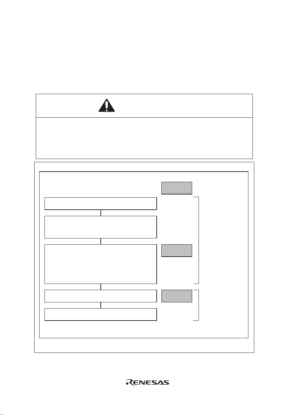
3.1 Emulator Preparation
Unpack the emulator and prepare it for use as follows:
WARNING
READ the reference sections shaded in Figure 3.1 before
using the emulator product. Incorrect operation will damage
the user system and the emulator product. The USER
PROGRAM will be LOST.
Unpack the emulator
Check the components against the comp onent
List provided at the side of t he component box .
Set up the emulator
-
Install the High- performance Embedded
Workshop
- Insert the emulator
- Set up the main unit of the emulator
Reference
Section 3
When the emulator
is used first.
Start the High-performance Embedded
Workshop
Turn on the user system
Figure 3.1 Emulator Preparation Flow Chart
Section 4
When the emulator
is used for second
time or later.
13
Page 30

14
Page 31

3.2 Emulator Hardware Configuration
As shown in Figure 3.2, the emulator consists of an emulator, a USB cable, and a user system
interface cable. The emulator is connected to the host computer via USB 1.1, and also to the USB
port conforming to USB 2.0.
Figure 3.2 Emulator Hardware Configurati on
15
Page 32

The names of each section of the emulator are explained next.
Emulator Upper-side Panel:
(d)
(c)
(a)
(b)
(e)
Figure 3.3 Emulator Upper-side Panel
(a) E8 logo plate: A pink plate dedicated for the emulator is provided to be easily
distinguished from other E-series emulators.
(b) Sliding switch cover: A cover to protect a switch for setting the emulator, which is closed
to prevent incorrect operation. Be sure to close this cover during
emulation.
(c) ACTION LED: Marked ‘ACT’. When this LED is lit, the E8 control software is in
operation.
(d) Host connector: Marked ‘
’. A connector for the host computer is provided at the
side of this mark.
(e) User connector: Marked ‘USER I/F’. A connector for the user system interface cable
is provided at the side of this mark.
Note: Even if the LED is not lit when the emulator is connected to the host computer, the USB is
not malfunctioned.
16
Page 33

Emulator Host-side Panel:
(a)
Figure 3.4 Emulator Host-side Panel
(a) Host-side connector: A USB connector for the host computer. Be sure to connect the
provided USB cable.
Emulator User-side Panel:
(a)
Figure 3.5 Emulator User-side Panel
(a) User-side connector: A user system interface cable is connected.
17
Page 34

Emulator Bottom Panel:
(a)
Figure 3.6 Emulator Bottom Panel
(a) Seal for product management: The serial number, revision, and safety standard, etc. of the
emulator are written to. The contents differ depending on the
time when you purchased the product.
18
Page 35

3.3 Emulator Software Configuration
The following item is included with the emulator debugger when it is purchased:
• E8 Emulator Debugger: R0E000080KCE00SR (CD)
3.3.1 CD
Install the software as instructed by the displayed messages by inserting the included CD into the
CD-ROM drive. The folders contain the files and programs listed below.
Table 3.1 Contents of the CD Directories
Directory Name Contents Description
Dlls Microsoft
Drivers E8 emulator driver The E8 emulator drivers.
E8SCP Self check program for the E8
emulator
Help Online help for the E8 emulator An online help file
Manuals E8 emulator manual E8 emulator user’s manual. This is provided
®
runtime library A runtime library for the High-performance
Embedded Workshop. The version is checked
at installation and this library is copied to the
hard disk as part of the installation process.
Diagnostic test program for the E8 emulator.
as a PDF file.
19
Page 36

3.4 Installing Emulator’s Debugger
When the CD is inserted in the host computer’s CD drive, execute Setup.exe from the root
directory of the CD.
20
Page 37

3.5 Connecting the Emulator to the Host Computer
This section describes how to connect the emulator to the host computer. For the position of each
connector of the emulator, refer to section 3.2, Emulator Hardware Configuration.
Notes: 1. When [Add New Hardware Wizard] is displayed, select the [Search for the best driver
for your device. (Recommended)] radio button and then the [Sp ecify a location] check
box to select the path to be searched for drivers. The location must be specified as
<Drive>:\DRIVERS. (<Drive> is the CD drive name.)
2. Be sure to install the emulator’s debugger before putting the emulator in place.
WARNING
Always switch OFF the emulator product and the user system
before connecting or disconnecting any CABLES except for
the USB interface cable. Failure to do so will result in a FIRE
HAZARD and will damage the user system and the emulator
product or will result in PERSONAL INJURY.
The USER PROGRAM will be LOST.
21
Page 38

The emulator is connected to the host computer via the USB 1.1, and also to the USB port
conforming to USB 2.0. Figure 3.7 shows the system configuration.
Figure 3.7 System Configuration when Connecting the Emulator to the Host Computer
22
Page 39

3.6 Connecting the Emulator to the User System
Use the procedure below to connect the emulator to the user system with the user system interface
cable, or to disconnect them when moving the emulator or the user system.
1. Check that the host computer is turned off or the emulator is not connected to the host
computer with the USB cable.
2. Connect the user system interface cable to the user-side connector of the emulator.
3. Connect the USB cable to the host-side connector of the emulator.
Figure 3.8 shows the position of the connector.
Connector for user system interface cable
Figure 3.8 Position of the Connector
(1) The connector must be installed to the user system. Table 3.2 shows the recommended
connector for the emulator.
Table 3.2 Recommended Connector
Type Number Manufacturer Specifications
2514-6002 3M Limited 14-pin straight type
Note: When the connector is used, do not install any components within 3 mm of the connector.
23
Page 40

(2) The pin assignments of the connector are shown in section 2 in the additional documents,
Notes on Connecting the xxxxx.
Figure 3.9 Connecting the User System Interface Cable to the User System
Notes: 1. To connect the signals output from the connector, refer to the MCU pin alignment.
2. To remove the user system interface cable from the user system, pull the tab on the
connector upward.
3. The range of frequencies that the emulator operates at is different according to the
MCUs used.
4. Connect the signals from the connector as shown in section 2 in the additional
documents, Notes on Connecting the xxxxx.
24
Page 41

3.7 Connecting System Ground
WARNING
Separate the frame ground from the signal ground at the user
system. Failure to do so will result in a FIRE HAZARD and will
damage the user system and the emulator product or will
result in PERSONAL INJURY.
The emulator's signal ground is connected to the user system's signal ground. In the emulator, the
signal ground and frame ground are connected. In the user system, connect the frame ground only;
do not connect the signal ground to the frame ground (Figure 3.10).
Signal ground
Host
computer
USB
Power
supply
E8 emulator
E7 emulator
Logic
Signal
Signal ground
Signal
Signal ground
Frame ground
User system
Logic
Figure 3.10 Connecting System Ground
25
Page 42

3.8 System Check
When the software is executed, use the procedure below to check that the emulator is connected
correctly. Here, use the workspace for a tutorial provided on the product.
Refer to section 4, Preparations for Debugging, for the other activating method to create a new
project or use a workspace for the High-performance Embedded Workshop of the old version.
1. Connect the emulator to the host computer.
2. Connect the user system interface cable to the connector of the emulator.
3. Connect the user system interface cable to the connector in the user system.
4. Select [Renesas] -> [High-performance Embedded Workshop] -> [High-performance
Embedded Workshop] from [Programs] in the [Start] menu of Windows
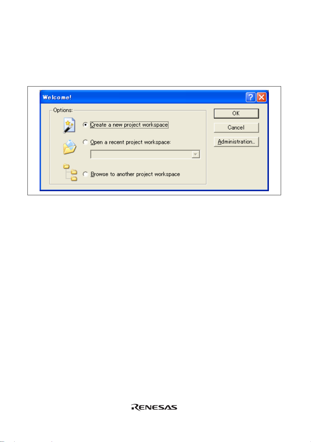
5. The [Welcome!] dialog box is displayed.
®
Figure 3.11 [Welcome!] dialog box
[Create a new project workspace] radio button: Creates a new workspace.
[Open a recent project workspace] radio button: Uses the current workspace and displays
the history of the opened workspace.
[Browse to another project workspace] radio button: Uses the current workspace; this radio
button is used when the history of the
opened workspace does not remain
To use a workspace for the tutorial, select the [Browse to another project workspace] radio button
and click the [OK] button.
26
Page 43
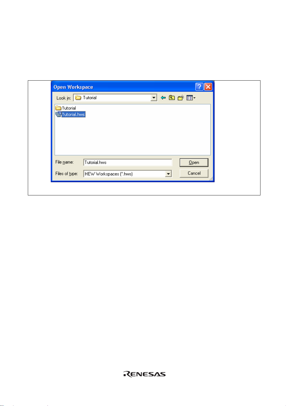
When the [Open workspace] dialog box is opened, specify the following directory:
<OS installation directory>
\WorkSpace\Tutorial\E8\xxxx\Tutorial
After the directory has been specified, select the following file and click the [Open] button.
Figure 3.12 [Open Workspace] Dialog Box
Note:
The directory for a tutorial differs depending on the device.
z M32C
Drive where the OS has been installed:
\WorkSpace\Tutorial\E8\M32C\Tutorial
z R16C
Drive where the OS has been installed:
\WorkSpace\Tutorial\E8\M16C\Tutorial
z R8C/Tiny
Drive where the OS has been installed:
\WorkSpace\Tutorial\E8\R8C\Tutorial
z H8/Tiny normal mode
Drive where the OS has been installed:
\WorkSpace\Tutorial\E8\H8\Tutorial
z H8/Tiny advanced mode
Drive where the OS has been installed:
\WorkSpace\Tutorial\E8\H8\TutorialADV
z H8/ Super Low Power
Drive where the OS has been installed:
\WorkSpace\Tutorial\E8\H8\TutorialSLP
27
Page 44

6. The [Select Emulator mode] dialog box is displayed.
Figure 3.13 [Emulator Setting] Dialog Box
Select the device name in use from the [MCU Group] drop-down list box.
Note: The [MCU Group] drop-down list box is not displayed in the H8/Tiny or H8/Super Low
Power series.
Select the device name in use from the [Device] drop-down list box.
The following items are selected in the [Mode] group box.
⎯ Erase Flash and Connect
This mode is used to erase data of the MCU flash memory and activate the debugger. A
program for the emulator is also written to at the same time.
Note: The emulator occupies the user’s flash memory area according to the target MCUs. For
details, refer to the additional document, Notes on Connecting the xxxxx.
⎯ Keep Flash and Connect
This mode is used to activate the debugger while retaining data of the MCU flash memory.
However, areas for the emulator program and vector areas used by the emulator will be
changed.
28
Page 45

⎯ Program Flash
This mode is used when the emulator is used as a flash memory programmer. It cannot be
used for debugging programs.
Register the load module in the workspace to download it.
Note: It is necessary to input the ID code of the flash memory by the target device. For details,
refer to the additional document, Notes on Connecting the xxxxx.
⎯ Debugging of CPU rewrite mode
This mode is used to debug the program that rewrites the CPU. In this mode, the following
debug operations, which require reprogramming of the flash memory, are not available:
- Setting the PC breakpoint
- Changing the memory contents in the flash memory area
The debugger is activated by erasing data of the MCU flash memory. A program for the
emulator program is also written to at the same time.
Note: This mode is not supported in the H8/Tiny or H8/Super Low Power series.
When the [Execute the user program after ending the debugger.] check box is selected, the user
program is executed at the same time as the debugger operation is ended with the emulator
connected to the user system. This check box is only available when the [Program Flash] mode
has been selected.
When the [Power Target from Emulator. (MAX 300mA)] check box is selected, power will be
supplied to the user system up to 300 mA. Then select 3.3 V or 5.0 V according to the power
voltage of the user system.
CAUTION
Before carrying out the power supply, check the power
specification of the user system and there is no short circuit
in the user system. Incorrect operation will damage the user
system and the emulator product. The USER PROGRAM will
be LOST.
29
Page 46

7. The [Connecting] dialog box is displayed and the emulator connection is started.
Figure 3.14 [Connecting] Dialog Box
8. When the version of the E8 firmware downloaded into the emulator is old, the message box
shown in Figure 3.15 will be displayed.
Figure 3.15 Dialog Box for confirming the E8 firmware download
Note: When [OK] button is clicked, it starts downloading the E8 firmware. Do not
connect/disconnect the USB cable until the download status dialog box closes.
30
Page 47

9. When [Power supply is carried out. (MAX 300mA)] is not checked, the dialog box sh own in
Figure 3.17 will be displayed.
Figure 3.16 Dialog Box of the Power-on Request Message
10. The dialog box for confirming the power supply status of the user system will be displayed.
Figure 3.17 [Power Supply] Dialog Box
When [Power supply is carried out. (MAX 300mA)] is checked, power will be supplied to the user
system up to 300 mA. Then select 3.3 V or 5.0 V according to the power voltage of the user
system.
CAUTION
Before carrying out the power supply, check the power
specification of the user system and there is no short circuit
in the user system. Incorrect operation will damage the user
system and the emulator product. The USER PROGRAM will
be LOST.
31
Page 48

11. When [Power supply is carried out. (MAX 300mA)] is not checked, power on the user system
and click the [OK] button.
12. When "Connected" is displayed in the [Output] window of the High-performance Embedded
Workshop, the emulator initiation is completed
Figure 3.18 High-performance Embedded Workshop Window
Note: When the user program has already been downloaded to the flash memory, source-level
debugging cannot be executed because there is no debugging information on the user
program after the emulator has been activated. Be sure to load the debugging information
file. For details, refer to section 4.2.1, Setting at Emulator Activation.
32
Page 49

Notes: 1. If the user system interface cable is disconnected from the connector on the user
system, the following dialog box will appear.
Figure 3.19 [Connector disconnected] Dialog Box
2. If the emulator is not properly initialized, one of the dialog boxes shown in figures 3.20
through 3.24 will appear.
(a) The following dialog box is displayed when the flash memory cannot be erased.
Exchange the MCU since the flash memory has been programmed more times than
the limitation.
Figure 3.20 [Flash memory erase error!] Dialog Box
(b) The following dialog box is displayed when the flash mem ory can not be pr ogrammed.
An incorrect system clock value has been input or the flash memory has been
programmed more times than the limitation.
Figure 3.21 [Error sending Flash memory write program] Dialog Box
33
Page 50

(c) The following dialog box is displayed when an incorrect ID code has been input. For
the H8/Tiny, H8/ Super Low Power, R8C/10, 11, 12 and 13, if an ID code does not
match, the flash memory will be completely erased.
Figure 3.22 [ID code error!] Dialog Box
(d) The following dialog box is displayed when the MCU cannot communicate with the
emulator. Check the MCU settings.
Figure 3.23 [Boot Failed!] Dialog Box
3. If an incorrect driver has been selected, the following dialog box will appear.
Figure 3.24 [Unable to restore the previous driver settings] Dialog Box
34
Page 51

3.9 Uninstalling the Emulator’s Debugger
Follow this procedure to remove the installed emulator’s debugger from the user’s host computer.
As the installed product is known by the High-performance Embedded Workshop, uninstall the
product on the High-performance Embedded Workshop screen.
1. Activate the High-performance Embedded Workshop.
2. Click the [Administration…] button in the [Welcome!] dialog box.
Figure 3.25 [Welcome!] Dialog Box
3. The [Tools Administration] dialog box is op ened.
Figure 3.26 [Tools Administration] Dialog Bo x
35
Page 52

Click the [+] mark at the left of [Debugger Components] in the [Registered components] list
box to list the installed components. Then, highlight the product name to be uninstalled.
Figure 3.27 Highlighting the Product to be Uninstalled
Click the [Unregister] button. After the following message box is displayed, click the [Yes]
button.
Figure 3.28 [Unregistering this tool] Message Box
This is the end of canceling the High-performance Embedded Workshop registration. Then,
remove the file for the emulator from the host computer.
Click the [Uninstaller…] button in the [Tools Administration] dialog box to open th e
[Uninstall HEW Tool] dialog box.
36
Page 53

Figure 3.29 [Uninstall HEW Tool] Dialog Box
Click the [Start] button to list the installed components.
Figure 3.30 Highlighting the Product to be Uninstalled
37
Page 54

Highlight the product name to be uninstalled and click the [Uninstall] button. This is the end of
uninstallation.
CAUTION
A shared file may be detected while the program is being
removed. If another product may be using the shared file, do
not remove the file. If another product does not start up after
the removal process, re-install that product.
38
Page 55

Section 4 Preparations for Debugging
4.1 Method for Activating High-performance Embedded Workshop
To activate the High-performance Embedded Workshop, follow the procedure listed below.
1. Connect the emulator to the host computer and the user system, then turn on the user system.
2. Select [Renesas] -> [High-performance Embedded Workshop] -> [High-performance
Embedded Workshop] from [Programs] in the [Start] menu of Windows
3. The [Welcome!] dialog box is displayed.
®
Figure 4.1 [Welcome!] Dialog Box
[Create a new project workspace] radio button: Creates a new workspace.
[Open a recent project workspace] radio button: Uses the current workspace and displays
the history of the opened workspace.
[Browse to another project workspace] radio button: Uses the current workspace; this radio
button is used when the history of the
opened workspace does not remain.
In this section, we describe the following three ways to start up the High-performance Embedded
Workshop:
[Create a new project workspace] - a toolchain is not in use •
[Create a new project workspace] - a toolchain is in use
•
[Browse to another project workspace]
•
The [Open a recent project workspace] radio button is used to omit the operation for specifying the
workspace file when [Browse to another project workspace] is selected.
39
Page 56
4.1.1 Creating the New Workspace (Toolchain Not Used)
1. In the [Welcome!] dialog box that is displayed when the High-performance Embedded
Workshop is activated, select [Create a new project workspace] radio button and click the
[OK] button.
Figure 4.2 [Welcome!] Dialog Box
2. The Project Generator is started. This section omits the description on the sett i ng fo r the
toolchain.
If you have not purchased the toolchain, the following dialog box is displayed.
40
Page 57

Figure 4.3 [New Project Workspace] Dialog Box
[Workspace Name] edit box: Enter the new workspace name. Here, enter ‘test’.
[Project Name] edit box: Enter the project name. When the project name is the same as
the workspace name, it needs not be entered.
[CPU family] drop-down list box: Select the target CPU family.
M32C: Select [M16C/80, M32C]
R8C, M16C: Select [M16C].
H8 Tiny/ Super Low Power: Select [H8S, H8/300].
[Tool chain] drop-down list box: Here, select [None].
Other list boxes are used for setting the toolchain; the fixed information is displayed when the
toolchain has not been installed.
41
Page 58

3. The following dialog box is displayed.
Figure 4.4 [Setting the Target System for Debugging] Dialog Box
Select the target system for debugging and click the [Next] button.
[Target system for debugging] [Target MCU]
M32C E8 SYSTEM: M32C
M16C E8 SYSTEM: M16C
R8C E8 SYSTEM: R8C/Tiny
H8 Tiny/Super Low Power E8 SYSTEM 300H: H8/300H Tiny, H8/300H Super Low Power
H8 Tiny/Super Low Power E8 SYSTEM 300L: H8/300 Super Low Power
4. Set the configuration file name. The configuration file saves the setting of the Highperformance Embedded Workshop except the emulator.
42
Page 59

Figure 4.5 [Setting the Debugger Options] Dialog Box
This is the end of the emulator setting.
Click the [Finish] button to exit the Project Generator. The High-performance Embedded
Workshop is activated.
5. After the High-performance Embedded Workshop has been activated, the emulator is
automatically connected. For operation during connection, refer to section 3.8, System Check.
43
Page 60

4.1.2 Creating the New Workspace (Toolchain Used)
1. In the [Welcome!] dialog box that is displayed when the High-performance Embedded
Workshop is activated, select [Create a new project workspace] radio button and click the
[OK] button.
Figure 4.6 [Welcome!] Dialog Box
2. The Project Generator is started.
If you have purchased the toolchain, the following dialog box is displayed.
44
Page 61

Figure 4.7 [New Project Workspace] Dialog Box
45
Page 62

[Workspace Name] edit box: Enter the new workspace name. Here, enter ‘test’.
[Project Name] edit box: Enter the project name. When the project name is the same
as the workspace name, it needs not be entered.
[CPU family] drop-down list box: Select the target CPU family.
[Tool chain] drop-down list box: Select the target toolchain name when using the toolchain.
Otherwise, select [None].
[Project type] list box: Select the project type to be used.
46
Page 63

3. Make the required setting for the toolchain.
Figure 4.8 [New Project-1/6-Select Target CPU. Toolchain version] Dialog Box
Select your toolchain version, CPU series and click the [Next] button.
47
Page 64

4. Make the required settings for the RTOS.
Figure 4.9 [New Project-2/6-Select RTOS] Dialog Box
Select the RTOS you use, type of startup file and click the [Next] button.
Note: In the H8/Tiny or H8/Super Low Power series this dialog box will not be displayed.
48
Page 65

5. Make the required settings for the heap area etc.
Figure 4.10 [New Project-3/6-Setting the Contents of Files to be Generated] Dialog Box
Set the heap size etc. and click the [Next] button.
Note: In the H8/Tiny, H8/ Super Low Power series, the content of the dialog box will differ.
49
Page 66

6. Make the required setting for the stack area.
Figure 4.11 [New Project-4/6-Setting the Stack Area] Di al og Box
Set the stack size and click the [Next] button.
50
Page 67

7. When the tool chain settings have been comp leted, the following dialog box is displayed.
Figure 4.12 [New Project-5/6-Setting the Target System for Debugging] Dialog Box
Select the target system for debugging and click the [Next] button.
[Target system for debugging] [Target MCU]
M32C E8 SYSTEM: M32C
M16C E8 SYSTEM: M16C
R8C E8 SYSTEM: R8C/Tiny
H8 Tiny/Super Low Power E8 SYSTEM 300H: H8/300H Tiny, H8/300H Super Low Power
H8 Tiny/Super Low Power E8 SYSTEM 300L: H8/300 Super Low Power
Select another product, if necessary.
51
Page 68

8. Set a configuration file name. The configuratio n file saves the settings of the
High-performance Embedded Workshop except for the emulator.
52
Figure 4.13 [New Project-6/7-Setting the Debugger Options] Dialog Box
Page 69

9. Finally, confirm the file name you create.
Figure 4.14 [New Project-7/7-Changing the File Names to be Created] Dialog Box
The files which will be generated by the High-performance Embedded Workshop are
displayed
If you want to change the file name, select and click it then enter the new name.
This is the end of the emulator settings.
Exit the Project Generator following the instructions on the screen. The High-performance
Embedded Workshop is activated.
53
Page 70

10. After the High-performance Embedded Workshop has been activated, connect the emulator.
However, it is not needed to connect the emulator immediately after the High-performance
Embedded Workshop has been activated.
To connect the emulator, use one of the methods (a) and (b) below. For operation during
connection, refer to section 3.8, System Check.
(a) Connecting the emulator after the setting at emulator activation
Select [Debug settings] from the [Debug] menu to open the [Debug Settings] dialog box. It
is possible to register the download module or the command chain that is automatically
executed at activation. For details on the [Debug Settings] dialog box, refer to section 4.2,
Setting at E8 Emulator Activation.
After the [Debug Settings…] dialog box has been set, when the dialog box is closed, the
emulator is connected.
54
Page 71

(b) Connecting the emulator without the setting at emulator activation
The emulator can be easily connected by switching the session file that the setting for the
emulator use has been registered.
Figure 4.15 Selecting the Session File
In the list box that is circled in Figure 4.15, select the session file name including the character
string that has been set in the [Target name] text box in Figure 4.13, [New Project-6/7-Setting the
Debugger Options] dialog box. The setti ng f or usi ng the emulator has been registered in this
session file.
After selected, the emulator is automatically connected.
55
Page 72

4.1.3 Selecting an Existing Workspace
1. In the [Welcome!] dialog box that is displayed when the High-performance Embedded
Workshop is activated, select [Browse to another project workspace] radio button and click the
[OK] button.
Figure 4.16 [Welcome!] Dialog Box
56
Page 73

2. The [Open Workspace] dialog box is displayed. Select a directory in which you have created a
workspace.
After that, select the workspace file (.hws) and press the [Open] button.
Figure 4.17 [Open Workspace] Dialog Box
3. This activates the High-performance Embedded Workshop and recovers the state of the
selected workspace at the time it was saved.
When the saved state information of the selected workspace includes connection to the
emulator, the emulator will automatically be connected. To connect the emulator when the
saved state information does not include connection to the emulator, refer to section 4.1.2,
Creating the New Workspace (Toolchain Used).
57
Page 74

4.2 Setting at E8 Emulator Activation
4.2.1 Setting at Emulator Activati on
When the emulator is activated, the command chain can be automatically executed. It is also
possible to register multiple load modules to be downloaded. The registered load modules are
displayed on the workspace window.
1. Select [Debug Settings…] from the [Debug] menu to open the [Debug Settings] dialog box.
Figure 4.18 [Debug Settings] Dialog Box ([Targe t] Pag e)
2. Select the product name to be connected in the [Tar get] drop-down list box.
3. Select the format of the load module to be downloaded in the [Default Debug Format] dropdown list box, then register the corresponding download module in the [Download Modules]
list box.
4. Click the [Options] tab.
58
Page 75

Figure 4.19 [Debug Settings] Dialog Box ([Options ] P a ge)
The command chain that is automatically e
xecuted at the specified timing is registered. The
following three timings can be specified:
• At connecting the emulator
• Immediately before downloading
• Immediately after downloading
Specify the timing for executing the command chain in the [Command batch file load timing]
drop-down list box. In addition, register the command-cha
in file that is executed at the specified
timing in the [Command Line Batch Processing] list box.
59
Page 76

4.2.2 Downloading a Program
A download module is added under [Download modules] in the [Workspace] window.
Open the load module of [Download modules] in the [Workspace] window by clicking th e righthand mouse button and select [Download module] to start downloading the module.
Figure 4.20 Download Menu of the [Workspace] Window ([Pr ojec t s])
Notes: 1. When load modules are downloaded, select [Debug] -> [Download] -> [All DownLoad
Modules].
2. The emulator downloads programs to the flash memory just before execution of the
user program.
60
Page 77

4.2.3 Setting the Writing Flash Memory Mode
The following describes the procedures when the emulator is used as the programming tool. The
load module to be downloaded to the new workspace is registered and programmed.
(a) Select the new project workspace.
Figure 4.21 [New Project Workspace] Dialog Box
61
Page 78

(b) Select the target MCU and click the [Next] button.
62
Figure 4.22 [Setting the Target System for Debugging] Dialog Box
Page 79

(c) Set a configuration file name and click the [Finish] button.
Figure 4.23 [Setting he Debugger Options] Dialog Box
63
Page 80

(d) The [Emulator Setting] dialog box is displayed.
Figure 4.24 [Select Emulator mode] Dialog Box
Select the [Program Flash] mode.
When the [Power Target from Emulator. (MAX 300mA)] check box is selected, power will be
supplied to the user system up to 300 mA. Then select 3.3 V or 5.0 V according to the power
voltage of the user system.
64
Page 81

(e) When [Power supply is carried out. (MAX 300mA)] is not checked, the di al og b ox
shown in Figure 4.25 will be displayed.
Figure 4.25 Dialog Box of Power-on request message
When [Power supply is carried out. (MAX 300mA)] is not checked, turn on the power to
the user system.
(f) Enter the ID code printed on the flash memory.
Figure 4.26 [ID Code verification] Dialog Box
Note: Opening the [ID Code verification] dialog box in Writing Flash memory mode depends on
a target device. For details, refer to the additional document “Notes on Connecting the
xxxxx”.
65
Page 82

(g) Select [Debug Setting…] from the [Debug ] menu.
66
Figure 4.27 High-performance Embedded Workshop Window
Page 83

(h) Select the target MCU and then the download module with the [Add…] button.
Figure 4.28 [Debug Setting] Dialog Box ([Target] Page)
(i) The download file is displayed on [Project Files].
Figure 4.29 [Workspace] Window ([Project Files])
67
Page 84

(j) Select and download the file with the right-hand mouse button.
Figure 4.30 Download Menu of the [Workspace] Window ([Projec t Files])
(k) The dialog box for sum checking is displayed and writing is completed.
68
Figure 4.31 Message for Completion of Flash Memory Writing
Page 85

(l) When the following dialog box is displayed, close and restart or exit the workspace.
Figure 4.32 Message for Restarting or Exiting Writing Flash Memory Mod
69
Page 86

70
Page 87

Section 5 Debugging
This section describes the debugging operations and their related windows and dialog boxes. For
details on the common functions of the High-performance Embedded Workshop products, refer to
the High-performance Embedded Workshop User’s Manual.
5.1 Setting the Environment for Emulation
5.1.1 Opening the [Configuration ] Di al o g Box
Selecting [Setup -> Emulator -> System…] or clicking the [Emulator System] toolbar button
opens the [Configuration] dialog box.
)
(
71
Page 88

5.1.2 [General] Page
Sets the emulator operation conditions.
Figure 5.1 [Configuration] Dialog Box ([General] Page)
Items that can be displayed in the sheet are listed below.
[Device] combo box Displays the MCU name.
[Emulation mode] combo box Selects the emulation mode at user program execution.
Select Normal to perform normal emulation.
Select No break to disable PC breakpoint or break condition
settings during emulation.
[User interface clock] combo box Displays the transfer clock of the user interface.
72
Page 89

[Flash memory synchronization]
combo box
Selects whether or not the contents of the flash memory are
acquired by the emulator when the user program is stopped or
the position where the PC break is set is put back as the
original code.
When the flash memory is not programmed by the user
program, its contents need not be acquired by the emulator.
If there is no problem with the state that the program in the
flash memory has been replaced as the PC break code, the
position where the PC break is set needs not be put back as the
original code.
Disable: Read or program is not performed for the flash
memory except when the emulator is activated, the
flash memory area is modified, and the settings of
the PC break to the flash memory area are changed.
PC to flash memory: When the user program is stopped, the
specified PC break code is replaced as
the original instruction. Select this
option if there is a problem with the state
that the program in the flash memory
has been replaced as the PC break code.
Flash memory to PC: When the user program is stopped, the
contents of the flash memory are read by
the emulator. Select this option if the
flash memory is reprogrammed by the
user program.
PC to flash memor y, Flash memory to PC:
When the user program is stopped, the contents of the flash
memory are read by the emulator and the specified PC break
code is replaced as the original instruction. Select this option if
the flash memory is reprogrammed by the user program and
there is a problem with the state that the program in the flash
memory has been replaced as the PC break code.
Notes: 1. These dialog boxes differ depending on products. For details, refer to the online help.
73
Page 90

5.2 Downloading a Program
This section describes how to download a program and view it as source code or assemblylanguage mnemonics.
Note: After a break has been detected, the High-performance Emb edded Workshop displays the
location of the program counter (PC). In most cases, for example if an Elf/Dwarf2-based
project is moved from its original path (at the build), the source file may not be
automatically found. In this case, the High-performance Embedded Workshop will open a
source file browser dialog box to allow you to manually locate the file.
5.2.1 Downloading a Program
A load module to be debugged must be downloaded.
To download a program, select the load module from [Debug -> Download] or select [Download]
from the popup menu opened by clicking the right-hand mouse button on the load module in
[Download modules] of the [Workspace] window.
Note: Before downloading a program, it must be registered to the High-performance Embedded
Workshop as a load module. For registration, refer to section 4.2, Setting at E8 Emulator
Activation.
74
Page 91

5.2.2 Viewing the Source Code
Select a source file name in the [Workspace] window and click [Open] in the popup menu to make
the High-performance Embedded Workshop display the source file in the editor. It is also possible
to display your source files by double-clicking on their names in the [Workspace] window.
Figure 5.2 [Source] Window
75
Page 92

In this window, the following items are shown on the left as line information.
The first column (Line Number column) Line number
The second column (Source address column): Address information
The third column (Event column): Event information (break condition)
The fourth column (S/W Breakpoints column): PC, bookmark, and breakpoint
information
The right window that shows the source is called as the [Source] window.
• Line Number column
A line number for the current source file is displayed.
• Source address column
When a program is downloaded, an address for the current source file is displayed on the Source
address column. These addresses are helpful when setting the PC value or a breakpoint.
Event column
The Event column displays the following item:
: An address condition as a break condition is set.
: An address interrupt break is set.
This is also set by using the popup menu.
The bitmap symbol above is shown by double-clicking the Event column. This is also set by using
the popup menu.
Figure 5.3 Popup Menu
S/W Breakpoints column
S/W Breakpoints column displays the following items:
: A bookmark is set.
: A PC Break is set.
: PC location
76
Page 93

To switch off a column in all source files
1. Click the right-hand mouse button on the [Source] window or select the [Edit] menu.
2. Click the [Define Column Format…] menu item.
3. The [Global Editor Column States] dialog box is displayed.
4. A check box indicates whether the column is enabled or not. If it is checked, the column is
enabled. If the check box is gray, the column is enabled in some files and disabled in
others. Deselect the check box of a column you want to switch off.
5. Click the [OK] button for the new column setting s to take effect.
Figure 5.4 [Global Editor Column States] Dialog Box
To switch off a colu mn in one source file
1. Open the source file which contains the column you want to remove and click the [Edit]
menu.
2. Click the [Columns] menu item to disp lay a cascaded menu item. The columns are
displayed in this popup menu. If a column is enabled, it has a tick mark next to its name.
Clicking the entry will toggle whether the column is displayed or not.
77
Page 94

5.3 Stopping Your Program
This section describes how you can halt execution of your application's code. This section
describes how to stop the program by setting an address match breakpoints at specific locations in
your code.
5.3.1 Address Interrupt Breakpoints
When you are trying to debug your program you will want to be able to stop the program running when
it reaches a specific point or points in your code. You can do this by setting the address match
breakpoint on the line or instruction at which you want the execution to stop. The following instructions
will show you how to quickly set and clear address match breakpoint.
• To set a PC breakpoint in the [Source] window
1.
Make sure that the [Disassembly] or [Source] window is open at the place you want to set a PC
breakpoint.
2. Double-click in the event column at the line which you want the program to stop.
3 You will see a blue circle appear in the colu mn to indicate that a address interrupt breakpoint has
been set.
Now when you run your program and it reaches the address at which you set the address interrupt
breakpoint, execution halts with the message "BREAK CONDITION" displayed in the [Debug] sheet
of the [Output] window, and the [Source] or [Disassembly] window is updated with the address
interrupt breakpoint line marked with an arrow in the gutter.
Note: When a break occurs, the program stops just before it is about to execute the line or
instruction at which you set a address interrupt breakpoint. If you choose Go or Step after
stopping at the address interrupt breakpoint, then the line marked with an arrow will be the
next instruction to be executed .
About address interrupt break, see also section 5.4.13, Setting Break Conditions.
78
Page 95

5.4 Using the Event Points
The emulator has the event point function that performs breaking by specifying higher-level
conditions along with the PC breakpoints standard for the High-performance Embedded
Workshop.
5.4.1 PC Breakpoints
When the instruction of the specified address is fetched, the user program is stopped. Up to 255
points can be set.
5.4.2 Break Conditions
Break conditions can be used for higher-level conditions such as the data condition as well as
specification of the single address.
5.4.3 Opening the [Event] Window
Select [View -> Code -> Eventpoints] or click the [Eventpoints] toolbar button (
) to open the
[Event] window.
The [Event] window has the following two sheets:
[Breakpoint] sheet: Displays the settings made for PC breakpoints. It is also possible to set,
modify, and cancel PC breakpoints.
[Breakcondition] sheet: Displays or sets the settings made for break condition channels.
5.4.4 Setting PC Breakpoints
It is possible to display, modify, and add PC breakpoints on the [Breakpoint] sheet.
Figure 5.5 [Eventpoint] Window ([Breakpoin t] Shee t)
79
Page 96

This window displays and sets the breakpoints. Items that can be displayed in the sheet are listed
below.
[Type] Breakpoint
[State] Whether the breakpoint is enabled or disabled
[Condition] An address that the breakpoint is set
Address = Program counter (Corresponding file name, line, and symbol name)
[Action] Operation of the emulator when a break condition is satisfied
Break: Halts execution
When a breakpoint is double-clicked in this window, the [Set Break] dialog box is opened and
break conditions can be modified.
A popup menu containing the following options is available by right-clicking within the window.
5.4.5 Add
Sets breakpoints. Clicking this item will open the [Set Break] dialog box and break conditions can
be specified.
5.4.6 Edit
Only enabled when one breakpoint is selected. Select a breakpoint to be edited and click this item.
The [Set Break] dialog box will open and break conditions can be changed.
5.4.7 Enable
Enables the selected breakpoint(s).
5.4.8 Disable
Disables the selected breakpoint(s). When a breakpoint is disabled, the breakpoint will remain in
the list; when specified conditions have been satisfied, a break will not occur.
5.4.9 Delete
Removes the selected breakpoint. To retain the details of the breakpoint but not have it cause a
break when its conditions are met, use the Disable option (see section 5.4.8, Disable).
5.4.10 Delete All
Removes all breakpoints.
80
Page 97

5.4.11 Go to Source
Only enabled when one breakpoint is selected. Opens the [Source] window at the address of the
breakpoint.
5.4.12 [Set Break] Dialog Box
Figure 5.6 [Set Break] Dialog Box
This dialog box specifies break conditions.
A breakpoint address to be set is specified in the [Address] edit box. Up to 255 breakpoints can be
specified.
When [Address] is selected, if an overloaded function or class name including a member function
is specified in address, the [Select Function] dialog box opens.
Clicking the [OK] button sets the break conditions. Clicking the [Cancel] button closes this dialog
box without setting the break conditions.
81
Page 98

Notes on Setting the [Set Break] Dialog Box
1. When an odd address is set for the H8 /Tiny and H8/ Super Low Power series, the address is
rounded down to an even address.
2. A Breakpoint is accomplished by replacing instructions. Accordingly, it can be set only to the
flash memory or RAM area. However, a software break cannot be set to the following
addresses:
⎯ An area other than the flash memory or RAM
⎯ An area occupied by the E8 emulator program
⎯ An instruction in which Break Condition 1 is satisfied
3. During step execution, a software breakpo int is disabled.
4. A condition set at Break Condition 1 is disabled immediately after starting execution when an
instruction at a software breakpoint is executed. A break does not occur even if a conditio n of
Break Condition 1 is satisfied immediately after starting the execution.
5. When execution resumes from the breakpoint address after th e program execution stops at the
software breakpoint, single-step execution is performed at the address before execution
resumes. Therefore, realtime operation cannot be performed.
6. Settings of software breakpoint and Break Condition 1 are inva lid while the STEP OVER
function is being used.
5.4.13 Setting Break Conditions
On the [Breakcondition] sheet, the settings for break conditions are displayed, mod ified, and
added. For R8C/Tiny series, o
breakpoint are displayed, modified, and added.
n the [Breakcondition] sheet, the settings for address interrupt
Figure 5.7 [Eventpoint] Window ([Breakcondition] Sheet)
Note: The items that can be set in this window differ depending on the product. For the settings
for each product, refer to the online help.
This window displays and sets the break condition.
82
Page 99

Notes on Setting the Break Condition:
1. When [Go to cursor], [Step In], [Step Over], or [Step Out] is selected, the settings of Break
Condition 1 are disabled.
2. Setting of Break Condition 1 is disabled when an instruction to which a BREAKPOINT has
been set is executed.
3. When step over function is used, the settings of BREAKPOINT and Break Condition 1 are
disabled.
Notes on Setting the Break Condition (for the R8C/Tiny Series):
1. When [Go to cursor], [Step In], [Step Over], or [Step Out] is selected, the settings of Break
Condition are disabled.
2. Setting of Break Condition is disabled when an instru ction to which a BREAKPOINT has been
set is executed.
3. Setting of BREAKPOINT is disabled when BREAKPOINT and Break Condition are set at
same address.
4. When step over function is used, the settings of BREAKPOINT and Break Condition are
disabled.
Items that can be displayed in the sheet are listed below.
[Type] Break channel number
[State] Whether the breakpoint is enabled or disabled
[Condition] A condition that satisfies a break
[Action] Operation of the emulator when a break condition is satisfied
Break: Halts execution
When a breakpoint is double-clicked in this window, the [Break condition 1] dialog box is
opened and break conditions can be modified. For details on the [Break condition 1] dialog box,
refer to the online help for each product.
A popup menu containing the following options is available by right-clicking within the window.
5.4.14 Edit...
Only enabled when one breakpoint is selected. Select a breakpoint to be edited and click this item.
The [Break condition 1] dialog box will open and break conditions can be changed.
5.4.15 Enable
Enables the selected break channel(s). A break channel that the condition has not been set is not
enabled.
83
Page 100

5.4.16 Disable
Disables the selected break channel(s). When a break channel is disabled, a break will not occur
even if specified conditions have been satisfied.
5.4.17 Delete
Initializes the condition of the selected break channel. To retain the details of the break channel
but not have it cause a break when its conditions are met, use the Disable option (see section
5.4.16, Disable).
5.4.18 Delete All
Initializes conditions of all break channels.
5.4.19 Go to Source
Only enabled when one break channel is selected. Opens the [Source] window at address of break
channel.
If an address value has not been set to the break channel, this option cannot be used.
5.4.20 Sequential Conditions
Sets the sequential condition of the break channel.
5.4.21 Editing Break Conditions
Handlings for settings other than PC breakpoints and break conditions are common. The following
describes examples of such handling.
5.4.22 Modifying Break Conditions
Select a break condition to be modified, and choose [Edit...] from the popup menu to open the
dialog box for the event, which allows the user to modify the break conditions. The [Edit...] menu
is only available when one break condition is selected.
5.4.23 Enabling Break Conditions
Select a break condition and choose [Enable] from the popup menu to enable the selected break
condition.
5.4.24 Disabling Break Conditions
Select a break condition and choose [Disable] from the popup menu to disable the selected break
condition. When a break condition is disabled, the break condition will remain in the list, but an
event will not occur when the specified conditions have been satisfied.
84
 Loading...