

Page 1
Application Note
Renesas Synergy™ Platform
DTC HAL Module Guide
Introduction
This module guide will enable you to effectively use a module in your own design. Upon completion of this
guide, you will be able to add this module to your own design, configure it correctly for the target applicati on
and write code, using the included application project code as a reference and efficient starting point .
References to more detailed API descriptions a nd suggestions of other application projects that illustrate
more advanced uses of the module are available in t he Renesas Synergy Knowledge Base (as desc ribed in
the References section at the end of this document) and should be valuable resources for creating more
complex designs.
The Data Transfer Controller (DTC) HAL module is a hi gh-l evel API for data-transfer appl i cations and is
implemented on r_dtc. The DTC HAL module use s t he DTC peripheral on the Synergy MCU. A user-defined
callback can be created to inform the CPU when tran sfer events occur.
Contents
1. DTC HAL Module Features ....................................................................................................... 2
2. DTC HAL Module APIs Overview .............................................................................................. 2
3. DTC HAL Module Operational Overview ................................................................................... 3
3.1 DTC HAL Module Operational Notes ...................................................................................................... 4
3.2 DTC HAL Module Limitations .................................................................................................................. 5
4. Including the DTC HAL Module in an Application ...................................................................... 5
5. Configuring the DTC HAL Module ............................................................................................. 5
6. Using the DTC HAL Module in an Application ........................................................................... 7
7. The DTC HAL Module Application Project ................................................................................ 7
8. Customizing the DTC HAL Module for a Target Application ..................................................... 9
9. Running the DTC HAL Module Application Project ................................................................... 9
10. DTC HAL Module Conclusion .................................................................................................. 10
11. DTC HAL Module Next Steps .................................................................................................. 10
12. DTC HAL Module Reference Information ................................................................................ 10
Revision History .............................................................................................................................. 12
R11AN0116EU0101 Rev.1.01 Page 1 of 12
Jan.07.19
Page 2
Renesas Synergy™ Platform DTC HAL Module Guide
Function Name
Example API Call and Description
.open
g_transfer0.api->open(g_transfer0.p_ctrl, g_transfer0.p_cfg)
length are valid. Transfers can also be enabled using enable or reset.
.close
g_transfer0.api->close(g_transfer0.p_ctrl)
Close device channel. Turns off hardware if last channel open.
1. DTC HAL Module Features
The Data Transfer Controller (DTC) HAL module moves data from a user-specified source to a userspecified destination when an interrupt or event occurs.
The DTC HAL module has the following features:
• Supports the DTC module on a Synergy MCU
• Supports interrupts, if desired
• Supports multiple transfer modes
Single transfer
Repeat transfer
Block transfer
Address increment or fixed modes
Chain transfers
• Supports multiple channels (depending on sele ct ed i mplementation)
Number of channels is limited only by the size of t he RAM-based vector table.
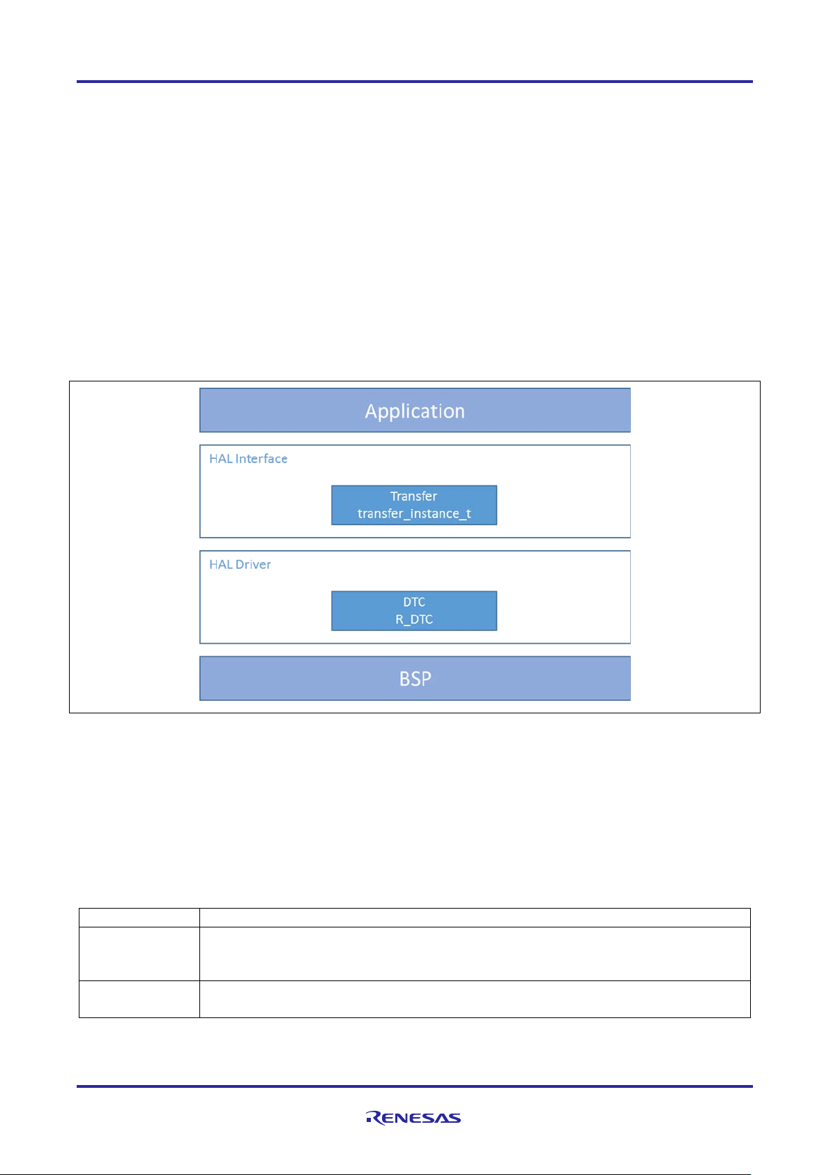
Figure 1. DTC HAL Module Block Diagram
2. DTC HAL Module APIs Overview
The DTC HAL module defines APIs for opening, closi ng, reset, enabling, disabling, starting, and stopping.
The DTC and the DMAC use the same transfer inte rf ace t o m ake it easier to change between DTC and DMA
implementations. The API calls are the same, independent of the lower-level implementations. A complet e
list of the available APIs, an example API call, and a short description of each can be found in the table
below. A table of status return values follows the A PI summary table.
Table 1. DTC HAL Module API Summary
Initial configuration. Enables the transfer if aut o_enable is true and p_src, p_dest, and
R11AN0116EU0101 Rev.1.01 Page 2 of 12
Jan.07.19
Page 3
Renesas Synergy™ Platform DTC HAL Module Guide
Function Name
Example API Call and Description
.reset
g_transfer0.api->reset(g_transfer0.p_ctrl, &source,
other settings the same. Enable the transfer if p_src, p_dest, and length are valid.
.start
g_transfer0.api->start(g_transfer0.p_ctrl, mode)
.stop
g_transfer0.api->stop(g_transfer0.p_ctrl)
Stop transfer in software. The transfer stops after completion of the current transfer.
.enable
g_transfer0.api->enable(g_transfer0.p_ctrl)
.disable
g_transfer0.api->disable(g_transfer0.p_ctrl)
transfer_info_t::activation_source).
.versionGet
g_transfer0.api->versionGet(&version)
.infoGet
g_transfer0.api->infoGet(g_transfer0.p_ctrl, &info)
Provides information about this transfer.
.blockReset
g_transfer0.api->blockReset(g_transfer0.p_ctrl, &source,
Name
Description
SSP_SUCCESS
API Call Successful.
SSP_ERR_ASSERTION
Parameter has invalid value.
SSP_ERR_NOT_OPEN
The channel is not opened.
SSP_ERR_UNSUPPORTED
Operation not configured correctly.
SSP_ERR_IN_USE
The channel specified has already been opened. No configurations
Control commands to reconfigure the channel .
SSP_ERR_HW_LOCKED
The DTC hardware resource is locked.
SSP_ERR_IRQ_BSP_DISABLED
IRQ not enabled in BSP.
SSP_ERR_NOT_ENABLED
Operation failed.
SSP_ERR_NOT_OPEN
The channel is not opened.
&destination, number_of_transfers)
Reset source address pointer, destination address pointer, and/or length, keeping all
Start transfer in software.
Enable transfer. Transfers occur after the activ at i on source event (or when start is
called if ELC_EVENT_ELC_SOFTWARE_EVENT_0 or
ELC_EVENT_ELC_SOFTWARE_EVENT_0 is ch osen as activation source).
Disable transfer. Transfers do not occur after the t ransfer_info_t::activation source
event (or when start is called if ELC_EVENT_ELC_SOFTWARE_EVENT_0 or
ELC_EVENT_ELC_SOFTWARE_EVENT_0 is chosen as
Gets version and stores it in provided pointer version.
&destination, length, size, number_of_transfers)
Reset source address pointer, destination address pointer, and/or length, for block
transfer keeping all other settings the same. E nabl e the transfer if p_src, p_dest, and
length are valid.
Note: For details on operation and definitions for the function data structures, typedefs, defines, API data,
API structures and function variables, review the SSP User’s Manual A PI References for the
associated module.
Table 2. Status Return Values
were changed. Call the associated Close function or use associated
Note: Lower-level drivers may return common error codes. Refer to the SSP User’s Manual API references
for the associated module for a definition of all relevant status return values.
3. DTC HAL Module Operational Overview
The Direct Memory Access Controller (DMAC) and the Data Transfer Controller (DTC) can be used t o m ove
data within the Synergy MCU. There are some consi derat ions when selecting between these
implementations. This section includes information on each to help you determine which implementation is
best for your application. The DTC module is recommended for most generic transfer applications, but either
module can be used for basic transfer functionalit y. The following use-cases for each transfer module are
given.
R11AN0116EU0101 Rev.1.01 Page 3 of 12
Jan.07.19
Page 4

Renesas Synergy™ Platform DTC HAL Module Guide
Selecting the DTC HAL Module
The DTC HAL module uses a RAM-based vector table with slots for every interrupt in the system. When the
DTC transfer completes, the activation source interrupt is called. To use the DTC, the activation source
interrupt must be enabled. Generally, the activat i on source interrupt is muted by the DTC until the transfer
completes unless TRANSFER_IRQ_EACH i s specified in the configuration. For example, if a normal-mode
transfer with a length of 16 is triggered by a timer, the timer interrupt does not fire the first 15 times while the
th
transfer is in effect. After the 16
transfer, the timer interrupt fires. DTC can also allow chained transfers,
meaning more than one transfer can occur after a single act ivation-source interrupt. This feature is supported
by the driver but must be configured outside the ISDE.
Selecting the DMAC HAL Module
The DMAC HAL module moves data from a user-specified source to a user-specified destination when an
interrupt or event occurs. The DMAC HAL module us es the DMAC peripheral registers, so the number of
transfers in the system is limited to the number of DM AC channels on the device. The activation source do es
not have to be enabled to use the DMAC. When the DMAC transfer completes, a DMAC interrupt is called. If
the activation source interrupt is enabled, it fires at the same time the transfer is triggered. If the DMAC
interrupt is enabled, it fires after all transfers are complete. For example, if a normal-mode transfer with a
length of 16 is triggered by a timer, the timer interrupt fires at the same time each transfer occurs and the
th
DMAC interrupt fires after the 16
transfer completes. The DMAC HAL module does not support chained
transfers.
3.1 DTC HAL Module Operational Notes
Normal Mode
In normal mode, a single transfer is triggered each tim e an act ivation-source event occurs. A single transfer
is 1 byte, 2 bytes, or 4 bytes, depending on the setting selected in the size parameter. Each time a transf er
occurs, the transfer length is decremented by 1. When the transfer length reaches 0, the transfer is
complete.
Repeat Mode
In repeat mode, a single transfer is triggered each ti me an act i vation-source event occurs. A single transfe r is
1 byte, 2 bytes, or 4 bytes, depending on the setting s el ect ed in the size parameter. Each time a transfer
occurs, the transfer length is decremented by 1. When the transfer length reaches 0, the transfer length is
reloaded with its initial value and the transfer re st arts. If the repeat area is set to source, the source register
is also reloaded with its initial value when the transf er restarts. Alternatively, if the repeat area is set t o
destination, the destination register is reloaded with its initial value when the transfer restart s.
Block Mode
In the block mode, the entire transfer length is transferred each time an activation-source event occurs. For
example, if a transfer is configured in block mode with the timer as the activation source, a 2-byte size, and a
12-byte length, 24 bytes are transferred each time t he act ivation source event occurs. Each time a transfer
occurs, the transfer length is decremented by 1. When the transfer length reaches 0, the transfer length is
reloaded with its initial value and the transfer re st arts. If the repeat area is set to source, the source register
is also reloaded with its initial value when the transf er restarts. Alternatively, if the repeat area is set to
destination, the destination register is reloaded with its initial value when the transfer restart s.
Address Mode
After each transfer of size (1 byte, 2 bytes, or 4 bytes), the source pointer and destination pointer are
adjusted by src_addr_mode and dest_addr_mode, respectively. For example, if src_addr_mode i s se t
to TRANSFER_ADDR_MODE_INCREMENTED and size is set to TRANSFER_SIZE_4_BYTES, the
p_dest pointer is incremented by 4 (the transfer size) after each transfer. The pointer does not change if s et
to TRANSFER_ADDR_MODE_FIXED.
Chained Transfers
Chained transfers are only supported by the DTC. To use a chained transfer, create an array of
transfer_info_t structures. Set chain_mode to TRANSFER_CHAIN_MODE_ENABLED for all
transfers except the last transfer. Set p_info to t he base of the first structure in the array for
transfer_info_t structures.
R11AN0116EU0101 Rev.1.01 Page 4 of 12
Jan.07.19
Page 5

Renesas Synergy™ Platform DTC HAL Module Guide
Resource
ISDE Tab
Stacks Selection Sequence
g_ transfer0 DTC Driver on r_dtc
Threads > HAL/Common
New Stack > Driver > Transfer > Transfer
3.2 DTC HAL Module Limitations
Refer to the most recent SSP Release Notes fo r any additional operational limitations for this module.
4. Including the DTC HAL Module in an Application
This section describes how to include the DTC HAL module i n an application using the SSP configurator.
Note: This section assumes that you are familiar with creating a project, adding t hreads, adding a stack to a
thread, and configuring a block within the stack. If you are unfamiliar with any of these items, refer to
the first few chapters of the SSP User’s Manual to learn how to manage each of these important
steps in creating SSP-based applications.
To add the DTC Driver to an application, simply add i t to a thread using the stacks selection sequence
provided in the following table. (The default name for the Transfer Driver is g_transfer0. This name can
be changed in the associated Properties window.)
Table 3. DTC Driver Selection Sequence
Driver on r_dtc
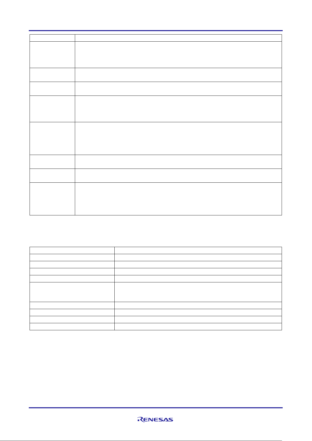
When the DTC HAL module on r_dtc is added to the thread stack as shown in the following figure, the
configurator automatically adds any needed lower-level modules. Any drivers that need additional
configuration information will be box text highlighte d in Red. Modul es with a Gray band are individual modules
that stand alone.
5. Configuring the DTC HAL Module
The DTC HAL module must be configured by the user for t he desired operation. The SSP configuration
window will automatically identify (by highlighting the block in red) any required configuratio n selections, such
as interrupts or operating modes, which must be configured for lower-level modules for successf ul operation.
Furthermore, only those properties that can be changed without causing conflicts are available f or
modification. Other properties are ‘locked’ and ar e unavailable to change, and these are identified with a l ock
icon for the ‘locked’ property in the ISDE Properties window. This approach simplifies the configuration
process and making it less error prone than previous ‘manual’ approaches t o configuration. The available
configuration settings and defaults for all the user ac cessible properties are given in the Properties tab in the
SSP configurator and are shown in the following tables f or easy reference.
One of the properties most often identified as requi ring a change is the interrupt priority; this configuration
setting is available within the Properties window of t he associated module. Simply select the indicated
module and then view the Properties window; the interrupt settings are often toward the bottom of the
properties list, so scroll down until they become available. Also, note that the interrupt priorities liste d i n the
Properties window in the ISDE will include an indication as to the validity of the setting based on the targeted
R11AN0116EU0101 Rev.1.01 Page 5 of 12
Jan.07.19
Figure 2. DTC HAL Module Stack
Page 6

Renesas Synergy™ Platform DTC HAL Module Guide
ISDE Property
Value
Description
Parameter
BSP, Enabled, Disabled
(Default: BSP)
Selects if code for parameter checking is to
Software Start
Disabled, Enabled
Selects if Software Start to be enabled
Linker section to
table
.ssp_dtc_vector_table
Section to place dtc vector table in
Name
g_transfer0
Module name.
Mode
Normal
Mode selection.
Transfer Size
1 Byte, 2 Bytes, 4 Bytes
Transfer size selection.
Destination
Fixed, Incremented, Decremented
(Default: Fixed)
Destination address mode selection.
Source Address
Fixed, Incremented, Decremented
Source address mode selection.
Repeat Area
Mode)
Source, Destination
Repeat area selection.
Interrupt Frequency
After all transfers have completed,
Defines when an interrupt occurs.
Destination Pointer
NULL
Destination pointer selection.
Source Pointer
NULL
Source pointer selection.
Number of
Transfers
0
Number of transfers selection.
Number of Blocks
0
Number of blocks selection.
Activation Source
The full list of interrupt activation
(Default: Software Activation 1)
Activation source selection.
Auto Enable
True, False
Auto enable selection.
Callback (Only
start)
NULL
Callback selection.
ELC Software
Priority 0 (highest),
Interrupt priority.
MCU (CM4 or CM0+). This level of detail is not included in the following configuration properties tables, but it
is easily visible with the ISDE when configuring interrupt-priority levels.
Note: You may want to open your ISDE, create the module and explore t he property settings in parallel with
looking over the configuration table settings give n below. This will help orient you and can be a useful
‘hands-on’ approach to learning the ins and outs of developing with SSP.
Table 4. Configuration Settings for the DTC HAL Module on r_dtc
Checking
keep DTC vector
Address Mode
Mode
(Unused in Normal
be included in the build.
(Default: Disabled)
(Default: 2 Bytes)
(Default: Fixed)
(Default: Source)
After each transfer
(Default: After all transfers have
completed)
(Valid only in Block
Mode)
(Must enable IRQ)
valid with Software
Event Interrupt
Priority
Note: The example values and defaults are for a project using the Synergy S7G2 MCU Family. Other MCU s
may have different default values and available configuration settings.
R11AN0116EU0101 Rev.1.01 Page 6 of 12
Jan.07.19
sources can be found in Table 14.4
of the MCU user manual.
(Default: True)
1,2,3,4,5,6,7,8,9,10,11,12,13,14,15
(lowest, not valid if using Thread X),
Disabled
(Default: Disabled)
Page 7

Renesas Synergy™ Platform DTC HAL Module Guide
Resource
Revision
Description
e2 studio
v6.2.0 or later
Integrated Solution Development Environment
SSP
v1.4.0 or later
Synergy Software™ Platform
IAR EW for Synergy
v8.21.1 or later
IAR Embedded Workbench® for Renesas Synergy™
SSC
v6.2.0 or later
Synergy Standalone Configurator
SK-S7G2
v3.0 to v3.1
Starter Kit
DTC HAL Module Clock Configuration
The DTC peripheral module uses ICLK as the clock s ource. The ICLK frequency is set by using the SSP
configurator Clocks tab prior to a build, or by using the CGC Interface at run-time.
DTC HAL Module Pin Configuration
The DTC is not associated with any pins.
6. Using the DTC HAL Module in an Application
The typical steps in using the DTC HAL module in an application are:
1. Initialize the DTC using the open API.
2. Enable the DTC using the enable API (if not auto ena bl ed).
3. Manage transfers using other APIs as needed.
4. Close the DTC when needed using the close API.
The following flow diagram illustrates common steps to using the DTC HAL mod ule are il lustrated:
Figure 3. Flow Diagram of a Typical DTC HAL Module Application
7. The DTC HAL Module Applicati on Project
The application project associated with this module guide demonstrates the given steps in a full design. The
project can be found using the link provided in the References section at the end of this document. You may
want to import and open the application project withi n the ISDE and view the configuration settings for the
DTC HAL module. You can also read over the code (DTC_HAL_MG_AP.c) use d t o il l ust rat e the DTC HAL
module APIs in a complete design. The following tabl e shows the software and hardware resources required
for the application project.
Table 5. Software and Hardware Resources Used by the Application Project
R11AN0116EU0101 Rev.1.01 Page 7 of 12
Jan.07.19
Page 8

Renesas Synergy™ Platform DTC HAL Module Guide
A simple flow diagram of the application project is given in the following figure.
Figure 4. DTC HAL Module Application Project Flow Diagram
The DTC_HAL_MG_AP.c file is in the project once it has been imported into the ISDE. You can open this file
within the ISDE and follow along with the descriptio n prov i ded to help identify key uses of APIs.
Two DTC instances will be used in this project:
g_transfer0 will be set up as a DTC HAL module in repeat mode
g_transfer1 will be set up as a DTC HAL module in normal mode
The first section of the file initializes two DTC HAL m odules, an ADC HAL module, and a timer module. The
timer module is set up to be a periodic 1s timer, and the ADC is set up to read the temperature sensor. The
DTC modules do not have to be enabled, as the Auto Enable option in the Synergy Configurator for DTC has
been enabled.
The DTC0 instance shows how to use the transfer module in repeat mode. The source address of the
transfer is set to the address of the ADTSDR (regi st er for storing the A/D conversion result of the
temperature sensor), and the destination addres s is set to the address of a destination variable,
destination_TemperatureVal. The file starts the ADC conversion. When the interr upt f or ADC0 Scan
End occurs, the transfer is activated. The transfer occurs without CPU intervention. At the end of each
interrupt, a transfer will occur. The Reset AP I does not have to be used to restart the transfer as DTC0 was
configured to be in the repeat mode.
The DTC1 instance shows how to use the transfer module in normal mode. The transfer is reset in the
Timer0 Overflow interrupt callback, timer_cb. The source address is set to the address of local variable
source_TimerVal. This holds the value of the number of timer interrupts. The destination address is set to the
address of a global destination_TimerVal variable. When the interrupt for Timer0 overflow occurs, a tran sfer
from the callback local variable to the global de st ination occurs without CPU intervention. A reset of the
transfer is done each time the interrupt occurs.
The last section of the application code is the user callback function for the ADC scan and timer overflow.
A few key properties of the application project are co nf i gured to support the required operations and the
physical properties of the target board and the MCU. The properties with the values set for thi s application
project are listed in the following table. You can also open the application project and view these settings in
the Properties window as a hands-on exercise.
R11AN0116EU0101 Rev.1.01 Page 8 of 12
Jan.07.19
Page 9

Renesas Synergy™ Platform DTC HAL Module Guide
ISDE Property
Value Set
Mode
Repeat
Transfer Size
2 Bytes
Activation Source
Event ADC0 Scan End
Interrupt Frequency
After each transfer
ISDE Property
Value Set
Mode
Normal
Transfer Size
1 Byte
Activation Source
Event GPT0 COUNTER OVERFLOW
Interrupt Frequency
After each transfer
Table 6. DTC0 Configuration Settings for the Application Project
Table 7. DTC1 Configuration Settings for the Application Project
8. Customizing the DTC HAL Module for a Target Application
Some configuration settings will normally be changed by the developer from those shown in the application
project. The user can easily change the configurati on settings for the DTC HAL module on r_dtc in the
Properties window. The user can select between t he 3 available modes: normal, repeat, and block mode.
The user can also select the preferred transfer size according to the application: 1, 2, or 4 bytes. The
Activation Source can also be selected.
9. Running the DTC HAL Module Application Project
To run the DTC HAL module application project and to see it executed on a target kit, you can simply import
it into your ISDE, compile, and run debug.
To implement the DTC HAL module application in a new project, follow the steps below for defining,
configuring, auto-generating files, adding cod e, compiling and debugging on the target kit. Following these
steps is a hands-on approach that can help make th e development process with SSP more practical, while
simply reading over this guide tends to be more theoretical.
To simply run the DTC HAL module application project, use t he following steps:
1. Refer to the Renesas Synergy Project Import Gui de (r11an0023eu0121-synergy-ssp-import-guide.pdf) for
instructions on importing the project into e
application.
2. Connect to the host PC through a micro USB cable to J19 on S K-S7G2.
3. Start to debug the application
4. The output can be viewed in the Expression window.
To create and run the DTC HAL module application project, use the following steps:
1. Create a new Renesas Synergy project for the SK-S7 G2 kit called DTC_HAL_MG_AP.
2. Add to HAL/Common, the DTC HAL modules, the ADC HAL module, and the timer module.
Refer the example projects configuration enclosed in the package for details.
3. Click the Generate Project content button.
4. Add the code from the supplied project files hal_entry.c, DTC_HAL_MG_AP.c, and
DTC_HAL_MG_AP.h.
5. Build the project.
6. Connect to the host PC via a micro USB cable to J19 on the SK-S7G2 board.
7. Start to debug the application.
8. The output can be viewed on the Renesas Virtual Debug Console (see Figure 5), or by adding variable
expressions to the watch view.
2
studio or IAR EW for Synergy, and building/running the
R11AN0116EU0101 Rev.1.01 Page 9 of 12
Jan.07.19
Page 10

Renesas Synergy™ Platform DTC HAL Module Guide
Figure 5. Example Output from the DTC HAL Module Application Project
10. DTC HAL Module Conclusion
This module guide has provided all the background information needed to select, add, configure an d use the
module in an example project. Many of these steps w ere t i m e-consuming and error-prone activities in
previous generations of embedded systems. T he Renesas Synergy Platform makes steps less timeconsuming and removes common errors (like co nflicting configuration settings or the incorrect selection of
low-level drivers). Using high-level APIs (as shown in the application project) illustrate the development time
saved in allowing work to begin at a high level, and avoids the time required in older development
environments to use or, in some cases, create lower-level drivers.
11. DTC HAL Module Next Steps
After you have mastered a simple DTC HAL module project, you may want to review a more complex
example. The touch slider application project for DK-S124 v3.0 with SSP 1.2.0 shows how to use the DTC in
a complete application. You can find this application project as described in the References section of t hi s
document.
12. DTC HAL Module Reference Information
SSP User Manual: Available in HTML format i n the SSP distribution package and as a pdf at the Synergy
Gallery (www.renesas.com/synergy/software).
Links to all the most up-to-date r_dtc module referenc e m aterials and resources are available on the Syner gy
Knowledge Base: https://en-support.renesas.com/search/r_dtc%20Module%20Guide%20Resources.
R11AN0116EU0101 Rev.1.01 Page 10 of 12
Jan.07.19
Page 11

Renesas Synergy™ Platform DTC HAL Module Guide
Website and Support
Visit the following vanity URLs to learn about key el ements of the Synergy Platform, download components
and related documentation, and get support.
Synergy Software www.renesas.com/synergy/software
Synergy Software Package www.renesas.com/synergy/ssp
Software add-ons www.renesas.com/synergy/addons
Software glossary www.renesas.com/synergy/softwareglossary
Development tools www.renesas.com/synergy/tools
Synergy Hardware www.renesas.com/synergy/hardware
Microcontrollers www.renesas.com/synergy/mcus
MCU glossary www.renesas.com/synergy/mcuglossary
Parametric search www.renesas.com/synergy/parametric
Kits www.renesas.com/synergy/kits
Synergy Solutions Gallery www.renesas.com/synergy/solutionsgallery
Partner projects www.renesas.com/synergy/partnerprojects
Application projects www.renesas.com/synergy/applicationprojects
Self-service support resources:
Documentation www.renesas.com/synergy/docs
Knowledgebase www.renesas.com/synergy/knowledgebase
Forums www.renesas.com/synergy/forum
Training www.renesas.com/synergy/training
Videos www.renesas.com/synergy/videos
Chat and web ticket www.renesas.com/synergy/resourcelibrary
R11AN0116EU0101 Rev.1.01 Page 11 of 12
Jan.07.19
Page 12

Renesas Synergy™ Platform DTC HAL Module Guide
Rev.
Date
Description
Page
Summary
1.00
Sep.01.17
–
Initial release
1.01
Jan.07.19
7
Updated Table 5 for SSP v1.5.0
Revision History
R11AN0116EU0101 Rev.1.01 Page 12 of 12
Jan.07.19
Page 13

Corporate Headquarters
Contact information
www.renesas.com
Trademarks
of their respective owners.
Notice
1. Descriptions of circuits, software and other related information in this document are provided only to illustrate the operation of semiconductor products
and application examples. You are fully responsible for the incorporation or any other use of the circuits, software, and information in the design of your
product or system. Renesas Electronics disclaims any and all liability for any losses and damages incurred by you or third parties arising from the use
of these circuits, softw a r e, or information.
2. Renesas Electronics hereby expressly disclaims any warranties against and liability for infringement or any other claims involving patents, copyrights,
or other intellectual property rights of third parties, by or arising from the use of Renesas Electronics products or technical information described in this
document, including but not limited to, the product data, drawings, charts, programs, algorithms, and application examples.
3. No license, express, implied or otherwise, is granted hereby under any patents, copyrights or other intellectual property rights of Renesas Electronics
or others.
4. You shall not alter, modify, copy, or reverse engineer any Renesas Electronics product, whether in whole or in part. Renesas Electronics disclaims any
and all liability for any losses or damages incurred by you or third parties arising from such alteration, modification, copying or reverse engineering.
5. Renesas Electronics products are classified according to the following two quality grades: “Standard” and “High Quality”. The intended applications for
each Renesas Electronics product depends on the product’s quality grade, as indicated below.
"Standard": Computers; office equipment; communications equipment; test and measurement equipment; audio and visual equipment; home
"High Quality": Transportation equipment (automobiles, trains, ships, etc.); traffic control (traffic lights); large-scale communication equipment; key
Unless expressly designated as a high reliability product or a product for harsh environments in a Renesas Electronics data sheet or other Renesas
Electronics document, Renesas Electronics products are not intended or authorized for use in products or systems that may pose a direct threat to
human life or bodily injury (artificial life support devices or systems; surgical implantations; etc.), or may cause serious property damage (space
system; undersea repeaters; nuclear power control systems; aircraft control systems; key plant systems; military equipment; etc.). Renesas Electronics
disclaims any and all liability for any damages or losses incurred by you or any third parties arising from the use of any Renesas Electronics product
that is inconsistent with any Renesas Electronics data sheet, user’s manual or other Renesas Electronics document.
6. When using Renesas Electronics products, refer to the latest product information (data sheets, user’s manuals, application notes, “General Notes for
Handling and Using Semiconductor Devices” in the reliability handbook, etc.), and ensure that usage conditions are within the ranges specified by
Renesas Electronics with respect to maximum ratings, operating power supply voltage range, heat dissipation characteristics, installation, etc. Renesas
Electronics disclaims any and all liability for any malfunctions, failure or accident arising out of the use of Renesas Electronics products outside of such
specified ranges.
7. Although Renesas Electronics endeavors to improve the quality and reliability of Renesas Electronics products, semiconductor products have specific
characteristics, such as the occurrence of failure at a certain rate and malfunctions under certain use conditions. Unless designated as a high reliability
product or a product for harsh environments in a Renesas Electronics data sheet or other Renesas Electronics document, Renesas Electronics
products are not subject to radiation resistance design. You are responsible for implementing safety measures to guard against the possibility of bodily
injury, injury or damage caused by fire, and/or danger to the public in the event of a failure or malfunction of Renesas Electronics products, such as
safety design for hardware and software, including but not limited to redundancy, fire control and malfunction prevention, appropriate treatment for
aging degradation or any other appropriate measures. Because the evaluation of microcomputer software alone is very difficult and impractical, you are
responsible for evaluating the safety of the final products or systems manufactured by you.
8. Please contact a Renesas Electronics sales office for details as to environmental matters such as the environmental compatibility of each Renesas
Electronics product. You are responsible for carefully and sufficiently investigating applicable laws and regulations that regulate the inclusion or use of
controlled substances, including without limitation, the EU RoHS Directive, and using Renesas Electronics products in compliance with all these
applicable laws and regulations. Renesas Electronics disclaims any and all liability for damages or losses occurring as a result of your noncompliance
with applicable laws and regulations.
9. Renesas Electronics products and technologies shall not be used for or incorporated into any products or systems whose manufacture, use, or sale is
prohibited under any applicable domestic or foreign laws or regulations. You shall comply with any applicable export control laws and regulations
promulgated and administered by the governments of any countries asserting jurisdiction over the parties or transactions.
10. It is the responsibility of the buyer or distributor of Renesas Electronics products, or any other party who distributes, disposes of, or otherwise sells or
transfers the product to a third party, to notify such third party in advance of the contents and conditions set forth in this document.
11. This document shall not be reprinted, reproduced or duplicated in any form, in whole or in part, without prior written consent of Renesas Electronics.
12. Please contact a Renesas Electronics sales office if you have any questions regarding the information contained in this document or Renesas
Electronics products.
(Note1) “Renesas Electronics” as used in this document means Renesas Electronics Corporation and also includes its directly or indirectly controlled
(Note2) “Renesas Electronics product(s)” means any product developed or manufactured by or for Renesas Electronics.
subsidiaries.
electronic appliances; machine tools; personal electronic equipment; industrial robots; etc.
financial terminal systems; safety control equipment; etc.
(Rev.4.0-1 November 2017)
TOYOSU FORESIA, 3-2-24 Toyosu,
Koto-ku, Tokyo 135-0061, Japan
Renesas and the Renesas logo are trademarks of Renesas Electronics
Corporation. All trademarks and registered trademarks are the property
For further information on a product, technology, the most up-to-date
version of a document, or your nearest sales office, please visit:
www.renesas.com/contact/.
© 2019 Renesas Electronics Corporation. All rights reserved.
 Loading...