

Page 1
RENAULT TRUCKS
Société Anonyme au capital de 50 000 000 €
Siège social : 99, route de Lyon
69802 Saint-Priest
Siret 954 506 077 00 120 - RCS LYON B 954 506 077
NE 1/ 3926 GB
RENAULT PREMIUM
DXi 11
330 - 380 - 440
50 21 022 931 - 06/2005
english edition
Contents
Chapter
FOREWORD. . . . . . . . . . . . . . . . . . . . . . . . . . . . . . . . .A
PRESENTATION . . . . . . . . . . . . . . . . . . . . . . . . . . . . .B
Vehicle access and protection. . . . . . . . . . . . . . . . . . . . . . . . . . . . . . . . . . . . . . . . . . . . . . . . . . . . . . . . . . . . . . . . . . . . . . . . . . . . . . . . . . . . . . . . . . . . . . . . . . . . . . . . . . . . . . . . . . . . . . . . . . . . . . . . . . . . . . . . . . . . . . . . . . . . . . . . . . . . . . . . . . . . . . . . . . . B1Driving position. . . . . . . . . . . . . . . . . . . . . . . . . . . . . . . . . . . . . . . . . . . . . . . . . . . . . . . . . . . . . . . . . . . . . . . . . . . . . . . . . . . . . . . . . . . . . . . . . . . . . . . . . . . . . . . . . . . . . . . . . . . . . . . . . . . . . . . . . . . . . . . . . . . . . . . . . . . . . . . . . . . . . . . . . . . . . . . . . . . . . . B2Safety . . . . . . . . . . . . . . . . . . . . . . . . . . . . . . . . . . . . . . . . . . . . . . . . . . . . . . . . . . . . . . . . . . . . . . . . . . . . . . . . . . . . . . . . . . . . . . . . . . . . . . . . . . . . . . . . . . . . . . . . . . . . . . . . . . . . . . . . . . . . . . . . . . . . . . . . . . . . . . . . . . . . . . . . . . . . . . . . . . . . . . . . . . . . . . B3
DRIVING . . . . . . . . . . . . . . . . . . . . . . . . . . . . . . . . . . . .C
Special conditions . . . . . . . . . . . . . . . . . . . . . . . . . . . . . . . . . . . . . . . . . . . . . . . . . . . . . . . . . . . . . . . . . . . . . . . . . . . . . . . . . . . . . . . . . . . . . . . . . . . . . . . . . . . . . . . . . . . . . . . . . . . . . . . . . . . . . . . . . . . . . . . . . . . . . . . . . . . . . . . . . . . . . . . . . . . . . . . . . . . . C1Prior to starting. . . . . . . . . . . . . . . . . . . . . . . . . . . . . . . . . . . . . . . . . . . . . . . . . . . . . . . . . . . . . . . . . . . . . . . . . . . . . . . . . . . . . . . . . . . . . . . . . . . . . . . . . . . . . . . . . . . . . . . . . . . . . . . . . . . . . . . . . . . . . . . . . . . . . . . . . . . . . . . . . . . . . . . . . . . . . . . . . . . . . . C2Start-up . . . . . . . . . . . . . . . . . . . . . . . . . . . . . . . . . . . . . . . . . . . . . . . . . . . . . . . . . . . . . . . . . . . . . . . . . . . . . . . . . . . . . . . . . . . . . . . . . . . . . . . . . . . . . . . . . . . . . . . . . . . . . . . . . . . . . . . . . . . . . . . . . . . . . . . . . . . . . . . . . . . . . . . . . . . . . . . . . . . . . . . . . . . . C3On the road . . . . . . . . . . . . . . . . . . . . . . . . . . . . . . . . . . . . . . . . . . . . . . . . . . . . . . . . . . . . . . . . . . . . . . . . . . . . . . . . . . . . . . . . . . . . . . . . . . . . . . . . . . . . . . . . . . . . . . . . . . . . . . . . . . . . . . . . . . . . . . . . . . . . . . . . . . . . . . . . . . . . . . . . . . . . . . . . . . . . . . . . . C4Stopping . . . . . . . . . . . . . . . . . . . . . . . . . . . . . . . . . . . . . . . . . . . . . . . . . . . . . . . . . . . . . . . . . . . . . . . . . . . . . . . . . . . . . . . . . . . . . . . . . . . . . . . . . . . . . . . . . . . . . . . . . . . . . . . . . . . . . . . . . . . . . . . . . . . . . . . . . . . . . . . . . . . . . . . . . . . . . . . . . . . . . . . . . . . . C5Driving on difficult ter rain . . . . . . . . . . . . . . . . . . . . . . . . . . . . . . . . . . . . . . . . . . . . . . . . . . . . . . . . . . . . . . . . . . . . . . . . . . . . . . . . . . . . . . . . . . . . . . . . . . . . . . . . . . . . . . . . . . . . . . . . . . . . . . . . . . . . . . . . . . . . . . . . . . . . . . . . . . . . . . . . . . . . . . . . . . . . C6
USE OF THE EQUIPMENT . . . . . . . . . . . . . . . . . . . .D
Trade equipment. . . . . . . . . . . . . . . . . . . . . . . . . . . . . . . . . . . . . . . . . . . . . . . . . . . . . . . . . . . . . . . . . . . . . . . . . . . . . . . . . . . . . . . . . . . . . . . . . . . . . . . . . . . . . . . . . . . . . . . . . . . . . . . . . . . . . . . . . . . . . . . . . . . . . . . . . . . . . . . . . . . . . . . . . . . . . . . . . . . . . D1Monitoring / manageme nt equipment . . . . . . . . . . . . . . . . . . . . . . . . . . . . . . . . . . . . . . . . . . . . . . . . . . . . . . . . . . . . . . . . . . . . . . . . . . . . . . . . . . . . . . . . . . . . . . . . . . . . . . . . . . . . . . . . . . . . . . . . . . . . . . . . . . . . . . . . . . . . . . . . . . . . . . . . . . . . . . . . . . . D2
FEATURES - SERVICING . . . . . . . . . . . . . . . . . . . . .E
Identification . . . . . . . . . . . . . . . . . . . . . . . . . . . . . . . . . . . . . . . . . . . . . . . . . . . . . . . . . . . . . . . . . . . . . . . . . . . . . . . . . . . . . . . . . . . . . . . . . . . . . . . . . . . . . . . . . . . . . . . . . . . . . . . . . . . . . . . . . . . . . . . . . . . . . . . . . . . . . . . . . . . . . . . . . . . . . . . . . . . . . . . . E1Daily checks. . . . . . . . . . . . . . . . . . . . . . . . . . . . . . . . . . . . . . . . . . . . . . . . . . . . . . . . . . . . . . . . . . . . . . . . . . . . . . . . . . . . . . . . . . . . . . . . . . . . . . . . . . . . . . . . . . . . . . . . . . . . . . . . . . . . . . . . . . . . . . . . . . . . . . . . . . . . . . . . . . . . . . . . . . . . . . . . . . . . . . . . . E2Routine servicing . . . . . . . . . . . . . . . . . . . . . . . . . . . . . . . . . . . . . . . . . . . . . . . . . . . . . . . . . . . . . . . . . . . . . . . . . . . . . . . . . . . . . . . . . . . . . . . . . . . . . . . . . . . . . . . . . . . . . . . . . . . . . . . . . . . . . . . . . . . . . . . . . . . . . . . . . . . . . . . . . . . . . . . . . . . . . . . . . . . . E3Maintenance instructio ns. . . . . . . . . . . . . . . . . . . . . . . . . . . . . . . . . . . . . . . . . . . . . . . . . . . . . . . . . . . . . . . . . . . . . . . . . . . . . . . . . . . . . . . . . . . . . . . . . . . . . . . . . . . . . . . . . . . . . . . . . . . . . . . . . . . . . . . . . . . . . . . . . . . . . . . . . . . . . . . . . . . . . . . . . . . . . . E4Servicing intervals . . . . . . . . . . . . . . . . . . . . . . . . . . . . . . . . . . . . . . . . . . . . . . . . . . . . . . . . . . . . . . . . . . . . . . . . . . . . . . . . . . . . . . . . . . . . . . . . . . . . . . . . . . . . . . . . . . . . . . . . . . . . . . . . . . . . . . . . . . . . . . . . . . . . . . . . . . . . . . . . . . . . . . . . . . . . . . . . . . . E5Engine . . . . . . . . . . . . . . . . . . . . . . . . . . . . . . . . . . . . . . . . . . . . . . . . . . . . . . . . . . . . . . . . . . . . . . . . . . . . . . . . . . . . . . . . . . . . . . . . . . . . . . . . . . . . . . . . . . . . . . . . . . . . . . . . . . . . . . . . . . . . . . . . . . . . . . . . . . . . . . . . . . . . . . . . . . . . . . . . . . . . . . . . . . . . . E6Engine cooling . . . . . . . . . . . . . . . . . . . . . . . . . . . . . . . . . . . . . . . . . . . . . . . . . . . . . . . . . . . . . . . . . . . . . . . . . . . . . . . . . . . . . . . . . . . . . . . . . . . . . . . . . . . . . . . . . . . . . . . . . . . . . . . . . . . . . . . . . . . . . . . . . . . . . . . . . . . . . . . . . . . . . . . . . . . . . . . . . . . . . . . E7Fuel system . . . . . . . . . . . . . . . . . . . . . . . . . . . . . . . . . . . . . . . . . . . . . . . . . . . . . . . . . . . . . . . . . . . . . . . . . . . . . . . . . . . . . . . . . . . . . . . . . . . . . . . . . . . . . . . . . . . . . . . . . . . . . . . . . . . . . . . . . . . . . . . . . . . . . . . . . . . . . . . . . . . . . . . . . . . . . . . . . . . . . . . . . E8Clutch. . . . . . . . . . . . . . . . . . . . . . . . . . . . . . . . . . . . . . . . . . . . . . . . . . . . . . . . . . . . . . . . . . . . . . . . . . . . . . . . . . . . . . . . . . . . . . . . . . . . . . . . . . . . . . . . . . . . . . . . . . . . . . . . . . . . . . . . . . . . . . . . . . . . . . . . . . . . . . . . . . . . . . . . . . . . . . . . . . . . . . . . . . . . . . E9Gearbox. . . . . . . . . . . . . . . . . . . . . . . . . . . . . . . . . . . . . . . . . . . . . . . . . . . . . . . . . . . . . . . . . . . . . . . . . . . . . . . . . . . . . . . . . . . . . . . . . . . . . . . . . . . . . . . . . . . . . . . . . . . . . . . . . . . . . . . . . . . . . . . . . . . . . . . . . . . . . . . . . . . . . . . . . . . . . . . . . . . . . . . . . . . E10Hydraulic retarder . . . . . . . . . . . . . . . . . . . . . . . . . . . . . . . . . . . . . . . . . . . . . . . . . . . . . . . . . . . . . . . . . . . . . . . . . . . . . . . . . . . . . . . . . . . . . . . . . . . . . . . . . . . . . . . . . . . . . . . . . . . . . . . . . . . . . . . . . . . . . . . . . . . . . . . . . . . . . . . . . . . . . . . . . . . . . . . . . . E11Power take-off. . . . . . . . . . . . . . . . . . . . . . . . . . . . . . . . . . . . . . . . . . . . . . . . . . . . . . . . . . . . . . . . . . . . . . . . . . . . . . . . . . . . . . . . . . . . . . . . . . . . . . . . . . . . . . . . . . . . . . . . . . . . . . . . . . . . . . . . . . . . . . . . . . . . . . . . . . . . . . . . . . . . . . . . . . . . . . . . . . . . . . E12Prop shaft. . . . . . . . . . . . . . . . . . . . . . . . . . . . . . . . . . . . . . . . . . . . . . . . . . . . . . . . . . . . . . . . . . . . . . . . . . . . . . . . . . . . . . . . . . . . . . . . . . . . . . . . . . . . . . . . . . . . . . . . . . . . . . . . . . . . . . . . . . . . . . . . . . . . . . . . . . . . . . . . . . . . . . . . . . . . . . . . . . . . . . . . . . E13Axle. . . . . . . . . . . . . . . . . . . . . . . . . . . . . . . . . . . . . . . . . . . . . . . . . . . . . . . . . . . . . . . . . . . . . . . . . . . . . . . . . . . . . . . . . . . . . . . . . . . . . . . . . . . . . . . . . . . . . . . . . . . . . . . . . . . . . . . . . . . . . . . . . . . . . . . . . . . . . . . . . . . . . . . . . . . . . . . . . . . . . . . . . . . . . . . E14Rear drive axle . . . . . . . . . . . . . . . . . . . . . . . . . . . . . . . . . . . . . . . . . . . . . . . . . . . . . . . . . . . . . . . . . . . . . . . . . . . . . . . . . . . . . . . . . . . . . . . . . . . . . . . . . . . . . . . . . . . . . . . . . . . . . . . . . . . . . . . . . . . . . . . . . . . . . . . . . . . . . . . . . . . . . . . . . . . . . . . . . . . . . E15Suspension systems . . . . . . . . . . . . . . . . . . . . . . . . . . . . . . . . . . . . . . . . . . . . . . . . . . . . . . . . . . . . . . . . . . . . . . . . . . . . . . . . . . . . . . . . . . . . . . . . . . . . . . . . . . . . . . . . . . . . . . . . . . . . . . . . . . . . . . . . . . . . . . . . . . . . . . . . . . . . . . . . . . . . . . . . . . . . . . . . . . E16Steering . . . . . . . . . . . . . . . . . . . . . . . . . . . . . . . . . . . . . . . . . . . . . . . . . . . . . . . . . . . . . . . . . . . . . . . . . . . . . . . . . . . . . . . . . . . . . . . . . . . . . . . . . . . . . . . . . . . . . . . . . . . . . . . . . . . . . . . . . . . . . . . . . . . . . . . . . . . . . . . . . . . . . . . . . . . . . . . . . . . . . . . . . . . E17Cab tilting . . . . . . . . . . . . . . . . . . . . . . . . . . . . . . . . . . . . . . . . . . . . . . . . . . . . . . . . . . . . . . . . . . . . . . . . . . . . . . . . . . . . . . . . . . . . . . . . . . . . . . . . . . . . . . . . . . . . . . . . . . . . . . . . . . . . . . . . . . . . . . . . . . . . . . . . . . . . . . . . . . . . . . . . . . . . . . . . . . . . . . . . . E18Brakes . . . . . . . . . . . . . . . . . . . . . . . . . . . . . . . . . . . . . . . . . . . . . . . . . . . . . . . . . . . . . . . . . . . . . . . . . . . . . . . . . . . . . . . . . . . . . . . . . . . . . . . . . . . . . . . . . . . . . . . . . . . . . . . . . . . . . . . . . . . . . . . . . . . . . . . . . . . . . . . . . . . . . . . . . . . . . . . . . . . . . . . . . . . . E19Roadwheels / Tyres . . . . . . . . . . . . . . . . . . . . . . . . . . . . . . . . . . . . . . . . . . . . . . . . . . . . . . . . . . . . . . . . . . . . . . . . . . . . . . . . . . . . . . . . . . . . . . . . . . . . . . . . . . . . . . . . . . . . . . . . . . . . . . . . . . . . . . . . . . . . . . . . . . . . . . . . . . . . . . . . . . . . . . . . . . . . . . . . . . E20Heating / Air conditioning . . . . . . . . . . . . . . . . . . . . . . . . . . . . . . . . . . . . . . . . . . . . . . . . . . . . . . . . . . . . . . . . . . . . . . . . . . . . . . . . . . . . . . . . . . . . . . . . . . . . . . . . . . . . . . . . . . . . . . . . . . . . . . . . . . . . . . . . . . . . . . . . . . . . . . . . . . . . . . . . . . . . . . . . . . . . E21Independent heating . . . . . . . . . . . . . . . . . . . . . . . . . . . . . . . . . . . . . . . . . . . . . . . . . . . . . . . . . . . . . . . . . . . . . . . . . . . . . . . . . . . . . . . . . . . . . . . . . . . . . . . . . . . . . . . . . . . . . . . . . . . . . . . . . . . . . . . . . . . . . . . . . . . . . . . . . . . . . . . . . . . . . . . . . . . . . . . . . E22Batteries. . . . . . . . . . . . . . . . . . . . . . . . . . . . . . . . . . . . . . . . . . . . . . . . . . . . . . . . . . . . . . . . . . . . . . . . . . . . . . . . . . . . . . . . . . . . . . . . . . . . . . . . . . . . . . . . . . . . . . . . . . . . . . . . . . . . . . . . . . . . . . . . . . . . . . . . . . . . . . . . . . . . . . . . . . . . . . . . . . . . . . . . . . . E23Alternator . . . . . . . . . . . . . . . . . . . . . . . . . . . . . . . . . . . . . . . . . . . . . . . . . . . . . . . . . . . . . . . . . . . . . . . . . . . . . . . . . . . . . . . . . . . . . . . . . . . . . . . . . . . . . . . . . . . . . . . . . . . . . . . . . . . . . . . . . . . . . . . . . . . . . . . . . . . . . . . . . . . . . . . . . . . . . . . . . . . . . . . . . E24Starter . . . . . . . . . . . . . . . . . . . . . . . . . . . . . . . . . . . . . . . . . . . . . . . . . . . . . . . . . . . . . . . . . . . . . . . . . . . . . . . . . . . . . . . . . . . . . . . . . . . . . . . . . . . . . . . . . . . . . . . . . . . . . . . . . . . . . . . . . . . . . . . . . . . . . . . . . . . . . . . . . . . . . . . . . . . . . . . . . . . . . . . . . . . . E25Compressed air system. . . . . . . . . . . . . . . . . . . . . . . . . . . . . . . . . . . . . . . . . . . . . . . . . . . . . . . . . . . . . . . . . . . . . . . . . . . . . . . . . . . . . . . . . . . . . . . . . . . . . . . . . . . . . . . . . . . . . . . . . . . . . . . . . . . . . . . . . . . . . . . . . . . . . . . . . . . . . . . . . . . . . . . . . . . . . . . E26Fifth wheel coupling . . . . . . . . . . . . . . . . . . . . . . . . . . . . . . . . . . . . . . . . . . . . . . . . . . . . . . . . . . . . . . . . . . . . . . . . . . . . . . . . . . . . . . . . . . . . . . . . . . . . . . . . . . . . . . . . . . . . . . . . . . . . . . . . . . . . . . . . . . . . . . . . . . . . . . . . . . . . . . . . . . . . . . . . . . . . . . . . . E27Cleaning. . . . . . . . . . . . . . . . . . . . . . . . . . . . . . . . . . . . . . . . . . . . . . . . . . . . . . . . . . . . . . . . . . . . . . . . . . . . . . . . . . . . . . . . . . . . . . . . . . . . . . . . . . . . . . . . . . . . . . . . . . . . . . . . . . . . . . . . . . . . . . . . . . . . . . . . . . . . . . . . . . . . . . . . . . . . . . . . . . . . . . . . . . . E28
QUICK BREAKDOWN REPAIR . . . . . . . . . . . . . . . .F
BODYBUILDER INFORMATION . . . . . . . . . . . . . .G
All manuals and user guides at all-guides.com
all-guides.com
Page 2

The manufacturer reserves the right to make any modifications deemed necessary during production. This handbook
should not be considered as a specification for the model in question.
© RENAULT TRUCKS SA - 2004 - Imprimé en France
All manuals and user guides at all-guides.com
Page 3
Alphabetical index
A
Accelerator pedal, C4-6
ADR vehicle (transport of dangerous
materials), B3-4, C5-3
Adjusting the steering wheel, B2-50
Advice, E20-6
Air filters, E6-6
Air tanks, E2-3, E26-2
Air vents, B2-60
Alarm, B1-9
Anti-slip regulator (ASR), C6-2
APM (Air Production Management) unit,
E26-1
Axle, steering maintenance operations,
E5-9
B
Beam height correction, E3-9
Bleeding the fuel system, E8-5
Bodywork, G-1
Brakes maintenance operations, E5-10
Brakes types, E19-1
Brake pads, E19-2
Brake valve, E26-1
"EBS" braking system, C4-42
Bulbs, E3-1
Bunks and storage compartments, B2-69
C
Cab overhead lights, B2-74
Cab tilting system oil capacity, E18-1
Cab tilting, B1-20, E18-1
Chassis, cab, electrics maintenance
operations, E5-11
Checking the oil level, E2-2, E6-3
Child safety, B3-2
Circuit capacity, E9-1
Cleaning the cockpit, E28-2
Cleaning the fascia panel, E28-2
Cleaning the headlamps, E28-2
Cleaning the seats, E28-2
Clutch fluid level, E2-1
Clutch system, E9-2
Clutch types, E9-1
Clutch, gearbox, power take-off
maintenance operations, E5-8
Combined lights and horn switch, B2-47
Coolant level, E2-1
Coolant, E7-1
Cruise control, C4-3
D
Daily checks, E2-1
Dashboard, B2-6
Description of Optidriver 2, C4-29
Diagnostic socket, D2-1
Display test, C2-5
Doors, B1-2
Drive axle P 1395 A oil change, E15-2
Drive axle P13170 oil change, E15-1
Drive axle, prop shaft maintenance
operations, E5-9
"Rear drive axle(s)" diff. lock, C6-1
Driving a solo tractor, C1-3
Driving Monitoring System, C4-20
Driving on difficult terrain, C6-1
DXi 11, E6-2
E
Economic driving, C1-3
Electrically operated rearview mirrors,
B2-46
Electrically operated sun-roof, B2-53
Electric window raiser controls, B2-52
Electronic air suspension, D1-9
Electronic speed limiter, C4-6
Emergency brake, C4-49
Engine idling speed adjustment device,
C3-5
Engine immobilizer, C2-4
Engine maintenance operations, E5-6
Engine oil capacities, E6-2
Engine oil level gauge, C2-2
Engine operating speed, C4-2
Engine starting with pilot-controlled
starter feature, C3-3
"ESP" (electronic stability program)
system, C4-47
All manuals and user guides at all-guides.com
Page 4
Alphabetical index
Exhaust brake and exhaust brake
"OPTIBRAKE" (with Optidriver 2
gearbox), C4-12
Exhaust brake with engine brake
"OPTIBRAKE" (with manual gearbox),
C4-10
Exhaust brake with engine brake
"OPTIBRAKE" coupled with a VOITH
hydraulic retarder (with Optidriver 2
gearbox), C4-14
Exhaust brake with or without engine
brake "OPTIBRAKE" coupled with a ZF
hydraulic retarder (with ZF gearbox),
C4-18
Exhaust brake (with manual gearbox),
C4-9
External storage locker(s), B1-23
F
Fall-back mode (lever disconnected),
C4-40
Fan-coil heater filter, E21-2
Fast idling device, C3-6
Fault display, C2-6
Fifth wheel coupling, D1-2
"FONTAINE" sliding fifth wheel
coupling, D1-8
"GEORG FISCHER" fifth wheel
coupling, D1-4
"JOST" fifth wheel coupling, D1-5
"JOST" 42 fifth wheel coupling, D1-6
Fifth wheel types, E27-1
Filling the engine cooling system, E7-6
Filter cartridge replacement, E17-1
Fire extinguisher, B3-3
First aid kit, B3-8
Front axle types, E14-1
Front axle, E14-1
Front grille, B1-17
Front suspension, E16-1
Fuel filter(s), E8-3
Fuel preheater, E8-8
Fuel tank capacities, E8-1
Fuel tank(s), B1-25, E8-6
Fuel, E4-3
Fuses, E3-10
G
Gearbox oil capacity, E10-2
Gearbox types, E10-1
ZF gearbox + Intarder oil change, E10-9
General usage instructions for
commercial vehicles, A-2
H
Headlamps wash reservoir, E2-5
Headlights adjustment, B2-49, E3-8
Heated windscreen, B2-46
Heating - Ventilation, B2-54
Heating, air conditioning maintenance
operations, E5-12
Hydraulic power-assisted steering, C4-1,
E17-3
I
Ignition switch, C2-5
Independent heating, B2-61
Infomax, D2-1
Inspection / lubrication, E27-1
Instrument panel, B2-10
International standards, E4-7
K
Keys, B1-1
Key to switches, B2-24
Key to warning pictograms, B2-16
Key to "gearbox" warning pictograms,
B2-21
Key to "tachograph" warning pictograms,
B2-22
L
Location of jack and onboard kit, F-2
Lubricants, E4-4
Lubrication diagram(s), E4-12
M
Maintenance display, C2-7
Maintenance, E16-1, E21-1
Master switch, B1-26
All manuals and user guides at all-guides.com
Page 5
Alphabetical index
"ADR" master switch (transport of
dangerous materials), B1-27
Monitoring / management equipment,
D2-1
Multi-function information display,
B2-28
O
Oil capacity, E15-1
Oil change, E6-4, E10-8
Oil filters, E6-4
Onboard radio, B2-74
Optidriver 2 gearbox oil change, E10-3
Optidriver 2 gearbox, C4-26, E4-7, E4-9
P
Parking brake, B2-51, C4-50
Power take-off types, E12-1
Power take-off, D1-20, D1-21, E4-9
Precautions, E19-1
Preheating the engine cooling system,
C1-4
Prior to getting into the vehicle, C2-1
Protecting diesel fuel against freezing and
additives, E8-7
R
Radiator mosquito net, E7-2
Rational use of batteries, E23-6
Rear drive axle types, E15-1
Rear suspension, D1-9, E16-1
Refrigerator, B2-71
Regulatory test display, C2-5
Remote control battery, E3-18
Remote control box, D1-10
Retarder types, E11-1
Retarder, C4-7
VOITH retarder oil change, E10-6
Reversing buzzer, C4-41
Roof air vent, B2-53
Roof deflector, D1-25
Routine servicing, E3-1
S
Seats, B2-1
Seat belts, B3-1
Servicing frequencies, E5-1
Servicing, E22-1
Side fairings, B1-18
Soundproofing screens and heat shields,
E6-1
Spare wheel carrier, F-4
Starter types, E25-1
Starting the engine, C3-1
Starting the vehicle using an external
power source, F-1
Steering types, E17-1
Stopping the engine, C5-1
Suspension maintenance operations,
E5-10
T
Test procedure, D1-19
Tightening the wheel nuts, E20-2, F-7
Towing, F-8
Trade equipment, D1-1
Trailer brake, C4-49
Turbocharger, E6-8
Tyres, E2-4
Tyre features, E20-1
Tyre pressures, E20-3
U
Use at high altitude, C1-2
Use during the summer or in hot climates,
C1-2
Use during the winter or in cold climates,
C1-1
Use in dusty atmospheres, C1-2
Use of the equipment, D1-1
Use on downhill runs, C4-37
Using the jack, F-5
V
Variable-drive cooling fan, E7-3
Vehicle identification, E1-1
4x2 vehicle with adjustable rear
suspension, D1-11
4x2 - 6x2 vehicle with adjustable rear
suspension, D1-13
All manuals and user guides at all-guides.com
Page 6

Alphabetical index
4x2 - 6x2 vehicle with integral
suspension, D1-17
W
Warranty, E4-1
Washing the body, E28-1
Washing the vehicle, E28-1
Welcome onboard your new RENAULT,
A-1
Welding on vehicle, G-1
Wheels, tyres maintenance operations,
E5-12
Wheel chocks, B3-3
Windscreen wash reservoir level, E2-4
Windscreen wiper, windscreen wash and
headlamps wash control, B2-49
Working spotlight (tractor), D1-1
All manuals and user guides at all-guides.com
all-guides.com
Page 7
A-1 Foreword
OREWORDWelcome onboard your new RENAULT
You have now taken possession of your new vehicle.
We trust that it will give you the entire satisfaction you have the right to expect and which
was the reason for your original choice.
This driving and servicing handbook has been laid out to provide all the information you
need and will enable you to:
– Get to know your Renault better and, on the same occasion, to derive the maximum of
benefit from all the technical perfections with which it is endowed, under the very best
working conditions.
– Permanently guarantee optimum operation by simply - but strictly - observing mainte-
nance recommendations.
– Cope with any minor malfunctions not requiring assistance from a specialist, without
losing too much time.
This handbook covers all the options proposed to customers.
Take into account only indications corresponding to the model in your possession.
The few moments devoted to reading this handbook will be well worthwhile on account of
the information it contains and the new technical features you will discover. If any details
remain unclear, our dealer staff will be pleased to provide you with any further information
you may require.
To read the text:
The reference numbers, figures and letters mentioned in the text refer back to two types of
illustration:
– Figures correspond to figures or photographs situated in proximity to the text.
– Letters, sometimes followed by a figure, correspond to the instrument panel diagram
to be found inside the handbook.
"Bon voyage" at the wheel of your Renault !
RENAULT TRUCKS: Frontier-free service
Renault Trucks 24/24 has been in operation for several years now.
19 emergency call centres are listening in for you 365 days a year .
Spare parts officially approved by RENAULT TRUCKS meet both the requirements of the
vehicle specification and the regulations in force. Only premium Renault parts will ensure:
– Original Equipment safety standards,
– Full Manufacturer's Warranty,
– Maintenance of original characteristics and performance.
All manuals and user guides at all-guides.com
Page 8
A-2 Foreword
General usage instructions for commercial vehicles
If you are a professional driver using your own vehicle, or a haulier entrusting one of your
vehicles to a member of your staff, it is essential to follow and ensure the application of the
following instructions. They are only a reminder of the basics of the trade and standard pro-
fessional practice and in no way are to be taken as exhaustive. In this way you will obtain
the maximum profit from your material and prevent any risk of accidents and incidents.
1. A few basic instructions
– Every driver must possess all necessary licences and should only drive when physical-
ly fit and sufficiently rested.
– The vehicle must be in conformity with current legislation in the country or countries
in which it is used.
– Any signs indicating hazardous substances must be affixed and be in good condition.
– Loads:
• All-up or per-axle weights (regulatory or technical) must not be exceeded.
• Loading and securing of loads must be carried out using conventional procedures,
tarpaulins and side curtains must be correctly stretched and fastened and doors and
sideboards locked, etc...
– In the cab:
• Never carry dangerous products (such as petroleum, trichlorethylene, thinner,
etc.).
• If an animal is carried, it must be kept away from the driving position.
– Getting in and out of the vehicle:
• Use the steps and the handles provided. Never jump down from the vehicle. When
leaving the vehicle, observe the traffic flow, particularly if you have been driving
for a long time.
• Take extra care when the climatic conditions are bad (rain, snow, ice) and at night.
– USE IN CLOSED PREMISES:
• NEVER LEAVE THE ENGINE RUNNING IN CLOSED OR POORLY VENTILATED
PREMISES. THE EXHAUST GASES CONTAINED EXTREMELY TOXIC CON-
STITUENTS. THEIR CONCENTRATION MAY HAVE VERY SERIOUS EFFECTS
ON YOUR HEALTH.
All manuals and user guides at all-guides.com
Page 9
A-3 Foreword
2. Before getting into the vehicle, check:
– General condition of your vehicle, visually (as per handbook);
– Tyre condition, tyre pressures (including the spare wheel), and that nothing is jammed
between the twin wheels;
– Cleanliness of cab windows, rearview mirrors, headlights and other lights and number
plates;
– Regulatory and optional lighting systems for correct operation;
– Semi-trailer and/or trailer for correct coupling (hook, brake hoses - colour coding -
electrical connector...);
– For the presence and contents of the onboard tool kit;
– In winter, for the presence of anti-skid chains and that they are securely fastened;
– Vehicles equipped with side guard panels and beams should be permanently provided
with this equipment. At the time of removal, make sure that the locks are correctly
locked and tighten the setscrews moderately.
3. In the cab
– Check the condition of the non-slip foot pedal covers.
– Ensure that the safety controls (steering wheel, foot pedals, gear lever etc...) are never
cleaned with a slippery product like silicone).
– Adjust your driving position:
• Steering wheel: check that the steering column is locked.
• Seat: check that the seat is firmly locked.
• Rearview mirrors.
• Seat belt: it is compulsory to wear one, so buckle up.
• Onboard children: comply with the laws in force.
– Before starting the engine: ensure that the gear lever is properly in neutral.
– Check that all instrument panel indications are normal (if you are not certain of what
the nominal readings are supposed to be, refer to the Driving & Servicing Handbook.
Analogue tachograph
– Check that the tachograph chart is in place in the tachograph unit and that the unit is
working properly.
Digital tachograph
– Check that the driver's tachograph chart 1 is in place in the tachograph tray.
If there is a 2
nd
driver, Check that his tachograph chart is in place in the tachograph
tray 2.
Check that the tachograph unit is working properly.
All manuals and user guides at all-guides.com
Page 10
A-4 Foreword
4. When driving
– If you detect any anomaly in the way the vehicle is operating, stop and locate the mal-
function.
Do not move off again until you are sure that the incident has not impaired technical
performance and safety.
– When driving, the use of some of the standard-fitted equipment, and other optional or
added equipment is strictly forbidden (i.e. hand-operated sun-roofs, television sets,
etc...) or only permitted if all necessary precautions are taken so as not to affect road
safety (cigar lighter, manual selection of radio stations, CB, onboard telephone...).
– Adapt your driving style to suit your load (cant or bend, if the centre of gravity is high,
etc...) to take account of weather conditions and the time of day.
If necessary, adjust the headlight beam levels.
– Never shut down the engine when the vehicle is moving (as this will cut off the supply
to the power-assisted steering system and could decrease brake effectiveness).
5. When parking
– Check that the vehicle is correctly parked (i.e. that it does not obstruct traffic flow or
threaten the security of neighbouring installations).
– If the vehicle is going to remain stationary for some time, use one or more wheel
chocks to prevent it from moving (e.g. semi-trailer compressed air leakage, or in black
ice conditions...).
– Check that:
• The parking brake is locked and immobilizes the road train or rig.
• The gear lever is in neutral.
• The battery isolating switch is open (turned off).
• The electromagnetic retarder is switched off.
• The air vents are not blocked (if an independent heater is used).
• The parking lights are switched on at night.
– Check that you have not left in the cab:
• important documents (personal, vehicle, load).
• unaccompanied animals.
All manuals and user guides at all-guides.com
Page 11
A-5 Foreword
6. When repairing / servicing the vehicle
Prior to carrying out any work on the electronic air suspension (other than
calibration), place axle stands under the chassis.
– Check the tightness of the wheel nuts according to recommendations.
– Prior to tilting the cab:
• Ensure there is enough necessary space available in front of the vehicle.
• Set the limits of a safety perimeter around the cab inside which you must pay
attention that nobody tries to cross that area or park in it, not only during the cab
tilting operations but also when the cab is fully tilted.
• Stop the engine, put the gear lever into neutral and make sure that no object is like-
ly to fall onto the windscreen. If a refrigerator is fitted, drain it. Close the doors.
• Tilt the cab as far as possible. If the cab is only partially tilted, wedge it to prevent
accidental movement.
– If the engine is running:
• Do not approach moving parts (fan, drive belts, etc...).
• Do not turn off the electrical power supply (shut down the engine first).
– When climbing up onto or down from the ramp behind the cab (tractor), use the steps
and grab handles provided. Never jump down from the ramp. Take care not to burn
yourself (on the vertical exhaust pipe and silencer).
– Fuel is inflammable: if the fuel filler cap is open, smoking is forbidden and there must
be no naked flame in the vicinity.
– Batteries are filled with acids, which can cause serious injuries. They must be handled
with great care.
– If you start the engine using an external power source:
• Use cables of the correct dimensions.
• Make sure that the + and - polarities are connected properly.
– When changing a fuse, it is vital to use another fuse of the same size.
– Only specialists should install additional power lines.
– The installation of additional air lines requires a technical study carried out or
approved by the manufacturer.
– It is strictly forbidden to heat polyamide hoses (braking circuit pipes).
– Raising the vehicle with a jack. chock the wheels prior to jacking.
– Immobilizing the vehicle: use one or several wheel chocks as necessary.
– Wheels and tyres:
• Never check tyre pressures or inflate or deflate a tyre, which is hot.
• Never stand in front of a tyre when checking the pressure or inflating it.
• When fitting a roadwheel, take great care to centre wheels fitted with centring
clamps (for trilex wheels, position the clamp at the segment crossover point).
All manuals and user guides at all-guides.com
all-guides.com
Page 12
A-6 Foreword
– Repairs on the open road: collect the fluids, which have been drained (such as oil, fuel,
coolant...).
– With an eye to environmental protection, take into consideration the laws in force
(recovery of oil / anti-freeze / cartridges).
When draining oils (engine / gearbox / drive axles), you run the risk of burning yourself (hot
oil).
When draining coolant, you run the risk of burning yourself (hot fluid).
– Independent heater: use motor vehicle diesel fuel only.
– If anti-skid chains are used, the rear wings should be removed, road speed should be
reduced and chain tension should be tested at regular intervals.
Any modification to circuits (electrical, electronic or compressed air) may have serious
consequences. Such work should only be undertaken in agreement with the manufac-
turer. RENAULT TRUCKS decline any responsibility in the event of non-conformity
in assembly.
Only genuine, original RENAULT TRUCKS parts and circuits defined by the manu-
facturer guarantee quality, safety and reliability.
By observing the above instructions, you will be using your vehicle in the best possible way.
However, you must also carefully read the driving handbook and consult the RENAULT
TRUCKS network whenever you need any further information.
We remind you that application of the contractual warranty by RENAULT TRUCKS is sub-
ject, among other things, to proof by the customer that servicing and maintenance of the ve-
hicle have been carried out according to our recommendations (frequency, operations to be
performed, quality of expendable and consumable products guaranteed by genuine certified
or recommended spare parts, quality and training of repair mechanics and use of specific
tools...). Observance of these recommendations will also guarantee long-term reliability of
the vehicle.
Servicing and maintenance conducted by the RENAULT TRUCKS network is a guarantee
of observance of these recommendations. If the operations are conducted outside our
network, the customer must provide formal proof that our recommendations have been
observed.
All manuals and user guides at all-guides.com
Page 13
A-7 Foreword
Warnings
In this document, safety instructions are symbolized as follows:
DANGER! NON-OBSERVANCE OF THE PROCEDURE DESCRIBED OR LACK OF CARE OR
ATTENTION RISK CAUSING SERIOUS INJURY OR EVEN DEATH.
WARNING! Any different or inappropriate working method risks causing
damage to the product.
NOTE! Draws attention to particular or important points of the method.
Draws attention to special important points of procedures or regulations in force that must
be obeyed without fail, especially those relative to the recovery and treatment of used parts
and waste.
All manuals and user guides at all-guides.com
Page 14

A-8 Foreword
All manuals and user guides at all-guides.com
Page 15
B1-1 Presentation
RESENTATION
Vehicle access and protection
Keys
Depending on your vehicle's equipment
Note down your key and remote control numbers here:
– Ignition:
– Doors:
– Remote control:
All manuals and user guides at all-guides.com
Page 16
B1-2 Presentation
Doors
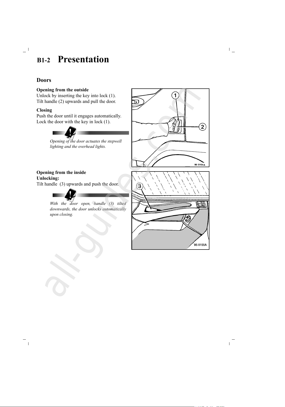
Opening from the outside
Unlock by inserting the key into lock (1).
Tilt handle (2) upwards and pull the door.
Closing
Push the door until it engages automatically.
Lock the door with the key in lock (1).
Opening of the door actuates the stepwell
lighting and the overhead lights.
Opening from the inside
Unlocking:
Tilt handle (3) upwards and push the door.
With the door open, handle (3) tilted
downwards, the door unlocks automatically
upon closing.
All manuals and user guides at all-guides.com
all-guides.com
Page 17
B1-3 Presentation
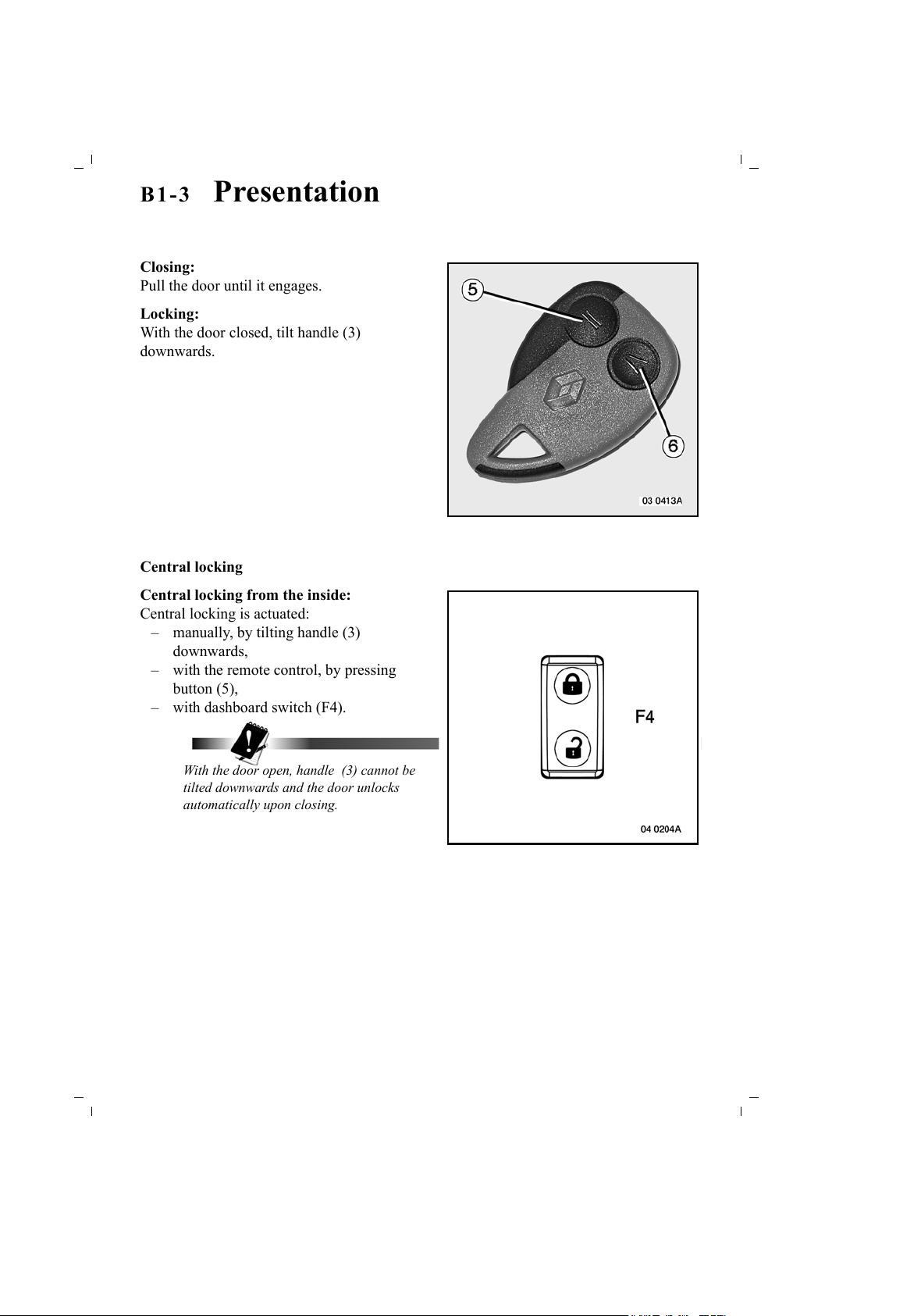
Closing:
Pull the door until it engages.
Locking:
With the door closed, tilt handle (3)
downwards.
Central locking
Central locking from the inside:
Central locking is actuated:
– manually, by tilting handle (3)
downwards,
– with the remote control, by pressing
button (5),
– with dashboard switch (F4).
With the door open, handle (3) cannot be
tilted downwards and the door unlocks
automatically upon closing.
All manuals and user guides at all-guides.com
Page 18
B1-4 Presentation
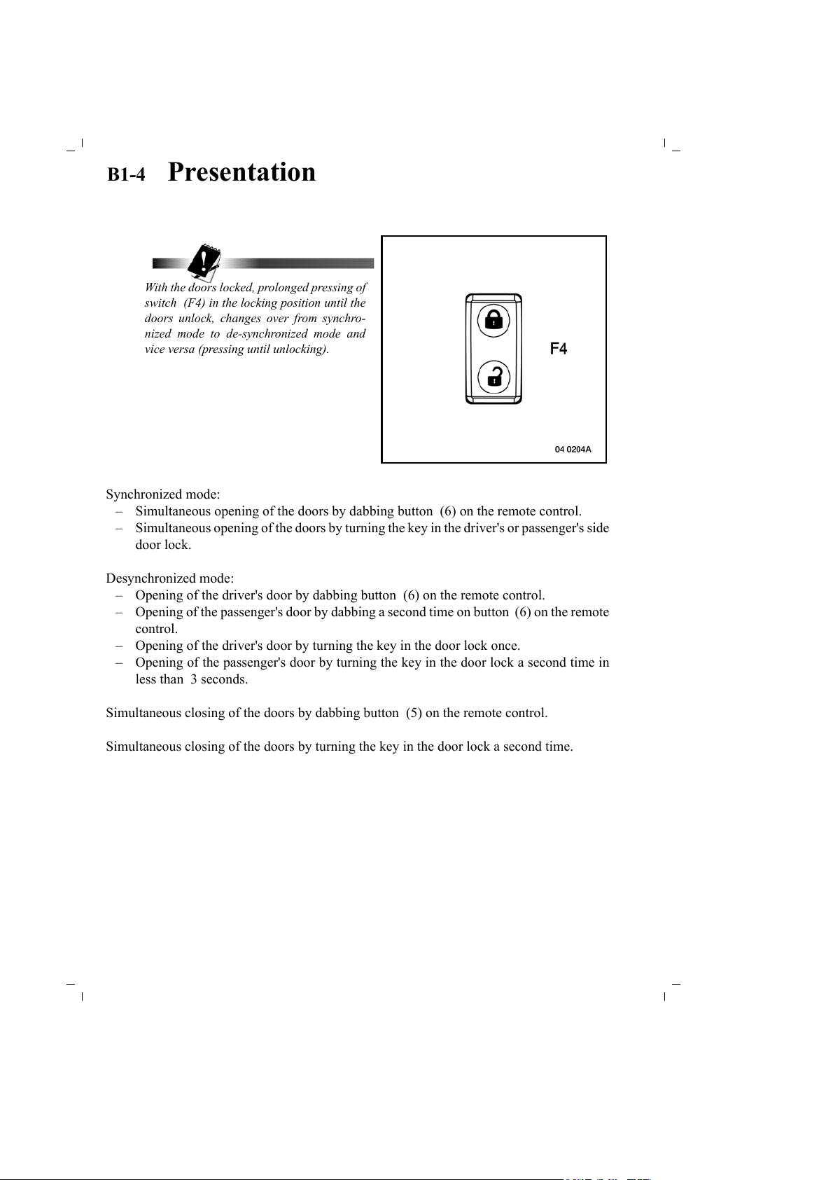
With the doors locked, prolonged pressing of
switch (F4) in the locking position until the
doors unlock, changes over from synchro-
nized mode to de-synchronized mode and
vice versa (pressing until unlocking).
Synchronized mode:
– Simultaneous opening of the doors by dabbing button (6) on the remote control.
– Simultaneous opening of the doors by turning the key in the driver's or passenger's side
door lock.
Desynchronized mode:
– Opening of the driver's door by dabbing button (6) on the remote control.
– Opening of the passenger's door by dabbing a second time on button (6) on the remote
control.
– Opening of the driver's door by turning the key in the door lock once.
– Opening of the passenger's door by turning the key in the door lock a second time in
less than 3 seconds.
Simultaneous closing of the doors by dabbing button (5) on the remote control.
Simultaneous closing of the doors by turning the key in the door lock a second time.
All manuals and user guides at all-guides.com
Page 19
B1-5 Presentation
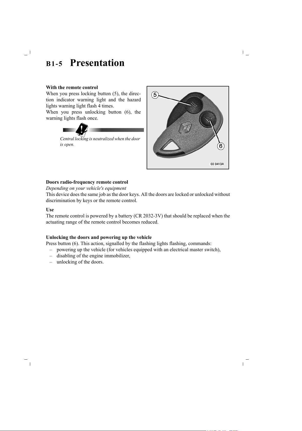
With the remote control
When you press locking button (5), the direc-
tion indicator warning light and the hazard
lights warning light flash 4 times.
When you press unlocking button (6), the
warning lights flash once.
Central locking is neutralized when the door
is open.
Doors radio-frequency remote control
Depending on your vehicle's equipment
This device does the same job as the door keys. All the doors are locked or unlocked without
discrimination by keys or the remote control.
Use
The remote control is powered by a battery (CR 2032-3V) that should be replaced when the
actuating range of the remote control becomes reduced.
Unlocking the doors and powering up the vehicle
Press button (6). This action, signalled by the flashing lights flashing, commands:
– powering up the vehicle (for vehicles equipped with an electrical master switch),
– disabling of the engine immobilizer,
– unlocking of the doors.
All manuals and user guides at all-guides.com
Page 20
B1-6 Presentation
Locking of the doors only
Press button (5). This action, signalled by the flashing lights flashing 4 times, commands
locking of the doors. The vehicle remains powered up with the engine immobilizer disabled.
Powering down the vehicle
A 2
nd
press on button (5) less than 10 minutes after the 1st press, signalled by a long flash
lasting 1.5 seconds, causes:
– activation of the engine immobilizer,
– opening of the master switch for vehicles equipped with an electrical master switch.
If the flashing lights flash more than 4 times (e.g. after replacing the remote control battery),
during the flashing phase, press one of the buttons 2 times to reactivate the remote control.
If the flashing lights do not flash during the locking phase (in spite of the fact that they are
working normally), it means that:
– at least one of the doors is not closed properly,
– there is a door locking actuator fault,
– there is a receiver fault.
All manuals and user guides at all-guides.com
Page 21
B1-7 Presentation
Interior and stepwell lighting
The vehicle is provided with 2 overhead lights, one above each of the doors, and 2 stepwell
lights.
These lights come on and go out when the doors are opened and closed, when the vehicle is
unlocked and locked and when the ignition key is in the "on" position prior to starting.
– When the doors are unlocked by the remote control, the interior lights comes on for a
period of 17 seconds.
– When a door is opened, the interior lights stay on or come on again if they have gone
out, for a period of 5 minutes (if at least one door remains open beyond that limit).
– After a door is closed, the interior lights stay on for 17 seconds, to give you time to put
the key into the ignition switch.
– Switching on the ignition immediately causes the interior lights to go out.
– Stopping the engine causes the interior lights to come on for a period of 17 seconds.
– Locking of the doors causes the interior lights to immediately go out.
The overhead lights can be forced to come on by actuating one of the two switches.
See page(s) B2-74.
All manuals and user guides at all-guides.com
all-guides.com
Page 22
B1-8 Presentation
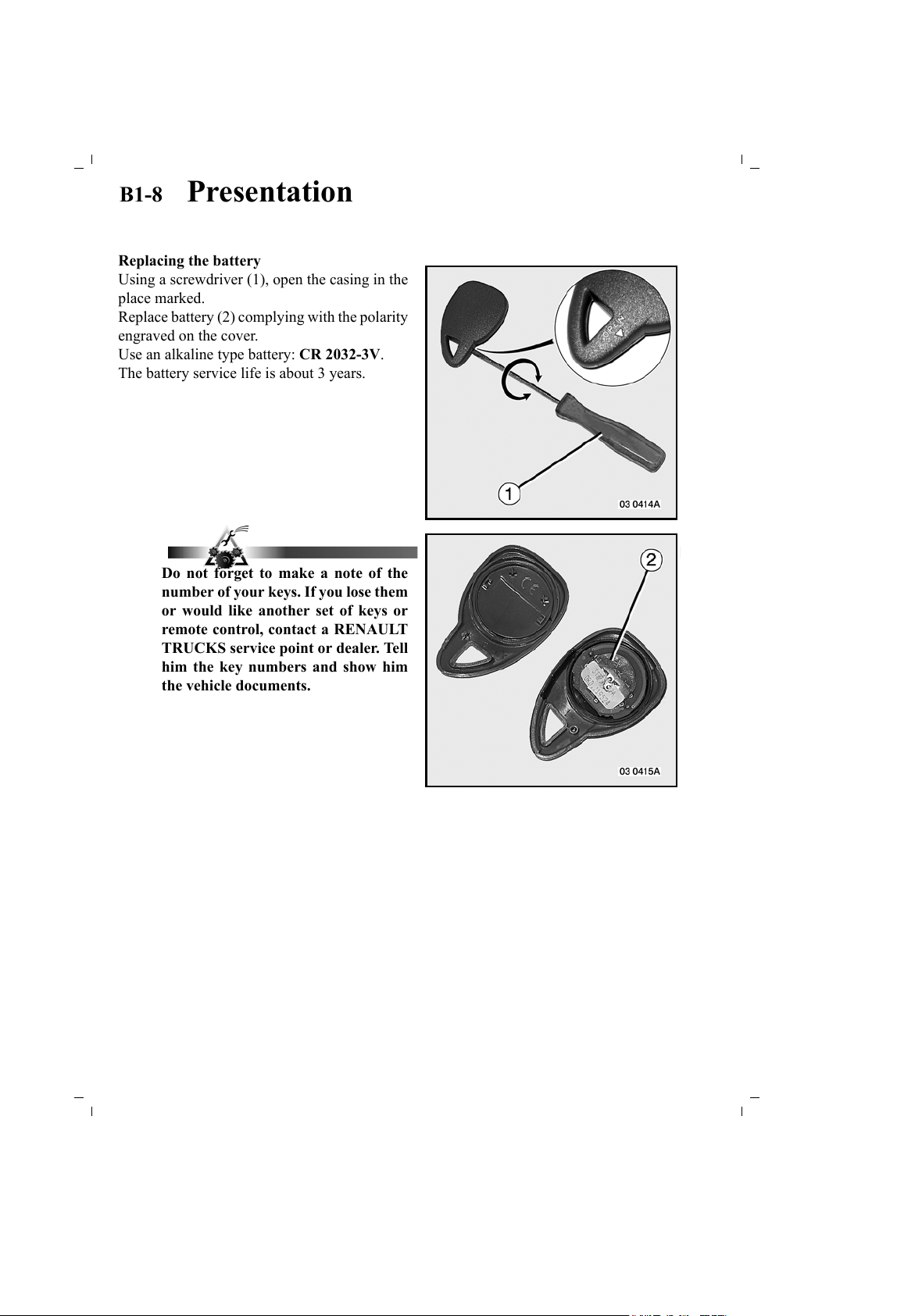
Replacing the battery
Using a screwdriver (1), open the casing in the
place marked.
Replace battery (2) complying with the polarity
engraved on the cover.
Use an alkaline type battery: CR 2032-3V.
The battery service life is about 3 years.
Do not forget to make a note of the
number of your keys. If you lose them
or would like another set of keys or
remote control, contact a RENAULT
TRUCKS service point or dealer. Tell
him the key numbers and show him
the vehicle documents.
All manuals and user guides at all-guides.com
Page 23
B1-9 Presentation
Alarm
Features
– "Panic" button in the event of aggression to the driver.
– Volumetric protection of the cab.
– Perimetric protection of cab doors.
– Cab tilting protection.
– "After ignition positive" protection.
– Protection against disconnection of batteries and disconnection of siren (self-powered
siren).
– Alarm activation warning light on the control box.
– A pictogram and a message on the information display and a sound given off by the
siren serve to identify the nature of the aggression.
The following features are only possible if the vehicle body and/or the coupled trailer is
equipped with the freight protection box distributed by the RENAULT TRUCKS Boutique.
– Perimetric protection of vehicle body and/or trailer doors.
– Surveillance of onboard freight while at a standstill or when moving (opening of doors
and unplugging of trailer electrical socket).
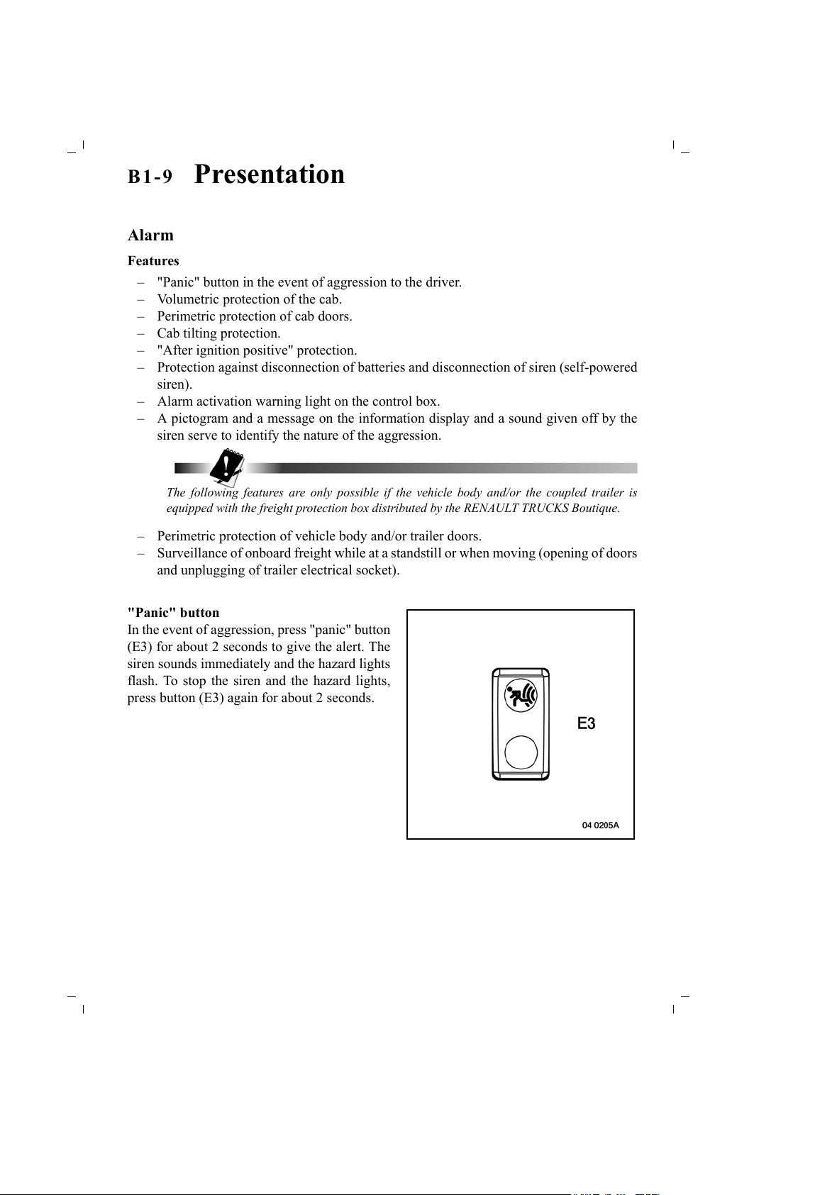
"Panic" button
In the event of aggression, press "panic" button
(E3) for about 2 seconds to give the alert. The
siren sounds immediately and the hazard lights
flash. To stop the siren and the hazard lights,
press button (E3) again for about 2 seconds.
All manuals and user guides at all-guides.com
Page 24
B1-10 Presentation
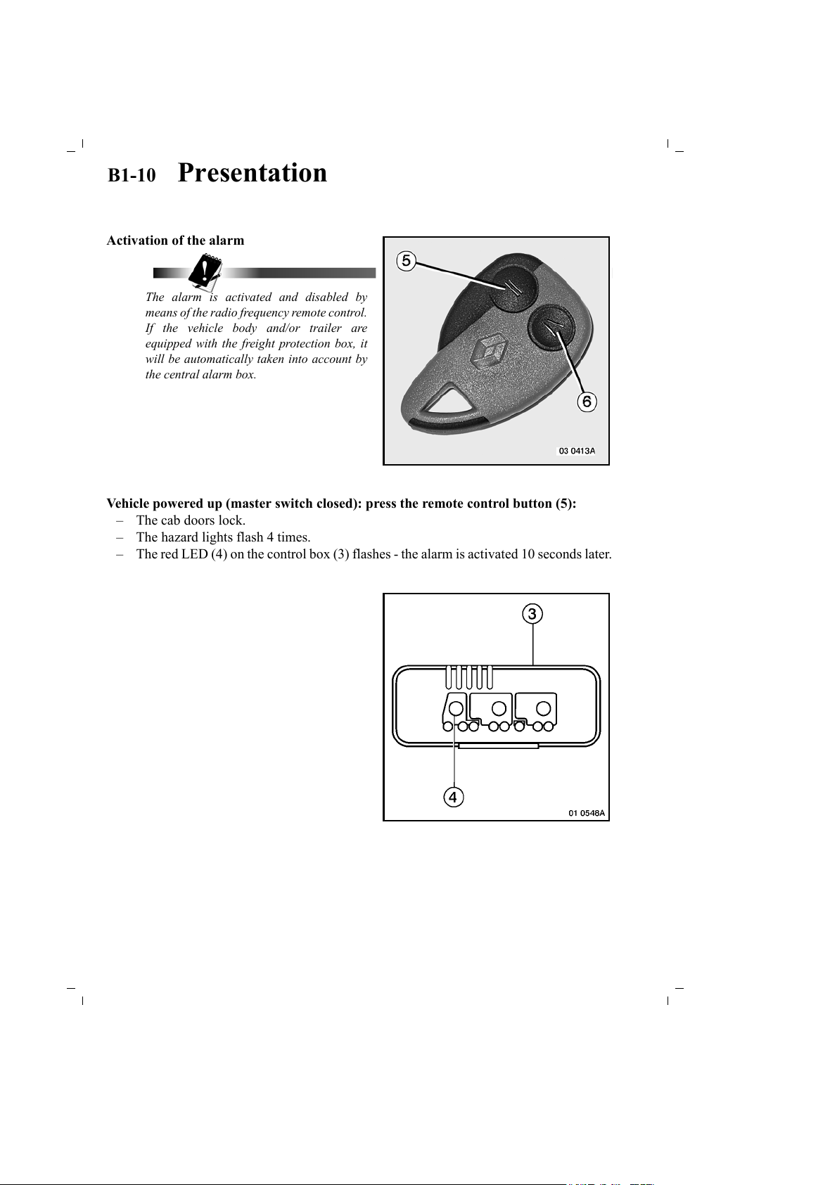
Activation of the alarm
The alarm is activated and disabled by
means of the radio frequency remote control.
If the vehicle body and/or trailer are
equipped with the freight protection box, it
will be automatically taken into account by
the central alarm box.
Vehicle powered up (master switch closed): press the remote control button (5):
– The cab doors lock.
– The hazard lights flash 4 times.
– The red LED (4) on the control box (3) flashes - the alarm is activated 10 seconds later.
All manuals and user guides at all-guides.com
Page 25
B1 -11 Presentation
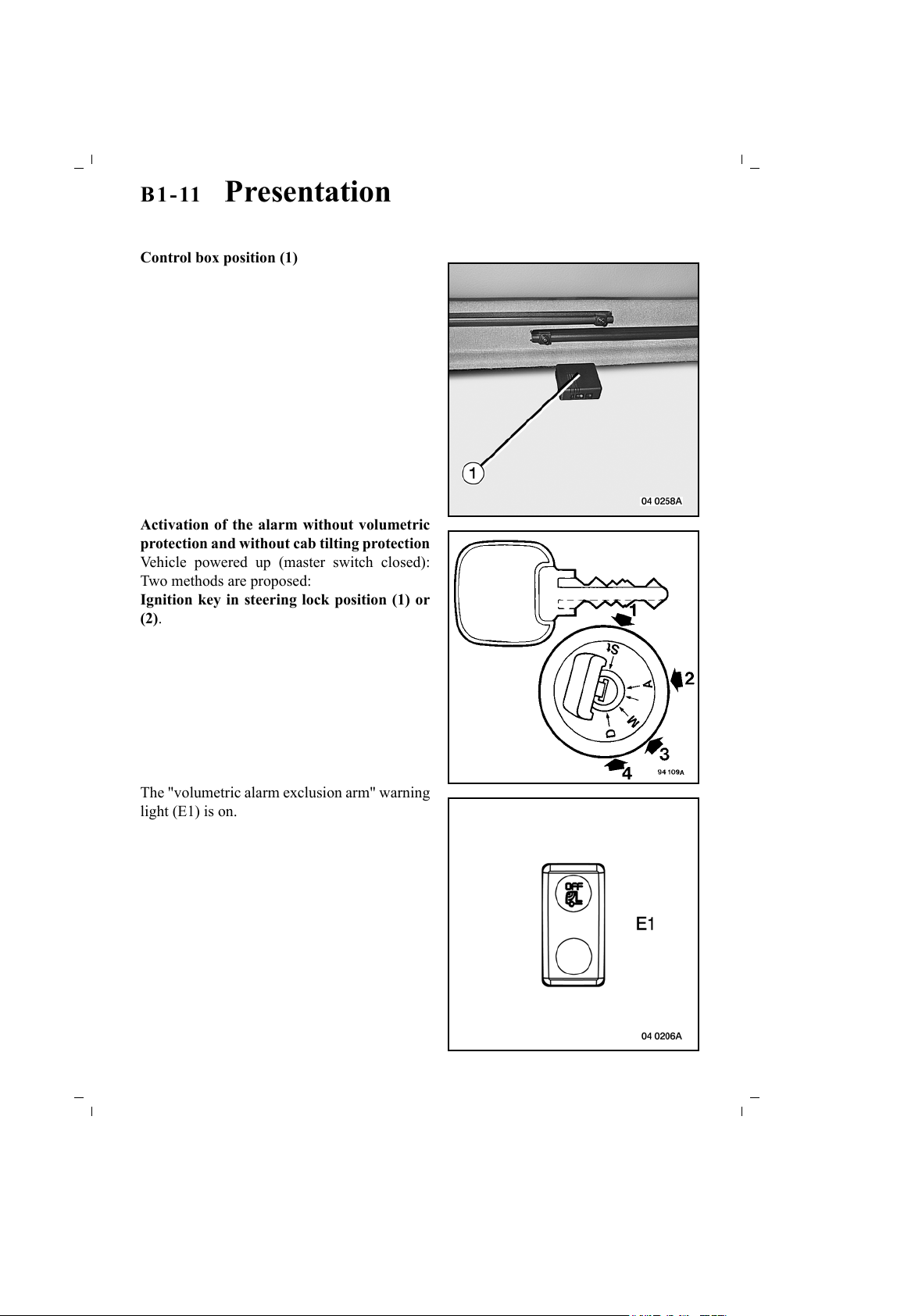
Control box position (1)
Activation of the alarm without volumetric
protection and without cab tilting protection
Vehicle powered up (master switch closed):
Two methods are proposed:
Ignition key in steering lock position (1) or
(2).
The "volumetric alarm exclusion arm" warning
light (E1) is on.
All manuals and user guides at all-guides.com
Page 26
B1-12 Presentation
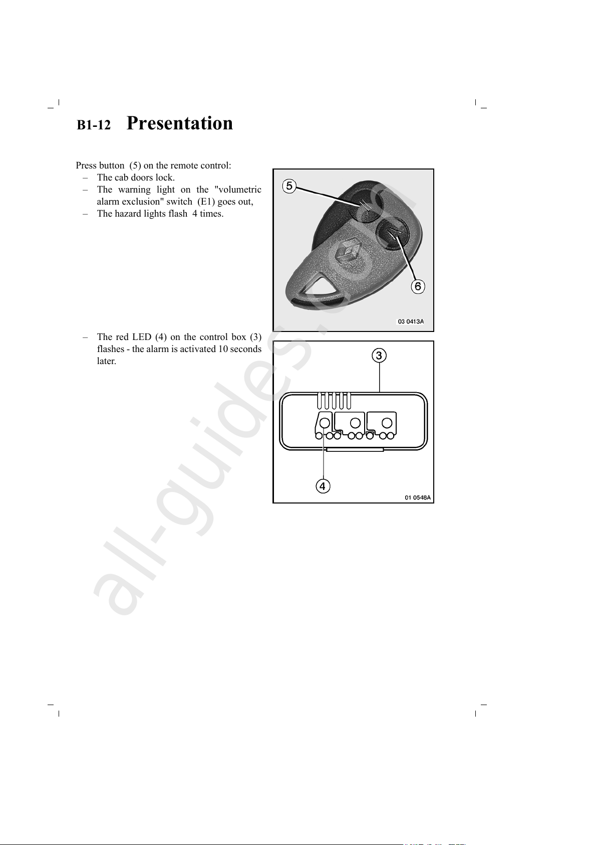
Press button (5) on the remote control:
– The cab doors lock.
– The warning light on the "volumetric
alarm exclusion" switch (E1) goes out,
– The hazard lights flash 4 times.
– The red LED (4) on the control box (3)
flashes - the alarm is activated 10 seconds
later.
All manuals and user guides at all-guides.com
all-guides.com
Page 27
B1 -13 Presentation
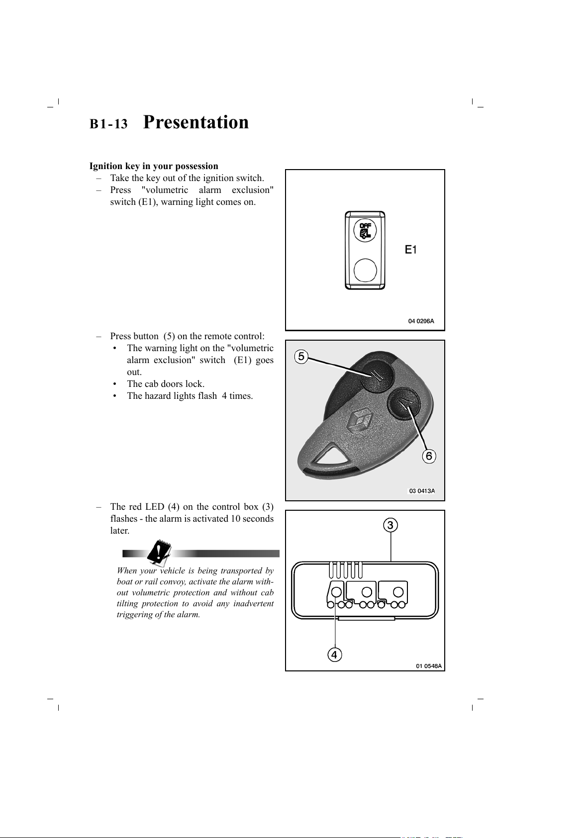
Ignition key in your possession
– Take the key out of the ignition switch.
– Press "volumetric alarm exclusion"
switch (E1), warning light comes on.
– Press button (5) on the remote control:
• The warning light on the "volumetric
alarm exclusion" switch (E1) goes
out.
• The cab doors lock.
• The hazard lights flash 4 times.
– The red LED (4) on the control box (3)
flashes - the alarm is activated 10 seconds
later.
When your vehicle is being transported by
boat or rail convoy, activate the alarm with-
out volumetric protection and without cab
tilting protection to avoid any inadvertent
triggering of the alarm.
All manuals and user guides at all-guides.com
Page 28
B1-14 Presentation
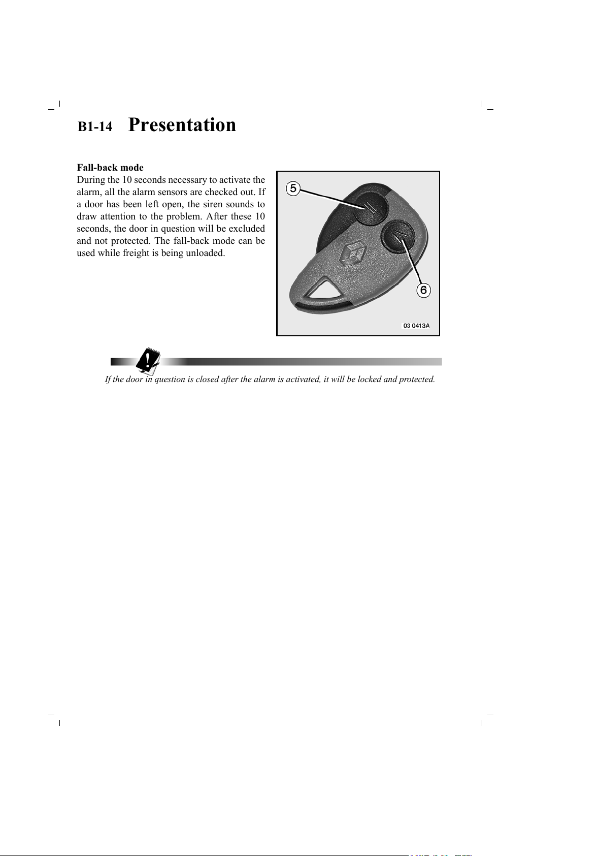
Fall-back mode
During the 10 seconds necessary to activate the
alarm, all the alarm sensors are checked out. If
a door has been left open, the siren sounds to
draw attention to the problem. After these 10
seconds, the door in question will be excluded
and not protected. The fall-back mode can be
used while freight is being unloaded.
If the door in question is closed after the alarm is activated, it will be locked and protected.
All manuals and user guides at all-guides.com
Page 29
B1 -15 Presentation
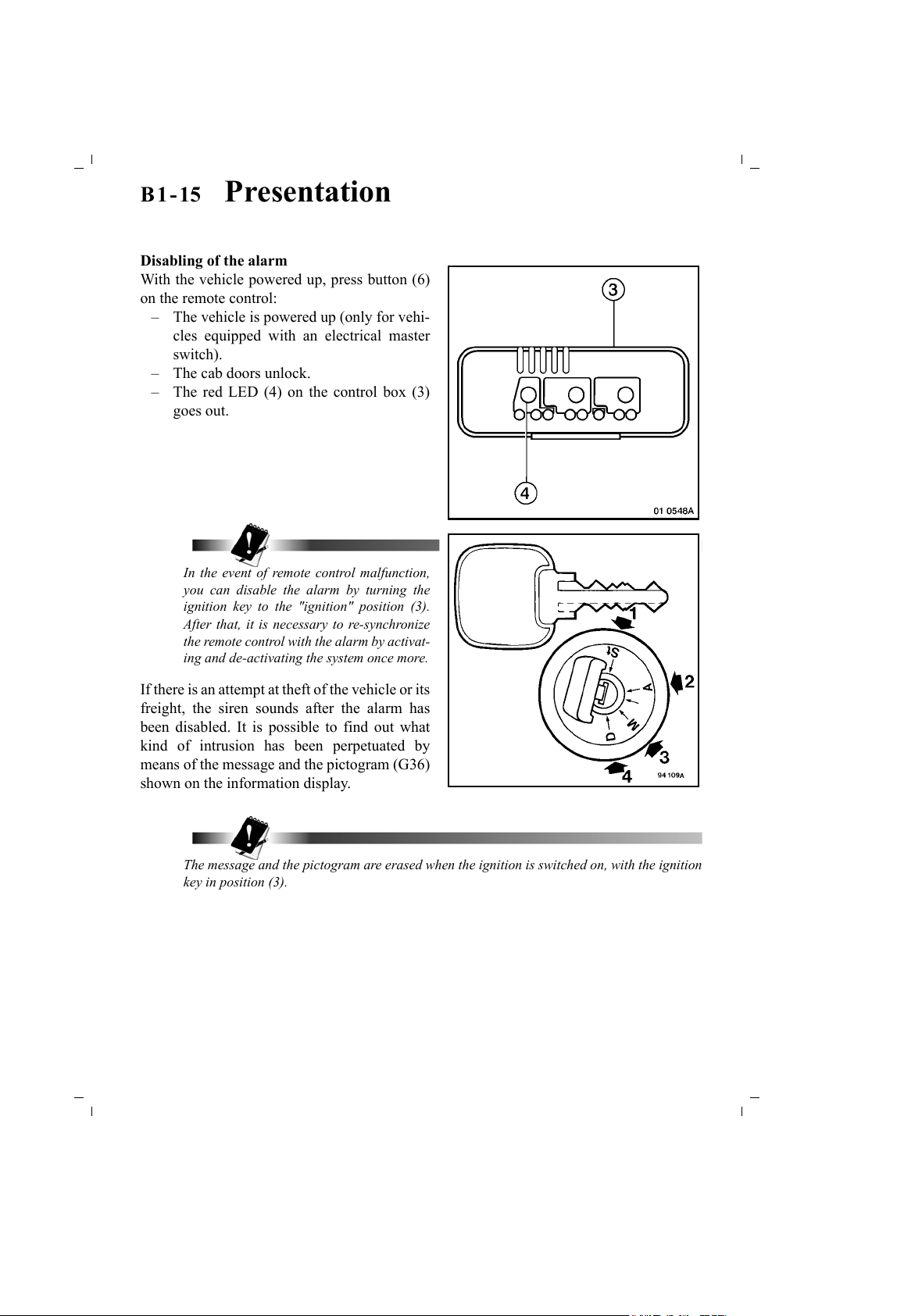
Disabling of the alarm
With the vehicle powered up, press button (6)
on the remote control:
– The vehicle is powered up (only for vehi-
cles equipped with an electrical master
switch).
– The cab doors unlock.
– The red LED (4) on the control box (3)
goes out.
In the event of remote control malfunction,
you can disable the alarm by turning the
ignition key to the "ignition" position (3).
After that, it is necessary to re-synchronize
the remote control with the alarm by activat-
ing and de-activating the system once more.
If there is an attempt at theft of the vehicle or its
freight, the siren sounds after the alarm has
been disabled. It is possible to find out what
kind of intrusion has been perpetuated by
means of the message and the pictogram (G36)
shown on the information display.
The message and the pictogram are erased when the ignition is switched on, with the ignition
key in position (3).
All manuals and user guides at all-guides.com
Page 30

B1-16 Presentation
"Starting impossible"
In the event of transponder malfunction, it is impossible to start the engine.
The message "Starting impossible" is shown on the information display.
Call upon the nearest RENAULT TRUCKS service point or dealer.
Stopping of the alarm without opening the door(s)
If the doors are unlocked and the alarm stops without the doors being opened within a period
of 2 minutes, the doors are locked and the alarm is re-activated automatically.
All manuals and user guides at all-guides.com
Page 31

B1 -17 Presentation
Front grille
Pull the bottom part of the radiator grille to
open it. Push it to close.
WHEN WORKING AT THE FRONT END OF THE VEHICLE WITH THE FRONT GRILLE
OPEN, ENSURE THAT THE WINDSCREEN WIPER SWITCH IS IN THE "OFF" POSITION.
IT MIGHT PROVE TO BE DANGEROUS IF YOU PLACE YOUR HANDS ON THE SCREEN
WIPER LINKAGE. IF POSSIBLE, DISENGAGE THE MASTER SWITCH.
All manuals and user guides at all-guides.com
all-guides.com
Page 32

B1-18 Presentation
Side fairings
Opening
Unlock side fairings (1):
Lift up catches (2), pivot them through 1/4 of a
turn, then pull the fairings until they are held by
straps (3).
All manuals and user guides at all-guides.com
Page 33

B1 -19 Presentation
It is possible to remove the fairings completely
by unhooking the holding straps (3) and pulling
the fairings towards yourself to dislodge them
from the rubber sandwich mountings (4).
Closing
If the fairings have been removed , fit them into
the rubber sandwich mountings (4) by pushing
them at the bottom and fasten the strap snap
hooks (3).
Push the side fairings (1), pivot the catches (2)
through 1/4 of a turn.
Ensure that the fairings are correctly locked.
All manuals and user guides at all-guides.com
Page 34

B1-20 Presentation
Cab tilting
NEVER TILT THE CAB WHILE THE ENGINE IS RUNNING.
Before restarting the engine, check:
– Cab raised: that the gear lever is in
neutral.
– Cab lowered: that the gearshift linkage is
locked, after checking that all gears shift
correctly.
When working underneath the cab (on the
engine, etc...), the cab must be fully tilted.
Any work on the cab tilt hydraulic system
requires strict observance of the safety instruc-
tions and should therefore be carried out by a
RENAULT TRUCKS service point or dealer.
Cab tilting hydraulic system
Filling and checking oil level
With the cab in the "road" position, fill with oil
through oil reservoir filler port (2).
To gain access to the oil reservoir,, slacken
screw (1) and pivot the headlamp insert.
Check the oil level: the oil should be flush with
the top of piston (3) when it is in the "down"
position.
Carefully carry out one complete tilting ma-
noeuvre (up and down), then check the oil level
again. In the event of malfunction, consult a
RENAULT TRUCKS service point or dealer.
All manuals and user guides at all-guides.com
Page 35

B1 -21 Presentation
Depending on your vehicle's equipment
Before tilting the cab:
– Lock the storage compartments.
– Empty the bottle-holder.
– Stop the refrigerator.
Depending on your vehicle's equipment
Mechanical control
With the vehicle stationary, engine shut down,
gear lever in neutral, doors properly closed,
make sure that no loose articles in the cab can
be thrown against the windscreen. Clear the
area in front of the cab. Place lever (1) in the
"up" position. Use operating bar (2).
Since unlocking is automatic, pump until the
cab tilts fully. Use jack handle (3) to add lever-
age to the operating bar (2). Force the operat-
ing bar fully downwards.
To return the cab to the "road" position, place
lever (1) n the "down" position, pump until the
cab locks automatically.
If you experience difficulty in tilting, return
the cab to the "road" position and check the
oil level. Top up with oil, if necessary.
Carefully carry out one complete tilting ma-
noeuvre (up and down), then check the oil
level again. In the event of malfunction, con-
sult a RENAULT TRUCKS service point or
dealer.
It is impossible to open the front grille when
the cab is tilted.
All manuals and user guides at all-guides.com
Page 36

B1-22 Presentation
Depending on your vehicle's equipment
Electrical control
Depending on the assembly, the mechanical
control is assisted by an electrical control.
Place lever (1) in the "up" position. Use operat-
ing bar (2).
With the ignition switched on, press button (4).
Since unlocking is automatic, pump until the
cab tilts fully.
To return the cab to the "road" position, place
lever (1) in the "down" position, press button
(4) until the cab locks automatically. Do not
leave your hands on the step during the ma-
noeuvre.
After 2 successive tilting manoeuvres (up and down), wait for 15 minutes for the pump motor
to cool down before starting again.
If you experience difficulty in tilting, return the cab to the "road" position and check the oil
level.
In the event of electrical failure (control or pump), use the mechanical cab tilt control.
All manuals and user guides at all-guides.com
all-guides.com
Page 37

B1 -23 Presentation
External storage locker(s)
Depending on your vehicle's equipment
Opening and closing of compartment (1) with
handle (2). Locking with key lock.
Opening and closing of compartment (1) with
handle (2). Locking with key lock.
All manuals and user guides at all-guides.com
Page 38

B1-24 Presentation
Opening: Pull control (1) to unlock the door. Lift up door (2). There is a strut to hold
the door open.
A light fitted with a switch comes on when the master switch is engaged.
Closing: Push control: (1) free the strut and close door (2). Locking is automatic.
The tool locker under the cab is not provided with a strut. It is held open by a hard spot that
has to be overcome when closing.
All manuals and user guides at all-guides.com
Page 39

B1 -25 Presentation
Fuel tank(s)
Fuel filler cap
The filler cap is locked by a key lock (1).
Vehicle equipped with two fuel tanks
without changeover valve
Since there is no fuel gauge switch, the fuel level gauge shows the total contents of both fuel
tanks.
When filling up with fuel, you are recommended to put fuel into both tanks.
Depending on your vehicle's equipment
SWITCH OFF THE INDEPENDENT HEATER BEFORE YOU FILL THE FUEL TANK(S).
All manuals and user guides at all-guides.com
Page 40

B1-26 Presentation
Master switch
Depending on your vehicle's equipment
Turn handle (1) through one quarter of a turn
to isolate the electrical installation except for
alarm, central door locking, tachograph, inde-
pendent heating timer and hazard lights.
If the vehicle is equipped with a remote control for electrically locking the doors coupled with
the master switch control, refer to page B-1-5 on how to use it.
All manuals and user guides at all-guides.com
Page 41

B1 -27 Presentation
"ADR" master switch (transport of dangerous materials)
Use of the ADR battery isolating switch
Several parameters are involved:
– ignition key inserted in ignition switch,
– chassis exterior switch,
– cab interior switch,
– following electrical consumers:
• side/parking lights,
• hazard lights,
• suspension,
• independent heating.
Operation
Cab interior switch (B4)
Chassis exterior switch (2)
Switch type operation
The battery isolating switch can be operated by
means of switch (B4) or (2).
If either of the two switches is actuated, it is es-
sential for the key to be put back into the igni-
tion switch and for the those switches to be in
the "ON" position to close the battery isolating
switch.
The "ADR" battery isolating switch serves to
supply electrical power to the vehicle if neither
of the two switches is actuated by the driver.
If either of the two switches is actuated, the
"ADR" battery isolating switch cuts the electri-
cal power supply to the vehicle and the engine
stops automatically.
All manuals and user guides at all-guides.com
all-guides.com
Page 42

B1-28 Presentation
Operation by insertion of ignition key in ignition switch
With the "ADR" battery isolating switch in the position for supplying electrical power to the
vehicle (switches (B4) - (1) not actuated and ignition key inserted in ignition switch): if the
driver takes the ignition key out of the ignition switch and if none of the electrical consumers
quoted earlier is in operation, the "ADR" battery isolating switch cuts the electrical power
supply to the vehicle after a period of 20 minutes.
The electrical power supply will be restored to the vehicle when the ignition key is inserted
into the ignition switch. If the driver’s door is locked by the door key, unlock it with that key.
Vehicle equipped with independent heating
(See page B2-66).
All manuals and user guides at all-guides.com
Page 43

B2-1 Presentation
RESENTATION
Driving position
Seats
For your own safety, it is essential to remove the plastic protective cover when
putting the vehicle into commission.
Seat suspension
Adjust the flexibility of the suspension according to the state of the road and the user's
weight.
Air-operated seats
Controls will only work if there is sufficient air pressure.
Driver's seat
Passenger(s) seat
Depending on your vehicle's equipment
Depending on seat use (i.e. driver, passenger, left or right hand drive), controls are located to
one side or the other. The seat type shown is just one possible solution.
1 - "Vertical" Ssuspension "vertical" flexibility adjustment:
– Upwards: hard suspension.
– Downwards: supple suspension.
2 - Fast suspension lowering.
3 - "Lower" lumbar support adjustment control.
4 - "Upper" lumbar support adjustment control.
5 - Side support adjustment.
6 - Heated seat cushion and squab (automatic thermostat-regulated operation).
FOR SAFETY REASONS, ALL SEAT ADJUSTMENT OPERATIONS MUST BE CARRIED
OUT WHEN THE VEHICLE IS AT A STANDSTILL.
WHEN THE VEHICLE IS MOVING, ANY USE OF THE SEATS IN A POSITION OTHER
THAN THAT OF "FACING THE ROAD" INVOLVES THE RESPONSIBILITY OF THE
USERS.
All manuals and user guides at all-guides.com
Page 44

B2-2 Presentation
All manuals and user guides at all-guides.com
Page 45

B2-3 Presentation
All manuals and user guides at all-guides.com
Page 46

B2-4 Presentation
All manuals and user guides at all-guides.com
all-guides.com
Page 47

B2-5 Presentation
All manuals and user guides at all-guides.com
Page 48

B2-6 Presentation
Dashboard
All manuals and user guides at all-guides.com
Page 49

B2-7 Presentation
All manuals and user guides at all-guides.com
Page 50

B2-8 Presentation
Depending on your vehicle's equipment
1 - Switches (see page B2-24)
2 - Air vent(s) control
3 - Air vent
4 - Information display
5 - Thermal comfort panel
6 - Ledge with non-slip surface (to be used only when the vehicle is stationary).
7- Fuses
8 - Storage spaces
9 - Electrical socket 24V (360W maxi)
10 - Storage drawer / modular space
11 - Electrical socket 12V (120W maxi)
12 - Modular space (radio)
13 - Cigar lighter
14 - Steering wheel adjuster
15 - Diagnostic socket
15 - Infomax socket
16 - Switches / modular space
17 - Modular space (tachograph)
18 - Parking brake control
19 - Air blower outlet
20 - Static trailer brake
21 - Trailer brake
All manuals and user guides at all-guides.com
Page 51

B2-9 Presentation
All manuals and user guides at all-guides.com
all-guides.com
Page 52

B2-10 Presentation
Instrument panel
A - Fuel minimum reserve warning light
B - Fuel level gauge
C - Engine cooling system temperature gauge
D - Air pressure gauge
E* - Tractor/rigid left-hand direction indicators warning light
F** - Trailer left-hand direction indicators warning light
G
- "INFORMATION" tell-tale light indicating that a new message has appeared
on the multi-function information display (see page B2-28)
H - Immediate stop "DANGER" warning light
I
- "SERVICE" warning light: Make your way to the nearest
RENAULT TRUCKS service point or dealer
J** - Trailer right-hand direction indicators warning light
K* - Tractor/rigid right-hand direction indicators warning light
L - Multi-function information display (see page B2-28)
All manuals and user guides at all-guides.com
Page 53

B2 -11 Presentation
M - Long range driving lights warning light
N- Not used
O - Independent heating in service warning light (see page B2-61)
P - Lift-up axle warning light
Q - Retarder(s) in service warning light
R - "SEAT BELT NOT BUCKLED" warning light
S - Parking brake warning light
T - Engine speed operating zone (see page C4-2)
U - Speedometer
V - Rev counter
W - Hazard lights warning light
X - Preheating warning light
Y - Windscreen defrosting warning light
Z- Not used
AA - Rear fog lights warning light
AB - Fog driving lights warning light
AC - Dipped beam headlights warning light
AD
- Comfort information display:
–Clock
– Outside temperature gauge
– Onboard radio
AE - Main beam headlights warning light
All manuals and user guides at all-guides.com
Page 54

B2-12 Presentation
Operation of direction indicator lights warning lights
Without trailer
As soon as a direction indicator or hazard lights control is activated, warning light (E) or (K)
should flash and the clicker should sound. If they are inoperative, one of the tractor bulbs is
defective.
** With trailer
As soon as a direction indicator or hazard lights control is activated, warning lights (E - F)
or (K - J) should flash and the clicker should sound.
If warning light (E) or (K) should flash and the clicker should sound. If they are inoperative,
one of the tractor bulbs is defective.
If warning light (F) or (J) is inoperative, one of the trailer bulbs is defective.
If the clicker is inoperative, there is a fault both on the tractor and on the trailer.
All manuals and user guides at all-guides.com
Page 55

B2 -13 Presentation
Tachograph
To avoid damage to the tachograph, carefully read the manufacturer’s
instruction book supplied with your vehicle’s onboard documents.
If warning pictogram (G61) is displayed, make sure that:
Analogue tachograph
– the tachograph chart is in place in the tachograph unit.
Digital tachograph
– the driver's tachograph chart (1) is in place in the tachograph tray.
If this is not the case, make your way to the nearest RENAULT TRUCKS service point or
dealer as quickly as possible to get the repair carried out.
Digital tachograph
To insert and eject the tachograph chart (1)
into and from the tachograph chart tray, the
vehicle must be at a standstill and the igni-
tion switched on. Upon opening of the tray,
the driving time and rest time information
shown on the multi-function display is auto-
matically zeroed.
Upon insertion of the driver's tachograph
chart, the driving help information previous-
ly recorded on the chart is shown on the
multi-function display after a few minutes.
While the data is being loaded from the driver's chart to the tachograph, it is possible to select
an activity and move away.
All manuals and user guides at all-guides.com
Page 56

B2-14 Presentation
Insertion of the paper roll
This operation must be carried out with the
vehicle at a standstill and the ignition
switched on.
Press key (1) to open the printer tray.
DEPENDING ON THE AMOUNT OF CHARTS PRINTED, THE HEAD OF THE THERMAL
PRINTER MAY BE VERY HOT AND THERE IS A RISK OF BURNING YOUR FINGERS.
Take the old paper roll out of the printer tray.
Insert the new paper roll into the printer tray
(see illustration).
See that the end of the paper roll (2) overlaps
the edge of the tray.
Press the front middle of the printer tray to
close.
The printer feeds the paper through automati-
cally.
Only paper rolls bearing the following indications may be used:
– type approval sign "e1 84",
– official approval sign "e1 174".
All manuals and user guides at all-guides.com
all-guides.com
Page 57

B2 -15 Presentation
ENSURE THE PRINTER TRAY IS ALWAYS KEPT CLOSED TO AVOID RISKS OF CUTTING
YOURSELF ON THE SHARP CUT EDGE OF THE PAPER.
Analogue tachograph
To open the tachograph chart tray, the vehicle must be at a standstill and the ignition switched
on. Upon opening the tray, the driving time and rest time information shown on the multi-func-
tion display is automatically reset to zero.
The multi-function information display (L) in-
dicates the activity of driver (1) depending on
the tachograph selection made.
All manuals and user guides at all-guides.com
Page 58

B2-16 Presentation
Key to warning pictograms
Depending on your vehicle's equipment
A text indicating the procedure to be followed or an information message is displayed below
the warning pictogram.
These warning pictograms are shown in the multi-function information display.
G1 - Driver information warning pictogram
G2 - Information display fault warning pictogram
G3
- Batteries warning pictogram
- Batteries charging fault warning pictogram
G4 - Engine oil pressure "Alert" warning pictogram
G5 - Engine oil temperature "ALERT" warning pictogram
G6 - Engine oil level "ALERT" warning pictogram
G7 - Engine oil level "OK" warning pictogram
G8 - Engine oil level information loss warning pictogram
G9
- Vehicle electronic fault warning pictogram
- Bodybuilder box fault warning pictogram
G10 - CAN bus link fault warning pictogram
All manuals and user guides at all-guides.com
Page 59

B2 -17 Presentation
G11 - Unknown electronic box warning pictogram
G12
- Engine electronic fault warning pictogram
- Air preheating "ALERT" warning pictogram
G13
– Air minimum pressure "ALERT" warning pictogram
– EBS fault warning pictogram
G14
- Trailer "ABS/EBS" warning pictogram:
– small pictogram: check-out of device upon ignition switch-on
(no fault)
– large pictogram: device fault "Information"
G15
- Tractor "ABS/EBS" warning pictogram:
– small pictogram: check-out of device upon ignition switch-on
(no fault)
– large pictogram: device fault "Information"
G16 - Brake pads wear warning pictogram
G17 - Brakes high temperature warning pictogram
G18 - Air management fault warning pictogram
G19
- Parking brake not applied upon opening of driver's door warning
pictogram
G20 - Hill-start assist warning pictogram
G21 - Lighting fault warning pictogram
G22 - Water in fuel warning pictogram
G23 - Fuel pressure trouble warning pictogram
All manuals and user guides at all-guides.com
Page 60

B2-18 Presentation
G24 - Fuel bleeding in progress warning pictogram
G25
- Driver’s presence warning pictogram: brake or accelerator pedal
depressed
G26 - Clutch overheating warning pictogram
G27 - Fleet management fault warning pictogram
G28 - Maintenance alert warning pictogram
G29 - Electronic air suspension "ALERT" warning pictogram
G30 - Engine cooling system temperature "ALERT" warning pictogram
G31 - Engine coolant low level warning pictogram
G32 - Air filter and/or fuel filter clogging warning pictogram
G33 - Gearbox fault warning pictogram
G34 - Piloted starter trouble warning pictogram
G35 - Electronic engine immobilizer fault warning pictogram
G36 - Alarm warning pictogram
All manuals and user guides at all-guides.com
Page 61

B2 -19 Presentation
G37 - Engine overspeed warning pictogram
G38 - Retarder fault warning pictogram
G39 - Cruise control in service warning pictogram
G40 - Not used
G41
- Gearbox PTOs in service warning pictogram
Item numbers (1-2-3) are displayed according to the PTOs engaged.
G42 - PTO maximum speed warning pictogram
G43 - PTO minimum speed warning pictogram
G44 - Inter-wheel diff. lock in service warning pictogram
G44 - Inter-wheel diff. lock in service warning pictogram
G45
- Wheel slip or "ASR" in service warning pictogram
- "ASR" threshold change warning pictogram
G46 - "ASR" disconnected warning pictogram (roller bench testing)
G47 - Electronic air suspension "INFORMATION" warning pictogram
G48 - Axle load-shedding "INFORMATION" warning pictogram
All manuals and user guides at all-guides.com
all-guides.com
Page 62

B2-20 Presentation
G49 - Revolving beacons in service warning pictogram
G50 - Working spotlight warning pictogram
G51 - Cab tilting trouble warning pictogram
G52 - Screen wash reservoir level warning pictogram
G53 - Message received warning pictogram (fleet management)
G74 - Information pictogram: vehicle equipped with an ESP system
G75 - ESP calibration mode warning pictogram
G76 - Anti-tipover device in service warning pictogram
G77 - ASR in service warning pictogram
All manuals and user guides at all-guides.com
Page 63

B2 -21 Presentation
Key to "gearbox" warning pictograms
Depending on your vehicle's equipment
G54 - OPTIDRIVER 2 warning pictogram: move lever to position (D)
G55 - OPTIDRIVER 2 warning pictogram: move lever to position (N)
G56 - OPTIDRIVER 2 warning pictogram: integral automatic mode
G57
- OPTIDRIVER 2 warning pictogram: full-time or part-time
manual mode
G58 - OPTIDRIVER 2 warning pictogram: maximum vehicle mobility
G59 - OPTIDRIVER 2 warning pictogram: use brakes or retarders
G60 - Gearbox splitter fault warning pictogram
All manuals and user guides at all-guides.com
Page 64

B2-22 Presentation
Key to "tachograph" warning pictograms
Depending on your vehicle's equipment
G61
- Tachograph fault warning pictogram
- Driving style information pictogram
G62 - Cumulated driving time indication pictogram
G63 - Cumulated rest time indication pictogram
G64 - Rest in progress indication pictogram
G65 - Availability time indication pictogram
G66 - Working time indication pictogram
All manuals and user guides at all-guides.com
Page 65

B2 -23 Presentation
Key to "bodybuilder equipment" information pictograms
Depending on your vehicle's equipment
G67 - Body interior lighting tell-tale pictogram
G68 - Bodybuilder system unlock tell-tale pictogram
G69 - Bodybuilder system active tell-tale pictogram
G70 - Tail-lift in dangerous position warning pictogram
G71 - Tipper in working position warning pictogram
G72 - Crane deployed warning pictogram
G73 - Sideboard open warning pictogram
All manuals and user guides at all-guides.com
Page 66

B2-24 Presentation
Key to switches
Dashboard
All manuals and user guides at all-guides.com
all-guides.com
Page 67

B2 -25 Presentation
Depending on your vehicle's equipment
A1 - "ASR" control switch
A2 - Hill-start assist control switch
A3 - Hazard lights control (see page C-4-46)
A4 - Retarder control switch (manual / automatic)
A5 - Power take-off control switch
A6 - Fast idling ON/OFF control
A7 - Fast idling engine speed regulator ON/OFF control
B1 - Additional PTO control switch
B2 - Engine PTO control
B3 - Lift-up axle control switch
B4 - Master switch cut-off control switch (ADR)
B5 - Working spotlight control switch
B6 - Bodybuilder's equipment control switch
B7 - Bodybuilder's lighting control switch
C1 - Suspension "RAISE / LOWER" control
C2 - "MEMORIZE / RECALL MEMORIZED SETTING" control
C3 - "RETURN TO ROAD POSITION / STANDBY" control
C4 - Axle load-shedding control switch
C5 - Inter-wheel diff. lock control switch (4x2 - 6x2)
C6 - Bleed water from fuel control
C7 - Blanking plug
D1 - Headlights beam height adjustment control
All manuals and user guides at all-guides.com
Page 68

B2-26 Presentation
Ledge
E1 - Volumetric alarm exclusion control switch
E2 - Reversing buzzer control switch
E3 - "PANIC" alarm control switch
E4 - Revolving beacon switch
E5 - Extra lights control
E6 - Red interior lighting control
All manuals and user guides at all-guides.com
Page 69

B2 -27 Presentation
Engine tunnel console
F1 - Independent heating rheostat
F2 - Independent heating control switch
F3 - Sun-roof control switch
F4 - Central doors locking control switch
F5 - Trailer brake control switch
F6 - Air/water independent heating by-pass control
All manuals and user guides at all-guides.com
Page 70

B2-28 Presentation
Multi-function information display
Description:
The multi-function information display is di-
vided into 5 distinct zones.
Zone (1)
Zone displaying active function pictograms
and present faults.
When you activate a new function or if a fault
appears on the vehicle, the pictogram symbol-
izing the function or fault is first of all dis-
played in zone (2) for 15 seconds. Then, it is
displayed in zone (1).
Any action on control (AF) is displayed direct-
ly in zone (1).
The function pictograms are aligned starting on the left and the fault pictograms are aligned
starting on the right.
Zone (2)
This is the main information display zone. Here, the different menus are displayed.
When the ignition is switched on:
– If the engine is not started immediately, the oil level is displayed for a few seconds
(see page C-2-2).
– The pictograms connected with the auto-test are displayed for a few seconds (see page
C2-5).
– Once the previously mentioned controls have finished their action, the "supplementary
driving information" menu is displayed.
When you activate a new function or if a fault appears, the pictogram and the related text
are displayed for a moment in this zone, then the active menu before manipulation or
appearance of the fault is displayed again. The pictogram is then displayed in zone (1).
Any action on control (AF) is displayed in zone (1).
When zone (1) is full, the following pictograms are displayed in succession every 3 seconds in
zone (2).
All manuals and user guides at all-guides.com
Page 71

B2 -29 Presentation
Zone (3)
Total mileage (in km).
Zone (4)
When the ignition is switched on:
– information connected with the tachograph.
During driving:
– information connected with the "cruise control" function.
Zone (5)
information connected with the use of the gearbox.
The button (AF) has a different function de-
pending on whether you are in the "SUPPLE-
MENTARY DRIVING INFORMATION"
menu or in one of the other menus or
sub-menus.
Supplementary "driving information" menu
– Press control (AF) each time to go to the next screen (see page B-2-32).
– When a pictogram appears in display zone (2), press control (AF) to transfer the
pictogram to zone (1) without waiting for the end of the time-delay.
Other menus
Press control (AF) to go directly to the "SUPPLEMENTARY DRIVING INFORMATION"
menu (without confirmation).
All manuals and user guides at all-guides.com
all-guides.com
Page 72

B2-30 Presentation
Onboard radio / display remote control
The "RADIO/DISPLAY" remote control, lo-
cated under the steering wheel, serves to adjust
the radio without taking your hands off the
steering wheel. It also serves to "navigate" in
the different menus of the information display.
IN "DISPLAY" MODE, YOU ARE ADVISED TO USE THE REMOTE CONTROL WHEN THE
VEHICLE IS STATIONARY AND CORRECTLY PARKED, FOR SAFETY REASONS.
Functions
1– Select stations (radio).
2– Go back to menu or previous setting (display).
3– Increase radio sound volume / move around in menu.
4– Call up main menu / access menu or sub-menu selected / confirm settings (display).
5– Reduce radio sound volume / move around in menu.
6– Activate automatic station search (radio).
7– Scroll through memorized radio stations / scroll through menus.
All manuals and user guides at all-guides.com
Page 73

B2 -31 Presentation
All manuals and user guides at all-guides.com
Page 74

B2-32 Presentation
All manuals and user guides at all-guides.com
Page 75

B2 -33 Presentation
Supplementary driving information
Using control (AF) (see page B-2-30), ), it is possible to display different information items
in succession, that can amount to 6 in total and vary depending on your vehicle's equip-
ment.
The display of this information is time-delayed when the ignition is switched on, with the
engine running or shutdown, and when the vehicle is not moving.
As soon as the vehicle moves off, if you select an information item, it remains permanently
displayed.
1– Cumulated driving time.
Cumulated rest time.
The cumulated rest time is incremented after a period of 15 minutes of rest or avail-
ability at a stretch.
The cumulated driving time displayed on the instrument panel corresponds to the
effective vehicle running time (speed different from 0 km/h).
Brief stops, due to traffic, are automatically deducted.
This information is reset to zero:
• when the tachograph chart tray is closed,
• when driving or working is resumed after 45 minutes of accumulated rest.
The times displayed are given for guidance purposes. Only information recorded on the chart
has any legal value.
2– Partial mileage (in km).
Average road speed.
This information is reset to zero by pressing control (AF) and keeping it depressed for
more than 15 seconds.
3– Instant fuel consumption in litres per 100 km.
Average fuel consumption in litres per 100 km.
The instant fuel consumption is given for guidance purposes - it may reach substantial
proportions during acceleration or when moving off, but it is not significant of the
vehicle's average fuel consumption.
4– Total engine operating hourmeter.
Engine operating hourmeter with vehicle stationary.
5– Battery voltage.
Engine oil pressure.
6– Date.
Vehicle road speed in the unit you have not chosen for the instrument panel
speedometer (U) (mph or km/h).
All manuals and user guides at all-guides.com
Page 76

B2-34 Presentation
All manuals and user guides at all-guides.com
all-guides.com
Page 77

B2 -35 Presentation
Menus and sub-menus
Use the remote control and control (AF) (see page B-2-30).
Press control (4) to gain access to the main menu (1). Controls (3) and (5) or thumbwheel
(7) enable you to move around in the main menu in order to choose a menu. Press control
(4) to open the menu selected or the relative sub-menu .
Control (2) serves to go back to the previous screen.
The use of sub-menus is identical as for using the main menu described above.
Control (AF) serves to go back directly to the "SUPPLEMENTARY DRIVING
INFORMATION" menu (without confirmation).
If after around 15 seconds, no action has been taken, the display goes back directly to the
"SUPPLEMENTARY DRIVING INFORMATION" menu (without confirmation).
(1) Main menu
– A: Reduced display
– B: Oil level
– C: Programming
• c1: Heating programming
• c2: Alarm clock programming
• c3: Time zone changing
–D: Brightness
– E: Sound adjustments
• e1: Sound level
• e2: Choice of sounds
• e3: Recommended gear
•e4: Info
– F: Languages
•f1: French
• f2: English
•f3: German
– G: Reminder of info
– H: Equipment message
–I: Expert
• i1: Autotest
• i2: Maintenance schedule
• i3: Diagnostics
• i4: Choice of units
• i5: Day running lights
• i6: Roller bench mode
To use the different menus, see the following pages.
When driving, only the "reduced display", "brightness" and "sound volume" menus are
accessible.
All manuals and user guides at all-guides.com
Page 78

B2-36 Presentation
A - Reduced display
This feature puts the multi-function information display into stand-by mode .
Press control (4) to activate or disable lighting of the multi-function information display and
press control (AF) to go directly to the "supplementary driving information" menu .
B - Oil level
The "oil level" menu can only be consulted when the engine has been shutdown.
For further details on how to interpret the value displayed, refer to page C-2-2.
The oil level is displayed for 15 seconds, then the display returns to the "supplementary
driving information" menu. Press control (2) to go back to the main menu (1) or press control
(AF) to go back directly to the "supplementary driving information" menu.
All manuals and user guides at all-guides.com
Page 79

B2 -37 Presentation
C - Programming
This menu cascades down into 3 sub-menus.
c1 - Heating programming
This menu cascades down into 4 sub-menus.
c1-1 - Activation of programming
Choose the line (on / off) by pressing controls (3) - (5) - (7).
Confirm your choice by pressing control (4).
c1-2 - Choice of day
Choose the line by pressing controls (3) - (5) - (7).
Confirm your choice by pressing control (4).
Go back to the menu by pressing control (2).
Choose the line by pressing controls (3) - (5) - (7).
Confirm your choice by pressing control (4).
c1-3 - Choice of starting time
Adjust the hour by pressing controls (3) - (5) - (7) .
Confirm by pressing control (4).
Adjust the minutes by pressing controls (3) - (5) - (7).
Confirm by pressing control (4).
Go back to the menu by pressing control (2).
c1-4 - Heating time
Choose the line by pressing controls (3) - (5) - (7).
Confirm your choice by pressing control (4).
Adjust the minutes by pressing controls (3) - (5) - (7).
Confirm by pressing control (4).
c2 - Alarm clock programming
c2-1 - Activation of programming
Choose the line (on / off) by pressing controls
(3) - (5) - (7).
Confirm your choice by pressing control (4).
Go back to the menu by pressing control (2).
c2-2 - Disabling of programming
Choose the line (on / off) by pressing controls
(3) - (5) - (7).
Confirm your choice by pressing control (4).
Go back to the menu by pressing control (2).
c2-3 - Choice of starting time
To adjust the time of day, see page B-2-38
When the alarm clock is programmed, the
warning pictogram is shown on the information
display.
To stop the alarm, press control (AF).
This action disables the alarm clock feature.
All manuals and user guides at all-guides.com
Page 80

B2-38 Presentation
All manuals and user guides at all-guides.com
Page 81

B2 -39 Presentation
c3 - Adjustment to local time
This feature serves to adjust the time on the instrument panel and on the digital tachograph.
Adjust the hour by pressing controls (3) - (5), confirm by pressing control (4).
Adjust the minutes (in 30 minute slices) by pressing controls (3) - (5), confirm by pressing
control (4).
For vehicles equipped with a digital tachograph, it is possible to adjust the "UTC" (Coordi-
nated Universal Time) by
±
1 minute per week (consult the tachograph manufacturer's
instruction book).
Withdrawal of the tachograph chart causes automatic zeroing of the cumulated driving time
and rest time.
When the driver's chart is inserted, the driving help information previously recorded on the
chart is shown on the multi-function display after a few minutes.
D - Brightness
– Press control (3) = increase
– Press control (5) = reduce
– Press control (4) = confirm
All manuals and user guides at all-guides.com
all-guides.com
Page 82

B2-40 Presentation
All manuals and user guides at all-guides.com
Page 83

B2 -41 Presentation
E - Sound level adjustment
e1 - Sound level
This function serves to modulate the sound volume.
Adjustment: see (D).
e2 - Choice of sounds
Choose the line (A / B) by pressing controls (3) - (5) - (7).
Confirm your choice by pressing control (4).
e3 - Recommended gear
Choose the line (A / B) by pressing controls (3) - (5) - (7).
Confirm your choice by pressing control (4).
e4 - Info
Choose the line (A / B) by pressing controls (3) - (5) - (7).
Confirm your choice by pressing control (4).
All manuals and user guides at all-guides.com
Page 84

B2-42 Presentation
F - Languages
Select the language of your choice by pressing controls (3) and (5) then confirm by pressing
control (4).
Control (AF) serves to go back directly (without confirmation) to the "supplementary driving
information " menu .
If after around 15 seconds, no action has been taken, the display goes back directly to the
"supplementary driving information" menu ( without confirmation).
Memorized language active .
f1 - first language " Français" "French".
f2 - second language "English" "English".
f3 - third language "Deutch" "German".
Three languages are proposed by default. This choice of languages can be modified by a
RENAULT TRUCKS service point or dealer.
All manuals and user guides at all-guides.com
Page 85

B2 -43 Presentation
G - Reminder of info
This function serves to view active functions and present faults at the moment of consulta-
tion of this menu by displaying the corresponding pictograms.
H - Equipment message
This feature serves to view initialized bodybuilder functions.
All manuals and user guides at all-guides.com
Page 86

B2-44 Presentation
I - Expert
This menu cascades down into 6 sub-menus.
This feature serves to check out the information display.
i1 - Autotest
i2 - Maintenance schedule
– Drive belt
–Air filter
– Coolant
– Air dryer
– Gearbox oil
– Engine oil
– Brake linings
– Last brake change
–Clutch
– Alternator brushes
– Starter brushes
– Drive axle oil
– Regulatory inspection
– Tachograph inspection
Keep control (4) pulled out for more than 5 seconds to update mileage or date information.
Choose the feature by pressing controls (3) - (5) - (7).
Confirm by pressing control (4).
i3 - Diagnostics
– Transponder
– Present faults
– Flashing codes
– Part numbers
– Memorized faults
i4 - Choice of units
Choose the unit (km/h / mph) by pressing controls (3) - (5) - (7).
Confirm by pressing control (4).
i5 - Day running lights
Choose the feature (on / off) by pressing controls (3) - (5) - (7).
Confirm by pressing control (4).
All manuals and user guides at all-guides.com
all-guides.com
Page 87

B2 -45 Presentation
i6 - Roller bench mode
Choose the feature (on / off) by pressing controls (3) - (5) - (7).
Confirm by pressing control (4).
Some of these sub-menus cascade down in turn into sub-menus that usually represent each of
the electronic boxes or ECUs fitted to your vehicle.
This feature serves to view faults affecting the vehicle.
If several faults originate from the same electronic box or ECU, you can consult them in
succession by pressing controls (3) - (5) - (7).
All manuals and user guides at all-guides.com
Page 88

B2-46 Presentation
Electrically operated rearview mirrors
With the master switch engaged, move control
(1) to position:
– A to adjust the LH rearview mirror.
– C to adjust the RH rearview mirror.
– B to render the control inactive.
Adjustment
Select the rearview mirror to be adjusted, then
press control (1). The control is of the omnidi-
rectional type.
Defrosting
To defrost, actuate the control (2).
The warning light (Y) comes on during the
defrosting operation.
Depending on your vehicle's equipment
Heated windscreen
Defrosting:
The windscreen is defrosted in conjunction
with the electrically controlled rearview
mirrors.
When switch (2) is actuated, the windscreen
defrosting operation lasts for 12 minutes.
The rearview mirrors are defrosted full-time.
The built-in warning light (Y) comes on during
the defrosting operation.
All manuals and user guides at all-guides.com
Page 89

B2 -47 Presentation
Combined lights and horn switch
Direction indicator
Move the control stalk parallel to the steering
wheel.
Position (1): RH flasher.
Position (2): LH flasher.
When the stalk is released, it automatically
returns to its initial position.
The warning lights associated with the
direction indicator inform you on the state of
the system (see page B-2-12).
Horn
Push down on the end of the control stalk to
sound.
Headlamps flasher warning unit
Pull the control stalk towards you.
Warning light (AE) comes on.
Lights
Side/parking lights
Turn the control stalk to position (3).
Dipped beam headlights
Turn the control stalk to position (4).
Warning light (AC) comes on.
Main beam headlights
With the control stalk in position (4), pull the
control stalk towards you to position (5).
Warning light (AE) comes on.
To dip the headlights again, pull the control
stalk towards you to position (5).
Warning light (AC) comes on.
The instrument panel lighting comes on in all
"Lights" positions.
Extinction
The control stalk must be in position (6).
All manuals and user guides at all-guides.com
Page 90

B2-48 Presentation
Fog driving lights
With the side/parking lights or dipped beam headlights on, turn the ring to position (7).
Warning light (AB) comes on.
Fog driving lights and rear fog lights
With the side/parking lights or dipped beam headlights on, turn the ring to position (8).
Warning lights (AA - AB) come on.
When the fog driving lights are on, it is not possible to use the main beam headlights.
Depending on your vehicle's equipment
Control without fog driving lights
Rear fog lights
With the dipped beam headlights on, turn the
ring to position (9). Warning light (AA) comes
on.
If the dipped beam headlights warning light does not come on (AC), check the operation of the
dipped beam headlights; if necessary, replace the defective bulb (see page E3-1).
If the trouble is not due to the bulbs, Make your way to the nearest RENAULT TRUCKS service
point or dealer.
All manuals and user guides at all-guides.com
Page 91

B2 -49 Presentation
Headlights adjustment
Depending on your vehicle's equipment
Vehicle unladen: thumbwheel (1) is in position
"0".
Vehicle laden: turn thumbwheel (1) to correct
the beam height.
Windscreen wiper, windscreen wash and headlamps wash control
Move the control stalk parallel to the steering
wheel.
Position (1): Stop.
Position (2): Intermittent wipe.
Position (3): Slow wipe.
Position (4): Fast wipe.
Flick wipe:
Flick the control stalk in the direction of posi-
tion (5) and let it return on its own. The wind-
screen wiper will make 2 to and fro wipes.
Hold the control stalk in position to operate at
the same time:
– screen wipe and screen wash,
– headlamp wash (if fitted) provided the
lights are on.
When you release the stalk, headlamp washing and screen washing are interrupted. The
screen wiper continues for a few wipes before stopping.
All manuals and user guides at all-guides.com
all-guides.com
Page 92

B2-50 Presentation
Adjusting the steering wheel
Press control (1).
This control features a time-delay.
Pull, lift, lower or push the steering wheel to
the required position.
Lift up control (1) or wait until the end of the
time-delay.
Control (1) will enter into operation when
the circuit air pressure is sufficient.
All manuals and user guides at all-guides.com
Page 93

B2 -51 Presentation
Parking brake
This valve acts simultaneously on the rear axle
of the tractor and on the semi-trailer.
Release
Lift the locking sleeve and move the lever from
position (2) to position (1). Warning light (S)
goes out.
Application
Move the lever from position (1) to position (2)
(negotiate the hard spot). Make sure the lever is
correctly locked in position (2). Warning light
(S) comes on.
See page(s) C4-50.
Depending on your vehicle's equipment
Vehicle with trailer
Before leaving the vehicle, move the lever to the "Te st " position to ensure efficiency of the
parking brake.
Te st
Press the lever and move it from position (2) to position (3). This position releases the trailer
brake and holds the road combination on the tractor brake. This position serves to ensure
that the tractor can alone hold the entire immobilized vehicle.
As soon as the lever is released, it returns automatically to position (2), i.e. to the parking
position.
All manuals and user guides at all-guides.com
Page 94

B2-52 Presentation
Electric window raiser controls
(1) - Driver's left side window raiser control
(2) - Driver's right side window raiser control
(3) - Passenger's right side window raiser
control
Use of the controls:
Lowering: Press the front of the control..
Raising: Press the rear of the control..
All manuals and user guides at all-guides.com
Page 95

B2 -53 Presentation
Roof air vent
Depending on your vehicle's equipment
Opening
Push air vent (1) as far as the required degree of
opening.
Closing
Return the air vent to its initial position.
Electrically operated sun-roof
The sun-roof is operated by means of a 2-posi-
tion control switch (F3).
Opening
Press end (2) of the control until the sun-roof
opens as far as you wish.
Closing
Press end (1) of the control until the sun-roof is
fully closed.
Before you leave the vehicle, as precaution,
make sure the sun-roof is properly closed.
In the event of incident, it is possible to operate
the sun-roof by hand.
Remove trim (1 - 2) to gain access to the emer-
gency control.
Insert a 5 mm Allen key into hole (3). Drive in
the key to release the motor clutch and turn it to
operate the sun-roof.
All manuals and user guides at all-guides.com
Page 96

B2-54 Presentation
Heating - Ventilation
Depending on your vehicle's equipment
Version without air conditioning:
1– Cab air distribution control
(see detail page B-2-55).
2– Temperature variator
(see detail page B-2-57).
3– Ventilation control
(see detail page B-2-56).
Version with non-regulated air
conditioning:
1– Cab air distribution control knob
(see detail, page B-2-55).
2– Temperature variator knob
(see detail, page B-2-57).
3– Ventilation control knob
(see detail, page B-2-56).
4– Air conditioner control
(see detail, page B-2-57).
To limit risks of leakage subsequent to prolonged lay-up, it is recommended to run the air
conditioning system for a few minutes at least once a week.
All manuals and user guides at all-guides.com
all-guides.com
Page 97

B2 -55 Presentation
Cab air distribution control knob
The control distributes the air between the
various outlet ports according to the position
chosen.
Combined with the temperature variator and
the ventilation control, it assures optimized
temperature according to the positioning of the
outlets.
Position 1
Air directed upwards (to the dashboard air vents) and gentle flow downwards
(to the footwell).
Position 2
Air directed upwards (to the dashboard air vents) and downwards (to the footwell).
Position 3
Air directed downwards (to the footwell) and gentle flow upwards (to the windscreen).
Position 4
Air directed downwards (to the footwell) and gentle flow upwards (to the windscreen and
side windows).
Position 5
Air directed upwards only (to the windscreen and side windows).
When the side and central air vents are open, the air flow is distributed between the different
ports selected for each control position.
All manuals and user guides at all-guides.com
Page 98

B2-56 Presentation
Ventilation control knob
This control knob incorporates two features:
External air ventilation feature
Turn the knob clockwise.
– Position STOP: stop (air intake closed).
– Position 0: stop (air intake slightly open).
– Position 1: fan control (1st speed).
– Position 2: fan control (2nd speed).
– Position 3: fan control (3rd speed).
– Position 4: fan control (4th speed).
Internal air ventilation feature (recycling)
Turn the knob anti-clockwise.
– Position STOP: stop (air intake closed).
– Position 1: fan control (1st speed).
– Position 2: fan control (2nd speed).
– Position 3: fan control (3rd speed).
Recycling makes it possible to:
– avoid breathing in stale air from the exterior (road tunnels, polluted areas...).
– obtain maximum cooling or maximum heating power from the air conditioner.
Only use the recycling feature in short spells.
All manuals and user guides at all-guides.com
Page 99

B2 -57 Presentation
Air conditioner control button (6)
With the engine running, move the ventilation
control knob to at least position 1 and press the
air conditioner control button to operate the air
conditioning.
A built-in warning light comes on when the air
conditioning feature is activated.
Set the temperature variator to the desired tem-
perature.
Temperature variator knob
Move the temperature variator knob to the
desired temperature:
– blue zone: cold.
– blue/red zone: temperate.
– red zone: hot.
Once you have made the adjustment, wait for a
few moments to appraise the result before
changing it slightly, if necessary.
All manuals and user guides at all-guides.com
Page 100

B2-58 Presentation
Quick defrosting ("Warm hold" feature)
This device speeds up the defrosting function.
With the vehicle stationary, for an ambient temperature below 5°C and a coolant tempera-
ture below 70°C, after a time-delay that is variable according to ambient temperature and
engine temperature, a device holds the engine at the idling speed of that moment and actu-
ates the exhaust brake so as to quickly raise temperature of the engine cooling system.
This function is disabled when the cooling system temperature reaches 70°C, then reactivat-
ed as soon as the circuit temperature drops below 50°C.
Conditions permitting the "WARM HOLD" function
– ambient temperature below 5°C,
– coolant temperature below 70°C,
– road speed below 3 km/h,
– no PTOs active.
Conditions preventing the "Warm hold" function
– ambient temperature above 5°C,
– coolant temperature above 70°C,
– road speed above 3 km/h,
– action on the accelerator pedal,
– activation of a PTO,
– vehicle with OPTIDRIVER 2 gearbox, changeover from (N) (neutral) to (D).
If the parking brake is not applied, the "warm hold" function can only be activated after a
time-delay of 150 seconds.
All manuals and user guides at all-guides.com
 Loading...