

Page 1

Operating and
installation instructions
REMKO ML series
Wall mounted units in split design
ML 265 DC, ML 355 DC, ML 525 DC, ML 685 DC
0245-2020-07 Edition 2, en_GB
Read the instructions prior to performing any task!
Page 2
R32
Refrigerant
Read these operating instructions carefully before commissioning / using this device!
These instructions are an integral part of the system and must
always be kept near or on the device.
Subject to modifications; No liability accepted for errors or misprints!
Translation of the original
Page 3
Table of contents
1 Safety and usage instructions............................................................................................................. 5
1.1 General safety notes....................................................................................................................... 5
1.2 Identification of notes...................................................................................................................... 5
1.3 Personnel qualifications.................................................................................................................. 5
1.4 Dangers of failure to observe the safety notes................................................................................ 5
1.5 Safety-conscious working............................................................................................................... 6
1.6 Safety instructions for the operator................................................................................................. 6
1.7 Safety notes for installation, maintenance and inspection ............................................................. 6
1.8 Unauthorised modification and changes......................................................................................... 7
1.9 Intended use................................................................................................................................... 7
1.10 Warranty........................................................................................................................................ 7
1.11 Transport and packaging............................................................................................................... 7
1.12 Environmental protection and recycling........................................................................................ 8
2 Technical data........................................................................................................................................ 9
2.1 Unit data.......................................................................................................................................... 9
2.2 Unit dimensions............................................................................................................................. 12
3 Design and function............................................................................................................................ 13
3.1 Unit description............................................................................................................................. 13
4 Operation............................................................................................................................................. 14
4.1 General notes................................................................................................................................ 14
4.2 Display on indoor unit.................................................................................................................... 14
4.3 Keys on the remote control........................................................................................................... 15
5 Installation Instructions for qualified personnel.............................................................................. 22
5.1 Important notes prior to installation............................................................................................... 22
5.2 Wall openings................................................................................................................................ 22
5.3 Installation materials..................................................................................................................... 22
5.4 Selection of installation location ................................................................................................... 23
5.5 Minimum clearances..................................................................................................................... 24
5.6 Wall bracket.................................................................................................................................. 25
5.7 Connection variants for the indoor unit......................................................................................... 26
5.8 Connection of the indoor unit when the refrigerant piping is installed under the plaster............... 26
5.9 Oil return measures....................................................................................................................... 27
6 Installation........................................................................................................................................... 27
6.1 Installation of the indoor unit......................................................................................................... 27
6.2 Connecting the refrigerant piping.................................................................................................. 28
6.3 Additional notes on connecting the refrigerant piping................................................................... 30
6.4 Leak testing................................................................................................................................... 30
6.5 Adding refrigerant.......................................................................................................................... 31
6.6 Condensate drainage connection and safe drainage.................................................................... 31
7 Electrical wiring................................................................................................................................... 33
7.1 General Information...................................................................................................................... 33
7.2 Connecting the indoor unit............................................................................................................ 33
7.3 Connecting the outdoor unit.......................................................................................................... 34
7.4 Electrical wiring diagram............................................................................................................... 34
7.5 Electrical drawings........................................................................................................................ 36
7.6 Connection of a superordinate controller provided by the customer............................................. 40
3
Page 4

REMKO ML series
8 Before commissioning....................................................................................................................... 42
9
Commissioning................................................................................................................................... 42
10 Troubleshooting, fault analysis and customer service................................................................... 44
10.1 Troubleshooting and customer service....................................................................................... 44
10.2 Indoor unit fault analysis............................................................................................................. 46
10.3 Resistances of the temperature probes...................................................................................... 57
11 Care and maintenance........................................................................................................................ 60
12 Shutdown............................................................................................................................................. 62
13 Exploded view and spare parts lists................................................................................................. 63
13.1 Exploded view - Indoor unit......................................................................................................... 63
13.2 Spare parts list - Indoor unit........................................................................................................ 64
13.3 Exploded view of the outdoor unit............................................................................................... 65
13.4 Spare parts list - Outdoor unit..................................................................................................... 66
14 Index..................................................................................................................................................... 67
4
Page 5
1 Safety and
usage instructions
1.1 General safety notes
Carefully read the operating manual before commissioning the units or their components for the
first time. It provides useful tips and notes such as
hazard warnings to prevent injury and material
damage. Failure to follow
manual can endanger persons, the environment
and the equipment itself or its components and will
void any claims for liability.
Store this manual and the information required for
the operation of this system (e.g. refrigerant datasheet) in the vicinity of the unit.
The refrigerant used in the system is flammable. If
applicable, observe the local safety conditions.
the directions in this
DANGER!
This combination of symbol and signal word
warns of a situation in which there is immediate
danger
cause serious injury.
This combination of symbol and signal word
warns of a potentially hazardous situation,
which if not avoided may be fatal or cause
serious injury
, which if not avoided may be fatal or
WARNING!
.
Warning of inflammable substances!
Identification of notes
1.2
This section provides an overview of all important
safety aspects for proper protection of people and
safe and fault-free operation.The instructions and
safety notes contained within this manual must be
observed in order to prevent accidents, personal
injury and material damage.
Notes attached directly to the units must be
observed in their entirety and be kept in a fully
legible condition.
Safety notes in this manual are indicated by symbols. Safety notes are introduced with signal words
which help to highlight the magnitude of the danger
in question.
CAUTION!
This combination of symbol and signal word
warns of a potentially hazardous situation,
which if not avoided may cause injury or material and environmental damage.
NOTICE!
This combination of symbol and signal word
warns of a potentially hazardous situation,
which if not avoided may cause material and
environmental damage.
This symbol highlights useful tips and recommendations as well as information for efficient
and fault-free operation.
1.3 Personnel qualifications
DANGER!
Contact with live parts poses an immediate
danger of death due to electric shock. Damage
to the insulation or individual components may
pose a danger of death.
Personnel responsible for commissioning, operation, maintenance, inspection and installation must
be able to demonstrate that they hold a qualification which proves their ability to undertake the
work.
Dangers of failure to observe
1.4
the safety notes
Failure to observe the safety notes may pose a risk
to people, the environment and the units. Failure to
observe the safety notes may void any claims for
damages.
5
Page 6

REMKO ML series
In particular, failure to observe the safety notes
may pose the following risks:
n The failure of important unit functions.
n The failure of prescribed methods of mainte-
nance and repair
n Danger to people on account of electrical and
mechanical effects.
.
1.5 Safety-conscious working
The safety notes contained in this manual, the
existing national regulations concerning accident
prevention as well as any internal company
working, operating and safety regulations must be
observed.
Safety instructions
1.6
for the operator
The operational safety of the units and components is only assured providing they are used as
intended and in a fully assembled state.
n The units and components may only be set up,
installed and maintained by qualified personnel.
n Protective covers (grills) over moving parts
must not be removed from units that are in
operation.
n Do not operate units or components with
obvious defects or signs of damage.
n Contact with equipment parts or components
can lead to burns or injury
n The units and components must not be
exposed to any mechanical load, extreme
levels of humidity or extreme temperatures.
n Rooms in which refrigerant may escape shall
be adequately aerated and ventilated. Otherwise, a risk of suffocation or fire exists.
n Do not leave children unsupervised when close
to the system.
n Commissioning must be performed by author-
ised specialists exclusively. Deficient commissioning may lead to water leaks, electric
shocks or fire. Commissioning must take place
as described in the user manual.
n Only instruct authorised specialist personnel to
perform maintenance or servicing.
n The system is filled with a flammable refrig-
erant. Never thaw any frozen unit components
independently!
n Do not operate any further devices that pro-
duce high heat or naked flames in the same
room.
.
n All housing parts and unit openings, e.g. air
inlets and outlets, must be kept clear
n The units must be inspected by a service tech-
nician to ensure that they are safe to use and
fully functional at least once yearly. Visual
inspections and cleaning may be performed by
the operator when the units are disconnected
from the mains.
.
1.7 Safety notes for installation, maintenance and inspection
n The refrigerant R32 used in the system is flam-
mable. If applicable, observe the local safety
conditions.
n Keep the cooling circuit clear of other gases
and foreign substances. Only fill the cooling circuit with the refrigerant R32.
n Only use the accessories, components and
appropriately marked parts provided. The use
of non-standardised components may result in
water leaks, electric shocks and fire.
n Only install and store the units in rooms larger
than 4 m2. With a failure to comply
result in the room filling with a flammable mixture!
The minimum room size of 4 m2 required for
installation and storage pertains to the basic fill
quantity of the unit. This varies according to the
installation type and total fill quantity of the
system. The calculation must take place in
accordance with valid DIN standards. Make
sure that the installation site is suitable for safe
unit operation.
n Only mount the unit components on structurally
suitable brickwork.
n The units must not be installed in rooms in
which further devices that produce heat are
operated (heaters, open hearths).
n Make sure the installation room is sufficiently
ventilated.
n Interventions in the cooling circuit are only pos-
sible after completely draining the refrigerant.
Never solder or grind unit components!
n Note that refrigerant may be odourless.
n Never operate the air conditioning unit in a
humid room, such as a bathroom or laundry
room. If the humidity is too high, this can cause
short circuits on electrical parts.
n The product must be correctly earthed at all
times, otherwise it may induce electric shocks.
n Attach the condensate drain as described in
the operating manual. The inadequate
drainage of condensate can lead to water
damage in your apartment.
n All persons who intervene in the cooling circuit
must hold a valid certificate from the chamber
of industry and commerce, which confirms their
ability to work with refrigerant.
, leaks may
6
Page 7
n Appropriate hazard prevention measures must
be taken to prevent risks to people when performing installation, repair
cleaning work on the units.
n The setup, connection and operation of the
units and its components must be undertaken
in accordance with the usage and operating
conditions stipulated in this manual and comply
with all applicable regional regulations.
n Regional regulations and laws as well as the
Water Ecology Act must be observed.
n The power supply should be adapted to the
requirements of the units.
n Units may only be mounted at the points pro-
vided for this purpose at the factory. The units
may only be secured or mounted on stable
structures, walls or floors.
n The units and components should not be oper-
ated in areas where there is a heightened risk
of damage. Observe the minimum clearances.
n The units and components must be kept at an
adequate distance from flammable, explosive,
combustible, abrasive and dirty areas or
atmospheres.
n Safety devices may not be modified or
bypassed.
n The connection of the indoor unit must be
established as a permanent connection; a
detachable, reusable connection is not permissible.
, maintenance or
1.8 Unauthorised modification and changes
1.10 Warranty
For warranty claims to be considered, it is essential
that the ordering party or its representative complete and return the "certificate of warranty" to
REMKO GmbH & Co. KG at the time when the
units are purchased and commissioned.
The warranty conditions are detailed in the "General business and delivery conditions". Furthermore, only the parties to a contract can conclude
special agreements beyond these conditions. In
this case, contact your contractual partner in the
first instance.
1.1
1 Transport and packaging
The devices are supplied in a sturdy shipping container. Please check the equipment immediately
upon delivery and note any damage or missing
parts on the delivery and inform the shipper and
your contractual partner. For later complaints can
not be guaranteed.
WARNING!
Plastic films and bags etc. are dangerous
toys for children!
Why:
- Leave packaging material are not around.
- Packaging material may not be accessible to
children!
Modifications or changes to units and components
are not permitted and may cause malfunctions.
Safety devices may not be modified or bypassed.
Original replacement parts and accessories
authorised by the manufactured ensure safety
use of other parts may invalidate liability for
resulting consequences.
. The
1.9 Intended use
Depending on the model, the units and the additional fittings with which they are equipped are only
intended to be used as an air-conditioner for the
purpose of cooling or heating the air in an
enclosed space.
Any different or additional use is a non-intended
use. The manufacturer/supplier assumes no liability for damages arising from a non-intended use.
The user bears the sole risk in such cases.
Intended use also includes working in accordance
with the operating and installation instructions and
complying with the maintenance requirements.
The threshold values specified in the technical
data must not be exceeded.
7
Page 8
REMKO ML series
1.12 Environmental protection and recycling
Disposal of packaging
All products are packed for transport in environmentally friendly materials. Make a valuable contribution to reducing waste and sustaining raw materials. Only dispose of packaging at approved
collection points.
Disposal of equipment and components
Only recyclable materials are used in the manufacture of the devices and components. Help protect
the environment by ensuring that the devices or
components (for example batteries) are not disposed in household waste, but only in accordance
with local regulations and in an environmentally
safe manner, e.g. using certified firms and recycling specialists or at collection points.
8
Page 9
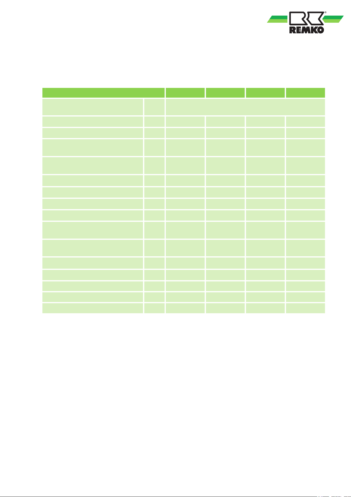
2 Technical data
2.1 Unit data
Series ML 265 DC ML 355 DC ML 525 DC ML 685 DC
Operating mode
Nominal cooling output
Energy efficiency ratio SEER
1)
1)
Electrical rated power consumption,
cooling
1)
kW
kW 0.75 1.05 1.46 2.40
Electrical rated current consumption,
cooling
Power consumption, annual, QCE
Energy efficiency ratio, cooling
Nominal heat capacity
Energy efficiency ratio SCOP
Electrical rated power consumption,
heating
1)
3)
kWh 128 175 290 394
1)
2)
4)
2)
kW
kW 0.72 1.05 1.45 2.18
Electrical rated current consumption,
heating
Power consumption, annual, QHE
Energy efficiency ratio, heating
2)
3)
kWh 875 922 1365 1785
2)
Inverter wall-mounted room air conditioner combination for
cooling and heating
2.6 (0.9-3.2) 3.5 (0.8-4.2) 5.3 (1.7-6.2) 7.2 (2.6-8.4)
7.1 7.5 6.7 6.4
A 3.25 4.74 6.35 10.55
A++ A++ A++ A++
2.6 (0.9-3.7) 2.8 (0.8-4.8) 5.3 (1.1-7.0) 5.1 (1.5-9.4)
4.0 4.2 4.0 4.0
A 3.44 4.5 6.4 9.5
A+ A+ A+ A+
Max. power consumption kW 2.1 2.2 2.6 3.6
Max. current consumption A 9.5 10.0 11.5 16.0
EDP no. 1635265 1635355 1635525 1635685
1)
Air inlet temp. TK 27 °C/FK 19 °C, outside temperature TK 35 °C, FK 24 °C, max. air flow volume,
5 m pipe length
2)
Air inlet temp. TK 20 °C, outside temperature TK 7 °C, FK 6 °C, max. air flow volume, 5 m pipe length
3)
The specified value is based on results from standard testing.
The actual consumption depends on the use and location of the unit
4)
The specified value is based on the average heating period
9
Page 10
REMKO ML series
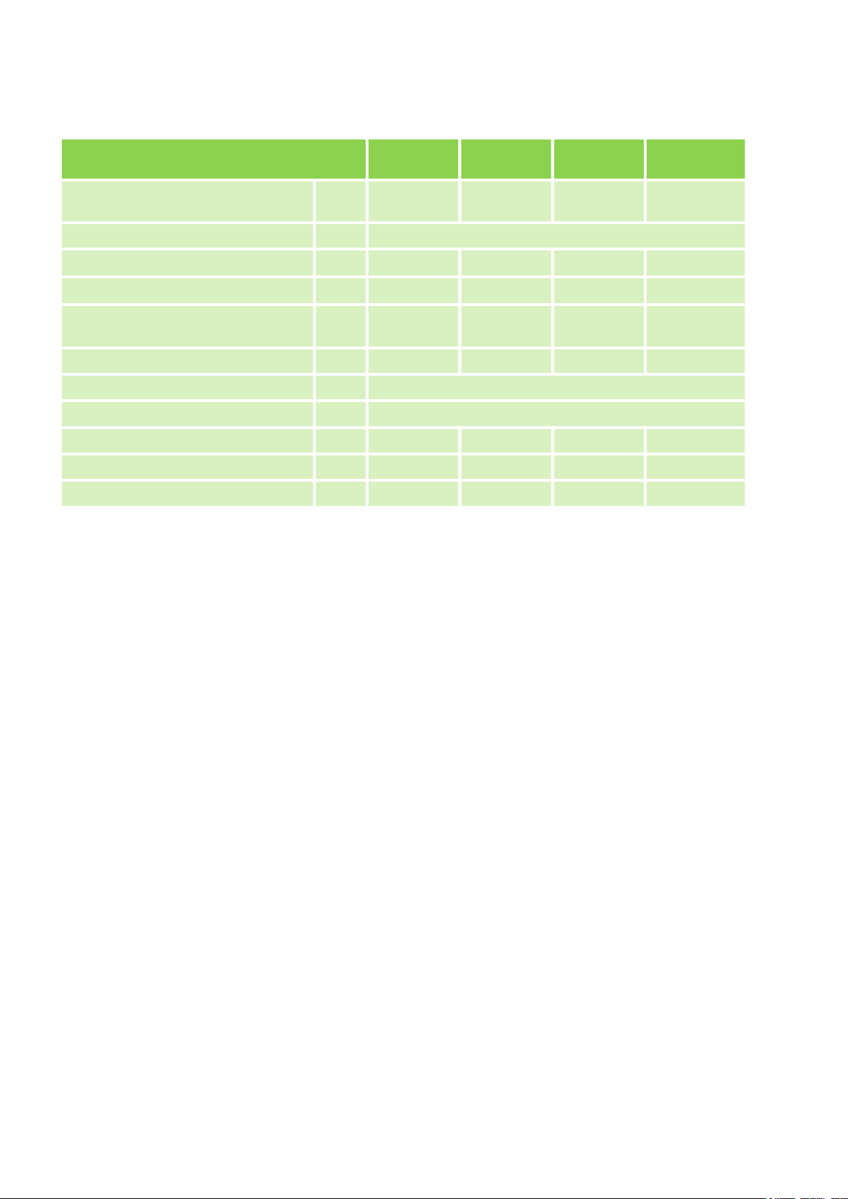
Data specific to indoor unit
Application area
(room volume), approx.
Adjustment range, room temperature °C +17 to +30
Air flow volume per stage
Sound pressure level per stage
Sound pressure level,
Silent/T
Sound power level max. dB(A) 53 55 57 62
Enclosure class IP X0
Condensate drainage connection mm 16
Dimensions: H/W/D mm 290/722/187 297/802/189 319/965/215 335/1080/226
Weight kg 7.4 8.2 9.0 12.9
EDP no. 1635267 1635357 1635527 1635687
5)
At distance of 1 m in the open air; specified values are maximum values
urbo mode
5)
5)
m
m3/h
dB(A) 22/30/37 22/30/38 27/33/42 30/44/44
dB(A) 20/39 21/41 26/45 26/46
ML 265 DCITML 355 DCITML 525 DCITML 685 DC IT
3
80 110 160 230
259/429/521 294/478/539 420/505/750 640/830/1020
10
Page 11
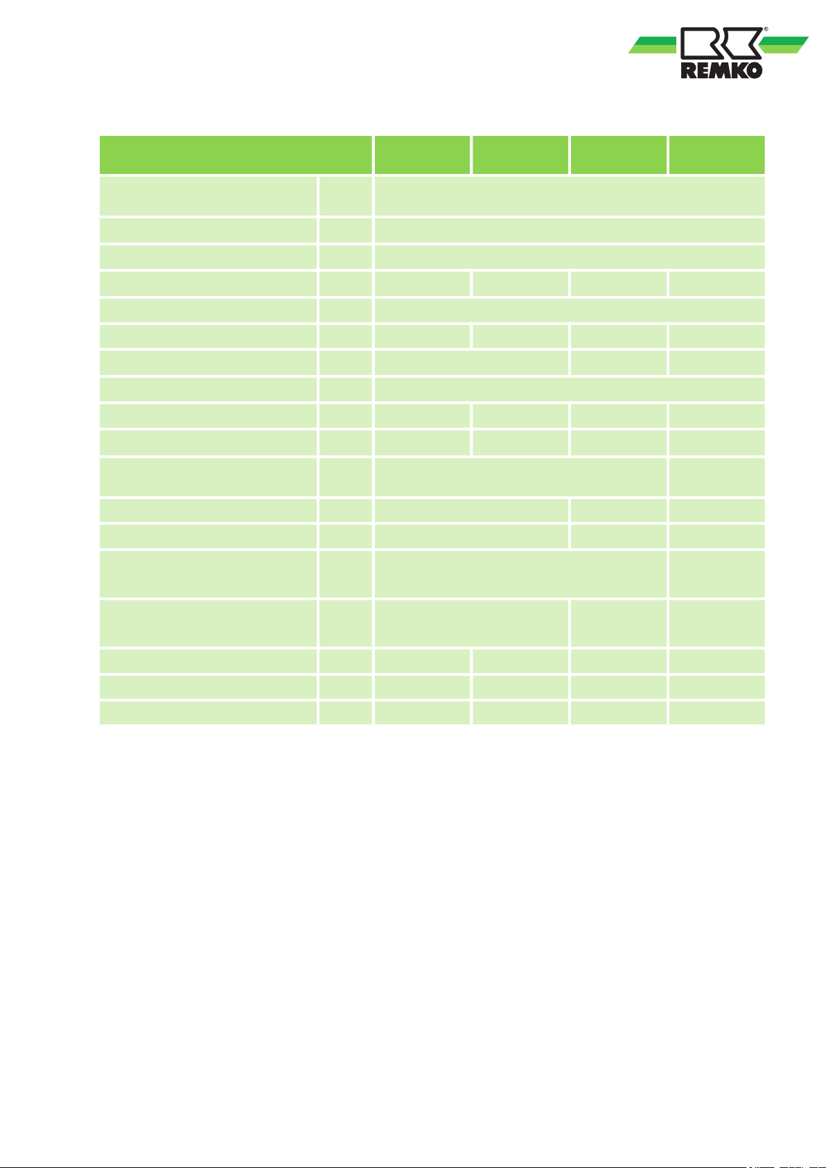
Data specific to outdoor unit
Power supply
Operating range, cooling
Operating range, heating
7)
8)
Air flow rate, max.
ML 265 DC
A
T
V/Ph/H
z
°C +5 to +30
°C +5 to +50
m3/h
2000 2000 2100 2700
ML 355 DCATML 525 DCATML 685 DC
AT
230/1~/50
Enclosure class IP 20
Sound power level max. dB(A) 58 60 64 66
Sound pressure level
Refrigerant
6)
5)
dB(A) 55 58 59
R32
Refrigerant, basic quantity kg 0.70 0.80 1.25 1.60
CO2 equivalent t 0.47 0.54 0.84 1.08
Refrigerant,
additional quantity >5 m
g/m 20 40
Refrigerant piping, max. length m 25 30 50
Refrigerant piping, max. height m 10 20 25
Refrigerant connection,
injection pipe
Refrigerant connection, suction
pipe
Inches
1/4 (6.35) 3/8 (9.52)
(mm)
Inches
3/8 (9.52) 1/2 (12.7) 5/8 (15.9)
(mm)
Dimensions: H/W/D mm 555/770/300 555/770/300 554/800/333 702/845/363
Weight kg 26.4 26.5 37.0 50.0
EDP no. 1635266 1635356 1635526 1635686
5)
At distance of 1 m in the open air; specified values are maximum values
6)
Contains greenhouse gas according to Kyoto protocol, GWP 675
7)
Expandable to -15 °C with WRK-1
8)
Expandable to -20 °C with WRH-1
11
Page 12
B
C
D
A
E
B
A
C
REMKO ML series
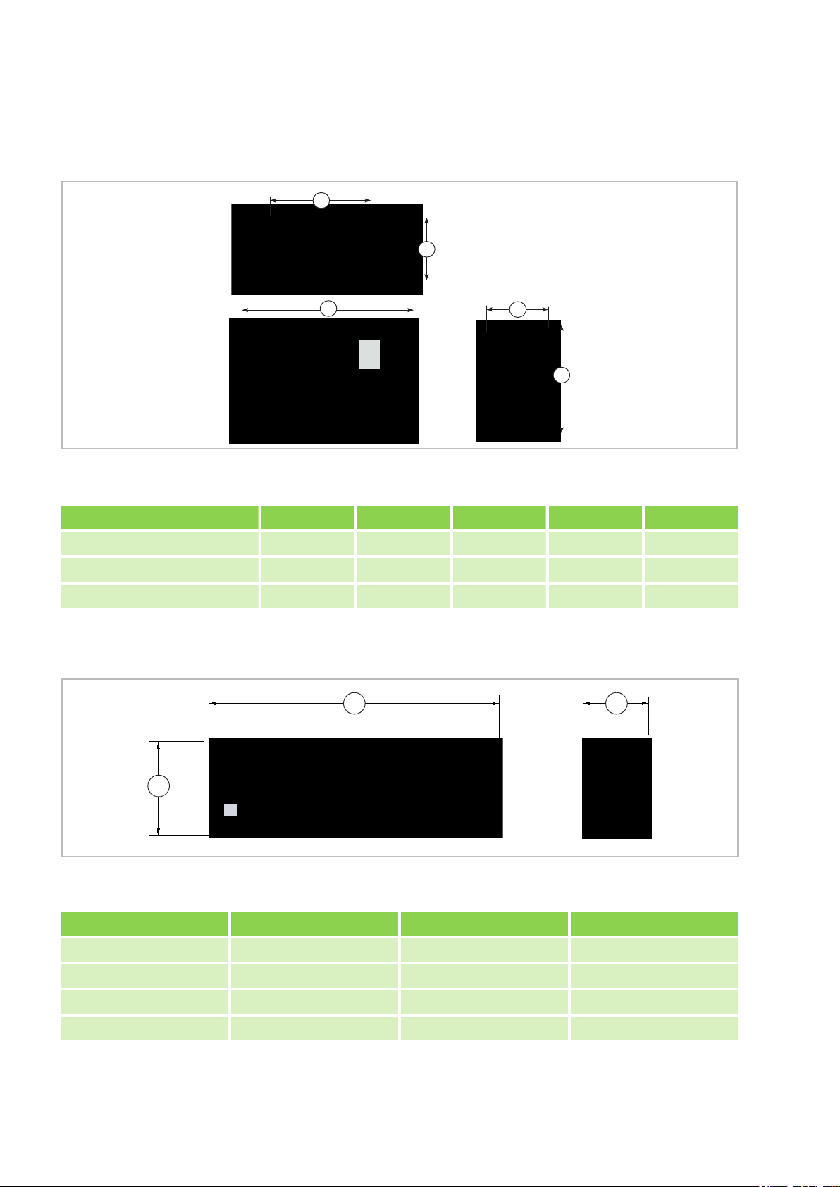
2.2 Unit dimensions
Outdoor units
Fig. 1: Outdoor unit ML 265 DC-685 DC AT dimensions
Measurements (mm) A B C D E
ML 265 DC-355 DC AT 770 487 298 555 300
ML 525 DC AT 800 514 340 554 333
ML 685 DC AT 845 540 350 702 363
Indoor units
Fig. 2: Indoor unit dimensions ML 265 DC-685 DC IT(All measurements in mm)
Measurements (mm) A B C
ML 265 DC IT 290 722 187
ML 355 DC IT 297 802 189
ML 525 DC IT 319 965 215
ML 685 DC IT 335 1080 226
We reserve the right to modify the dimensions and design as part of the ongoing technical development
process.
12
Page 13
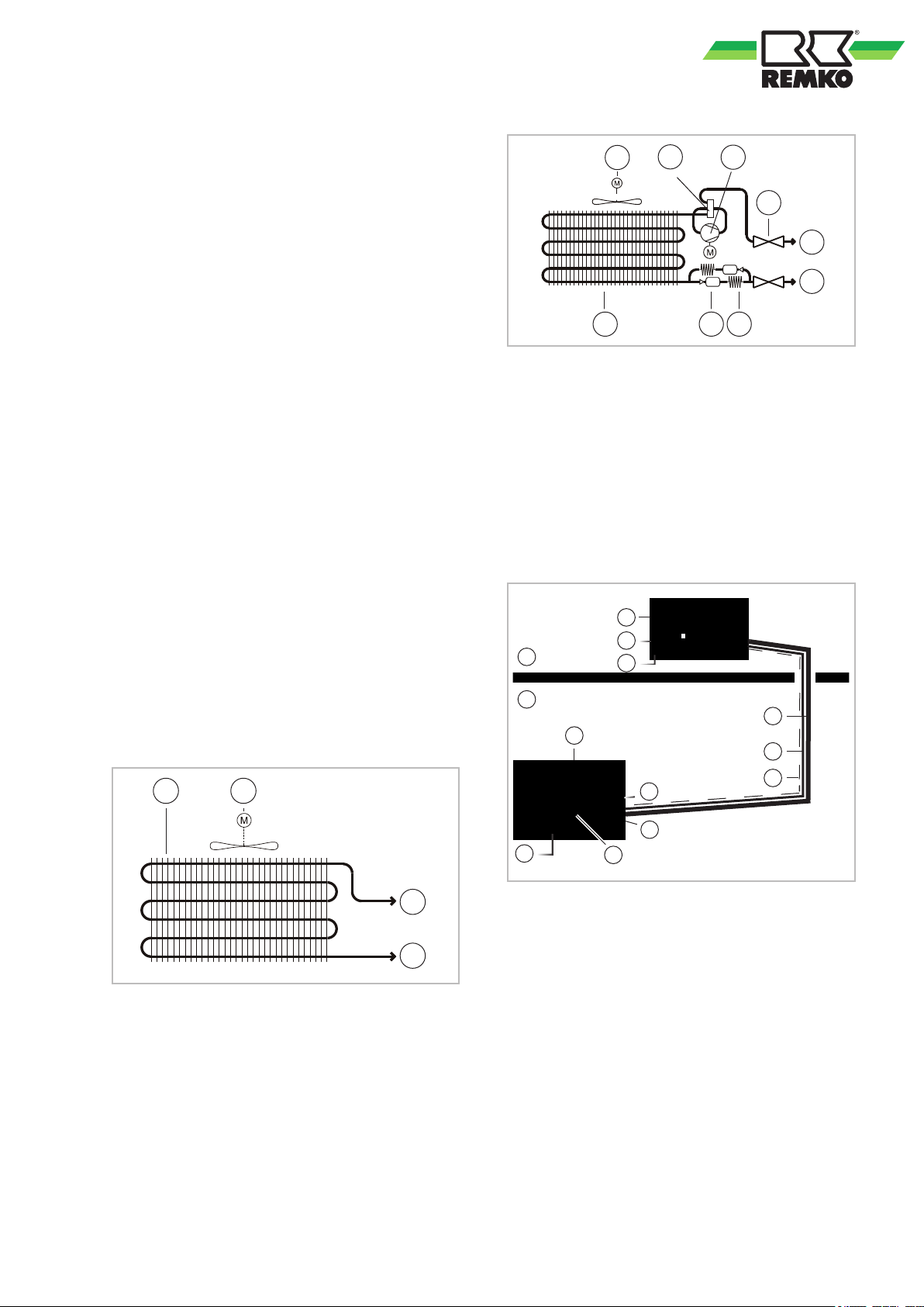
3 Design and function
21
4
3
2
1
4
3
5
7
8
9
6
1
7
8
9
B
A
4
3
5
6
2
3
5
3.1 Unit description
The ML series room air conditioners have a
REMKO ML...AT outdoor unit as well as an ML...IT
indoor unit.
In cooling mode, the outdoor unit serves to output
the heat extracted by the indoor unit from the room
being cooled. In heating mode, the heat taken up
by the outdoor unit can be discharged by the
indoor unit into the room to be heated. In both
operating modes, the output produced by the compressor precisely matches requirements, and
thereby regulates the nominal temperature with
minimal temperature deviations. This "inverter
technology" results in energy savings over conventional split systems and also reduces noise emissions to a particularly low level. The outdoor unit
can be installed in an outdoor area or, providing
that certain requirements are met, an indoor area.
The indoor unit is designed to be mounted high up
on the wall, in indoor areas. It is operated by an
infrared remote control.
The outdoor unit consists of a cooling cycle with
compressor, fin condenser, condenser fan,
reversing valve and throttle element. The outdoor
unit is controlled by the regulation of the indoor
unit.
The indoor unit consists of a fin evaporator, evaporator fan, controller and condensate tray.
Floor brackets, wall brackets, refrigerant piping and
condensate pumps are available as accessories.
Fig. 4: Cooling cycle diagram for outdoor unit
1: Condenser
2: Condenser fan
3: Reversing valve
4: Compressor
5: Filter dryer
6: Capillary tube throttle element
7: Pressure gauge connection
8: Suction pipe connection valve
9: Liquid line connection valve
Fig. 5: System layout
A: Outdoor area
B: Indoor area
1: Indoor unit
2: Outdoor unit
Fig. 3: Cooling cycle diagram for indoor unit
1: Evaporator
2: Evaporator fan
3: Suction pipe connection
4: Liquid pipe connection
13
3: Condensate drainage line
4: Condenser fan
5: Power supply cable
6: Shut-off valve
7: Suction pipe
8: Liquid line
9: Control line
Refrigerant piping is used to connect the indoor
unit to the outdoor unit.
Page 14
max. 6 m
1
REMKO ML series
4 Operation
4.1 General notes
The indoor unit is easily operated using the
standard infrared remote control. The indoor unit
beeps to acknowledge the correct transmission of
data. If it is not possible to program the indoor unit
with the remote control, then it can also be manually operated.
Alarms are indicated by a code (see chapter
T
roubleshooting and customer service).
NOTICE!
Manual mode
The indoor unit can also be switched on manually
if the infrared remote control is lost/defective.
Manual operation is intended for emergency operation and is not suitable for basic unit operation.
Please replace the remote control. The key for
manual activation is located below the housing
cover on the right side.
The following settings apply for manual operation:
Pressing once: Automatic mode,
Pressing twice: Cooling mode,
Pressing three times: Unit OFF
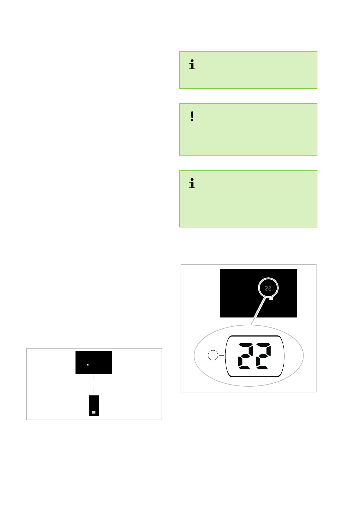
Infrared remote control
The infrared remote control sends the programmed
settings a distance of up to 6 m to the receiver of
the indoor unit. Data will only be received correctly
if the remote control is pointed at the receiver and
no objects are obstructing the transmission path.
wo AAA batteries must be inserted into the
T
remote control in preparation. To do so, remove
the flap from the battery compartment and insert
the batteries the correct way around (see markings). Removing the batteries causes all stored
data to be lost. The remote control will then access
the default settings, which you are free to customise at any time.
Immediately replace flat batteries with a new
set, otherwise there is a risk of leakage. It is
recommended that the batteries are removed if
the equipment is shut down for longer periods.
Help save on energy consumption in stand-by
mode! If the device, system or component is not
in use, we recommend disconnecting the power
supply
. Components with a safety function is
excluded from our recommendation!
4.2 Display on indoor unit
Display
Fig. 6: Maximum distance
Fig. 7: Display
1: Display of coded error message and target
temperature
14
Page 15
6
8
11
147
9
10
12
13
2
1
4
3
5
1
2
3
4
5
6
7
8
9
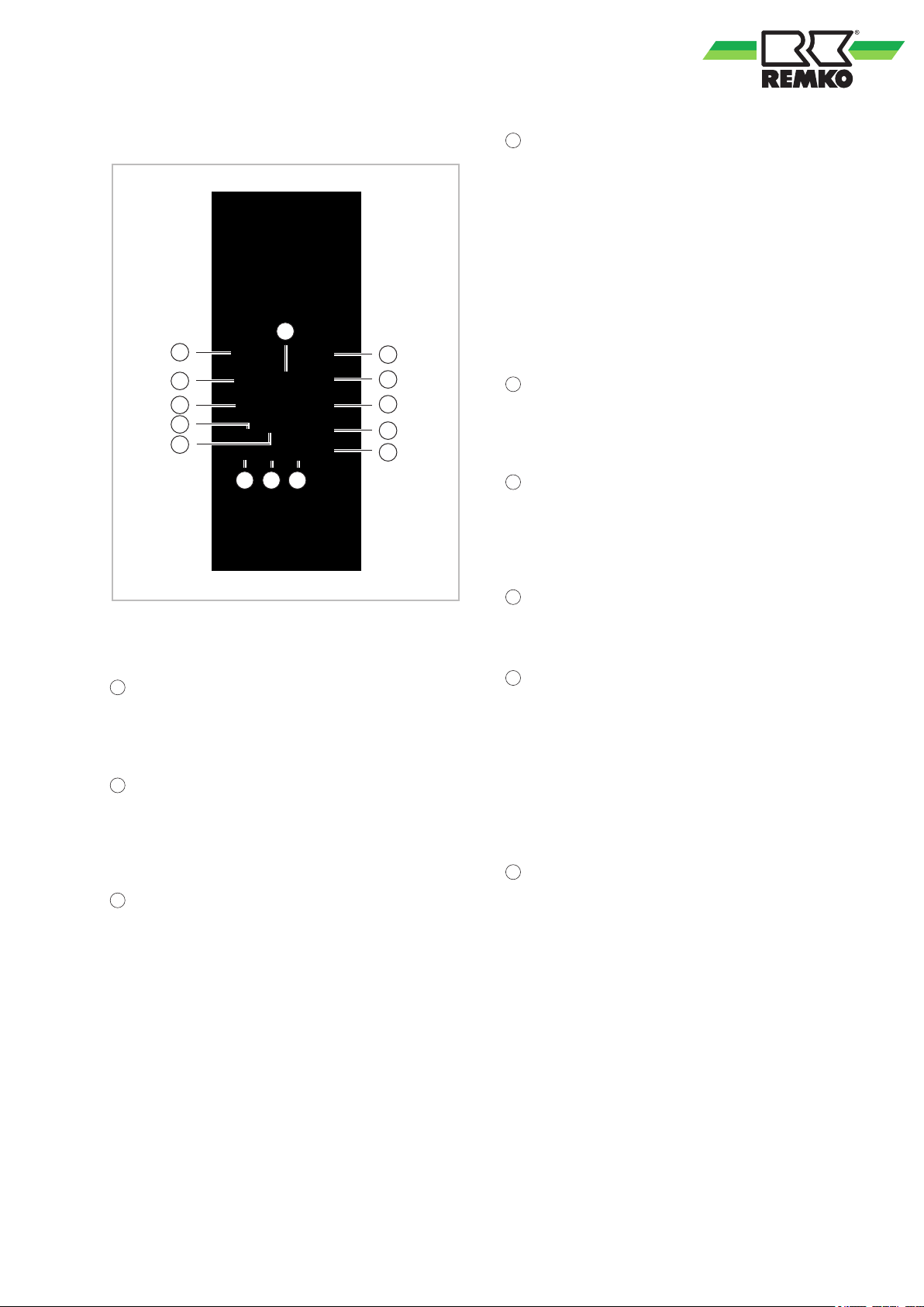
4.3 Keys on the remote control
"SLEEP" key
Activates/deactivates the "SLEEP" function.
Pressing this key will automatically increase or
decrease the target temperature by 1 °C within an
hour in cooling and heating mode respectively
.
Press this key to maintain the most convenient
temperature and save energy. This function is only
available in "Cooling", "Heating" and "Auto" modes.
If the unit is working in "SLEEP" mode, this activity
is interrupted by pressing the "MODE", "FAN",
"Speed" or "ON/OFF" keys.
"FRESH" key
Press this key to activate/deactivate the ion generator (air freshener).
"TURBO" key
Activation of the turbo function makes it possible to
reach the setpoint in cooling or heating mode as
fast as possible.
Fig. 8: Keys on the remote control
"ON/OFF" key
Press this key to switch the air conditioning unit on
f.
and of
Operating mode selection
This key is used to set the desired operating mode.
The automatic, cooling, dehumidification, heating
and recirculation modes are available.
Fan speed
Use this key to select the desired fan speed. The
automatic, low, medium and high functions are
available. Note: In the dehumidification mode, the
fan speed cannot be set manually.
"SELF CLEAN" key (not available)
This activates the self-clean function on the unit.
“ARROW UP” and “ARROW DOWN” keys
“ARROW UP” key
Press the key in order to increase the setpoint in 1
°C steps to a maximum 30°C.
“ARROW DOWN” key
Press the key in order to reduce the setpoint in 1°C
steps to a minimum 17°C.
“SILENCE/FP” key
Activates/deactivates the silent mode. Pressing the
key for longer than 2 seconds activates the unit's
frost protection function.
In silent unit mode, the compressor runs at a lower
frequency
, and the indoor unit fan rotates at a
slower speed. This obtains particularly silent unit
operation.
The frost protection function can only be activated
in heating mode. The unit operates with a fixed
setpoint of 8°C. The indoor unit displays "FP".
Pressing the ON/OFF, SLEEP, FP, Mode, FAN or
up or down arrow key, the frost protection function
is deactivated.
15
Page 16
10
11
12
13
14
2
1
4
3
6
9
8
10
5
7
11
13 12
REMKO ML series
"TIMER ON" key
Press this key to activate the unit start delay time.
Each press of this key increases the delay time by
30 minutes. When the set time on the display
exceeds 10.0, each press of the button increases
the set time by 60 minutes. T
o deactivate the delay
time, set the time to 0.0.
"TIMER OFF" key
This key can be used to program the delayed
switch-of
f time. Each press of this key increases
the switch-off time by 30 minutes. When the set
time on the display exceeds 10.0, each press of
the button increases the set time by 60 minutes. To
deactivate the switch-off time, set the time to 0.0.
3-D swing mode
Press this key to start or stop the swing mode.
With the 2-point key
, you can adjust the horizontal
fin on the left side and the vertical fin on the right
side. Press this key once to change the angle by 6
degrees. Pressing the key for 2 seconds stops the
swing function. When the swing function is
stopped, LC appears on the display for three seconds.
"FOLLOW ME" key
This key can be used to activate/deactivate the
FOLLOW ME function. In this mode, the room temperature is measured on the remote control. This
sends a signal to the indoor unit every 3 minutes. If
the remote control does not send a signal to the
indoor unit for 7 minutes, this mode is automatically deactivated.
"LED" key
This activates/deactivates the display on the indoor
unit.
Indicators on the LCD
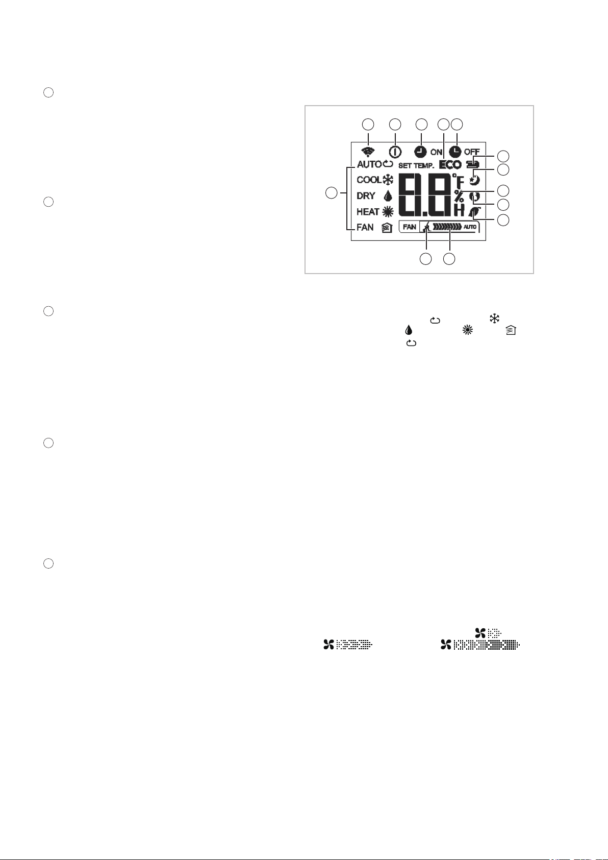
Fig. 9: Indicators on the LCD
1: Mode indicator - shows the current operating
modes, including Auto ( ), Cooling ( ),
Dehumidification ( ), Heating ( ), Fan ( )
and back to Auto ( ) mode.
2: Signal transmission symbol. This symbol
appears when signals are being transmitted
from the remote control to the indoor unit.
3: ON/OFF symbol. This symbol appears when
the "ON/OFF" key is pressed. Pressing this
key again causes the indicator to go out.
4: TIMER ON symbol. This symbol appears
when TIMER ON is switched on.
5: ECO function (not available)
6: TIMER OFF symbol. This symbol appears
when TIMER OFF is switched on.
7: Battery charge status (weak)
8: Sleep symbol. This symbol appears when the
"Sleep" function is activated. Pressing this key
again causes the indicator to go out.
9: Temperature/Timer symbol. Shows the tem-
perature setting (-17°C~30°C). If "F
AN" mode
is selected, the temperature setting is not displayed. In Timer mode, the ON and OFF settings appear for the TIMER.
10: FOLLOW ME symbol. This symbol appears
when the "Follow me" function is activated.
11: Display of ion generator active (optional)
12: Fan speed symbol. This is where the selected
fan speeds are displayed: AUTO (no indicator)
and the three fan speed settings:
(slow),
(medium) and
(fast). The fan speed is set to "Automatic"
when either "Auto" or "Dehumidification" mode
is activated.
13: Silent mode active (optional)
16
Page 17
1
3
2
1
4
2
3
The illustration of the LCD with all of the symbols present is only intended to provide a
clearer overview
. During operation, only those
symbols relevant to the respective functions
appear on the display.
Key functions
A symbol is shown on the display to indicate that
the settings are being transferred.
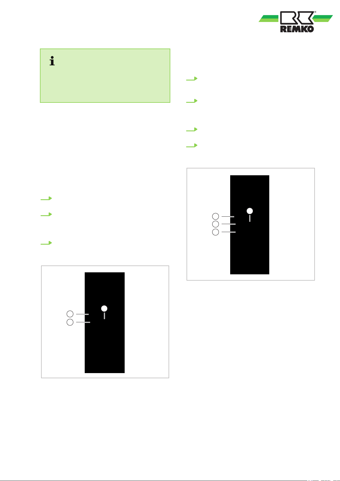
“Auto” mode (please observe notes!)
Make sure that the indoor unit is connected to the
power supply
, and is switched on.
The operating mode indicator on the display of the
indoor unit begins to flash.
1. Press the "MODE" key to select "Auto"
mode.
2. Press the "Arrow up/down" key to set the
desired temperature. The temperature can
be set between 17 and 30°C, in increments
of 1°C.
3. Press the "ON/OFF" key to switch on the air
conditioning unit.
"Cooling", "Heating" and "Recirculation" mode
Make sure that the indoor unit is connected to the
power supply
, and is switched on.
1. Press the "MODE" key to select from operating modes "Cooling", "Heating" or "Recirculation".
2. Press the "Arrow up/down" key to set the
desired temperature. The temperature can
be set between 17 and 30°C, in increments
of 1°C.
3. Press the "F
AN" key to select from the four
fan speeds (Auto, slow, medium and fast).
4. Press the "ON/OFF" key to switch on the air
conditioning unit.
Fig. 10: "Auto" mode
Fig. 11: "Cooling", "Heating" and "Recirculation"
mode
17
Page 18
1
3
2
2
1
REMKO ML series
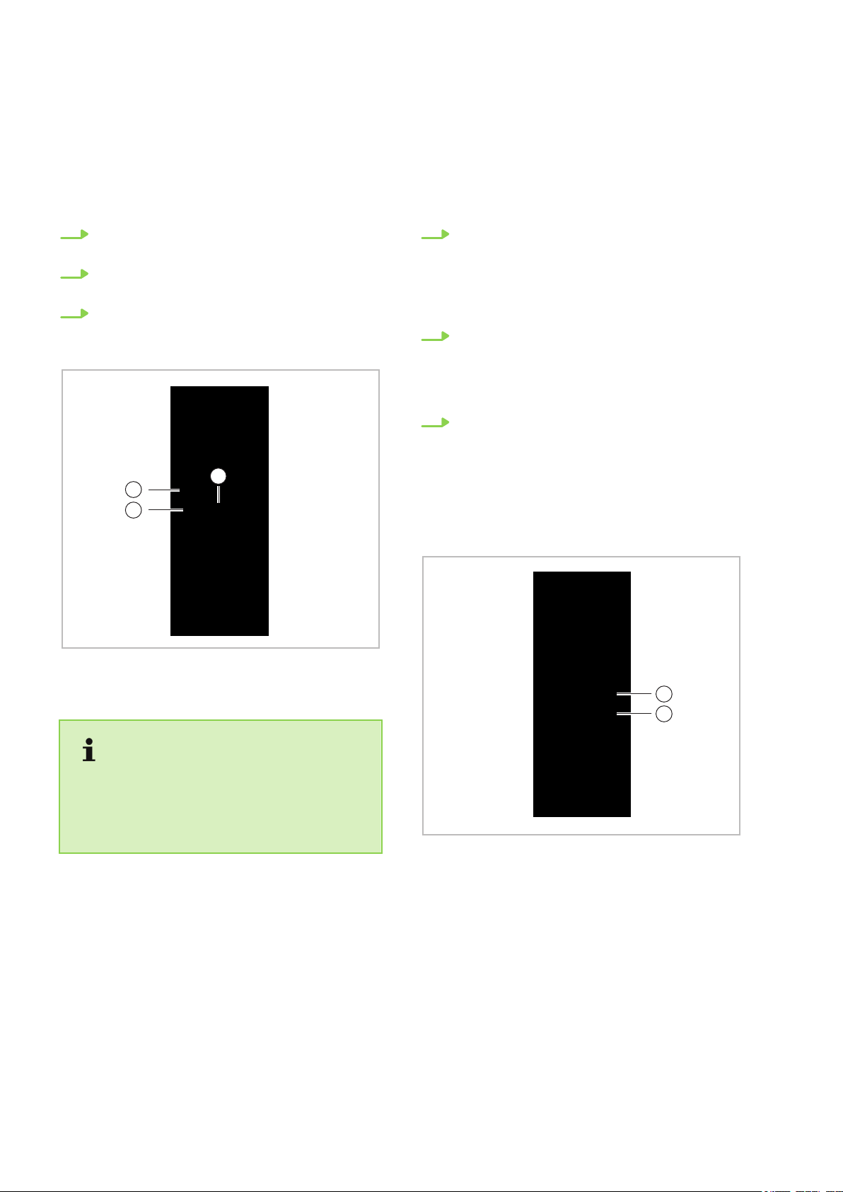
"Dehumidification" mode
Make sure that the indoor unit is connected to the
power supply
The operating mode indicator on the display of the
indoor unit begins to flash.
1. Press the "MODE" key to select "Dehumidification" mode.
2. The temperature setting on the remote control has no ef
3. Press the "ON/OFF" key to switch on the air
conditioning unit.
, and is switched on.
fect on unit operation.
"Timer" mode
Press the "TIMER ON" key to set the "switch-on
time" and the "TIMER OFF" key to set the "switchof
f" time for the unit.
Setting the “switch-on time”
1. Press the "TIMER ON" key
trol shows "TIMER ON", the last "switch-on
time" setting and the symbol "H" appear on
the display. The unit is now ready to reset the
"switch-on time" and to start "TIMER ON"
mode.
2. Press the "TIMER ON" key again to set the
desired "switch-on time". Each time the key
is pressed, the time is increased by half an
hour between 0 and 10 hours, and by an
hour between 10 and 24 hours.
3. Once these settings have been made, there
is a one second delay before the remote control transmits the signal to the indoor unit.
Then, after approx. two seconds, the "H"
symbol disappears from the LCD display
the set temperature appears again on the
display.
. The remote con-
, and
Fig. 12: "Dehumidification" mode
In the “Dehumidification” mode, manual selection of the fan speed is not possible! Please
note that temperature pre-selection is not possible and the dehumidified room can cool dramatically!
Fig. 13: "Timer" mode
18
Page 19
Start
Off
2 hours laterSet time
Stop
On
4 hours laterSet time
Setting the “switch-off time”
1. Press the "TIMER OFF" key
. The remote
control shows "TIMER OFF", the last "switchoff time" setting and the symbol "H" appear
on the display. The unit is now ready to reset
the "switch-off time" and to stop "TIMER
OFF" mode.
2. Press the "TIMER OFF" key again to set the
desired "switch-of
f time". Each time the key
is pressed, the time is increased by half an
hour between 0 and 10 hours, and by an
hour between 10 and 24 hours.
3. Once these settings have been made, there
is a one second delay before the remote control transmits the signal to the indoor unit.
Then, after approx. two seconds, the "H"
symbol disappears from the LCD display
, and
the set temperature appears again on the
display.
– When T
imer mode is selected, the remote
control automatically transfers the timer
signal to the indoor unit for the specified
period of time. Therefore, you should hold
the remote control in a location where it can
transfer the signal to the indoor unit without
interference.
– The effective operation for the time settings
by the remote control for the timer function
is restricted to the following settings:
0.5, 1.0, 1.5, 2.0, 2.5, 3.0, 3.5, 4.0, 4.5, 5.0,
5.5, 6.0, 6.5, 7.0, 7.5, 8.0, 8.5, 9.0, 9.5, 10,
11, 12, 13, 14, 15, 16, 17, 18, 19, 20, 21,
22, 23 and 24.
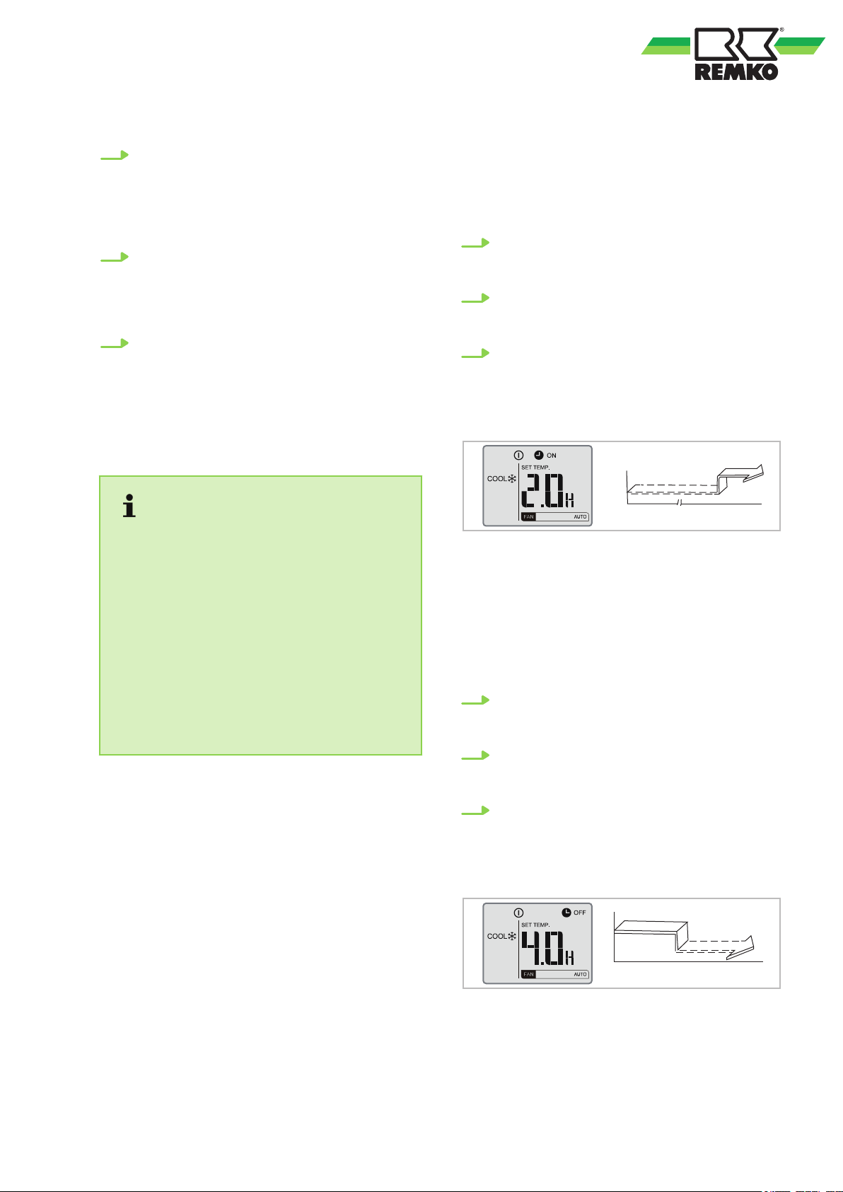
Example TIMER function settings
"TIMER ON" (Auto on mode)
Example:
Y
ou want the air conditioning unit to switch on 2
hours from the time it was programmed
1. Press the "TIMER ON" key
. The last operating time setting for the timer, and the "H"
symbols, appear on the display.
2. Press the "TIMER ON" key until the desired
start time is shown in the "TIMER ON" area
on the remote control.
3. W
ait for 3 seconds and the temperature
appears again in this area of the digital display. The "TIMER ON" indicator stays lit, and
this function is activated.
Fig. 14: "TIMER ON" example
"TIMER OFF" (Auto off mode)
Example:
ou want the air conditioning unit to switch off 4
Y
hours from the time it was programmed.
1. Press the "TIMER OFF" key
. The last operating time setting for the timer, and the "H"
symbols, appear on the display.
2. Press the "TIMER OFF" key until "4H" is
shown in the "TIMER OFF" area on the
remote control.
3. W
ait for 3 seconds and the temperature
appears again in this area of the digital display. The "TIMER OFF" indicator stays lit,
and this function is activated.
Fig. 15: "TIMER OFF" example
19
Page 20
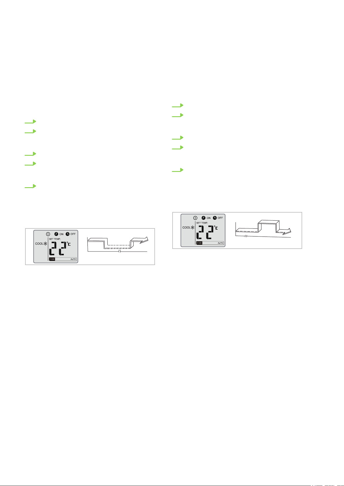
On
Set time
Stop
Start
2 hours later
after setting
10 hours later
after setting
Off
Set time
Stop
Start
2 hours later
after setting
5 hours later
after setting
REMKO ML series
Combined TIMER (setting "TIMER ON" and
"TIMER OFF" at the same time)
"TIMER OFF ð "TIMER ON"
(On ð Stop ð Start)
Example:
Y
ou want the air conditioning unit to switch off in
two hours from the time it was programmed, and
switch back on ten hours later.
1. Press the "TIMER OFF" key.
2. Press the "TIMER OFF" key again until the
desired stop time is shown in the "TIMER
OFF" area on the remote control.
3. Press the "TIMER ON" key.
4. Press the "TIMER ON" key again until "10H"
is shown in the "TIMER ON" area on the
remote control.
5. Wait for 3 seconds and the temperature
appears again in this area of the digital display. The "TIMER ON" and "TIMER OFF"
indicators stay lit, and this function is activated.
"TIMER ON ð
"TIMER OFF"
(Off ð Start ð Stop)
Example:
You want the air conditioning unit to switch on in
two hours from the time it was programmed, and
switch back off five hours later.
1. Press the "TIMER ON" key.
2. Press the "TIMER ON" key again until "2.0H"
is shown in the "TIMER ON" area on the
remote control.
3. Press the "TIMER OFF" key.
4. Press the "TIMER OFF" key again until
"5.0H" is shown in the "TIMER OFF" area on
the remote control.
5. Wait for 3 seconds and the temperature
appears again in this area of the digital display. The "TIMER ON" and "TIMER OFF"
indicators stay lit, and this function is activated.
Fig. 16: "TIMER OFF" / "TIMER ON" example
Fig. 17: "TIMER ON" / "TIMER OFF" example
20
Page 21
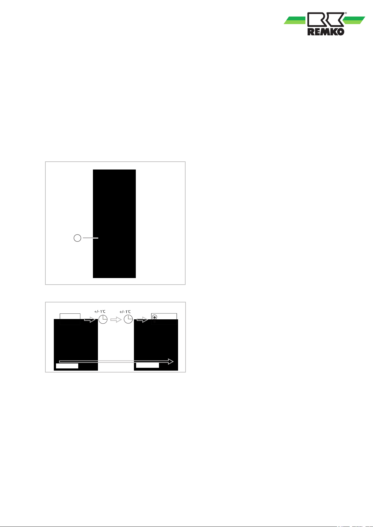
SLEEP function
1
Setpoint
After 7 hours
unit OFF
1 hr
1 hr
The sleep function saves energy while you sleep.
This function is activated by pressing the key on
the remote control. Press the key before going to
sleep. In cooling mode, the unit automatically
increases the set room temperature by 1 °C after 1
hour
. After one more hour, the room temperature is
increased by an additional 1 °C. In heating mode,
the room temperature is decreased within the first
two hours of operation by 2°C. After 7 hours of unit
operation, the unit switches off automatically in
cooling and heating mode.
This function is not available in the modes recirculation and dehumidification!
Fig. 18: "Sleep" function
Fig. 19: Sleep mode
21
Page 22
21 5
3 4
REMKO ML series
5 Installation Instructions for qualified personnel
5.1 Important notes prior to installation
ransport the unit in its original packaging as
n T
close as possible to the installation location.
You avoid transport damage by doing so.
n Check the contents of the packaging for com-
pleteness and check the unit for visible transport damage. Report any damage immediately
to your contractual partner and the shipping
company.
n Lift the unit on the corners and not on the
refrigerant or condensate drainage connections.
n The refrigerant piping (liquid and suction pipe),
valves and connections must be insulated to
make them vapour diffusion proof. If necessary
also insulate the condensate drainage line.
n Select an installation location which allows air
to freely flow through the air inlet and outlet
(see section "Minimum clearances")
n Do not install the unit in the immediate vicinity
of devices which generate intensive thermal
radiation. Installation in the vicinity of thermal
radiation reduces the unit output.
n Only open the shut-off valves on the refrigerant
piping after installation is complete.
n Seal off open refrigerant piping with suitable
caps or adhesive strips to prevent the infiltration of moisture and never kink or compress
the refrigerant piping.
n Avoid unnecessary bends. This minimises the
pressure loss in the refrigerant piping and
ensures that the compressor oil can flow back
without obstruction.
n Make special preparations regarding the oil
return if the outdoor unit is located above the
indoor unit (see section "Oil return measures").
n Add refrigerant if the basic length of the refrig-
erant piping exceeds 5 metres. For the quantity
of additional refrigerant, refer to chapter
"Adding refrigerant".
n Perform all electrical wiring in accordance with
applicable DIN and VDE standards.
n Ensure the electrical cables are properly con-
nected to the terminals, otherwise there is a
risk of fire.
n Only use the fasteners contained in the scope
of delivery with the units.
n Use four supports and the associated hooks to
attach the ceiling cassette (only applies to
ceiling cassettes).
n Use the insulated condensate hose in the
scope of delivery as a junction piece to the
continuing condensate drain. Secure the condensate drain with the supplied clamps.
5.2 Wall openings
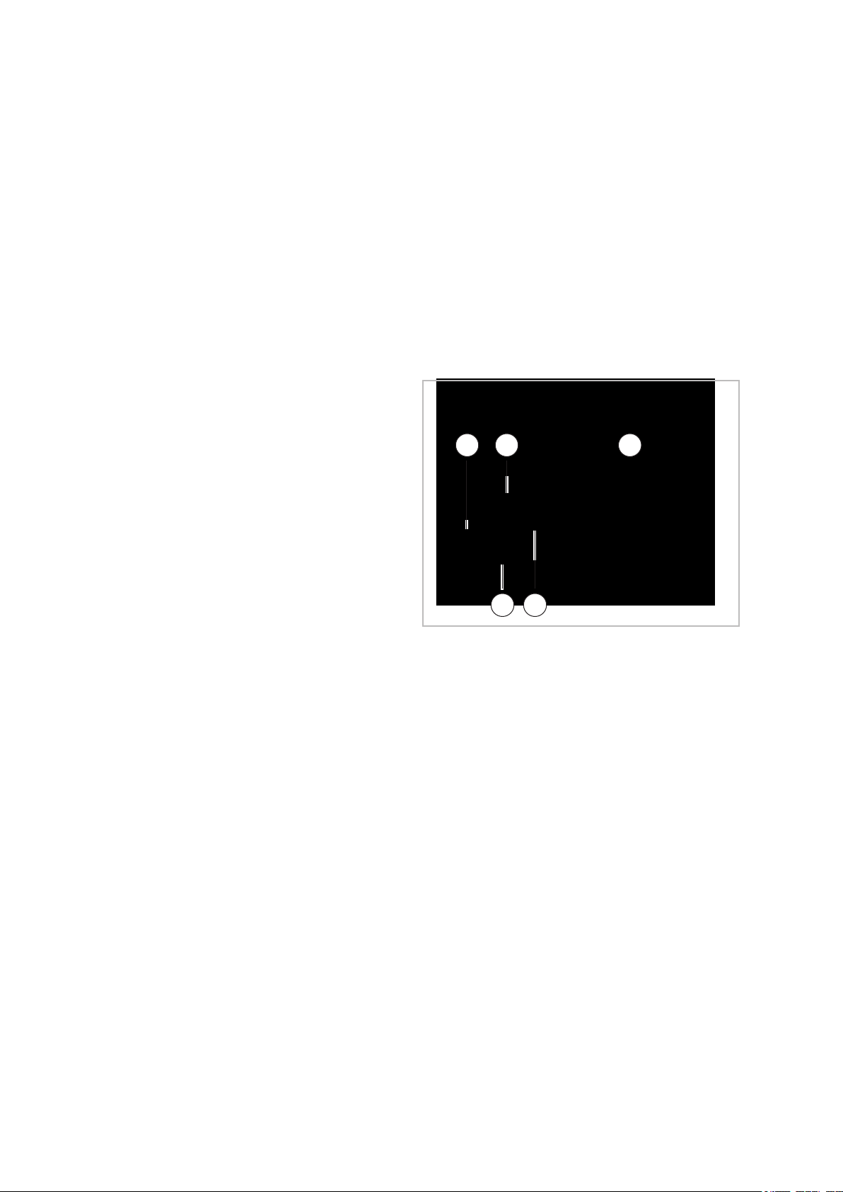
n A wall opening of at least 70mm diameter and
10mm incline from the inside to the outside
must be created.
o prevent damage to the lines, the interior of
n T
the wall opening should be padded or, for
example, lined with PVC pipe (see figure).
n After installation has been completed, use a
suitable sealing compound to close off the wall
opening, taking account of fire protection regulations (responsibility of customer). Do not use
cement or lime containing substances!
Fig. 20: Wall opening
1: Liquid line
2: Control line
3: Condensate drainage line
4: Suction pipe
5: PVC pipe
5.3 Installation materials
The indoor unit is attached to the wall by a wall
bracket and 4 screws (to be provided by the customer).
The outdoor unit is attached by 4 screws and a
wall bracket to the wall or fixed by a floor bracket to
the ground.
22
Page 23
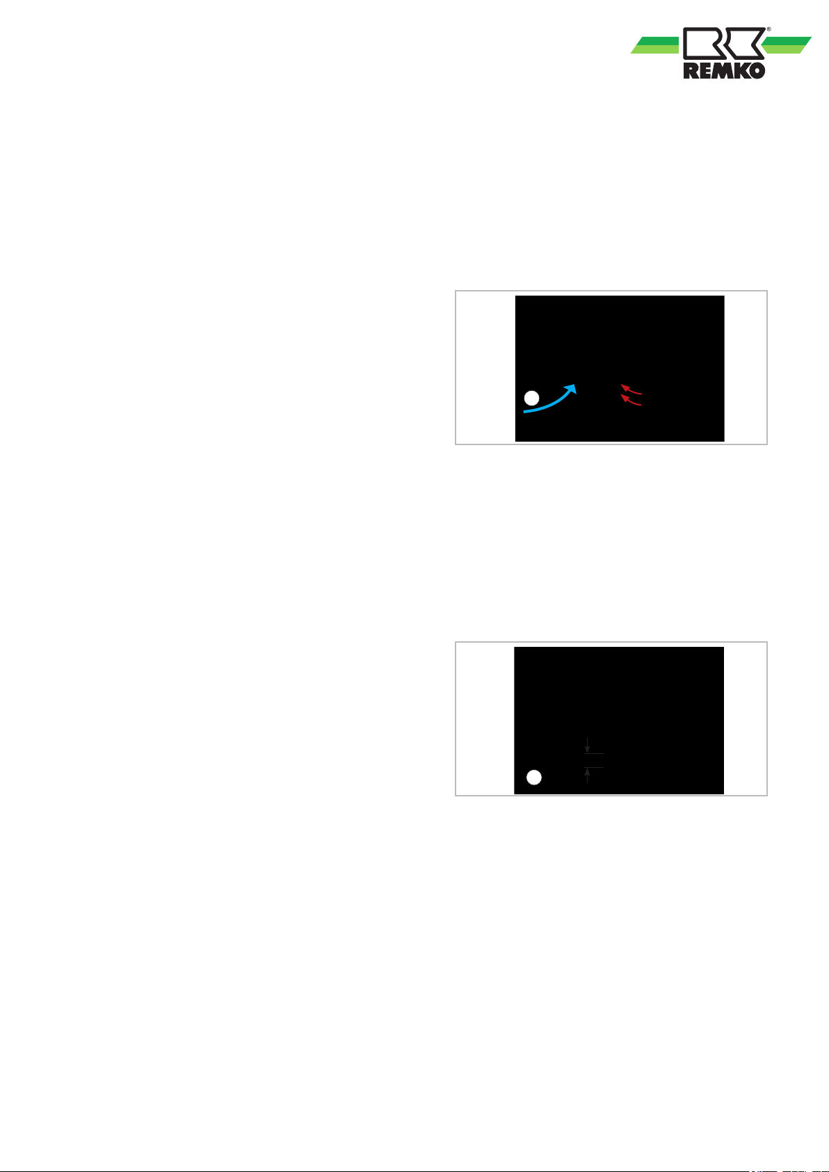
1
20 cm
1
5.4 Selection of installation
location
Indoor unit
The indoor unit is designed for horizontal wall
installation above doors. However
used in the upper wall area (min. 1.75m above the
floor).
Outdoor unit
The outdoor unit is designed for horizontal installation on a base in outdoor areas. The installation
site must be level, flat and firm. The unit should
also be secured to prevent it from tipping over. The
outdoor unit can be set up outside as well as inside
a building. For external installation, please observe
the following notes to protect the unit from the
influence of the weather.
Rain
For floor or roof set-up, the unit should be installed
with at least 10cm ground clearance. A floor
bracket is available as an optional accessory.
, it can also be
Wind
If the unit is being installed in windy areas, ensure
that the warm outlet air is discharged in the prevailing wind direction. If this is not the possible, it
may be necessary to install a windbreak (to be provided by the customer). Ensure that the windbreak
does not adversely affect the air intake to the unit.
An additional stabilization is recommended. This
can, for example, be realized with ropes or other
structures.
Fig. 21: Windbreak
1: Wind
Sun
The condenser on the outdoor unit emits heat.
Exposure to sunlight further increases the temperature of the fins and reduces the heat released by
the finned heat exchanger. The outdoor unit should
be installed on to the north side of the building
whenever possible. If necessary, take measures to
provide sufficient shade (responsibility of customer). One possible solution is to build a small
roofed area over the unit. These measures should
not affect the flow of warm outlet air.
Snow
The unit should be wall-mounted in areas of heavy
snowfall. Installation should be at least 20cm
above the expected level of snow to prevent snow
from entering the outdoor unit. An optional wall
bracket is available as an accessory
Fig. 22: Minimum clearance to snow
1: Snow
Installation inside buildings
n Ensure that heat can dissipate adequately
when placing the outdoor unit in cellars, lofts,
adjoining rooms or halls (
Fig. 23).
.
n Install an additional fan with a rated flow com-
parative to that of the outdoor unit being
installed in the room and which can compensate any additional pressure loss in ventilation
ducts (Fig. 23).
n Comply with any regulations and conditions
fecting the statics of the building. If neces-
af
sary, fit acoustic installation.
23
Page 24
2
1
K
3
W
3
2
1
2
1
A
B
C
D
E
E
C
A
B
F
IT AT
REMKO ML series
Fig. 23: Installation inside buildings
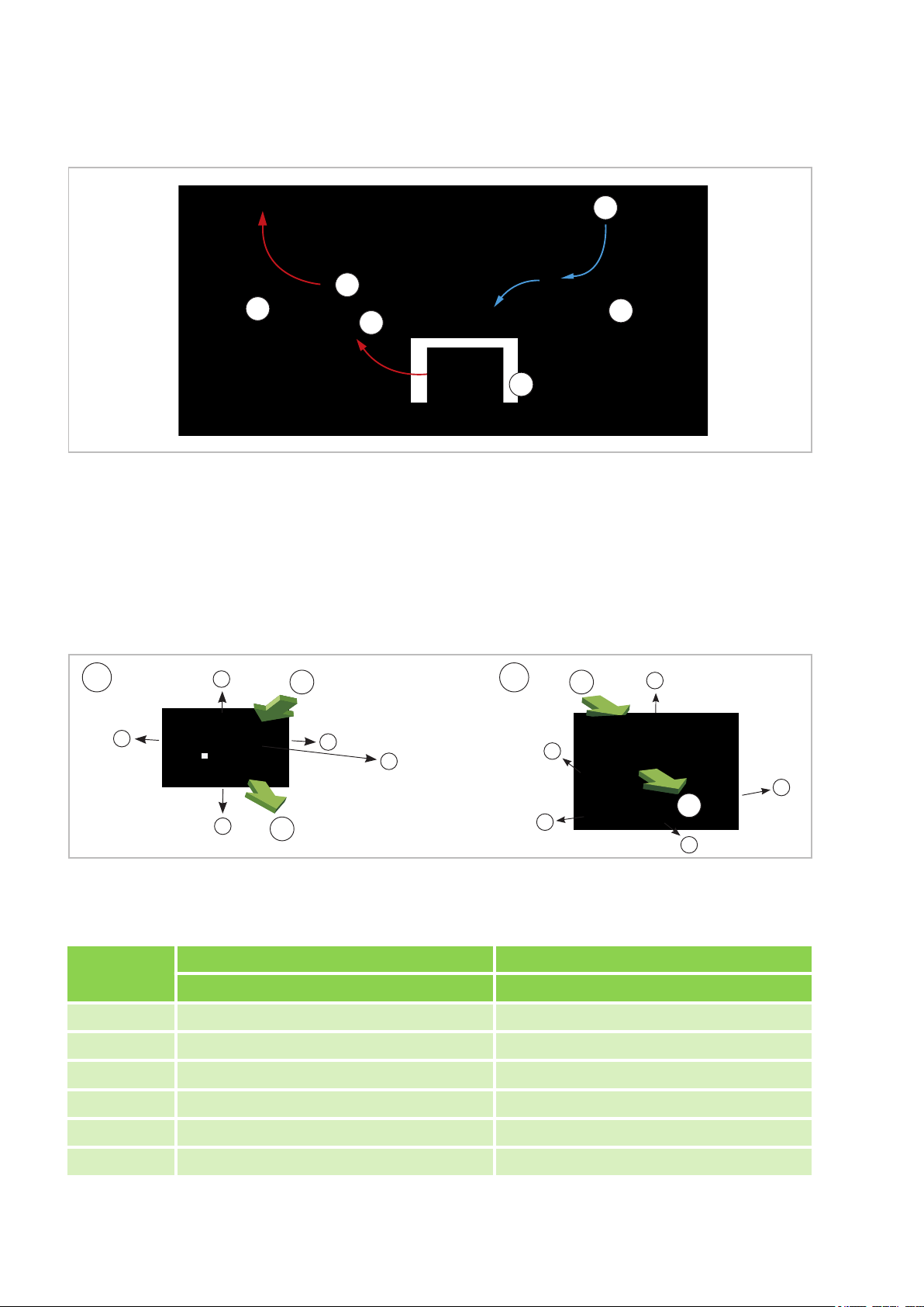
K: Cold fresh air / W: Warm air
1: Outdoor unit / 2: Additional fan
3: Air shaft
5.5 Minimum clearances
Observe the minimum clearances to allow access for maintenance and repair work and facilitate optimum air
distribution.
Fig. 24: Minimum clearances of the indoor unit and outdoor unit
AT: Outdoor unit / IT: Indoor unit 1: Air inlet / 2: Air outlet
Measure-
ments (mm)
A 120 150
Indoor units Outdoor units
ML 265 DC-685 DC IT ML 265 DC-685 DC AT
B 1500 700
C 120 400
D - 150
E 120 200
F 1700 -
24
Page 25
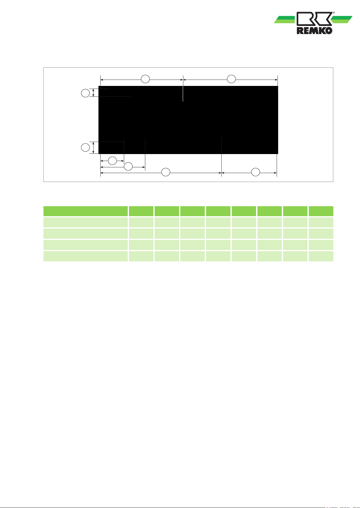
5.6 Wall bracket
A B
C
D
G
F
E
H
Fig. 25: Wall bracket for indoor units ML 265 DC-685 DC IT (rear view)
Measurements (mm) A B C D E F G H
ML 265 DC IT 372 350 37 50 100 197 542 180
ML 355 DC IT 375 427 43 44 111 204 545 257
ML 525 DC IT 543 423 53 55 111 135 821 144
ML 685 DC IT 527 553 53.5 47 44 219 780 300
25
Page 26
D
C
D
B
A
C
A
B
REMKO ML series
5.7 Connection variants for the indoor unit
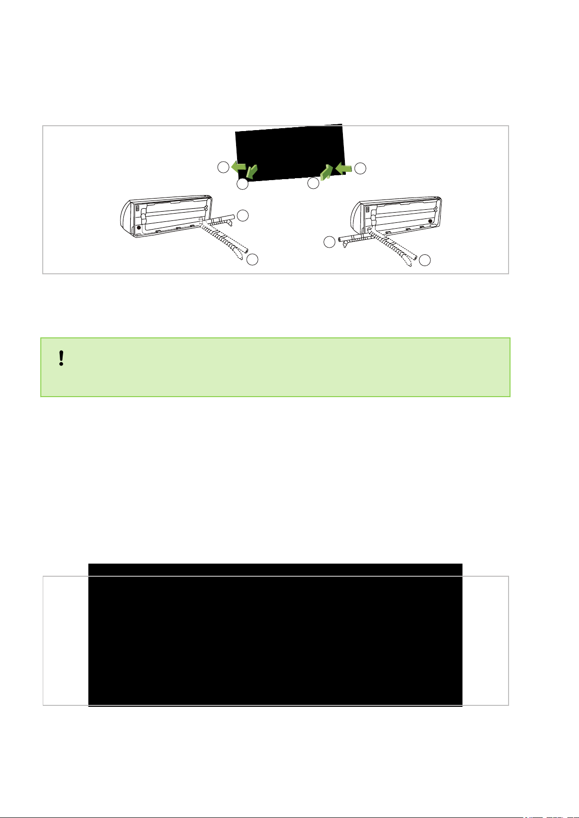
The following connection variants can be used for the refrigerant, condensate and control lines.
Fig. 26: Connection variant (view from the rear)
A: Infeed of the refrigerant piping at the wall, left
B: Infeed of the refrigerant piping through the wall,
left
C: Outlet through the wall, right
D: Outlet at the wall, right (the refrigerant piping
must be bent through 180 degrees for this)
NOTICE!
A flare connection may only be established outside the room. Detachable, reusable connections are not
permissible inside!
5.8 Connection of the indoor unit when the refrigerant piping is installed under the plaster
If the customer routes the refrigerant piping to the unit underneath the plaster, observe the following note.
The principal connection options can be found in the "Connection variants for the indoor unit" and "W
bracket" chapters.
If the refrigerant piping is routed underneath the plaster, ensure that the customer-fitted refrigerant piping
does not protrude from the wall at a 90° angle. As a result of the required bending radius, the unit would then
be very difficult to connect or would possibly be impossible to fasten to the wall mount.
For this reason, route the customer-fitted refrigerant piping with as flat an angle as possible (<30°) out of the
wall, from the left and into the unit. (see Fig. 27).
all
Fig. 27: Under the plaster installation (View from above)
26
Page 27
1
A
B
5.9 Oil return measures
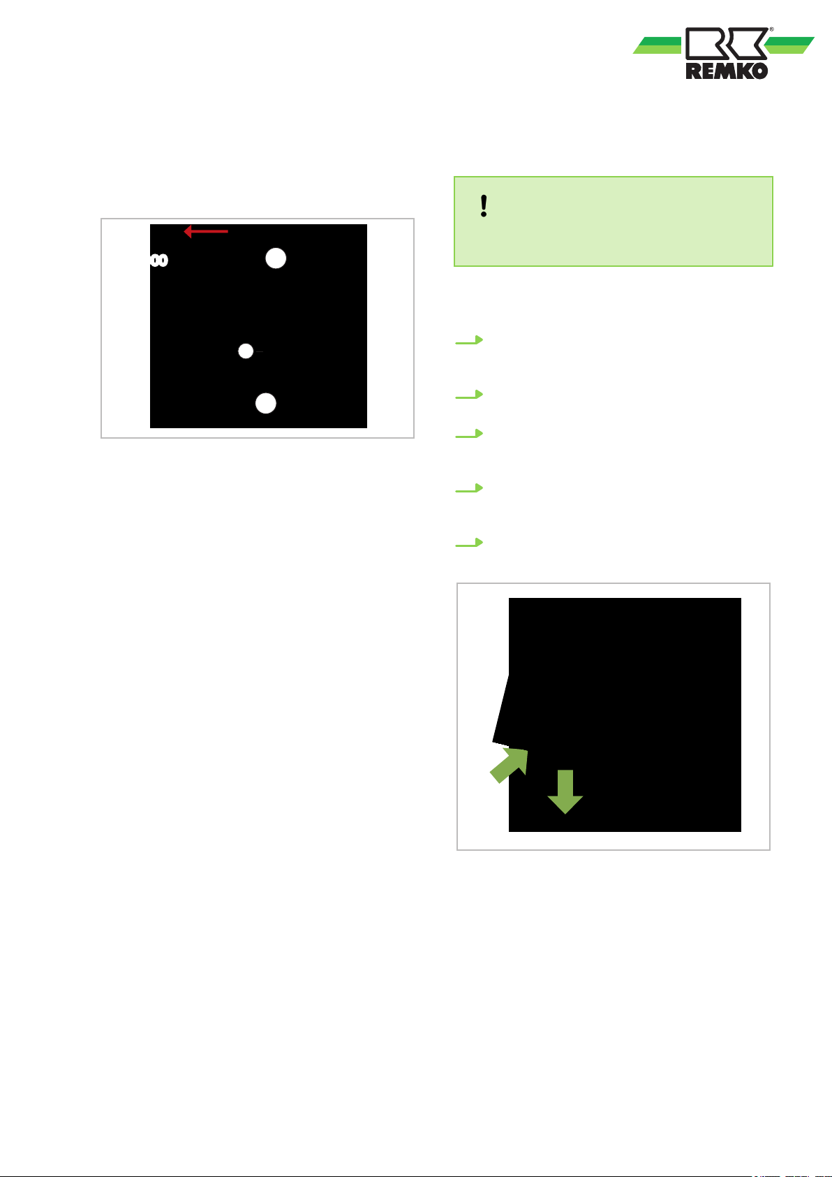
If the outdoor unit is installed at a higher level than
the indoor unit, suitable oil return measures must
be taken. Usually
every 7 metres of height difference.
Fig. 28: Oil return measures
A: Outdoor unit
B: Indoor unit
1: 1 x oil pump bend in suction pipe to outdoor
unit every 7 metres of height dif
50 mm
, an oil pump bend is installed for
ference, radius:
6 Installation
6.1
Installation of the indoor unit
NOTICE!
Installation should only be performed by authorised specialists.
The unit is attached by means of a wall bracket,
considering the air discharge side located in the
lower part.
1. Mark the mounting points on the structurally
permissible building sections according to the
dimensions of the wall bracket.
2. If necessary
of the housing.
3. Connect the refrigerant piping, electrical
cables and condensate drainage line to the
indoor unit as described below
4. Hang the indoor unit onto the wall bracket by
tilting it back slightly and by pressing the
bottom part of the unit against the bracket.
5. Check again that the unit is level. (
, remove the break out opening
.
Fig. 29)
Fig. 29: Horizontal positioning
The wall bracket for the units must be attached
with suitable screws and anchors.
27
Page 28
REMKO ML series
6.2 Connecting the refrigerant piping
The refrigerant piping is connected (responsibility
of the customer) on the back side of the units.
Please note that a flare connection is only permissible outside the enclosed room. If this is not possible on site, the connection of the indoor unit must
be established as a permanent connection (e.g.
soldered).
It may be necessary to fit a reducer or flared
adapter to the indoor unit. These fittings are
included with the indoor unit as an accessory kit.
Once installed, the connections should be insulated to make them vapour dif
NOTICE!
Installation should only be performed by authorised specialists.
NOTICE!
The unit is factory filled with dry nitrogen for
leak testing purposes. The pressurised nitrogen
is released when the union nuts are undone.
NOTICE!
Use only tools which are approved for use in an
HVAC environment. (z. B.: bending pliers, pipe/
tubing cutters, de-burrers and flaring tools). Do
not cut refrigerant pipes with a saw.
NOTICE!
All work must be carried out in a way that prevents dirt, particles, water etc. from entering,
refrigerant lines!
fusion proof.
The following instructions describe the installation
of the cooling cycle and the assembly of the indoor
unit and the outdoor unit.
1. The required pipe diameters are given in the
table "T
2. Install the indoor unit and connect the refrigerant piping as described in the operating
manual for the indoor unit.
3. Use the wall or floor brackets to fit the outdoor unit against structural parts approved to
support the static load (refer to the installation instructions for the brackets).
4. Ensure that structure-borne sound is not
transferred to parts of the building. Use vibration dampers to reduce the ef
ture-borne sound!
5. Lay the refrigerant piping from the indoor unit
to the outdoor unit. Ensure that the fastenings are adequate and if necessary
appropriate oil return measures!
6. Remove the factory-fitted protective caps and
union nuts on the connections. These should
be used later in the installation process.
7. Before flanging the refrigerant piping, ensure
that the union nut is fitted on the pipe.
8. Prepare the laid refrigerant pipings as shown
below (
9. V
(Fig. 32).
10. First connect and hand-tighten the refrigerant
piping to ensure it is correctly seated.
11. Then tighten the fittings with 2 appropriatelysized open-ended spanners. Use one
spanner to counter the force when tightening
the fitting (Fig. 33).
12. Use insulation hoses which are designed for
this temperature range and are dif
proof.
13. Observe the permitted bending radius for the
refrigerant piping during installation. Never
bend a pipe twice in the same place. Brittleness and cracking can result.
14. Apply appropriate heat insulation to the
installed refrigerant piping, including connector
15. T
for all subsequent refrigerant piping.
echnical data".
fects of struc-
, take
Fig. 30 and Fig. 31).
erify that the shape of the flange is correct
fusion
.
ake the same action at the shut-off valves
28
Page 29
2
1
1
Label the refrigerant piping (injection and suction pipes) as well as the associated electrical
control lines of each interior unit with a letter
Only connect the lines to their associated connections.
NOTICE!
.
Always pay attention to the af
electrical lines and refrigerant piping! The connections of the individual circuits must not be
mixed up. Mixing up the assignment of control
lines and refrigerant piping can have fatal consequences (compressor damage)!
Commissioning of the individual circuits must
be carried out successively.
filiation of the
Fig. 31: Flanging the refrigerant piping
1: Flanging tool
Fig. 30: Deburring the refrigerant piping
1: Refrigerant piping
2: Deburrer
Fig. 32: Correct flange shape
29
Page 30
2
1
REMKO ML series
Fig. 33: Tightening the fitting
1: Tighten with the first open-ended spanner
2: Counter with the second open-ended spanner
Pipe dimension
in inches
1/4" 15-20
Tightening torque
in Nm
6.4 Leak testing
Once all the connections have been made, the
pressure gauge station is attached to the Schrader
valve as follows (if fitted):
red = small valve = high pressure
blue = large valve = suction pressure
Once the connection has been made successfully
the leak test is carried out with dry nitrogen.
Leak testing involves spraying a leak detection
spray onto the connections. If bubbles are visible,
the connections have not been made properly. In
that case, tighten the connection or, if necessary,
create a new flange.
After completing a successful leak test, the excess
pressure in the refrigerant piping is removed and a
vacuum pump with an absolute final partial pressure of min. 10 mbar is used to remove all of the
air and empty the pipes. Any moisture present in
the pipes will also be removed.
NOTICE!
A vacuum of at least 20 mbar must be produced!
,
3/8" 33-40
1/2" 50-60
5/8" 65-75
3/4" 95-105
6.3 Additional notes on connecting the refrigerant piping
n When combining the outdoor unit with some
indoor units, the procedure for connecting the
refrigerant piping may dif
vided reducer or expansion fittings to the
indoor unit.
n If the basic length of the connecting line
exceeds 5m, add refrigerant when commissioning the system for the first time (see
chapter "Adding refrigerant").
fer. Install the pro-
The time required to generate the vacuum is
dependent on the final pressure pipe volume of the
indoor units and the length of the refrigerant piping.
However
minutes. Once any foreign gases and humidity
have been completely extracted from the system,
the valves on the pressure gauge station are
closed and the valves on the outdoor unit are
opened as described in the "Commissioning" section.
, the process will take at least 60
30
Page 31
3
2
4
9
5 5
11
100
6
8
7
10 10
12 12
1
6.5 Adding refrigerant
The units contain a basic quantity of refrigerant. In
addition, an additional amount of refrigerant must
be added for refrigerant piping lengths exceeding 5
metres per circuit. Refer to the following chart:
Up to and
incl. 5 m
ML 265 DC
0 g/m
ML 525 DC
ML 685 DC 40 g/m
CAUTION!
ear protective clothing when handling refrig-
W
erant.
From 5 m to
max. length
20 g/mML 355 DC
6.6 Condensate drainage connection and safe drainage
DANGER!
Only refrigerant in a liquid state may be used to
fill the cooling cycle!
NOTICE!
Check the overheating to determine the refrigerant fill quantity
.
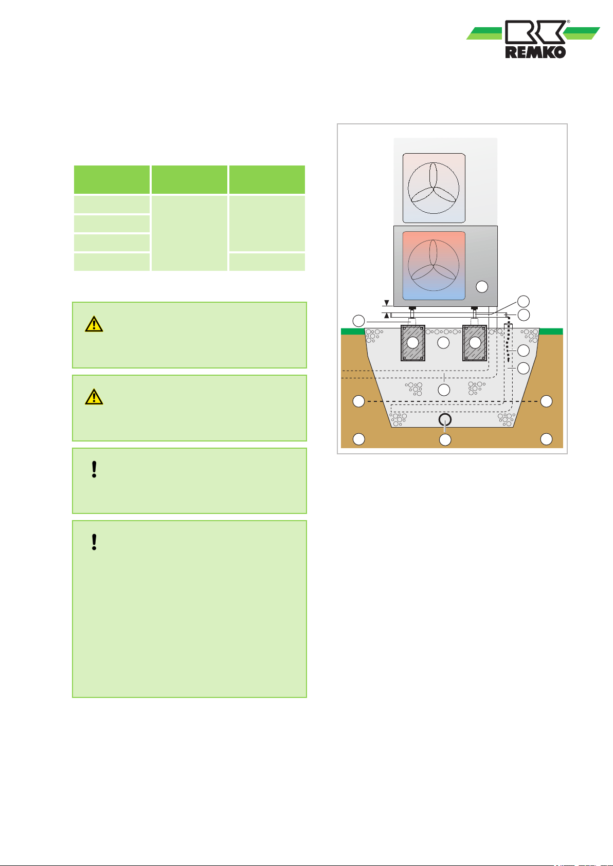
Fig. 34: Condensate drainage, seepage of condensate and strip foundation (cross-section)
1: Outdoor unit
2: Leg
3: Condensate collection tray
4: Floor bracket
NOTICE!
The escape of refrigerant contributes to climatic
change. In the event of escape, refrigerant with
a low greenhouse potential has a lesser impact
on global warming than those with a high
greenhouse potential.
This unit contains refrigerant
with a greenhouse
potential of 675. That means the escape of 1 kg
of this refrigerant has an effect on global
warming that is 675 times greater than 1 kg
CO2, based on 100 years. Do not conduct any
5: Reinforced strip foundation
HxWxD = 300x200x800mm
6: Gravel layer for seepage
7: Condensate drainage heating
8: Drainage channel
9: Conduit for refrigerant piping and electrical
connecting line (temperature-resistant up to at
least 60°C)
10: Frost line
11: Drainage pipe
12: Soil
work on the refrigerant circuit or dismantle the
unit - always enlist the help of qualified experts.
31
Page 32
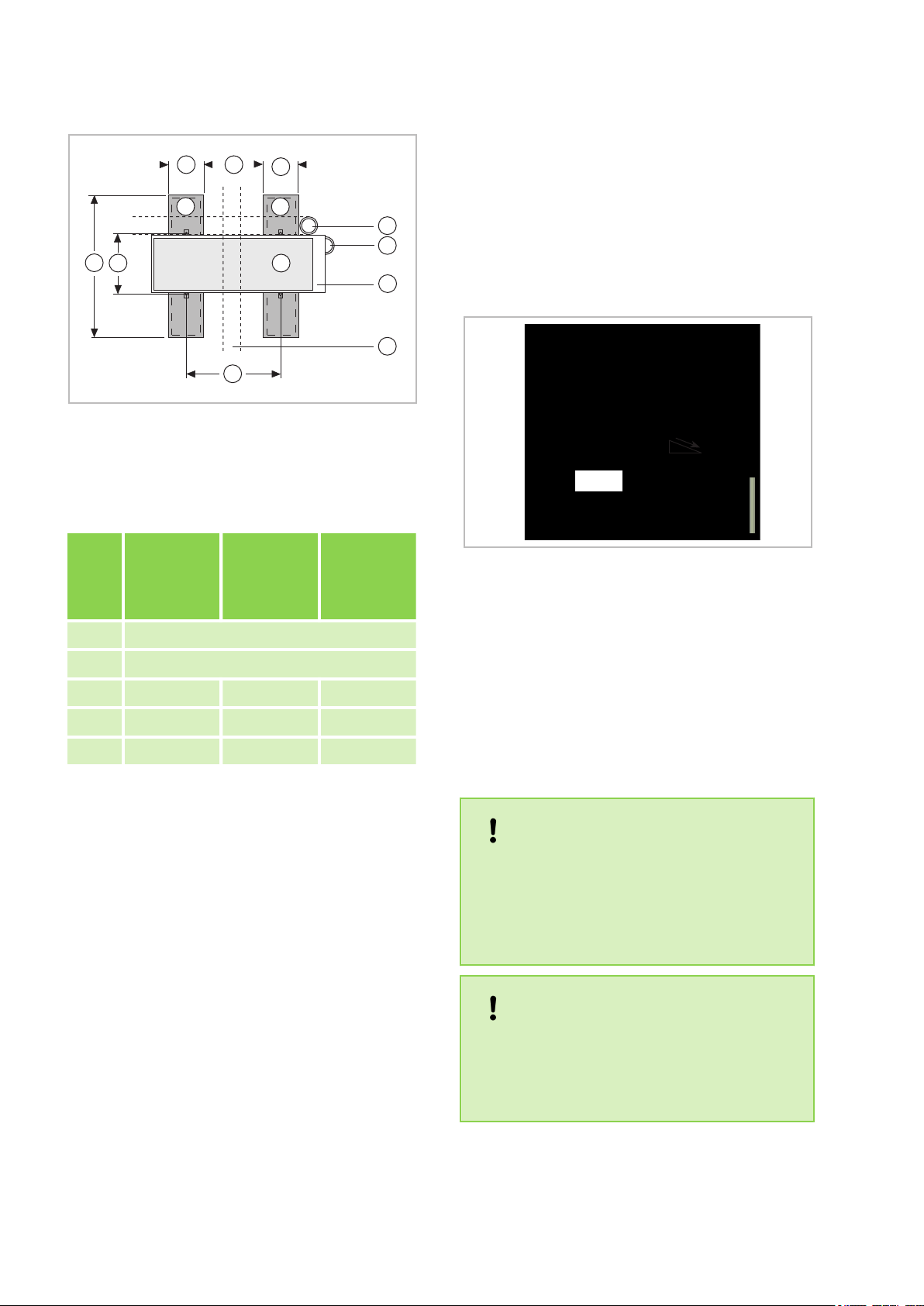
EB
B
A
D
C
11
1
5
5
8
1
9
3
min. 2%
REMKO ML series
Fig. 35: Dimensions for the strip foundation
(plan view)
For the designations of 1, 3, 5, 8, 9 and 11, please
refer to the legend for the Fig. 34
dimensioning of the strip foundation (in mm)
n When operating the unit at outside tempera-
tures below 0 °C, ensure the condensate
drainage line is laid to protect it against frost.
The lower part of the housing and condensate
tray is also to be kept frost free in order to
ensure permanent draining of the condensate.
If necessary
, fit a pipe heater.
n Following installation, check that the conden-
sate run off is unobstructed and ensure that the
line is durably leak tight.
ML 265 DC
A
Dime
nsion
T
ML 355 DC
ML 525 DCATML 685 DC
AT
A 800
B 200
C 487 514 540
D 300 333 350
E 287 314 340
Condensate drainage connection
Due to the dew point shortfall on the evaporator
condensation is created on the indoor unit in
cooling mode and on the outdoor unit in heating
mode.
Below the evaporator is a collection tray, which
must be connected to a drain.
n The condensate drainage line should have an
incline of min. 2% (
Fig. 36). This is the responsibility of the customer. If necessary, fit vapourdiffusion-proof insulation.
n Route the unit's condensate drainage line
freely into the drain line. If the condensate runs
directly into a sewer pipe, fit a trap to prevent
any unpleasant odours.
AT
unit
The condensate hose is designed to be connected
on the right and the left side (view from front).
Remove the stopper from the corresponding connection.
Safe drainage in the event of leakages
The REMKO oil separator OA 2.2 fulfils the following list of requirements from regional regulations and laws.
Fig. 36: Condensate drainage connection - Indoor
,
NOTICE!
Local regulations or environmental laws, for
example the German W
ater Resource Law
(WHG), can require suitable precautions to protect against uncontrolled draining in case of
leakage to provide for safe disposal of escaping
refrigerator oil or hazardous media.
NOTICE!
If condensate is removed via a duct in accordance with DIN EN 1717, ensure that any microbiological contamination present on the wastewater side (bacteria, fungi, viruses) cannot
enter the unit connected to it.
32
Page 33
7 Electrical wiring
2
1
4
3
1
7.1 General Information
A protected power supply cable is to be connected
to the outdoor unit and a five-core control line to
the indoor unit respectively
DANGER!
All electrical installation work is to be performed
by specialist companies. Disconnect the power
supply when connecting the electrical terminals.
WARNING!
All electric lines are in accordance VDE regulations to dimension and to lay
NOTICE!
The electrical connection of the units must be
carried out in accordance with VDE regulations.
e recommend using an FI circuit breaker that
W
is sensitive to all currents, as increased leakage
currents can occur.
.
.
Make the connection as follows:
1. Open the air inlet grill.
2. Remove the covers on the right-hand side
(Fig. 37).
3. Connect the customer-laid control line to the
terminals (
4. Re-assemble the unit.
Fig. 37).
e recommend using shielded wires for the
W
control lines.
Check all plugged and clamped terminals to
verify that they are seated correctly and make
permanent contact. T
ighten as required.
7.2 Connecting the indoor unit
e recommend that a mains/repair switch be
n W
installed near the outdoor unit.
n The terminal blocks for making the connections
are located at the rear of the unit. When the
unit is installed, measurements can be made
from the front by removing the cover.
n If an optional condensate pump is used as an
accessory in conjunction with the unit, it may
be necessary to install an additional relay with
a higher contact rating after the switch-off contact on the pump to switch off the compressor.
Fig. 37: Connecting the indoor unit
1: Cover
2: Strain relief
3: Terminal block for control line
4: Control line from outdoor unit
33
Page 34
BA
230V/1~/50 Hz
L N PE W 1(L) 2(N) S 2(N) S PE PE
2
1
W 1(L)
REMKO ML series
7.3 Connecting the outdoor unit
Proceed as follows to connect the line:
1. Remove the side-panel cover
2. Choose a cable-section according to the rele-
vant specifications.
3. Connect the lines as shown on the electrical
connection diagram.
.
7.4 Electrical wiring diagram
Connection ML 265 DC-685 DC
4. Fix the line in the strain relief and re-
assemble the unit.
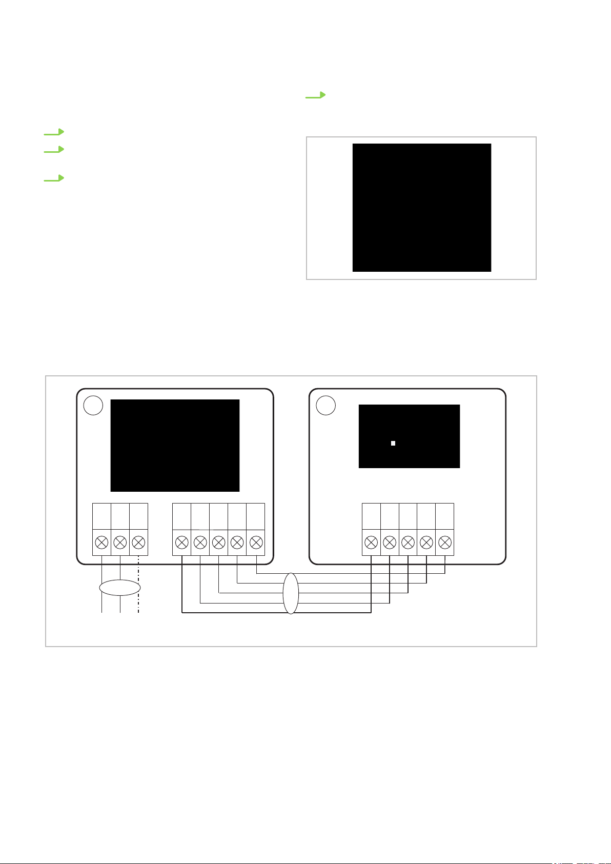
Fig. 38: Connecting the outdoor unit
Fig. 39: Electrical wiring diagram
A: Outdoor unit ML 265 DC-685 DC AT
B: Indoor unit ML 265 DC-685 DC IT
1: Power supply cable
2: Communication line
34
Page 35
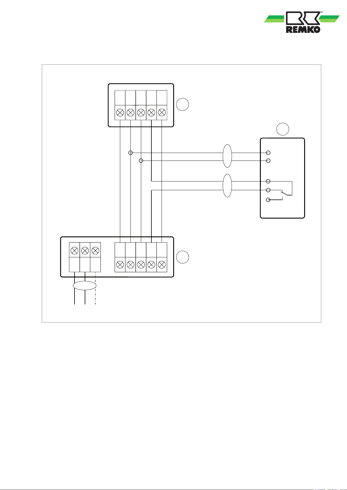
Connection of optional condensate pump KP 6/KP 8
L N PE
L N PE
L
N
WH
BK
PE
A
B
C
1
2
3
W 1(L) 2(N) S
PE
W 1(L) 2(N) S
Fig. 40: Electrical wiring diagram
A: Outdoor unit
B: Indoor unit
C: KP6/KP8 condensate pump
1: Power supply cable
2: Condensate pump supply
3: Condensate pump fault contact
BK: black
WH: white
35
Page 36
1
2
3
5
A
C
6
4
W
1(L)
2(N)
S
Yellow/
Gelb
Rot/
Red
Weiß/
White
CN 12
M
Cn15
L-OUT
L-IN
N-IN
Cn31
Blau/
Blue
CN 24
CN 33
CN 22
CN 19
CN 27
CN 18
B
REMKO ML series
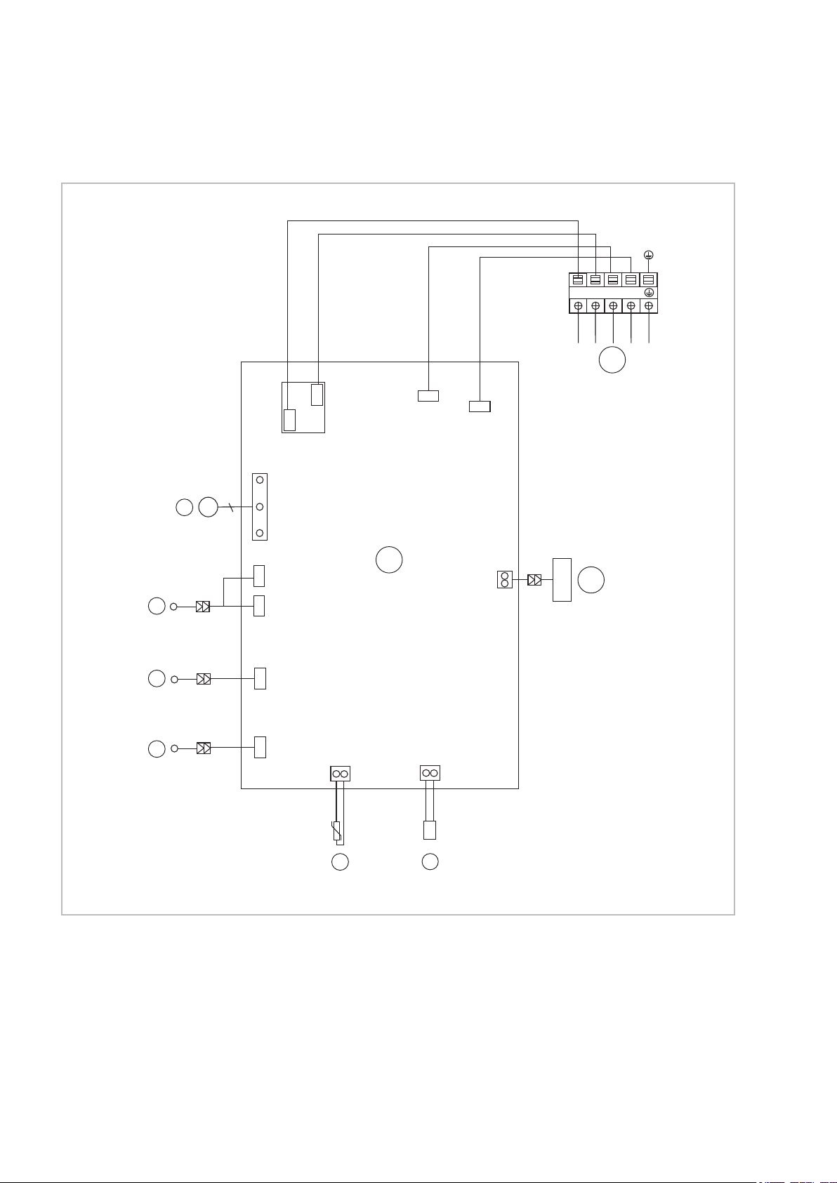
7.5 Electrical drawings
Indoor units ML 265 DC-685 DC IT
Fig. 41: Electrical drawings
A: Control board
B: Display circuit board
C: Control line from outdoor unit
1: DC fan motor
2: Engine trim + LED board
3: Fin motor, vertical
4: Fin motor, horizontal
5: Temperature probe, evaporator T2
6: Ion generator (not present)
36
Page 37
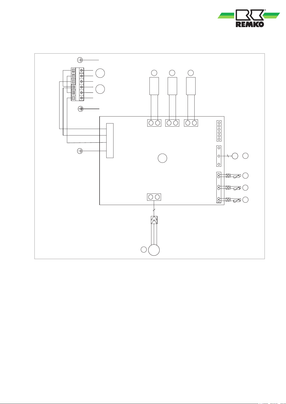
Outdoor units ML 265 DC-355 DC AT
1 2
3
5
A
B
7
6
C
8
4
W
1(L)
2(N)
S
L
N
CN 1A
CN 60
CN 17 CN 15
CN 31
CN 7
CN 21
CN 50
Blau/Blue
Rot/Red
Schwarz/Black
U
V
W
M
M
Rot/
Red
Blau/
Blue
Yellow or Black/
Gelb oder Schwarz
Braun/
Brown
Yellow and Green/
Gelb und Grün
Fig. 42: Electrical drawings
A: Control board
B: Power supply cable
C: Lines to indoor unit
1: Reversing valve
2: Crankcase heating
3: Condensate tray heating
4: Condenser/DC fan
5: Temperature probe for condenser air inlet T4
6: Temperature probe for heat gas line
7: Temperature probe for condenser outlet T3
8: Compressor
compressor T5
37
Page 38
1
2
3
5
A
B
7
6
C
8
4
W
1(L)
2(N)
S
L
N
CN 60
CN 16CN 5
Blau/Blue
Rot/Red
Schwarz/Black
U
V
W
M
Rot/
Red
Yellow/
Gelb
Rot/
Red
Yellow and Green/
Gelb und Grün
Blau/
Blue
Schwarz/
Black
CN 2
CN 7
CN 8
CN6-1
CN 414
M
W
V
U
CN 13
CN 12
Blau/Blue
CN 1
CN 10
L-OUT
RY 1
9
REMKO ML series
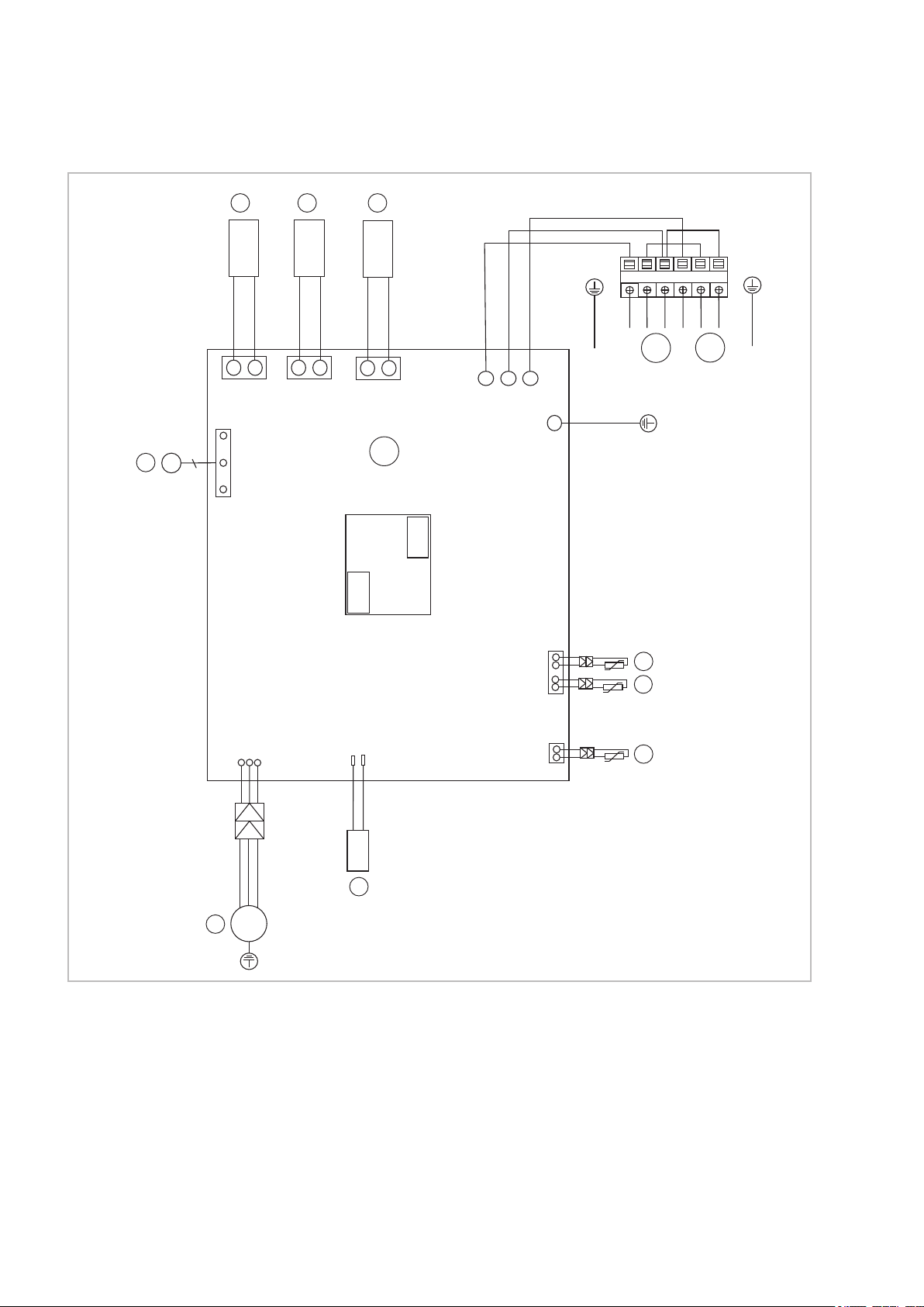
Outdoor unit ML 525 DC AT
Fig. 43: Electrical drawings
A: Control board
B: Power supply cable
C: Control line to indoor unit
1: Condensate tray heating
2: Crankcase heating
3: Reversing valve
4: Condenser/DC fan
5: Temperature probe for condenser air inlet T4
6: Temperature probe for heat gas line
compressor T5
7: Temperature probe for condenser outlet T3
8: Compressor
9: Transformer
38
Page 39
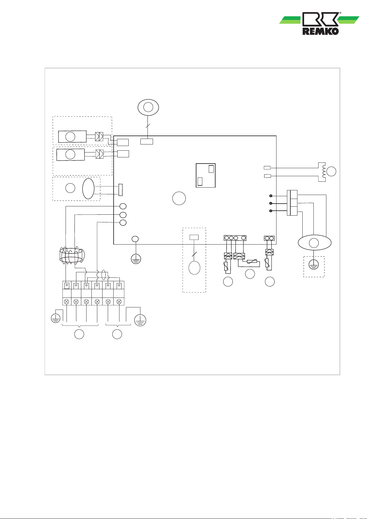
Outdoor unit ML 685 DC AT
2
1
4
3
5
6
7
8
9
10
11
A
1
2
3
Gelb
(Blau)
U
V
W
RY1
CN2
CN7
CN8
CN60
CN10
CN1
Y/G
Rot
Blau
Schwarz
Weiß
Schwarz
6
Balu
Schwarz
Rot
CN13
CN12
L-OUT
CN18
CN414
Blau
Blau
U
V
W
Y/G
CN6-1
Y/G
Rot
1(L)
2(N)
S
L N
Blau (Schwarz)
L
N
W
3
CN16
HEAT
CN5
Rot
Schwarz
Fig. 44: Electrical drawings
A: Control board
1: Supply line to the indoor unit
2: Power supply cable
3: 4-way valve (optional)
4: Crankcase heating (optional)
5: Condensate tray heating (optional)
6: Fan motor (optional)
7: Transformer
8: Compressor
9: Heat gas probe
10: Condenser temperature probe
11: Temperature probe for condenser outlet
39
Page 40
4
3
2
1
0
F
E
D
C
B
A
9
8
7
6
5
1
2
ON
X Y E
4
3
2
1
0
F
E
D
C
B
A
9
8
7
6
5
1
2
ON
CN404
CN403
X Y E
4
3
2
1
0
F
E
D
C
B
A
9
8
7
6
5
1
2
ON
4
3
2
1
0
F
E
D
C
B
A
9
8
7
6
5
1
2
ON
4
3
2
1
0
F
E
D
C
B
A
9
8
7
6
5
1
2
ON
0-15
4
3
2
1
0
F
E
D
C
B
A
9
8
7
6
5
1
2
ON
16-31
4
3
2
1
0
F
E
D
C
B
A
9
8
7
6
5
1
2
ON
32-47
4
3
2
1
0
F
E
D
C
B
A
9
8
7
6
5
1
2
ON
48-63
REMKO ML series
7.6 Connection of a superordinate controller provided by the customer
Units of type ML can be controlled by a superordinate controller
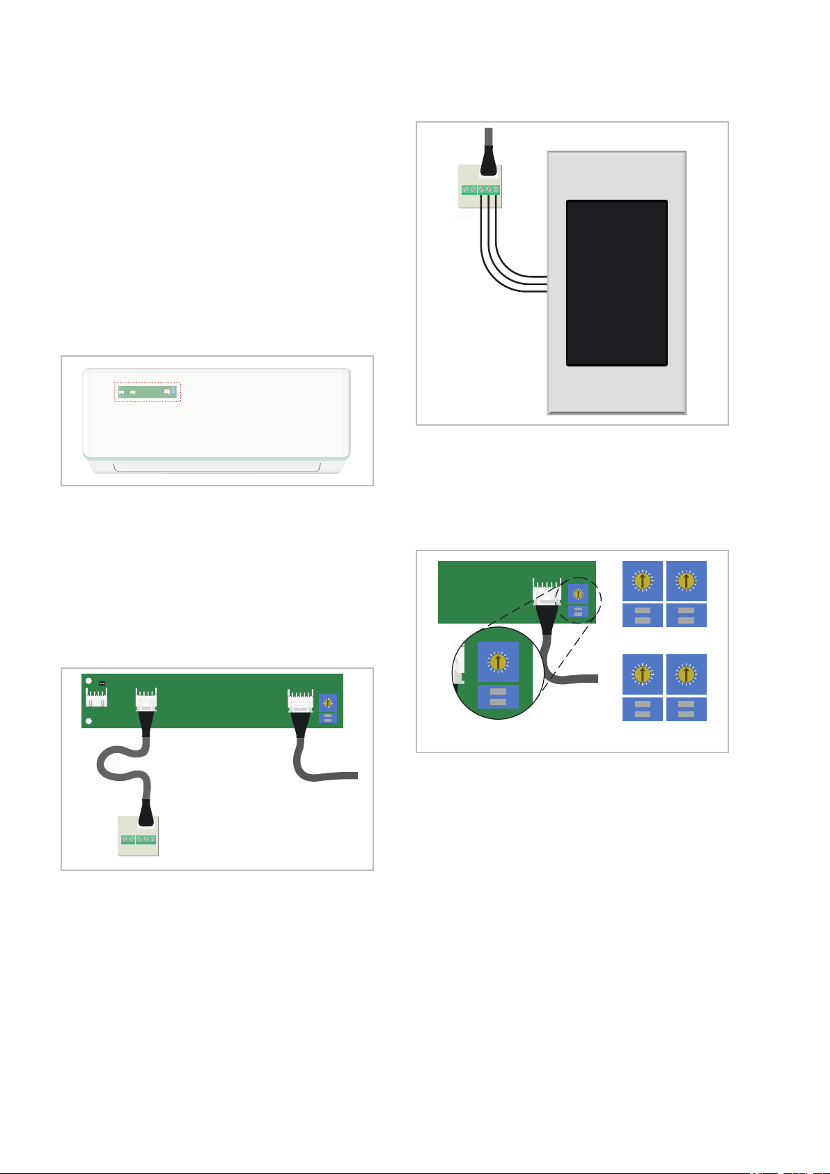
In order to realise this function, the supplied multifunction board must be inserted into the unit and
connected by plug to the adapter board (preassembled to the unit trim). Depending on the slot
(CN403 or CN404), the functions described below
are implemented. The multifunction board can be
located behind the cover of the connection terminals of the indoor unit.
.
Fig. 45: Installation position of the adapter board
Connection of a REMKO multi-central controller (MCC-1) or a REMKO Smart Control
ouch unit (SC-1):
T
Optionally, the MCC-1 Multi-Central Controller or a
Smart Control Touch unit can be connected to the
indoor unit The connection is made using the multifunction board provided on the connection terminals X, Y and E.
Fig. 46: Connect to the adapter board
The four-pin plug on the multifunction board must
be connected to the CN403 contact on the adapter
board.
Fig. 47: Connecting the controller
The controller (MCC-1 or SC-1) can then be connected to contacts X, Y and E on the multifunction
board. Further information on the connections can
be found in the operating instructions of the
respective controller
.
Fig. 48: Connection terminals
In order for the multifunction controller MCC-1 to
recognise the indoor unit, an address must be
assigned to the unit via the DIP switch of the
adapter board. Addresses 0-63 can be assigned.
The DIP switch defines the address range. The
rotary switch has 16 positions with which the specific address can be set.
ferent addresses must be assigned for the con-
Dif
nected indoor units.
40
Page 41
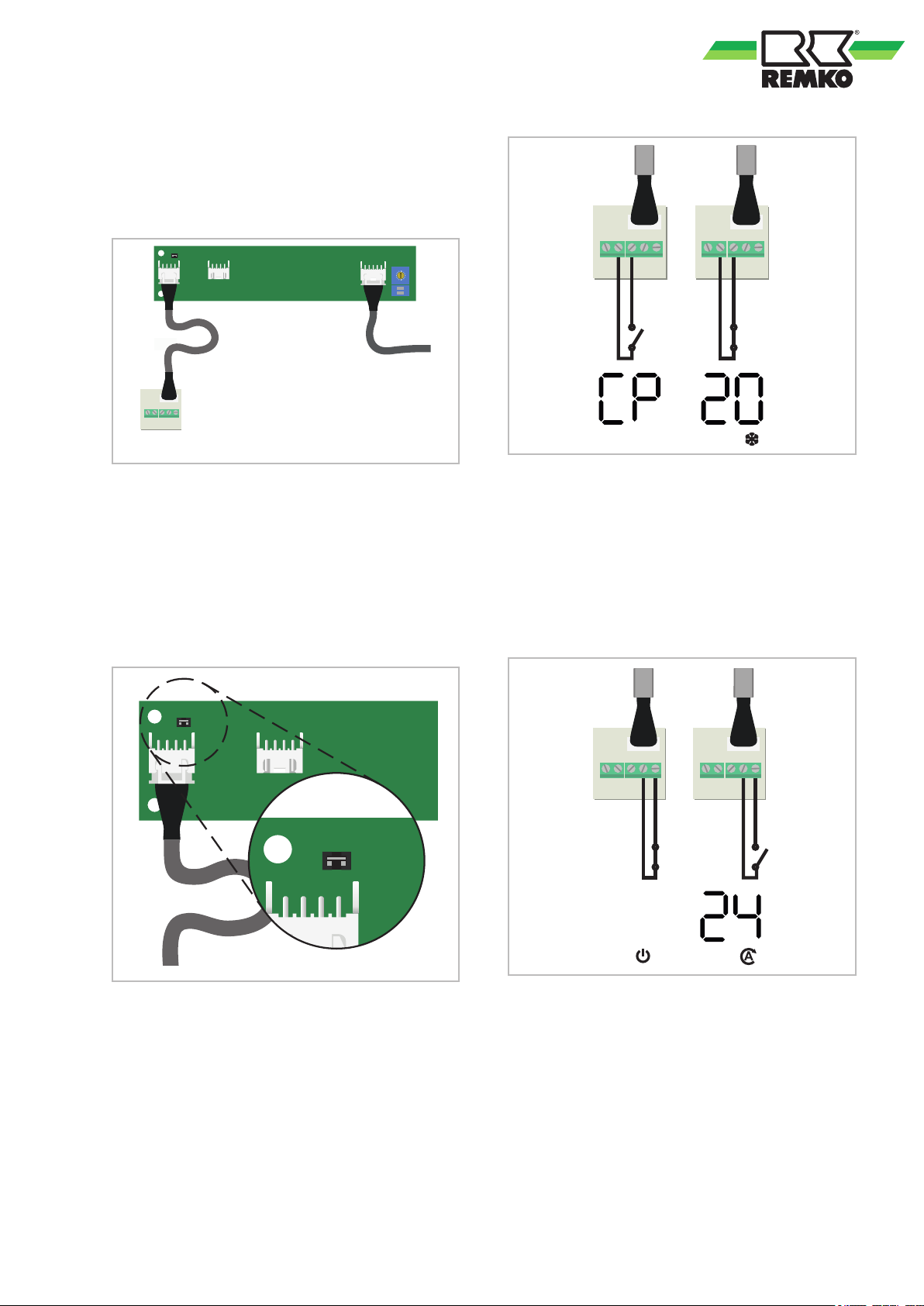
Activation and deactivation via an external ena-
4
3
2
1
0
F
E
D
C
B
A
9
8
7
6
5
1
2
ON
CN404
CN403
ON/OFF2
ON/OFF1
SWITCH2
SWITCH1
+5V
CN404
CN403
SWITCH2
SWITCH1
COOL
SWITCH2
SWITCH1
ON/OFF2
ON/OFF1
OFF
ON/OFF2
ON/OFF1
AUTO
bling contact:
Optionally
, the system can be switched by an
external controller. The connection also takes
place via the multifunction board.
Fig. 49: Connect to the adapter board
The four-pin plug on the multifunction board must
be connected to the CN404 contact on the adapter
board. The following functions are then available:
Connection terminals +5V
:
Non functional
Connection terminals SWITCH1 & SWITCH2,
external lock/enable:
Fig. 51: Connection terminal SWITCH1 &
SWITCH2
If the contact between the SWITCH1 and
SWITCH2 terminals is open, the system is in
stand-by mode and can no longer be operated by
remote control. If the contact is closed, the system
starts up again with the previous settings.
Connection terminal ON/OFF1+ON & ON/OFF2,
external activation/deactivation:
Fig. 50: Jumper
To use the SWITCH1 and SWITCH2 terminals, the
jumper above the CN404 slot must first be
removed.
Fig. 52: Connection terminal ON/OFF1 & ON/OFF2
If the contact between the terminals ON/ OFF1 and
ON/OFF2 is closed, the system is deactivated. If
the contact is opened, the system is activated
again and goes into automatic mode (setpoint
24°C). The system can be activated with the
remote control even when the contact is closed.
The system always reacts to the last input (remote
control or ON/OFF contact).
41
Page 42
REMKO ML series
8 Before commissioning
After leak testing has been successfully completed, connect the vacuum pump via the pressure
gauge station to the valve connections on the outdoor unit (see chapter "Leak testing") and create a
vacuum.
Perform the following checks prior to putting the
unit into operation for the first time and after any
work on the cooling cycle. Record the results in the
commissioning report:
n Check all refrigerant piping and valves for leak-
tightness using leak detection spray or soapy
water
.
n Check the refrigerant piping and insulation for
damage.
n Check the electrical connection between the
indoor unit and the outdoor unit for correct
polarity.
n Check that all fastenings, mountings, etc. are
firm and at the correct level.
9 Commissioning
NOTICE!
Commissioning should only be performed by
specially trained personnel and documented
after the certificate has been issued. Observe
the operating manuals for the indoor unit and
outdoor unit when commissioning the entire
system.
Once all the components have been connected
and tested, the system can be put into operation. A
functional check should be performed to verify its
correct function and identify any unusual operating
behaviour prior to handing it over to the operator
NOTICE!
Check that the shut-of
are tight after carrying out any work on the
cooling cycle. Use appropriate sealant products
as necessary.
Functional checks and test run
Check the following points:
f valves and valve caps
.
n Leak-tightness of the refrigerant piping.
n Compressor and fan running smoothly.
n In cooling mode, cold air output by the indoor
unit, and warm air output by the outdoor unit.
n Function test of the indoor unit and all program
sequences.
n Check of the surface temperature of the suc-
tion pipe and that the vaporiser is not overheating. To measure the temperature, hold the
thermometer to the suction pipe and subtract
the boiling point temperature reading on the
pressure gauge from the measured temperature.
n Record the measured temperatures in the
commissioning report.
42
Page 43
Function test of the cooling and heating modes
1. Remove the protective caps from the valves.
2. Start the commissioning procedure by briefly
opening the shut-of
unit until the pressure gauge indicates a
pressure of approx. 2 bar.
3. Check all connections for leaks with leak
detection spray and suitable leak detectors.
4. If no leaks are found, fully open the shut-of
valves by turning them anti-clockwise using a
spanner. If leaks are found, remedy the faulty
connection. It is imperative that the vacuum
creation and drying steps are repeated.
5. Activate the main circuit breaker or fuse (to
be provided by the customer).
6. Press the test knob on the outdoor unit and
wait until a frequency of min. 50 Hz is established.
7. Use the remote control to switch on the unit
and select the cooling mode, maximum fan
speed and lowest target temperature.
8. Check the overheating, outside, inside, outlet
and vaporisation temperatures and record
the measured values in the commissioning
report. Check the correct function and settings of all regulation, control and safety
devices.
9. Check the unit control system using the func-
tions described in the chapter "Operation".
T
imer, temperature setting, fan speeds and
switching to ventilation or dehumidification
mode.
10. Check the correct function of the condensate
drainage by pouring distilled water into the
condensate tray
ommended for pouring the water into the
condensation tray.
11. Switch the indoor unit to heating mode.
12. During the test run, check the functionality of
all of the previously described safety devices.
13. Record the measured values into the commissioning report and familiarise the operator
with the system.
14. Remove the pressure gauge. Check that
seals have been fitted in the sealing caps.
15. Re-install all disassembled parts.
f valves on the outdoor
f
. A bottle with a spout is rec-
43
Page 44
REMKO ML series
10 Troubleshooting, fault analysis and customer service
10.1 Troubleshooting and customer service
The unit and components are manufactured using state-of-the-art production methods and tested several
times to verify their correct function. However
in the list below. For systems with an indoor unit and outdoor unit, refer to the chapter "Troubleshooting and
customer service" in both operating manuals. Please inform your dealer if the unit is still not working correctly
after all function checks have been performed!
Operational malfunctions
Malfunction Possible causes Checks Remedial measures
, if alarms should occur, please check the functions as detailed
The unit does not start or
switches itself of
f
Power failure, undervoltage, defective mains
fuse / main switch in
OFF position
Damaged power supply Does all other elec.
Wait time after switching
on is too short
Temperature outside
operating range
Electrical surges caused
by thunderstorms
Malfunction of the
external condensate
pump
Transmission distance
too far / receiver af
by interference
fected
Does all other electrical
equipment function correctly?
equipment function correctly?
Have approx. 5 minutes
elapsed since the
restart?
Are the fans in the indoor
unit and outdoor unit
working correctly?
Have there been lightning strikes in the area
recently?
Has the pump shut down
due to a malfunction?
Does the indoor unit
beep when pressing a
key?
Check the voltage and if
necessary
come back on
Repair by specialist firm
Schedule longer wait
times
Observe temperature
ranges of indoor unit and
outdoor unit
Switch off the mains
breaker and switch it
back on. Have it
inspected by a specialist
Check and if necessary
clean the pump
Reduce the distance to
less than 6 m or change
position
, wait for it to
The unit does not
respond to the remote
control
The unit works at
reduced or no cooling
capacity
Defective remote control Is the unit running in
manual mode?
Receiver or transmitter
unit exposed to excessive solar radiation
Electromagnetic fields
are interfering with transmission
Key in remote control
jammed / two buttons
pressed at same time
Batteries in remote control are flat
Filter is dirty / air inlet /
outlet opening is blocked
by debris
Does it function correctly
in the shade?
Does it function after
removing potential
sources of interference?
Does the “Transmitting”
symbol appear on the
display?
Have new batteries been
inserted? Is the display
incomplete?
Have the filters been
cleaned?
Replace the remote control
Place the receiver and/or
transmitter unit in the
shade
Signal is not transmitted
when interference
sources are operational
Release the key / only
press one key
Insert new batteries
Clean the filters
44
Page 45
Malfunction Possible causes Checks Remedial measures
Condensate discharge
on unit
Windows and doors
open. Heating / cooling
load has increased
Cooling mode is not set Does the cooling symbol
Fins on outdoor unit
blocked by foreign
objects
Leaking cooling cycle Are there signs of frost
Drainage pipe on collection container clogged /
damaged
Faulty external condensate pump or float
Condensate has not
drained away and has
collected in the condensate drainage line
Have structural / usage
modifications been
made?
appear on the display?
Does the fan of the outdoor unit work? Are the
exchanger fins unobstructed?
on the exchanger fins of
the indoor unit?
Can the condensate
drain of
obstruction?
Is the collection tray full
of water and the pump
not running?
Is there an incline on the
condensate drainage
line? Check there is no
blockage in the pipe.
f without any
Close windows and
doors / install additional
units
Correct the settings for
the unit
Check the fan or winter
fan speed control,
reduce the air resistance
Repair by specialist
Clean the drainage pipe
and collection container
Call out a specialist to
replace the pump
Route the condensate
drainage line with an
incline and clean.
Condensate does not
drain of
NOTE
If the outdoor unit makes noises at low outside temperatures, even although it is switched off, this is not a
malfunction. This is the winding of the compressor being run briefly in order to heat up the oil within it and
also to guarantee the viscosity at low ambient temperatures. If you do not use the unit in the winter then
you can switch off the breaker
will be required!
f
. Switch it back on again at least 12 hours before the next time that the unit
Are the condensate
drainage lines unblocked
and is there a steady
incline? Are the condensate pump and liquid
level switch functioning
correctly?
Route the condensate
drainage line with an
incline and clean it. If the
liquid level switch or the
condensate pump is
defective, have them
replaced
45
Page 46
YES
REMKO ML series
Fault display on the indoor unit
Display Error description
E0 EEPROM error, indoor unit
E1 Communication error between indoor unit and outdoor unit
E3 Fan speed control indoor unit disabled
E4 Room temperature probe T1 defective
E5 Temperature probe, evaporator T2 defective
F0 Overflow protection
F1 Temperature probe air inlet outdoor unit T4 defective
F2 Temperature probe, evaporator outlet T3 defective
F3 Temperature probe, heat gas line T5 defective
F4 EEPROM error, outdoor unit
F5 Condenser fan speed control probe not working
P0 Compressor actuation error
P1 Over-voltage or under-voltage error
P2 Compressor overheating protection (heat gas temperature too high)
P4 Inverter control disabled
EC No cooling capacity after 30 minutes
CP No external enable
-- Mode conflict
Für die Fehlerbehebung siehe Troubleshooting auf den nachfolgenden Seiten.
10.2 Indoor unit fault analysis
Error code: E0/F4
Reason: The control board of the outdoor unit or indoor unit cannot read the unit memory
(EEPROM)
Cause:
n Installation error
n Control boards of outdoor unit or indoor unit defective
Switch off voltage, switch on again 2 minutes
later. Is the error still present?
Replace the circuit boards of the outdoor unit
and indoor unit in turn, in order to locate the
defective EEPROM
46
Page 47
Error code: E1
YES
NO
YES YES
YES
NO
NO
YES
NO
Reason: The indoor unit does not receive a signal from the outdoor unit within 110 seconds. The
check is performed 4 times in a row
, then error E1 is displayed.
Cause:
Switch off voltage, switch on again 2 minutes
later
Measure the voltage between the “S” and “N”
terminals of the outdoor unit. Does the valve
fluctuate between -25 V and 25 V?
Check electrical connections in the outdoor
n Electrical connection not configured correctly
n Control boards outdoor unit or indoor unit defective
. Is the error still present?
unit. Are they OK?
Is the transformer OK?
Check electrical connections in the indoor unit.
Are they OK?
Replace the control boards of the indoor unit. Is
the error rectified?
Replace the control boards of the outdoor unit
Replace the transformer
Replace the control boards of the outdoor unit.
Is the error rectified?
Replace the control boards of the indoor unit
Fig. 53: Transformer measurement
Check the transformer (must not be connected to a
condenser) with a multimeter
approx. 0 Ohm. If the value deviates, replace the
transformer.
. The normal value is
47
Page 48
NO
YES
NO
YES
NO
YES
NO
YES
NO
REMKO ML series
Error code: E3/F5
Reason: If the fan speed of the indoor unit/outdoor unit falls below 300 rpm, the unit switches off
and the display shows error code E3 or F5
Cause:
Switch off voltage, switch on again 2
minutes later
De-energise the unit and attempt to
turn the fan wheel by hand. Does it
Check the electrical connections.
Are these correctly implemented?
Measure the voltage at the corre-
sponding connector plug on the con-
trol board (see section
dure’ on page 49). Does the
measured voltage lie within the toler-
n Electrical connection faulty
n Evaporator fan wheel defective
n Evaporator fan motor defective
n Control board faulty
. Is the error still
present?
rotate freely?
Ä
‘Proce-
ance range?
The unit operates normally.
Check the motor and the fan
wheel bearing, and replace the
defective parts.
Correctly establish the electrical
connection
Replace the control board.
Replace the fan motor. Is the error
rectified?
48
Page 49
Procedure
1 3 4 5 6
DC fan motor of the indoor unit (control chip is installed in the motor):
Switch on the voltage to the unit. In standby mode, measure the unit between terminals 1-3 and 4-3 of the
connector plug. Check the measured values against those listed in the table below
problem with the control board and it must be replaced.
. If these differ, there is a
Fig. 54: Motor measurements
Terminal Colour Voltage
1 Red 280V~380V
2 --- ---
3 Black 0 V
4 White 14-17.5V
5 Yellow 0~5.6V
6 Blue 14-17.5V
DC fan motor of the outdoor unit (control chip is installed in the motor):
Measure the resistance between terminals 1-3 and 4-3. This should be roughly identical. If the resistance
deviates significantly, assume that the motor is defective and must be replaced.
49
Page 50
YES
YES
NO YES
YES
NO
REMKO ML series
Error code: EC
Reason: The evaporator probe T2 measures the actual value with the compressor start and takes
this as the reference value T
has not dropped by 2 °C for at least 4 seconds then the system assumes that the refrig-
erant is low
error code "EC".
. The measurement is performed a total of 3 times before the display shows the
. If, 5 minutes after the compressor start, the value T
Start
Start
Cause:
Switch off voltage, switch on again 2 minutes
Check whether the indoor unit blows out cold
Check the cooling circuit for leaks. Did you find
Check the cooling circuit for any blockages. Are
the shut-of
n Refrigerant low or cooling circuit blocked
n Evaporator probe T2 defective
n Indoor unit control board defective
later. Is the error still present?
.
air
a leak?
f valves on the outdoor unit open?
Check the position and function of the evapo-
rator probe T2. Is it correctly seated and with
the correct resistance?
Exchange the control boards of the indoor unit.
Remedy leaks and put the unit back into opera-
tion.
50
Page 51
Error code: E4 / E5 / F1 / F2 / F3
NO
YES
NO
YES
Reason: If the test voltage of the probes is lower than 0.06 V or higher than 4.94 V then the display
shows the error code of the corresponding probe.
Cause:
Check the connecting cable between the con-
trol board and the temperature probe. Is it OK
Check the probe for correct resistance,
depending on the temperature (see resistance
Replace the corresponding control board.
n Electrical connection faulty
n T
emperature probe defective
n Control board defective
and correctly connected?
table)
Establish a proper connection.
Replace the probe.
Fig. 55: Check the probes
51
Page 52
NO
YES
NO
YES
NO
YES
NO
YES
NO
YES
REMKO ML series
Error code: F0
Reason: Safety shutdown due to overly high current consumption of individual unit components
Cause:
Check the supply voltage. Is this correct?
Check the cooling circuit for any blockages. Is
Check the winding resistances of the com-
Check the electrical connections. Are these cor-
n Faulty power supply
n Cooling circuit blocked
n Faulty control board
n Electrical connections faulty
n Compressor defective
the cooling circuit OK?
pressor
. Are they OK?
rectly implemented?
Switch the unit off and ensure correct supply
voltage.
Remove the blockage (shut-off valve open?)
Replace the compressor.
Replace or correct the electrical connections.
Does the transformer operate fault-free? (See
Ä
on page 47)
Replace the outdoor unit.
Replace the transformer or control boards of
the outdoor unit.
52
Page 53
Error code: P0
YES
NO
NO
YES
NO
YES
NO
YES
Reason: If the power supply to the compressor controller is faulty, the display shows the error code
“P0” and the unit switches of
f
Cause:
Check the connecting cables between the con-
trol board and compressor? Are they faulty?
Check the inverter controller (see section
Ä
‘Check the inverter controller’ on page 53).
Check the condenser fan motor. Is it working
Check the winding resistances of the com-
n Electrical connection faulty
n Faulty control board
n Condenser fan motor defective or blocked
n Compressor defective
Error rectified?
correctly?
pressor
. Are they OK?
Establish a correct connection between the
control board and compressor
Replace the control board.
See troubleshooting fault F5
Replace the compressor.
.
Exchange the control boards of the outdoor
unit.
Check the inverter controller
Switch off the power supply to the unit. Wait until the capacitors are fully discharged and disconnect the compressor from the control board.
Check the resistances at the outputs of the control board with the aid of a digital voltmeter as follows:
ML 265 DC ML 355 DC ML 525 DC ML 685 DC
blue - red
blue - black
1.57 W
(20°C/68°F)
red - blue
1.82 W
(20°C/68°F)
1.72 W
(20°C/68°F)
0.75 W
(20°C/68°F)
53
Page 54
NO
YES
NO
YES
NO
YES
NO
YES
REMKO ML series
Error code: P1
Reason: Overvoltage or undervoltage protection has tripped
Cause:
Check the power supply. Is the supply voltage
Check the electrical connections. Are they OK?
Switch the power on and put the unit into
standby mode. Measure the voltage on the
board, at contacts "P" and "N". This should be
approx. 310V
unit. The voltage between "P" and "N" should
now be between 220-400V. Is the correct
Check the transformer. Is a defect present?
n Faulty supply voltage
n Refrigerant low or cooling circuit blocked
n Faulty control board
correct?
, 340V or 380V DC. Now start the
voltage applied?
Switch the unit off and have the power supply
checked/corrected.
Replace the electrical connections.
Replace the control board.
Replace the control board.
Replace the transformer.
54
Page 55
Error code: P2 (with units with a thermal contact)
YES
NO
YES
NO
YES
NO
YES
YES
NO
YES
Reason: If the test voltage of the thermal contact does not lie at 5 V, then the display shows the
error message “P2”
Cause:
Check the air flow
volumes of the
indoor unit and out-
door unit. Are they
blocked or dirty?
Switch off the power
supply to the unit
and switch it on
again after 10 mins.
Does the unit start
up?
Check the tempera-
ture of the com-
pressor
heated up?
n Faulty supply voltage
n Refrigerant low or cooling circuit blocked
n Faulty control board
. Has it
Clean the filter or heat exchanger and ensure a sufficient air flow volume.
Check the thermal contact. Is it correctly connected?
Measure the resistance of the thermal contact.
Is it 0?
Connect it correctly.
Check the cooling
circuit. Is this OK?
Replace the thermal
contact.
Replace the control board of the outdoor unit.
55
Page 56
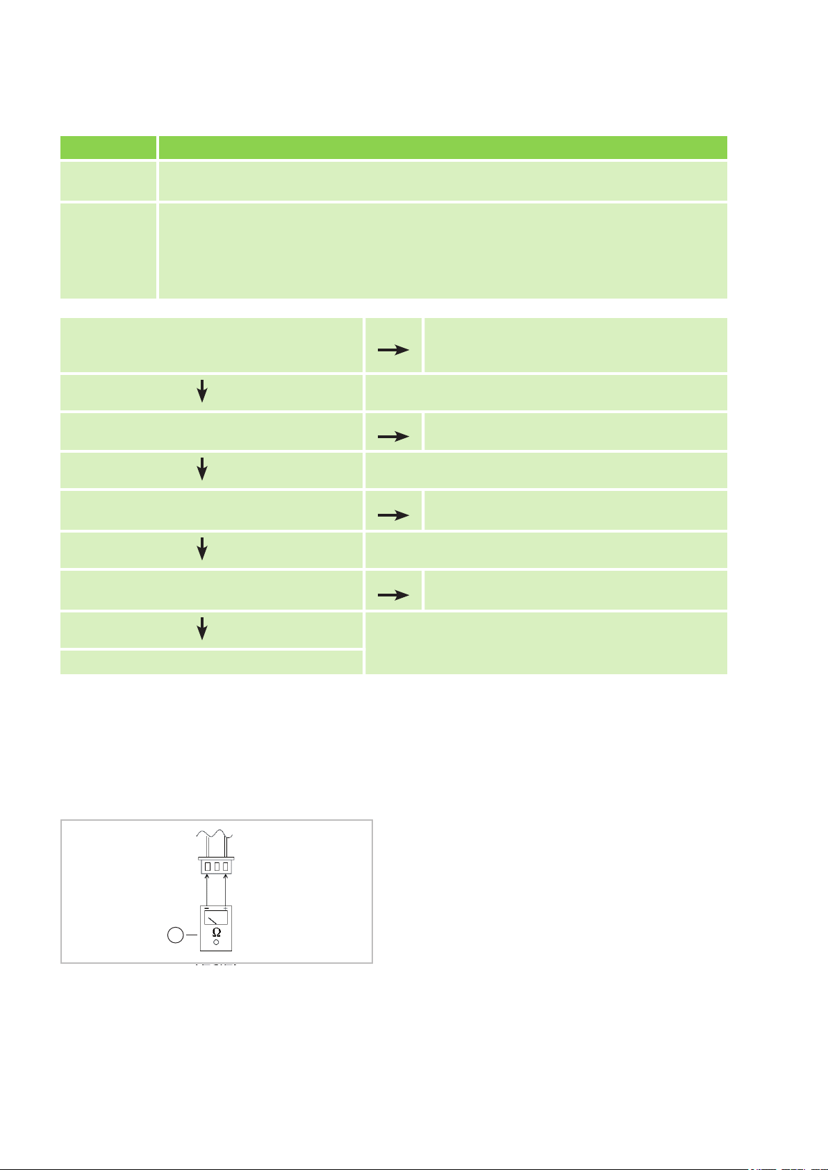
YES
NO
NO
YES
NO
YES
NO
YES
1
REMKO ML series
Error code: P4
Reason: Safety shutdown of inverter controller. Internal system monitoring triggered (e.g. communi-
cation problem between board and compressor
, the compressor speed is not OK)
Cause:
Check the electrical connection between the
control board and compressor
Check the inverter controller. Is this functional?
Check the condenser fan motor. Is this OK?
Check the winding resistances of the com-
n Faulty electrical connections
n Inverter regulation on board defective
n Condenser fan motor defective
n Compressor defective
n Control board defective
. Are these cor-
rectly implemented?
pressor
. Are they OK?
Establish a proper connection.
Replace the control board.
Follow the instructions for troubleshooting fault
F5
Replace the compressor
Replace the control boards of the outdoor unit.
Check the individual components
Check the temperature probes
Disconnect the temperature probe from the control
board and measure the resistance on the plug's
contacts.
Fig. 56: Check temperature probes
1: Multimeter
56
Page 57
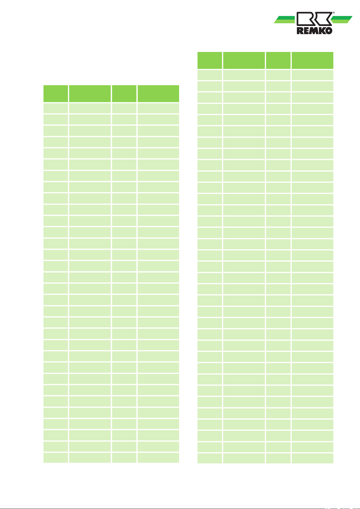
10.3 Resistances of the
temperature probes
Probe T1, T2, T3 and T4
Temp.
(°C)
-20 115.27 12 18.72
-19 108.15 13 17.80
-18 101.52 14 16.93
-17 96.34 15 16.12
-16 89.59 16 15.34
-15 84.22 17 14.62
-14 79.31 18 13.92
-13 74.54 19 13.26
-12 70.17 20 12.64
-11 66.09 21 12.06
-10 62.28 22 11.50
Resistance
(kW)
Temp.
(°C)
Resistance
(kW)
Temp.
(°C)
44 4.39 79 1.21
45 4.21 80 1.17
46 4.05 81 1.14
47 3.89 82 1.10
48 3.73 83 1.06
49 3.59 84 1.03
50 3.45 85 1.00
51 3.32 86 0.97
52 3.19 87 0.94
53 3.07 88 0.91
54 2.96 89 0.88
55 2.84 90 0.85
56 2.74 91 0.83
57 2.64 92 0.80
Resistance
(kW)
Temp.
(°C)
Resistance
(kW)
-9 58.71 23 10.97
-8 56.37 24 10.47
-7 52.24 25 10.00
-6 49.32 26 9.55
-5 46.57 27 9.12
-4 44.00 28 8.72
-3 41.59 29 8.34
-2 39.82 30 7.97
-1 37.20 31 7.62
0 35.20 32 7.29
1 33.33 33 6.98
2 31.56 34 6.68
3 29.91 35 6.40
4 28.35 36 6.13
5 26.88 37 5.87
6 25.50 38 5.63
58 2.54 93 0.78
59 2.45 94 0.75
60 2.36 95 0.73
61 2.27 96 0.71
62 2.19 97 0.69
63 2.11 98 0.67
64 2.04 99 0.65
65 1.97 100 0.63
66 1.90 101 0.61
67 1.83 102 0.59
68 1.77 103 0.58
69 1.71 104 0.56
70 1.65 105 0.54
71 1.59 106 0.53
72 1.54 107 0.51
73 1.48 108 0.50
7 24.19 39 5.40
8 22.57 40 5.18
9 21.81 41 4.96
10 20.72 42 4.76
11 19.69 43 4.57
57
74 1.43 109 0.48
75 1.39 110 0.47
76 1.34 111 0.46
77 1.29 112 0.45
78 1.25 113 0.43
Page 58
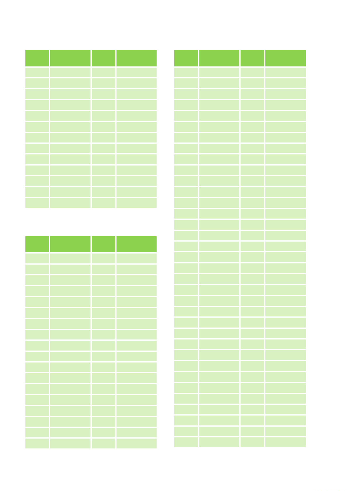
REMKO ML series
Temp.
(°C)
114 0.42 127 0.30
115 0.41 128 0.29
116 0.40 129 0.28
117 0.39 130 0.28
118 0.38 131 0.27
119 0.37 132 0.26
120 0.36 133 0.26
121 0.35 134 0.25
122 0.34 135 0.25
123 0.33 136 0.24
124 0.32 137 0.23
125 0.32 138 0.23
126 0.31 139 0.22
Resistance
(kW)
Temp.
(°C)
Resistance
(kW)
Temp.
(°C)
16 82.54 51 18.96
17 78.79 52 18.26
18 75.24 53 17.58
19 71.86 54 16.94
20 68.66 55 16.32
21 65.62 56 15.73
22 62.73 57 15.16
23 59.98 58 14.62
24 57.37 59 14.09
25 54.89 60 13.59
26 52.53 61 13.11
27 50.28 62 12.65
28 48.14 63 12.21
29 46.11 64 11.79
Resistance
(kW)
Temp.
(°C)
Resistance
(kW)
Probe T5
Temp.
(°C)
-20 542.7 -2 200.7
-19 511.9 -1 190.5
-18 483.0 0 180.9
-17 455.9 1 171.9
-16 430.5 2 163.3
-15 406.7 3 155.2
-14 384.3 4 147.6
-13 363.3 5 140.4
-12 343.6 6 133.5
-11 325.1 7 127.1
-10 307.7 8 121.0
-9 291.3 9 115.2
-8 275.9 10 109.8
-7 261.4 11 104.6
-6 247.8 12 99.69
-5 234.9 13 95.05
-4 222.8 14 90.66
-3 211.4 15 86.49
Resistance
(kW)
Temp.
(°C)
Resistance
(kW)
30 44.17 65 11.38
31 42.33 66 10.99
32 40.57 67 10.61
33 38.89 68 10.25
34 37.30 69 9.90
35 35.78 70 9.57
36 34.32 71 9.25
37 32.94 72 8.94
38 31.62 73 8.64
39 30.36 74 8.36
40 29.15 75 8.08
41 28.00 76 7.82
42 26.90 77 7.57
43 25.86 78 7.32
44 24.85 79 7.09
45 23.89 80 6.86
46 22.89 81 6.64
47 22.10 82 6.43
48 21.26 83 6.23
49 20.46 84 6.03
50 19.69 85 5.84
58
Page 59
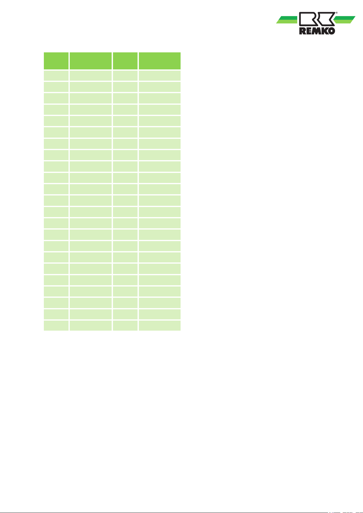
Temp.
(°C)
86 5.66 109 2.86
87 5.49 110 2.78
88 5.32 111 2.70
89 5.16 112 2.63
90 5.00 113 2.56
91 4.85 114 2.49
92 4.70 115 2.42
93 4.56 116 2.36
94 4.43 117 2.29
95 4.29 118 2.23
96 4.17 119 2.17
97 4.05 120 2.12
98 3.93 121 2.06
99 3.81 122 2.01
Resistance
(kW)
Temp.
(°C)
Resistance
(kW)
100 3.70 123 1.96
101 3.60 124 1.91
102 3.49 125 1.86
103 3.39 126 1.81
104 3.30 127 1.76
105 3.20 128 1.72
106 3.11 129 1.67
107 3.03 130 1.63
108 2.94
59
Page 60
REMKO ML series
11 Care and maintenance
Regular care and observation of some basic points
will ensure trouble-free operation and a long
service life.
DANGER!
Prior to performing any work, ensure the equipment is disconnected from the voltage supply
and secured to prevent accidental switch-on!
Care
n Ensure the unit is protected against dirt, mould
and other deposits.
n Only clean the unit using a damp cloth. Do not
use any caustic, abrasive or solvent-based
cleaning products. Do not use a jet of water.
n Clean the fins on the unit prior to long shut-
down periods.
Maintenance
n It is recommended that you take out a mainte-
nance contract with an annual service from an
appropriate specialist firm.
This enables you to ensure the operational reliability of the plant at all times!
NOTICE!
Statutory regulations require an annual leak test
for the cooling cycle dependant on the refrigerant quantity. Inspection and documentation of
the work performed is to be carried out by specialist technicians.
Type of task
Checks/maintenance/inspection
General
Check voltage and current
Check function of compressor/fans
Dirt on condenser/evaporator
Check refrigerant fill quantity
Check condensate drainage
Check insulation
Check moving parts
Sealing test for cooling cycle
1)
See note
Commis-
sioning
l
l
l
l l
l
l
l
l
l
Monthly
Every 6
months
l
l
Yearly
l
l
l
l
l
1)
l
60
Page 61
Cleaning the housing
1. Disconnect the power supply to the unit.
2. Open and fold the air inlet grill on the front
side upwards.
3. Clean the grill and cover with a soft, damp
cloth.
4. Switch the power supply back on.
Air filter for indoor unit
Clean the air filter at intervals of no more than 2
weeks. Reduce this interval if the air is especially
dirty
.
Cleaning the filter
1. Disconnect the power supply to the unit.
2. Open the front side of the unit by folding the
grill upwards and allowing it to engage
(Fig. 57).
3. Raise the filter and pull it out in a downwards
direction (
4. Clean the filter with a commercially available
vacuum cleaner (
dirty side so it is facing upwards.
5. Dirt can also be removed by carefully
cleaning with lukewarm water and mild
cleaning agents (
should be face down.
6. If water is used, let the filter dry out properly
in the air before fitting it back into the unit.
Fig. 57).
Fig. 58). To do so, turn the
Fig. 59). The dirty side
Fig. 57: Folding the grill upwards
Fig. 58: Cleaning with a vacuum cleaner
7. Carefully insert the filter
locates correctly.
8. Close the front side as described above in
reverse order
9. Switch the power supply back on.
10. Switch the unit back on.
Cleaning the condensate pump (accessories)
The indoor unit may contain an optional integrated
or separate condensate pump, which pumps out
any accumulated condensate into higher positioned drains.
Observe the care and maintenance instructions in
the separate operating manual.
.
. Ensure that it
Fig. 59: Cleaning with lukewarm water
61
Page 62

REMKO ML series
12 Shutdown
Temporary shutdown
1. Let the indoor unit run for 2 to 3 hours in
recirculation mode, or in cooling mode at
maximum temperature, to extract any
residual humidity from the unit.
2. Shut down the system using the remote control.
3. Switch of
unit.
4. Cover the unit as far as possible with plastic
foil in order to protect it from the influences of
weather
Permanent shutdown
Ensure that units and components are disposed of
in accordance with local regulations, e.g. through
authorised disposal and recycling specialists or at
collection points.
REMKO GmbH & Co. KG or your contractual
partner will be pleased to provide a list of certified
firms in your area.
f the electrical power supply to the
.
62
Page 63
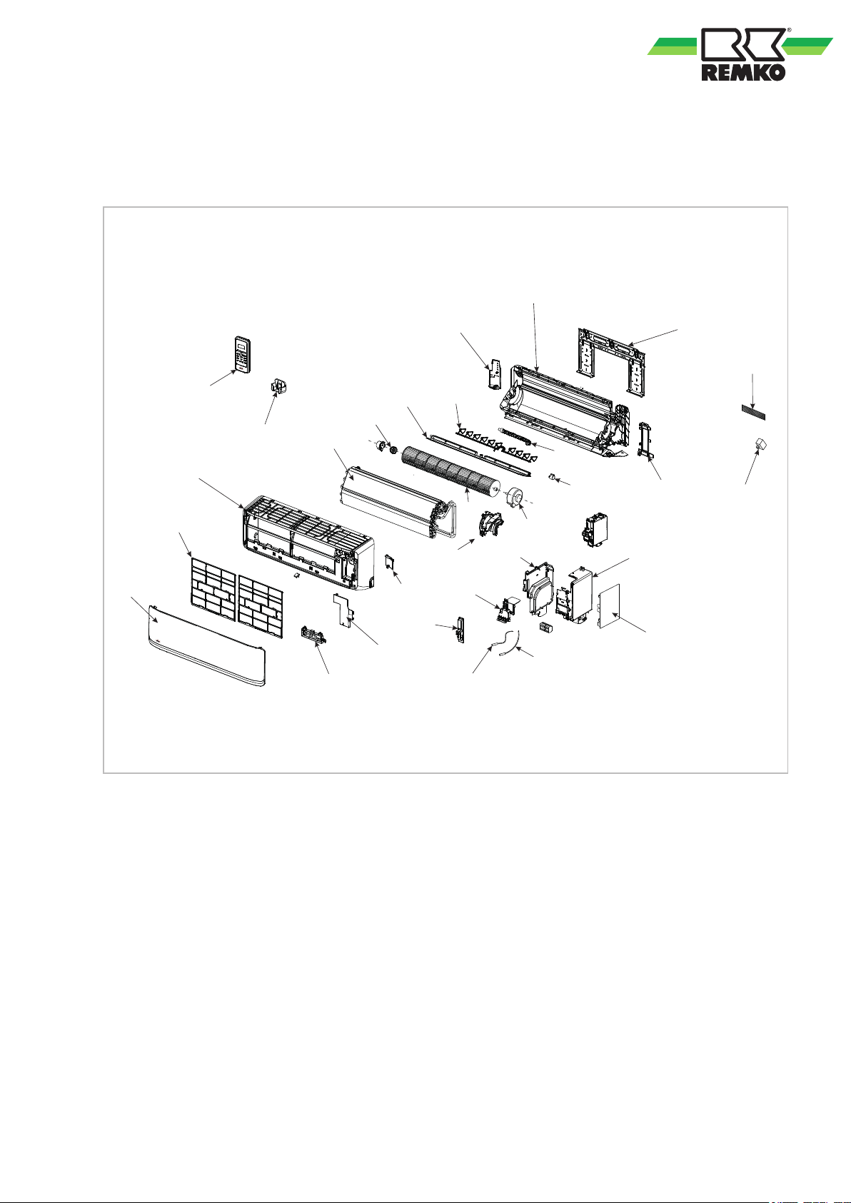
13 Exploded view and spare parts lists
11
6
4
9
10
13
12
1
3
7
8
5
2
14
15
16
17
18
19
20
21
22
23
24
25
26
27
28
29
30
13.1 Exploded view - Indoor unit
Fig. 60: Exploded view of the unit ML 265 DC-685 DC IT
We reserve the right to modify the dimensions and design as part of the ongoing technical development
process.
63
Page 64
REMKO ML series
13.2 Spare parts list - Indoor unit
IMPOR
To ensure the correct delivery of spare parts, please always the device type with the corresponding serial
number (see type plate)
No. Designation
1 Unit trim
2 Air filter, single
3 Circuit board, display
4 Fin motor
5 Air outlet flap, horizontal
6 Housing back incl. condensate tray
7 Evaporator
8 Fan wheel
9 Fan motor
10 Control board
11 IR remote control
12 Room temperature probe T1
TANT!
13 Temperature probe, evaporator T2
14 Housing front
15 Plastic covering, terminal block
16 Plastic covering, board
17 Housing part, electronics module
18 Housing part, electronics module
19 Plastic holder, fan motor
20 Housing cover, electronics module
21 Housing part, housing back right
22 Ion generator
23 Fine dust filter
24 Wall bracket
25 Air outlet fins, vertical
26 Bearing, fan wheel
27 IR remote control holder
28 Housing back, electronics module
29 Housing part, housing back left
30 Condensate hose
64
Page 65
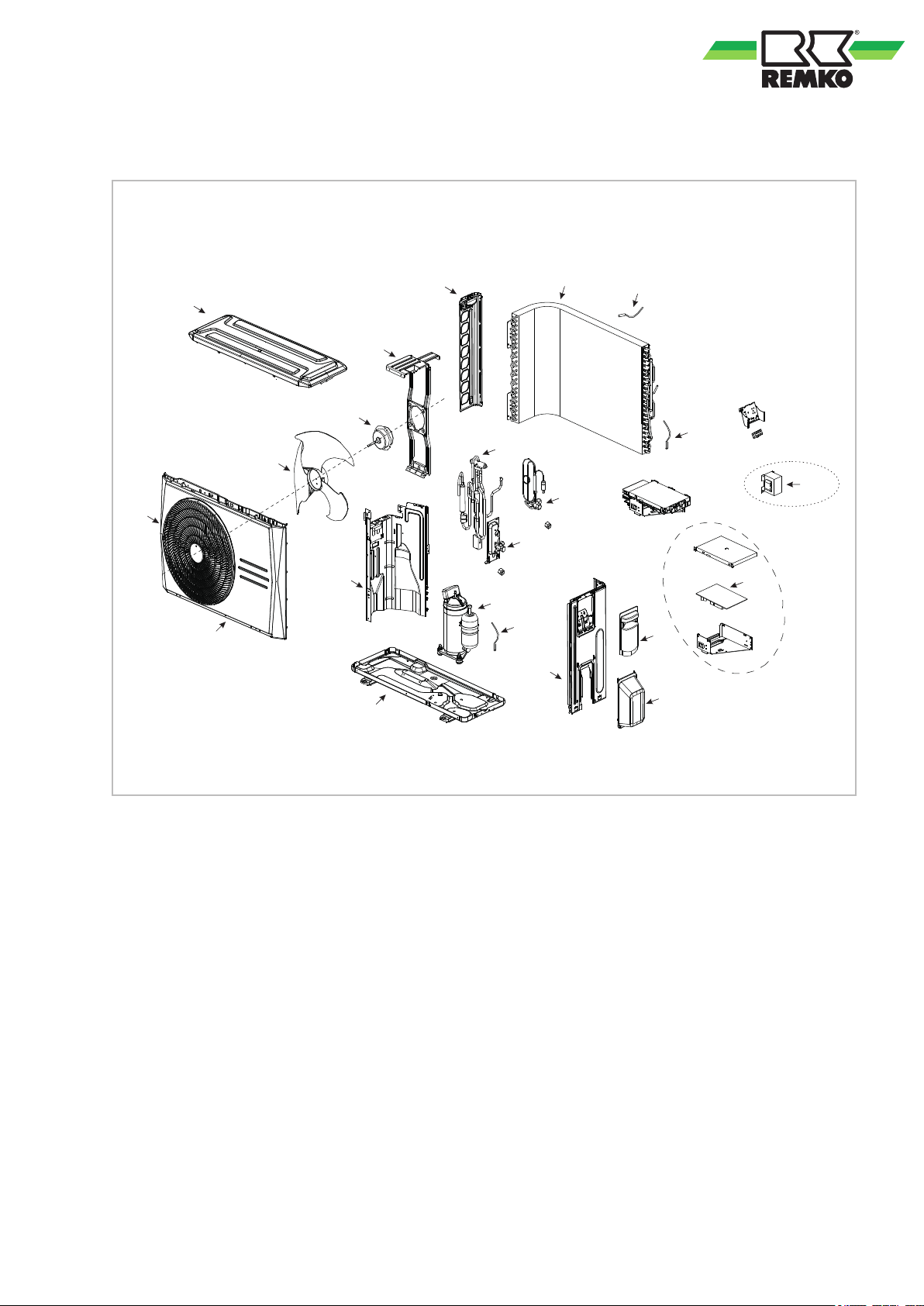
13.3 Exploded view of the outdoor unit
1
2
3
4
5
6
7
8
9
10
11
12
13
14
17
18
16
21
19
15
20
22
Fig. 61: Exploded view of the outdoor units ML 265 DC-685 DC AT
We reserve the right to modify the dimensions and design as part of the ongoing technical development
process.
65
Page 66
REMKO ML series
13.4 Spare parts list - Outdoor unit
IMPOR
To ensure the correct delivery of spare parts, please always the device type with the corresponding serial
number (see type plate)
No. Designation
1 Front panel, left
2 Protection grid, front plate
3 Fan blade
4 Fan motor
5 Fan motor bracket
6 Corner panel
7 Housing cover
8 Base plate
9 Partitioning panel
10 Air probe condenser
11 Condenser
12 Condenser pipe placement probe
TANT!
13 Inductor
14 Control board
15 Shut-off valve, injection pipe
16 Side section, housing, right
17 Plastic covering, terminal block
18 Plastic covering, pipe connections
19 Shut-off valve, suction pipe
20 4-way valve
21 Compressor pipe placement probe
22 Compressor
23 Crankcase heating
24 Condensate tray heating
66
Page 67
14 Index
A
Alarms
Checks .............................44
Possible causes ...................... 44
Remedial measures ................... 44
Assembly
Strip foundation ...................... 31
C
Care and maintenance ................... 60
Cleaning
Air filter for indoor unit ................. 61
Condensate pump ....................61
Housing ............................ 61
Condensate drainage connection and safe
drainage .............................. 31
Condensate pump, electrical wiring diagram ... 35
Customer service ....................... 44
D
Disposal of equipment .....................8
E
Electrical drawings ..............36, 37, 38, 39
Electrical wiring ......................... 33
Electrical wiring diagram .................. 34
Electrical wiring diagram, condensate pump ... 35
Environmental protection ...................8
Exploded view of the unit .............. 63, 65
F
Fault display on the indoor unit ............. 46
Function test of the cooling and heating modes
Functional checks ....................... 42
43
Multifunction board, connection .............40
O
Oil return measures ......................27
Ordering spare parts .................. 64, 66
P
Propellant in accordance with Kyoto Protocol .. 1
R
Remote control
Keys ...............................15
Resistances
Temperature probes ................... 57
S
Safe drainage in the event of leakages ....... 32
Safety
Dangers of failure to observe the safety
notes ............................... 5
General ............................. 5
Identification of notes ................... 5
Instructions for the operator .............. 6
Note for inspection work .................6
Note for installation work ................ 6
Note for maintenance work .............. 6
Personnel qualifications ................. 5
Safety-conscious working ................6
Unauthorised modification ...............7
Unauthorised replacement part manufacture . 7
Selection of installation location ............ 23
Shutdown
Permanent .......................... 62
Temporary .......................... 62
Spare parts list ...................... 64, 66
1
I
Infrared remote control ................... 14
Installation location, selection .............. 23
Installation materials ..................... 22
Intended use ............................ 7
K
Keys on the remote control ................ 15
M
Maintenance ........................... 60
Manual mode .......................... 14
Minimum clearances ..................... 24
T
Temperature probes
Resistances ......................... 57
Test run ............................... 42
Troubleshooting and customer service ....... 44
U
Unit installation ......................... 27
W
Wall opening ........................... 22
Warranty ............................... 7
67
Page 68
REMKO QUALITY WITH SYSTEMS
Air-Conditioning | Heating | New Energies
Telephone +49 (0) 5232 606-0
Telefax +49 (0) 5232 606-260
REMKO GmbH & Co. KG
Klima- und Wärmetechnik
Im Seelenkamp 12
32791 Lage
Hotline within Germany
+49 (0) 5232 6 06-0
Hotline International
+49 (0) 5232 606-130
We reserve the right to make technical changes, and provide no guarantee as to the accuracy of this data!
 Loading...