

Page 1
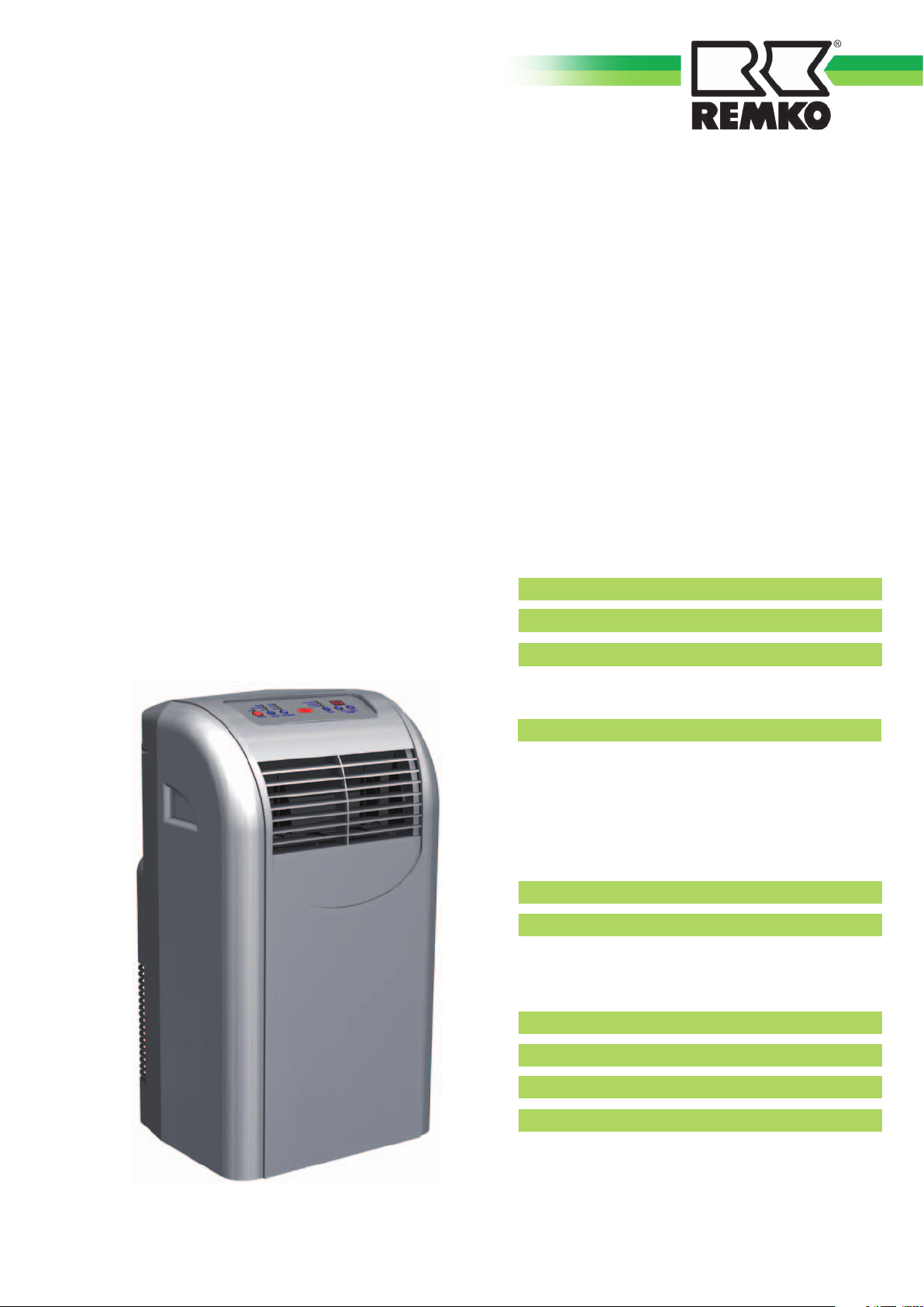
REMKO MKT 250
Portable Air Conditioner
Operation • Technology • Spare Parts
Safety Notices
2
Scope of Supply
2
Device Structure
3
Erecting the Device
3
Exhaust Air Conductance
3
4-5
6-7
8-12
10
11
12
Operation
Control Panel and Remote Control
4
“Mode“ Selection
4
“Cool“ Mode
5
“Dehumidify“ Mode
5
“Fan“ Mode
5
“Timer“
5
Functional Principle of the Cooling Process
6
Maintenance and Care
Cleaning the Filter
6
Draining the Condensate
6
Trouble Shooting
7
Taking the Device Out of Service
8
Warranty
8
Environment and Recycling
9
Technology
Electrical Wiring Diagram
8
Installation Instructions for the Wall Bushing
9
Device Diagram
Spare Part List, Accessories
Technical Data
Edition GB – T12
Page 2
REMKO MKT
Safety Notices
Before delivery, this device was sub-
jected to numerous material, function,
and quality tests. Nevertheless, the
device may present a danger if used by
untrained personnel, improperly, or not
according to regulation!
Caution
Operation other than as de-
scribed in these instructions is
prohibited. Nonobservance leads
to the extinguishment of any
liability and warranty claims.
Observe the following notices:
■ The device is not suited for out-
door operation.
■ The device may not be set up and
operated in rooms at risk of explo-
sion and in atmospheres containing
oil, sulphur, or salt.
■ Make sure it is at a sufficient
security distance to inflammable
objects.
■ Do not place any objects on the
device.
■ Observe the minimum clearances
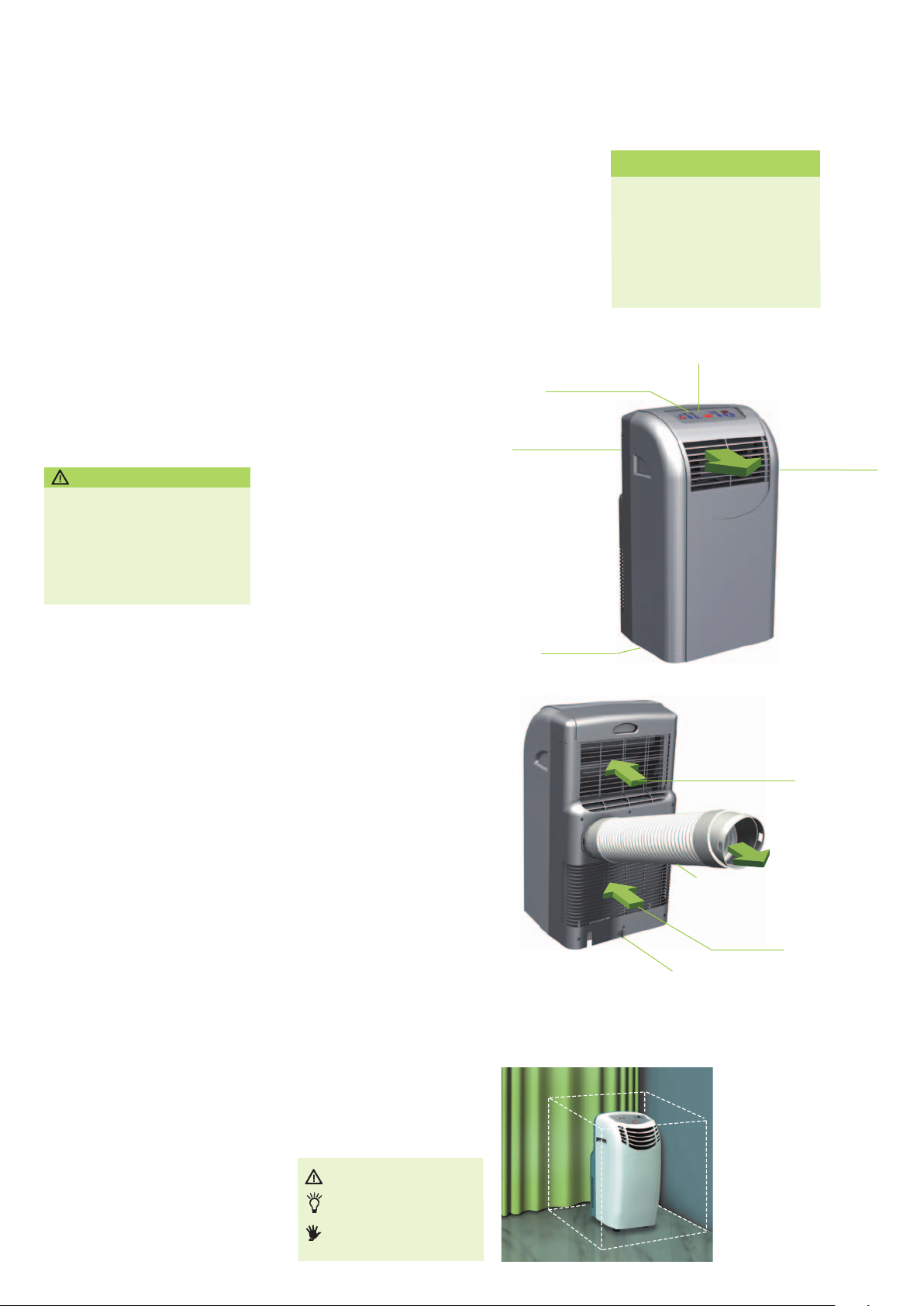
(Fig. 2).
■ Do not insert any objects into air
inlets and outlets.
■ Erect the device on an even, stable
surface. Never place it on its side
(Fig. 3).
■ Operate the device only when it is
upright.
■ Do not expose the device to direct
water spray.
■ Operate the device only within its
permissible operating limits (16 to
35°C).
■ Do not pull on or bend the mains
supply line.
■ Protect all electrical lines of the
■ Select the extension lines of the
■ Do not lay lines under carpeting.
■ Never operate the device with-
■ Never direct the air flow at
■ Never open the device housing
■ Work on the cooling system and
Transporting the device
■ Before transport, switch off the
■ Transport the device only in an
■ We recommended that any
■ After every transport of the
device from damage, even from
animals.
mains supply line depending on
the connected load of the device,
the line length, and the intended
use.
out an air filter.
people.
as there is a danger of an electri-
cal shock.
the electrical equipment may be
carried out only by an
authorised specialist.
device and pull the mains plug.
upright position.
condensate be drained using the
condensate drain spout on the
back side of the device before
transport.
device, wait at least 5 minutes
before recommissioning it
(Fig. 4).
CAUTION
TIP
DANGER
Infrared receiver
Recessed grip
Transport
rollers
Fig. 1
MKT 250
Scope of Supply
1 MKT 250 air conditioner
1 Infrared remote control
2 Batteries (type AAA/1.5 V)
1 Air outlet hose with connection
pipe adapter and window jet
Control panel
Air inlet
(circulation air)
with air lter
Air outlet
hose
Air inlet
(exhaust air)
Condensate drain spout
with plug
Fig. 2
Minimum clearances
Side 500 mm
Front 500 mm
Rear 400 mm
Top 100 mm
Air directing
plate ns
Exhaust air
outlet
3
Page 3
Device Structure
Delivery
All devices are carefully packed
before shipping. Please check the
device immediately after delivery.
Make a note of any damage or
missing parts on the delivery note
and inform the forwarding agent
and your contractual partner. No
warranty can be assumed for later
complaints.
Erecting the device
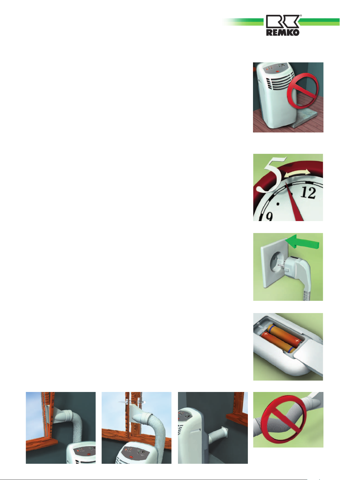
■ Make sure that all air intake
and air outlet openings are
free; observe the minimum
clearances (Fig. 2).
■ Erect the device on a solid,
even foundation (Fig. 3).
■ Make sure that people and
sensitive objects such as plants
are not directly affected by the
emerging air.
■ Connect the device to a
properly installed plug socket
(230V/50Hz) (Fig. 5).
■ Insert the batteries into the
remote control. To do so,
push up the cover on the back
side of the remote control
and insert the batteries while
observing the proper polarity.
Observe the marking inside
the compartment (Fig. 6).
■ Check whether the plug of the
condensate drain spout has
been provided and whether
it has been properly inserted.
There is otherwise a danger of
water emerging.
Exhaust air conduction
During the operation of the air
conditioner, the device creates
humid exhaust air that must be
conducted outside of the room
so that the cooling effect can be
maintained.
Observe the following notices:
■ Plug the air outlet hose in-
cluded in delivery onto the air
outlet on the rear panel of the
device.
■ Lock both catches on the air
outlet into both openings of
the air outlet hose.
■ Keep the air outlet hose as
short as possible (max. length
1400 mm).
■ Always lay the air outlet
hose with a constant upward
incline from the device to the
wall/window. Make sure it has
a wide curve radius (Fig. 7).
■ The air outlet hose may not be
extended.
■ Pivot-hung windows
· Connect the air outlet hose to
the window jet and the de-
vice.
· Open the window and lay the
flat nozzle between the win
dow trim and the window
frame (Fig. 8).
■ Double-wing window
Lay the flat nozzle between
the wings, close the window
as far as possible, and secure
the wings with a holding strap
(Fig. 9).
■ Wall bushing
In case of permanent instal-
lation (s. p. 9, Fig. 19), the
exhaust air from the device is
conducted outside the room
through the wall bushing
(Fig. 10).
Fig. 3
Vertical erection on
solid, even foundation
Fig. 4
Five-minute “wait“
Fig. 5
230 V / 50 Hz
Fig. 8
Hanging the window jet
into a pivot-hung window
Fig. 9
Secure the double-wing
window using a holding strap.
Fig. 10
Permanent installation
with a wall bushing (accessory,
not included in supply schedule)
Fig. 6
Remote control
Abb. 7
Attach the air outlet
hose with a constant upward
incline
4
Page 4
REMKO MKT
Operation
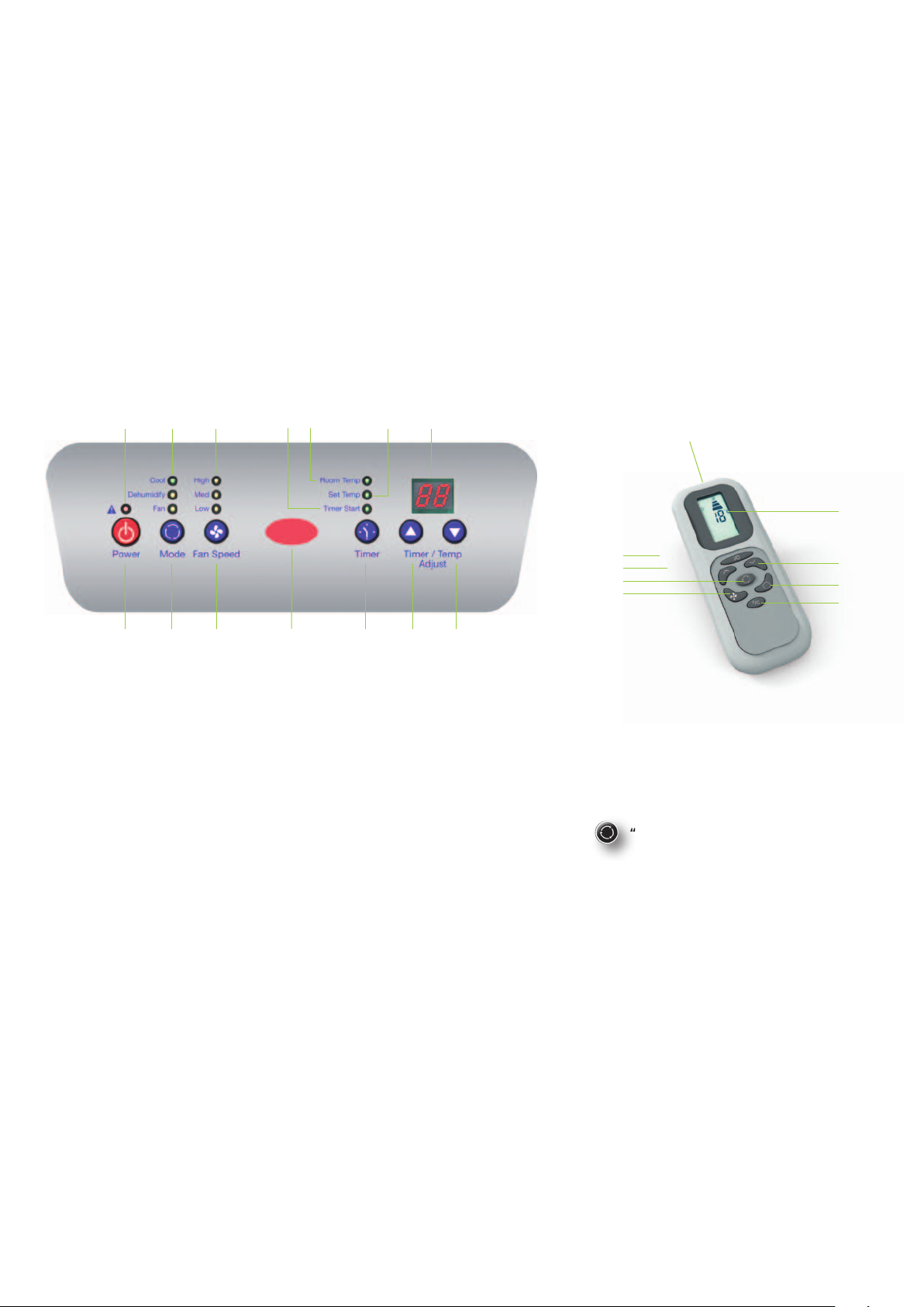
The device is operated comfortably using
the control panel on the device or the in-
frared remote control. Keys with the same
symbols have the same function.
8 9 10 11 12 13 7
Infrared
receiver
Fig. 11
Control panel
1
2 3 4 5 6
■ Point the infrared transmitter of the
remote control at the infrared receiver
on the control panel.
■ In order for the signal to be received
without interference, there should be
no objects between the remote control
and the device (reach of approx. 5 m).
■ The proper reception of the signal is
indicated acoustically.
Infrared
transmitter
1
5
2
3
Fig. 12
Infrared remote control
7
6
4
14
1 On/off “Power“ button
2 “Mode“ button
3 “Fan Speed“ button
4 “Timer“ button
5+6 Temperature/time setting buttons
“Timer/Temp. Adjust“: 5 higher, 6 lower
7 Display
8 Red fault LED: Reservoir full (s. p. 7 Trouble Shooting)
An acoustic and an optical signal indicate that the oat switch of the internal
reservoir has shut down the operation of the device. The acoustic signal dies
down after a short period of time, but the LED remains active.
9 Mode LED
Green: “Cool“
Orange: “Dehumidify“
Yellow: “Fan“
10 Orange LED for the fan speed, with high/medium/low speed “High“/“Med“/
“Low“
11 Green LED for the time delay, “Timer“
12 Green “Room Temp“ LED
(If this LED lights up the current room temperature is shown in the display (7))
13 Green “Set Temp“ LED
14 “°C/°F“ toggle button (only on the remote control)
“Mode“ selection (2)
■ “Cool“
The device is used to cool the room. It filters
and dehumidifies the air and thus creates a
pleasant room climate.
■ “Dehumidify“
In the “Dehumidify“ mode, humidity is
removed from the air.
■ “Fan“
The device circulates the air, filters it, and
creates an even air flow.
5
Page 5
“Cool“ mode
“Dehumidify“ mode
“Timer“ time delay (4)
1. Attach the air outlet hose to the wall
bushing or the window.
2. Activate the device using the “Power“
button (1) .
3. Press the “Mode“ button (2) until the
“Cool“ LED (9) lights up.
4. Select the fan setting using the “Fan
Speed“ button (3):
“High“ highest speed
“Med“ medium speed
“Low“ lowest speed
5. If the “Room Temp.“ LED (12) lights up,
the current room temperature is shown
in the display (7).
6. As soon as the (4/5/6) button is
pressed, the display switches from the
room temperature to the set tempera-
ture (LED 13 lights up) and shows the
desired temperature for 15 seconds.
7. Set the desired room temperature using
the “Timer/Temp. Adjust“ button (5/6).
The up arrow (5) increases the set value
shown in the display (7), while the
down arrow (6) decreases it.
TIP
“Cool“ mode
1. Attach the air outlet hose to the wall
bushing or the window.
2. Activate the device using the “Power“
button (1).
3. Press the “Mode“ button (2) until the
“Dehumidify“ LED (9) lights up; the fan
is automatically switched to the “Med“
or medium fan speed stage.
“Fan“mode
1. Activate the device using the “Power“
button (1).
2. Press the “Mode“ button (2) until the
“Fan“ LED (9) lights up.
3. Select the fan setting using the “Fan
Speed“ button (3):
“High“ highest speed
“Med“ medium speed
“Low“ lowest speed
4. The room temperature is not influenced
and remains constant. For this reason,
the temperature and time setting
“Timer/Temp. Adjust“ buttons (5/6)
cannot be used.
You can turn the device on and off
automatically using the timer. To do so,
an activation/deactivation delay is pro-
grammed.
■ Automatic activation
1. Activate the device using the
“Power“ button (1).
2. Select the mode and make all set-
tings for the desired mode.
3. Deactivate the device using the
“Power“ button (1) .
4. Press the “Timer“ button (4).
5. Set the time using the “Timer/
Temp. Adjust“ button (5/6).
Only whole hours can be entered.
6. The LED (11) flashes.
7. The device activates automatically
at the set time.
■ Automatic deactivation
1. The device is running in the previ-
ously set mode.
2. Press the “Timer“ button (4).
3. Set the remaining run time using
the “Timer/Temp. Adjust“ button
(5/6).
Only whole hours can be entered.
4. The LED (11) flashes.
5. The device deactivates automati-
cally at the set time.
You can achieve a pleasant
room climate by selecting
a set temperature that is a
maximum of 4 to 7°C below
the outdoor temperature.
6
Page 6
REMKO MKT
Cooled circulation
air in the room
Ventilator
(exhaust air)
Fig. 13
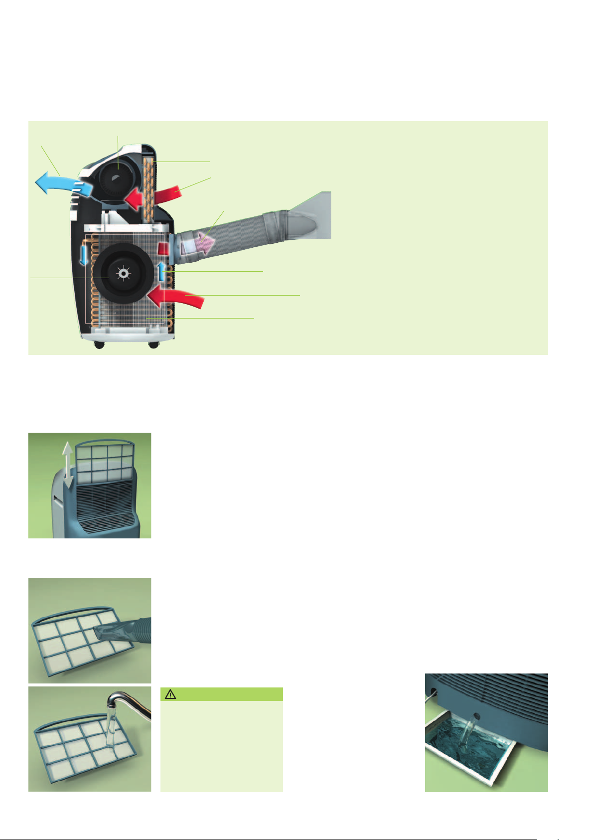
Functional principle of the cooling process
Fan (circulation air)
Maintenance and Care
Evaporator
Air inlet (circulation air)
with air lter
Warm exhaust air
outside
Cooling circuit
Air inlet (exhaust air)
Condenser
Functional principle of
the cooling process
The air conditioner
cools the air by re-
moving heat from it.
The fan (circulation
air) conducts cooled
air into the room. The
heat that the device
has removed from the
air is conducted out-
side via the air outlet
hose.
Humidity is removed
from the air and drips
as condensate from the
evaporator onto the hot
condenser and evapora-
tes. Excess condensate
drips from the condenser
into a collection tray
and conducted from
there to the condenser
again using a rotor,
evaporated, and then
conducted away with
the exhaust air ow.
Fig. 14
upwards from the machine
Removing the air lter
With low cleaning effort, you
can guarantee malfunction-free
operation and a long service
life.
■ Use only mild, environment-
friendly cleaning agents.
■ Regularly clean the
ventilation slots.
■ Clean the device as required,
but at least once a year, with
a moist cloth and lukewarm
water.
■ Do not expose the device to
direct water spray.
CAUTION
Always turn off the device
and pull the mains plug before
cleaning!
Cleaning the air filter
Clean the air filter regularly,
but at least every 100 operat-
ing hours. In case of strongly
contaminated air, the period is
reduced accordingly.
1. Switch off the device and
pull the mains plug.
2. Remove the filter from the
device (Fig. 14).
3. Clean the filter using a
vacuum cleaner or, in case
of heavy soiling, carefully
using lukewarm water (Fig.
15/16).
4. Let the filter air-dry and then
reinsert it.
Draining the condensate
■ The condensate evaporates
during operation and is then
conducted outside with the
exhaust air via the air outlet
hose.
■ In case of extreme humidity,
the device collects conden-
sate in a reservoir. If the
permissible level is exceeded,
the red fault LED lights up
and the device shuts down.
■ The reservoir must be
emptied via the condensate
drain spout (Fig. 17).
Never operate the device
without the air lter.
Fig. 15 /16 Cleaning the air filter Fig. 17
7
Draining the condensate
Page 7
Trouble Shooting
The device is not functioning and the
control panel remains dark.
■ Make sure that
· the mains plug is properly inserted;
· there is no power failure;
· the mains voltage is present (fuse)
■ Check the mains supply line for damage.
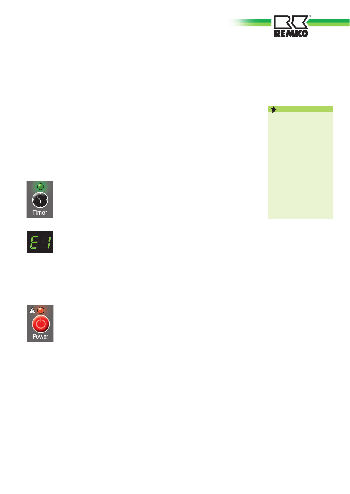
The device is not functioning and the
“Timer“ time delay LED is flashing.
■ “Timer“ time delay is programmed.
Delete the timer setting.
The device is not functioning and
“E1“ is being shown in the display.
■ The room temperature lies outside the
operating range of 16 to 35°C. Wait
until the room temperature lies in the
working range (reduce the incident of
sunlight and close windows and doors,
if necessary).
The device deactivates automatically.
The fault LED flashes and a signal sounds
(reservoir full).
To drain the reservoir, proceed as follows:
1. Switch off the device and pull the mains
plug.
2. Place a flat tray under the condensate
drain spout and remove the plug (Fig.
17).
3. After the condensate has drained,
reinsert the plug firmly.
The device is not cooling properly.
■ Check the mode: the “Cool“ LED must
be lit.
■ For an optimum cooling capacity, close
the curtains and blinds. In addition,
make sure the windows and doors are
closed.
■ Make sure that
· the air outlet hose has been prop-
erly attached. It may not be bent,
declining, or laid in a tight curve;
· no foreign bodies impair the ex-
haust or intake air supply (observe
the minimum clearances);
· the air directing plate fins are free of
soiling or foreign objects
· the set temperature is not too high
(operating limits of the device: 16
to 35°C).
The device does not react
to the remote control.
■ Make sure that
· the batteries are functioning;
change them if necessary;
· the batteries are inserted with the
correct polarity (cf. the marking);
· there are no objects between the
remote control and the device
(reach of approx. 5 m).
Condensate is emerging.
■ Make sure that
· the device is on a horizontal
foundation;
· the air outlet hose is properly at-
tached;
· the plug is firmly inserted in the
condensate drain spout.
DANGER
Contact your dealer or
contractual partner if the
device cannot be com-
missioned.
Never open the device
housing.
Never perform work on
the cooling circuit or the
electrical equipment.
8
Page 8
REMKO MKT
Electrical wiring diagram
Control panel
Microswitch
Temperature
sensor
Technical dimensions and design subject to alteration
J003 J002 J001
Evaporator fan
Red
Orange
Yellow
Hi
Med
Lo
J01
RL101
COMP
Blue
L
Blue
L
Blue
Blue
Brown
Red
Red
Red
White
White
Blue
Condenser
L N
E
White
Mains plug
Blue
Condenser Condenser
Compressor Evaporator fan Reservoir motor
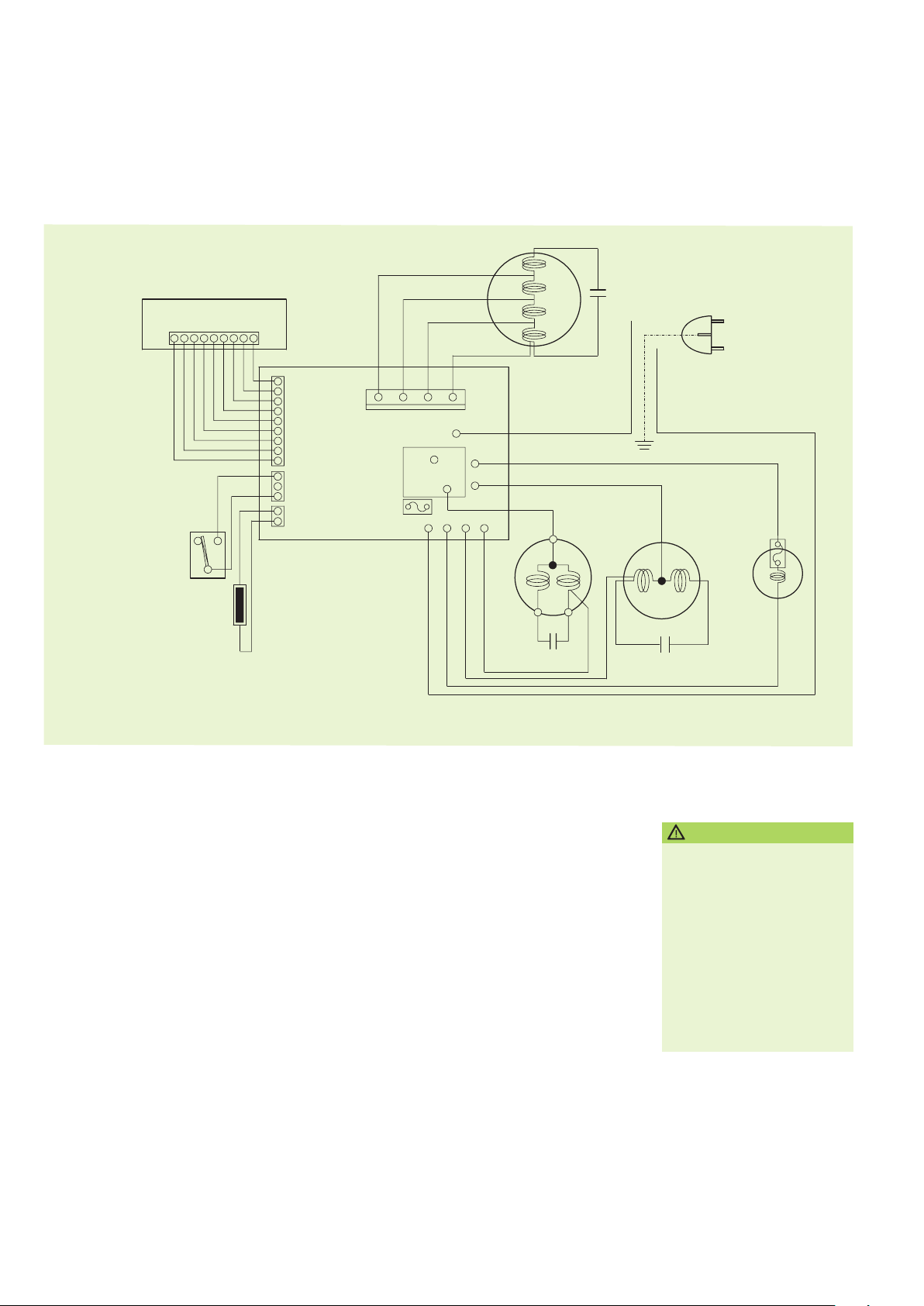
Fig. 18
Electrical wiring diagram
Taking out of service
To take the device out of service,
deactivate it first by pressing the “Power“
button. Then pull the mains plug.
If the device must be shut down for a
longer period of time, for example, for
storage during the winter, observe the
following:
1. Let the machine run for about two
hours in the “Fan“ mode to dry the sur-
face of the evaporator plate fins. In this
way, the residual moisture is removed
from the device and you can prevent
unpleasant smells during recommission-
ing.
2. Switch off the device, pull the mains
plug, and roll up the mains supply line.
3. Drain the condensate (s. p. 6).
9
Warranty
■ The function of the device was precisely
checked several times at the factory. If
malfunctions that are not described in
the “Trouble Shooting“ chapter (s. p.
7) still appear, contact your dealer or
contractual partner.
■ In order for REMKO to assume the
warranty, the “Warranty Certificate“
included in delivery must be completely
filled out and sent to REMKO GmbH &
CO KG immediately after purchasing or
commissioning.
CAUTION
The manufacturer is not li-
able for damage that occurs
due to nonobservance of
manufacturer instructions or
the legal requirements or due
to unauthorised changes to
the device.
Page 9
Disposal of the old
device
The unit production is subject to
continuous quality control.
Only high-quality materials are used,
the majority of which are recyclable.
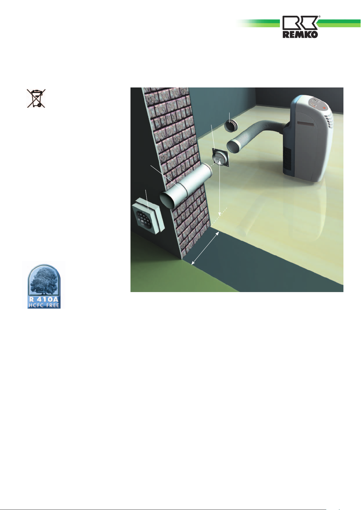
Fig. 19
Installation diagram
for the wall bushing
Sealing cap
Trap
You also contribute to environmental
protection by guaranteeing that your
old equipment is disposed of in an
environmentally friendly manner.
For this reason, bring the old equip-
ment only to an authorised recycling
company or to a corresponding
disposal site.
Environment and Recycling
Telescopic
pipe
Protective
grille
min. 400 mm
max. 480
mm
Installation Instructions for the Wall
■ Dispose of the packaging in an
ecofriendly manner.
■ Do not dispose of the device in
domestic rubbish.
■ Both the refrigerant and the plant parts
are subject to special disposal
conditions.
■ The refrigerant used belongs to the
chlorofluorocarbon refrigerant group. If
it is released into the air due to damage
to the cooling circuit, injury to the respi-
ratory organs of people and animals will
not occur.
■ Create a core hole in the outside wall
(max.- wall thickness of 480 mm) with a
diameter of at least 135 mm.
■ Take the minimum distance of 430 mm
between the floor (mounting surface of
the device) and the centre of the wall
bushing into consideration.
■ Insert the telescopic pipe into the wall
bushing
■ To prevent cold bridges, insulate the
telescopic pipe with suitable insulating
material.
■ Wall the telescopic pipe into the core
hole in such a way that it is flush to both
sides of the wall.
■ Mount the protection grill on the out-
side of the wall (make sure it is protect-
ed from rain).
■ Fix the trap to the inside.
■ The “top“ label on the trap must be
legible from the inside!
■ When taking the device out of service,
for example, at the beginning of winter,
close the opening of the trap using the
sealing cap to prevent air circulation.
10
Page 10
REMKO MKT
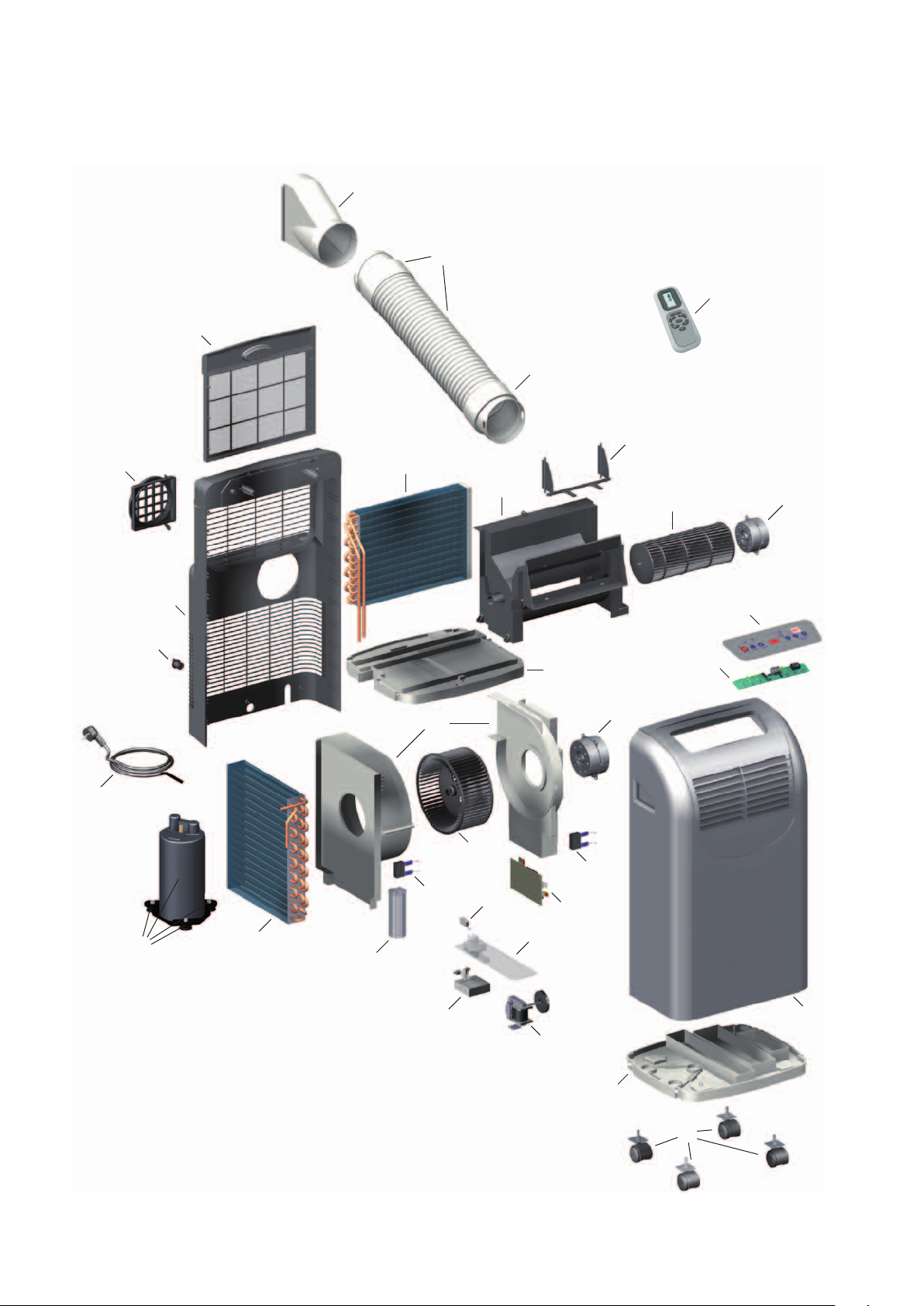
Device Diagram
28
31
29
33
30
25
22
15
32
24
17
11
16
12
18
14
13
4
7
21
19
26
20
27
11
8
Technical dimensions and design
subject to alteration
10
6
9
5
3
1
2
Fig. 20
Device diagram of the MKT 250
23
Page 11
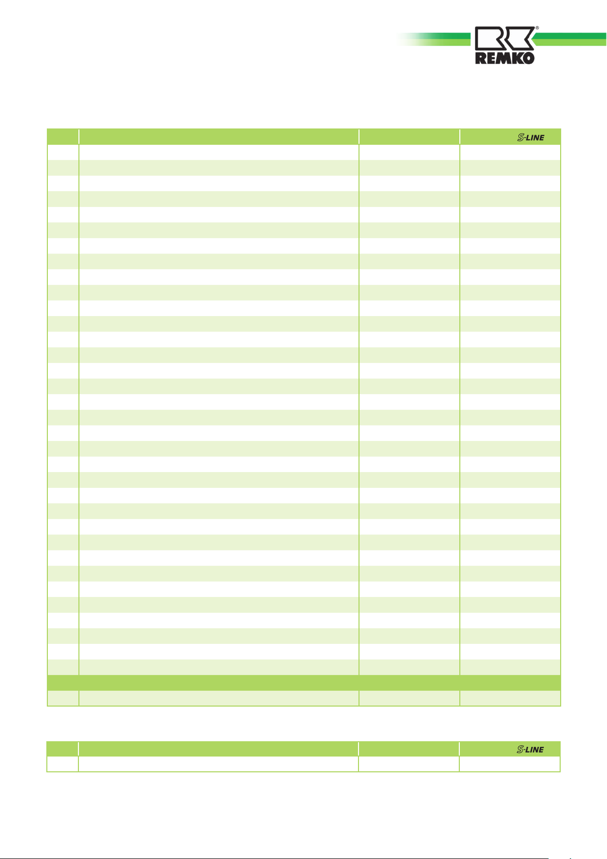
Spare Part List
No.
Designation
1 Unit bottom 1106850 1106850
2 Transport roller 1106851 1106851
3 Condensate pump 1106852 1106852
4
Condenser 2.5 µF (evaporator fan)
5 Float regulator (reservoir) 1106854 1106854
6 Cover (reservoir) 1106855 1106855
7
Microswitch (reservoir)
8
Compressor, cpl
9 Condenser 40 µF (compressor) 1106892 1106892
10 Evaporator 1106893 1106893
11 Fan housing (exhaust air) 1106860 1106860
12 Fan wheel (exhaust air) 1106861 1106861
13 Fan motor (exhaust air) 1106863 1106863
14 Condensate tray 1106824 1106824
15 Exhaust air pipe adapter 1106865 1106865
16 Condenser 1,5 µF 1106866 1106866
17 Evaporator 1106894 1106894
18
Fan housing (circulation air)
Fan wheel (circulation air)
19
20 Fan motor (circulation air) 1106843 1106843
21 Circuit board 1106873 1106873
22 Mains supply line with plug 1106874 1106874
23 Front wall 1106820 1106827
24 Back wall 1106829 1106829
25 Air outlet segment 1106844 1106844
26 PCB with control 1106825 1106825
27 Control panel 1106826 1106831
28 Air filter 1106830 1106830
29
Entry circuit
Connection pipe adapter
30
Window jet
31
32 Condensate drain spout with plug 1106882 1106882
33 Remote control 1106884 1106884
Air outlet hose, cpl. (nr. 29; 30; 31) 1106885 1106832
Spare parts without Abbildung
Sensor (circulation air) 1106889 1106889
MKT 250
1106853 1106853
1106856 1106856
1106891 1106891
1106822 1106822
1106823 1106823
1106886 1106833
1106887 1106834
1106888 1106835
MKT 250
Accessories
No.
Designation
Wall bushing 1613115 1613115
When ordering spare parts, enter the serial of the device on the rating plate in addition to the Ref. no.
MKT 250
MKT 250
12
Page 12
REMKO
Your Competent Partner for
Air-conditioning • Heating • Dehumidication
REMKO GmbH & Co. KG
Air-conditioning and heating technology
Im Seelenkamp 12 · 32791 Lage, Germany
P.O. Box 1827 · 32777 Lage, Germany
Phone +49-5232-606-130
Fax +49-5232-606-260
E-mail [email protected]
URL www.remko.de
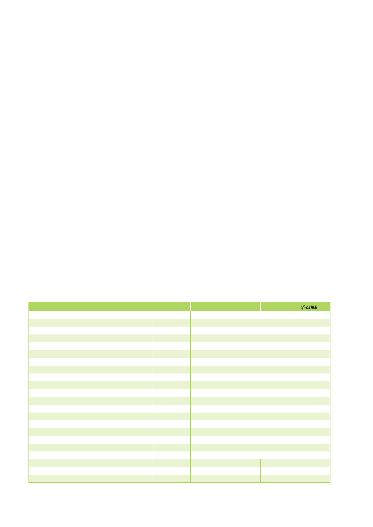
Technical Data
Device type
Nominal cooling capacity
Energy efficiency class, cooling A
Energy efficiency factor EER
Application range (room air volume), approx. m³ 80
Temperature setting range °C +16 up to +32
Temperature operating limits °C /%r.F. +16 bis +35 / +35 bis +85
Refrigerant R 410A
Operating pressure max., cooling circle kPa 1900 / 2800
Refrigerant quantity kg 0,65
Circulation air volume flow rate m³/h 240 / 270 / 320
Sound pressure level
Voltage supply V/Hz 230 / 1~ / 50
Type of protection IP 20
Power consumption
Current consumption
Electrical starting current
Air outlet hose, diameter
Diemsions height/width/depth mm 700
Weight kg 32,0
Color white silver
Serial no. 920... 921...
Ref.no. 1612250 1612251
1) Room temperature dry-bulb DK 35°C / wet-bulb VK 24°C
2) Distance 1 m
1)
1)
2)
1)
1)
kW 2,62
dB(A) 45 / 50 / 53
kW 0,99
A 4,56
A
mm/mm
MKT 250
MKT 250
2,65
21
1200 / 125
 Loading...