

Page 1
REMKO
WIRELESS REMOTE CONTROL
FOR MULTITALENT HEAT PUMP MANAGER
Operation - Technology - Spare parts
Edition GB –B09
Page 2

Page 3

Contents
Safety notes
Environmental protection and recycling
Warranty
Intended use
Transportation and packaging
Unit description
Operation
Troubleshooting and customer service
Installation
Commissioning
Changing the battery
System bus
Technical data
4
4
4
4
4
5
5-25
26-27
28
28
29
29
30
Made by REMKO
Read these operating instructions carefully before commissioning/
using the unit!
These instructions are an integral part of the unit and must always be
kept in the vicinity of the installation location or on the
unit itself.
This operating manual is a translation of the German original.
Subject to modifications; no liability accepted for errors or misprints!
3
Page 4

REMKO WIRELESS REMOTE CONTROL
FOR MULTITALENT HEAT PUMP MANAGER
Safety notes
Carefully read the operating
instructions before commissioning
the unit for service. It provides
useful tips and information as
well as hazard warnings to prevent
injury or material damage .
Failure to follow the directions
in this manual can endanger
persons, the environment and
the equipment itself and will void
any claims for liability.
■ Keep this manual close to
the equipment.
■ Modification of the units
and components supplied
by REMKO is not permitted and
can cause malfunctions.
■ Operating equipment
or components with obvious
defects or damage is not
permitted.
■ Do not operate units or
components if there are obvious
defects or signs of damage.
■ Repairs may only be carried out
by authorised personnel, while
cleaning may be carried out by
the operating company.
■ The units or components
are not to be exposed to
any mechanical stresses,
extreme levels of humidity
or direct sunlight.
Environmental
protection
and recycling
Disposing of packaging
All products are packed for
transport in environmentally
friendly materials. You can make
a valuable contribution to reducing
waste and sustaining raw materials
by only disposing of packaging at
approved collection points.
Disposing of the units
and their components
Only recyclable materials are used
in the manufacture of the units
and components.
Help protect the environment
by ensuring that the units
or components (for example
batteries) are not disposed of in
household waste, but only in
accordance with local regulations
and in an environmentally safe
manner, e.g. using authorised
disposal and recycling specialists or
council collection points.
Warranty
The precondition for all warranty
claims is that the orderer or his
customer has fully filled out the
"warranty registration card"
supplied with the unit, at the
time when it was purchased and
commissioned, and returned it to
REMKO GmbH & Co. KG.
The warranty conditions are
listed in the "General terms and
conditions". Furthermore, only the
parties to a contract can conclude
special agreements beyond these
conditions. For this reason, please
contact your contractual partner
first.
Intended use
The purpose of the units is
the entry and display of system
parameters for the Multitalent heat
pump manager.
Any different or additional
use is a non-intended use.
The manufacturer/supplier assumes
no liability for damages arising from
a non-intended use. The user bears
the sole risk in such cases.
Intended use also includes working
in accordance with the operating
and installation instructions and
complying with the maintenance
requirements.
Transport and
packaging
The units are shipped in sturdy
transport packaging. Immediately
check the units on delivery and
make a note of any damage or
missing parts on the delivery note.
Inform the forwarding agent and
contractual partner. Warranty
claims at a later date will not be
accepted.
4
Page 5
Unit description
The wireless remote control allows
the Multitalent heat pump manager
to be regulated by weather
conditions or room temperature.
It makes it possible for the owner
to easily input and view system
parameters (e.g. time, current hot
water target temperature) and
heating circuit parameters (e.g.
heating times and desired room
temperature) from their living
space. This allows the heating
system to be regularly monitored
and optimised.
With the wireless remote control, it
is also possible to make a correction
to the weather-driven control
system by means of a roomtemperature-controlled cutout.
Operation
After inserting the batteries, the
Installation menu appears once
only. After adjusting the values
contained on the menu, the
controller is ready for operation.
If the menu appears later, e.g.
after a power cut, the function can
simply be exited.
Installation is initiated by
pressing “OK” (see the chapter
“Installation”).
Installation can be cancelled by
pressing “Cancel”.
C
B
A
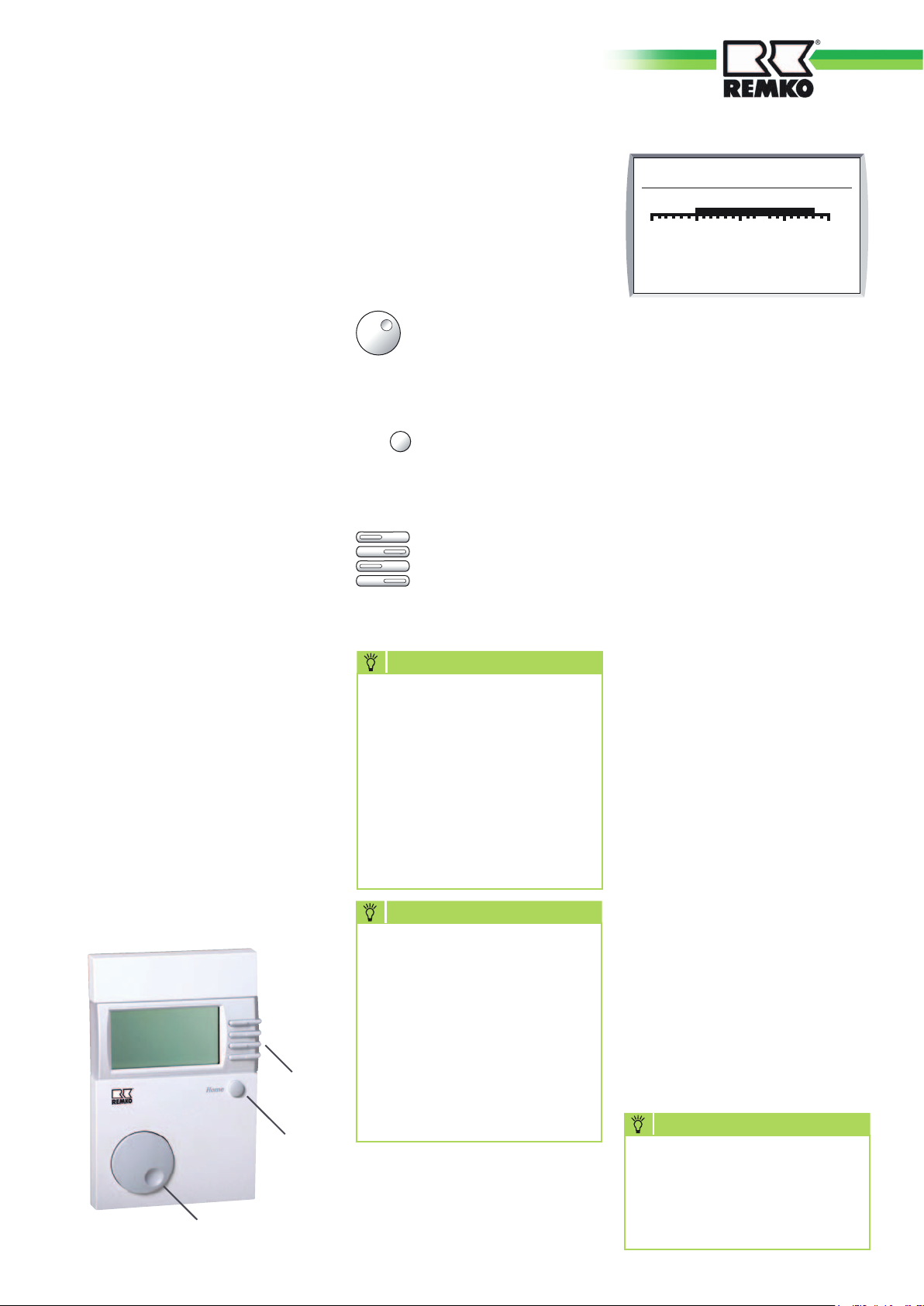
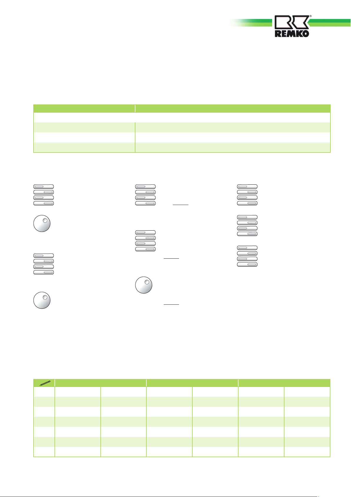
Controls during
normal operation
The wireless remote control is
controlled with the following keys.
The rotary knob (A)
can be used to toggle
between the displayed
menu points or to change
the settings.
Pressing the Home key
Home
(B) always returns you to
the standard display.
Each of the four function
keys (C) stands for one
of the four rows on the
display. Pressing an F-key
serves to select a menu
item or setting.
NOTE
The current heating
programme and hot water
programme for the room
controller are permanently
displayed on row [2] of
the Favourites menu.
The associated heating circuit
number of displayed in
brackets. You can program all
the other favourites yourself.
NOTE
Due to the tolerances
of the sensors, deviations of
+/- 2K (2°C) between different
temperature indicators are
normal. In the case of rapid
temperature changes, these
deviations will intermittently
be higher due to the differing
time response of different
sensors.
Display / function keys
The standard display of the
wireless remote control of the
heat pump manager is comprised
of four rows.
Mon 08:3030 Mar 09
0
Room temp.
Standby
12 24
1
(1)
20.5 °C
External
Row 1: This displays the day of the
week, the date and time.
By pressing the F-key you can
adjust the date, time and holidays.
Row 2: Display the favourites.
You can select from the currently
displayed favourites with the
rotary knob (A).
By pressing the F-key you can
adjust the Favourites or the
additional indicator.
The following predefined options
are stored:
- Hot water programme
- Heating programme (HC number)
- Outdoor temp.
- HA temp.
- HW temp.
- Supply temp.
- Enable heating circuit
- HW demand
- Burner 1
Row 3: Room temperature
indicator.
Pressing the F-key allows you
to adjust the selected room
temperature.
Row 4: Displays the operating
mode and the current situation
(Heating, Reduction, Party, eco or
Holiday).
By pressing the F-key, you can
adjust the operating mode and
select the Party, Reduction, or
Holiday function (this applies to all
internal heating circuits).
NOTE
Deviations in the respective
parameters can no
longer be displayed after
the wireless remote control is
commissioned.
5
Page 6
REMKO WIRELESS REMOTE CONTROL
FOR MULTITALENT HEAT PUMP MANAGER
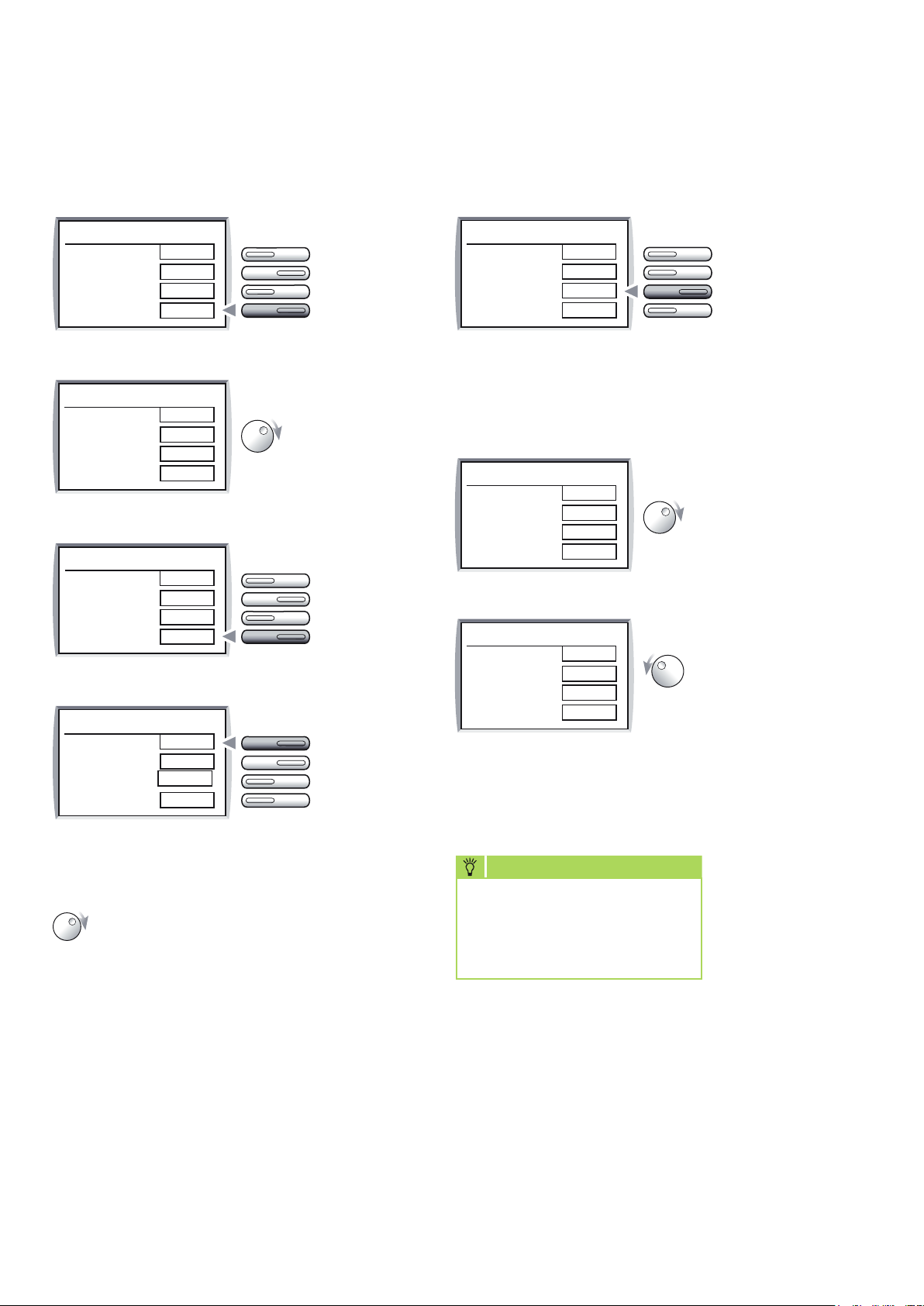
Setting the operating mode
Operating mode
Cancel
Automatic 1
Party
Reduction
OK
Operating mode
Cancel
Automatic 1
Party
Reduction
OK
Operating mode
Cancel
Automatic 1
Party
Reduction
OK
Operating mode
Cancel
Automatic 1
Party
Reduction
OK
During normal
operation, press
the F-key next
to “OK”.
Set the desired
operating mode
with the rotary
knob.
The selected
mode is
confirmed
and saved by
pressing the
F-key next to
“OK”.
The action
is cancelled
without saving
by pressing the
F-key next to
“Cancel”.
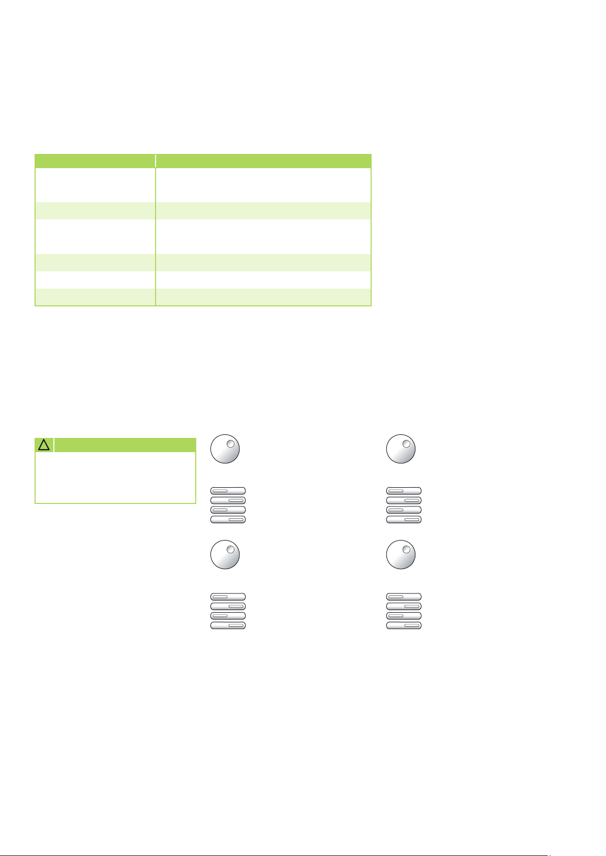
Setting the Party, Reduction, and
“Immediate Holiday” function
Pressing the
Operating mode
Cancel
Reduction
01 h 00 min
Party
Reduction
OK
F-keys next
to “Party”
(heating time
extension) or
“Reduction”
(heating time
interruption)
selects the
corresponding
operating mode.
Operating mode
Cancel
Reduction
01 h 00 min
Party
Reduction
OK
Operating mode
Cancel
Reduction
05 days
Party
Reduction
OK
Turning the
rotary knob
clockwise sets
the hours.
Turning the
rotary knob
clockwise sets
the hours.
This makes it easy to quickly raise or reduce
the heating temperature for the rest of the day,
or to set a holiday programme starting immediately
(e.g. Reduction 5 days).
Overview of the operating modes
When an operating mode is selected, it is shown
on the screen. It takes effect once the setting
has not been modified for 5 seconds.
You can choose from the following operating modes:
Standby / OFF
(Heating OFF and Water
heating OFF, Frost
protection function only)
Automatic
operation 1
(Heating acc. to Time
programme 1; HW acc.
to HW programme)
Automatic
operation 2
(Heating acc. to Time
programme 2; HW acc.
to HW programme)
6
NOTE
Eco Comfort switchover: occurs at <> 1 K from target
room temp. to actual room
temp.
Summer operation
Heating/
Eco Comfort
Heating/
Reduction
(Heating OFF, HW acc.
to HW programme).
(24h heating with Comfort
temperature 1, HW acc. to
HW programme)
(24h heating with Reduction
temperature, HW acc. to
HW programme)
Page 7
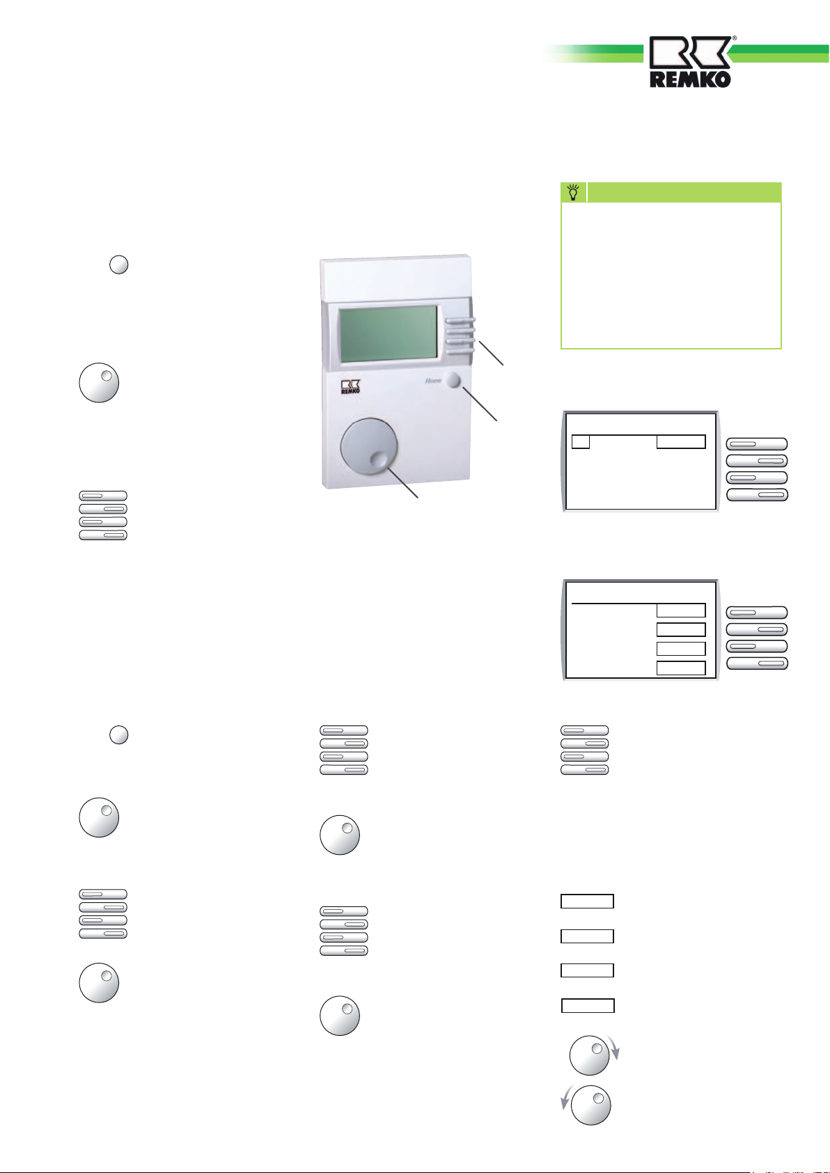
Controls in operating mode
The wireless remote control used to regulate the heat pump manager
is controlled in operating mode with the following keys.
Home
Pressing the Home
key (B) takes you from
operating the controller
to normal operation
(standard display)
Using the rotary knob
C
(A), you can move
through the menus,
move through settings/
B
parameters, or adjust
the selected value.
Each of the four function
keys (C) stands for one
A
of the four rows on the
display. Pressing an
F-key selects the adjacent
menu, value or function.
NOTE
If a parameter, a function/
display or a parameter menu
is not supported by the
connected heating circuit
controller, it is hidden or this
is indicated on screen with
dashes.
Display in operating mode
Main menu
01
Display
User
Time programmes
Cancel
Display during value entry
Target room temp. 1
20.0 °C
Cancel
Favourite
Default
OK
Basic operating procedure
Home
Pressing the Home key
takes you to operating
mode.
Move through the menu
items (types of setting)
with the rotary knob,
e.g. Display, User, etc.
Use the corresponding
F-key to select the item
you chose above.
With the rotary knob,
choose a sub-menu (Appliance / Consumer),
e.g. System (heating
appliance), Hot water,
Heating circuit.
Use the corresponding
F-key to select the submenu you chose above,
e.g. Hot water.
Choose the setting/display value with the rotary
knob. The current value
is displayed.
Use the corresponding Fkey to select the setting/
display value you chose
above.
Use the rotary knob to
change the setting.
Select the function with
the corresponding F-key.
Confirm the change
or cancel by pressing
“Cancel”, “Favourite”,
“Default” or “OK”
The function keys perform the
following roles:
Cancel
Cancel the current
function without saving
Favourite
Carry over setting to
Favourites menu
Default
Change setting value to
factory setting
OK
Cancel the current
function and save
Next setting (e.g. time:
Hour->Minute)
Previous setting (e.g.
date: Month<-Year)
7
Page 8

REMKO WIRELESS REMOTE CONTROL
FOR MULTITALENT HEAT PUMP MANAGER
Overview of the operating menus
Menus Description Sub-menus Description
System
All display values and settings relating to the heating
appliance or the system as a whole, or which cannot
be assigned to another consumer circuit.
Display
User
Time
programme
Displays system values
(e.g. sensor and target values).
Adjustment is not possible.
This means that operating errors
in this menu are not possible.
Summary of settings that can be
adjusted by the operator.
Summary of the time
programmes for the heating
circuits, the hot water circuit
and additional functions, as
applicable
Hot water
Heating circuit 1/2
Solar / MF
System
Hot water
Heating circuit 2
Heating circuit x
Prog 1
Heating circuit x
Prog 2
Hot water
Time Set hour
All internal display values and settings of the controller,
relating to water heating.
All display values and settings relating to the associated
consumer circuit (even as a decentralised hot water
circuit, for example).
All display values and settings relating to solar energy
generation and setting the multifunction relay.
All display values and settings relating to the heating
appliance or the system as a whole, or which cannot
be assigned to another consumer circuit.
All internal display values and settings of the controller,
relating to water heating.
All display values and settings relating to the associated
consumer circuit (even as a decentralised hot water
circuit, for example).
All display values and settings relating to the associated
consumer circuit (even as a decentralised hot water
circuit, for example).
All display values and settings relating to the associated
consumer circuit (even as a decentralised hot water
circuit, for example).
All internal display values and settings of the controller,
relating to water heating.
Time
Date
Service
Specialist
Time, date, holiday programme
and data on daylight savings
time
Summary of the values for
service technicians
Summary of the values which
require a specialist to adjust
them (installer).
Values in the Specialist menu
are protected by a code no.
(damage/operating errors
possible)!
Date Set date
Start holiday Set date for start of holiday period
End holiday Set date for end of holiday period
Start daylight savings Set date for start of daylight savings time
End daylight savings Set date for end of daylight savings time
Software number Software number with index
Reset user Reset all user parameters to factory settings
Reset specialist Reset all specialist parameters to factory settings
Reset time
programme
Communication KM Heating appliance on the bus
Communication MM Mixer module on the bus
System
Heating circuit
Reset all time programmes to factory settings
All display values and settings relating to the heating
appliance or the system as a whole, or which cannot
be assigned to another consumer circuit.
All display values and settings relating to the associated
consumer circuit (even as a decentralised hot water
circuit, for example).
On the following pages you will find detailed descriptions of the different menus and their parameters.
8
Page 9

Display menu
This menu only activates the display itself. No adjustments can be made here. The values are only shown if the
sensor is connected or the values are available, otherwise “----” or nothing are displayed.
You can leave the menu by pressing “Cancel”.
System
The parameters are selected using the rotary knob.
(HA = heating appliance)
Parameter Function Comments
Outdoor temp. Displays the outdoor temperature
Actual/Target HA
temp.
Modulation
Burner 1 Burner relay 1 status (On/Off)
Burner 2 Burner relay 2 status (On/Off)
Error Error number; 00 = no errors
Temperature of the heating appliance
Modulation depth of the heating appliance
(bus)
The measured outdoor temperature is smoothed for
the controller. The smoothed value is displayed here.
After pressing the F-key, the target value appears.
The target value corresponds to the highest temperature
requested of the heating system by the consumer circuits
(incl. water heating). The mixer circuits request your
required temperature + heating curve distance (specialist
value)
Only if a modulating heating appliance is connected via
a bus and is transmitting values.
Hot water
Parameter Function Comments
Actual/Target HW
temp.
Current hot water temperature and current
target hot water temperature depending on
heating programme and operating mode
Display of the measured upper tank temperature
Lower HW temp. Lower HW tank temperature (infeed/solar)
HW demand
HW pump
Enable HW
Demand for water heating
On => Temperature not reached
Operation of hot water charging pump
On => e.g. after charge pump lock
Enable water heating
On => Enable according to time programme
Lower tank temperature
Only if a sensor is connected for the lower tank and
the charging function is activated
Hot water status indicator
Hot water status indicator
Hot water status indicator
9
Page 10

REMKO WIRELESS REMOTE CONTROL
FOR MULTITALENT HEAT PUMP MANAGER
Heating circuit 1/2
Parameter Function Comments
Actual/Target room
temp.
Actual/Target supply
temp.
Enable heating circuit Heating circuit in heating mode (On/Off) Heating circuit status indicator
Heating circuit pump Heating circuit pump status (On/Off) Heating circuit status indicator
R. warm-up time
Current room temperature according to
heating programme and operating mode
Current supply temperature and
current target supply temperature
Last required warm-up time
with warm-up optimisation activated
Room temperature and target room temperature
For mixed heating circuits only
Display of the last required warm-up time
Solar / MF
The following table only lists parameters for which the corresponding function has both been implemented and
activated
Parameter Function Comments
MF1 temp. Temperature of MF sensor 1
MF2 temp. Temperature of MF sensor 2
MF3 temp. Temperature of MF sensor 3
MF4 temp. Temperature of MF sensor 4
A sensor is allocated to each multifunction relay.
The corresponding value is displayed here. In certain
cases, e.g. if the functions “Solid fuel boiler” or “Collector
pump” are selected, the measured value is also displayed
as the Solid fuel temp. or Collector temp.
Actual/Target HW temp.
Lower HW temp. Lower HW tank temperature (infeed/solar)
Temperature of upper HW tank
10
Page 11

User menu
This menu contains all the settings which can be adjusted by the user of the system.
System
Parameter Value range Default OV*) Comments
Language Depends on variant English Set the language for the controller
LCD contrast (-20) - (20) 04 Set the intensity of the display
LCD brightness Off/On On Switch display backlight ON/OFF
Since the display is the biggest consumer, while it is not
being operated, it switches into a power-saving mode (only
displaying the time and date).
In the interests of saving even more power to increase
battery life, the parameter [LCD Status] will switch off the
display altogether when the controller is in certain states:
LCD status 1 - 5 1
1: Display ON
2: Display ON, with heating programme enabled
3: Display ON, if demand exists for heating
4: Display ON/OFF with time interval (10s OFF/ 5s ON)
5: Display OFF
If a control is operated, the display switches back on
automatically.
*) OV = Own values: space to enter you settings for each parameter in the system
Hot water
Parameter Value range Default OV*) Comments
On => The tank is enabled for charging (e.g. for showering
1x hot water Off/On Off
*) for KM1/6/9 and bus code 00/01 only
outside hot water time periods).
Charge begins when “Target temperature 1” is fallen below
by the switching hysteresis.
11
Page 12

REMKO WIRELESS REMOTE CONTROL
FOR MULTITALENT HEAT PUMP MANAGER
Heating circuit 2
Parameter Value range Default OV Comments
Target room temp. 1 *) 5°C - 40°C 20°C
Target room temp. 2 *) 5°C - 40°C 20°C
Target room temp. 3 *) 5°C - 40°C 20°C
Reduction temp. *) 5°C - 40°C 15°C Desired room temperature for nighttime heat reduction
Away temp. 5°C - 40°C 15°C Desired room temperature during the holidays
BoB value 0K - 20K 0K
Day heating threshold ----, (-5)°C - 40°C 19°C
Night heating threshold ----, (-5)°C - 40°C 10°C
Adjust the desired room temperature
Target room temp. 1 => operates during the first enable time,
Target room temp. 2 => operates during the second enable time,
Target room temp. 3 => operates during the third enable time
of the heating programme active for this heating circuit.
At a value >0, no burner is permitted to start up, provided that
the room temperature is still above the set target room temperature (BoB value).
This function can be influenced by external,
alternative energy-producing appliances, which have a bus
connection (e.g. SD3 CAN)!
Only applicable if the function is activated => setting
“Specialist/Heating circuit/Pump function = Heating thresholds
=> Pump switching according to heating threshold”
If the outdoor temperature measured and determined by the
controller exceeds the heating threshold set here, the heating
will lock, the pumps shut off and the mixers close. The heating
will be enabled again if the outdoor temperature falls below
the set heating threshold by 1K (= 1°C).
Day heating threshold => operates during heating periods
Day heating threshold => operates during reduction periods
“----” => Heating threshold is deactivated. The circulation
pump is switched in accordance with the default function (see
chapter “Circulation pump switching”)
NOTE
At commissioning, check
the heating circuit curve
setting:
Setting 1.20 to 0.6
12
*) or depending on the function selected in the Specialist => “HC function” sub-menu
for the heating circuit, also
Const. day supply temp. (constant supply temperature, heating periods)
Const. night supply temp. (constant supply temperature, reduction periods)
Page 13

0,2
0,4
0,6
0,811,2
1,5
2
2,5
3
20
40
60
80
100
20 16 12 8 4 0 -4 -8 -12 -16
Heating circuit 2 (continued)
Parameter
Value
range
Default OV Comments
Heating curve 0.00 - 3.00 1.20
The curve's slope indicates by how many degrees the supply
temperature will change if the outdoor temperature rises or falls by 1 K.
Information on adjustment:
With cold outdoor temperatures and a low room temperature =>
increase heating curve (and vice-versa)
With high outdoor temperatures (e.g. 16°C) and a low room
temperature => correction using the target room temperature
Heating curve diagram (adjustment aid)
Supply temperature [°C]
Outdoor temperature [°C]
Setting 0 => Purely room-based regulation
The heating curve is best adjusted when the outdoor
temperature is below 5°C. Changing the heating curve setting must
be carried out in small steps and in larger time intervals (at least 5
to 6 hours), because the system must first adjust to the new values
after every change in the heating curve.
Reference values:
- Floor heating S = 0.4 to 0.6
- Radiator heating S = 1.0 to 1.5
Only active when the analogue room device FBR (room sensor +
mode selection) and an outdoor sensor are connected.
Function to automatically set the heating curve
Start-up requirements:
- Outdoor temperature < 8°C
- Operating mode Automatic (I or II)
- Duration of the reduction phase at least 6 hours
The current room temperature is measured at the beginning of the
Heating curve
adaptation
OFF/ON OFF
reduction period. This temperature is used over the following 4 hours
as the target value for room-based regulation. The heating curve
is calculated from the values captured by the controller in this time
period for the target supply temperature and outdoor temperature.
If adaptation is interrupted, e.g. by a start-up unloading device or
the hot water demand of an external heating circuit, the warning
triangle appears on the display until the function has been
successfully performed on the following day or, for example, until
operation is ended by adjusting the operating mode switch.
The controller's water heating and warm-up optimisation functions
are blocked during adaptation.
13
Page 14

REMKO WIRELESS REMOTE CONTROL
FOR MULTITALENT HEAT PUMP MANAGER
Heating circuit 2 (continued)
Parameter Value range Default OV Comments
The room sensor influence is only active when the analogue
room device FBR (room sensor + mode selection) is
connected.
The HA temperature is increased by the set value if the
Room influence 00 - 20 10
Room sensor adj. (-5.0)K - (5.0)K 0.0K
desired room temperature is fallen below by 1K.
=> High values will result in rapid regulation with large
variations in HA temperature.
- - - - => Purely weather-based regulation
0 => Purely weather-based regulation *)
20 => Purely room-temperature-based regulation
In the case of room-temperature-based regulation, the
measurement can be corrected (adjusted) using this setting
value, if a measuring error occurs in the connected room sensor.
Off, Outdoor
Warm up opt.
Max. warm-up time 0:00 - 3:00 [h] 2:00 [h]
Reduction opt. 0:00 - 3:00 [h] 0:00 [h]
temp.,
Room temp.
Off
Warm-up optimisation activates the function to automatically
bring forward the start of the heating period.
Example: Heating programme 6:00am – 10:30pm
OFF: at 6:00am the heating in the property is switched on.
ON: based on the weather and the current room
temperature, the heating is switched on early enough
to ensure that the property reaches the set target room
temperature at 6:00am.
00 => no bringing forward the start of heating
01 => brought forward based on the weather
02 => brought forward based on the room temperature
Warm-up optimisation only takes place if the
reduction period of the heating circuit is at least 6 hours.
Bringing the start of heating forward by the maximum
amount is only active if “Warm-up optim. = Outdoor temp.
or Room temp”.
The start of heating is brought forward by no more than this
amount.
Automatic optimisation of the locking of the burner at
the end of the set heating period.
During the set heating period before the heating ends
(for the last heating period only), the burner is no longer
started if it is not already in operation.
Function prevents the heating appliance from heating up
for a short period at the end of the heating period.
PC enable 0000 - 9999 0000
*) Special function for room influence = 0
If there is a one-off demand for heating during the night reduction period, the heating circuit pump continues to run until the next heating period
(see chapter Circulation pump switching).
14
Code no. to allow access to the heating circuit data via PC
“0000” => access is blocked.
Page 15
Time programmes menu
All time programmes can be set in this menu.
Adjusting a time programme
Parameter Comments
Programmes with the controller at its maximum configuration
Heating circuit x Prog 1 1st heating programme
Heating circuit x Prog 2 2nd heating programme
Hot water Programme for hot water charging
Adjusting a time programme works as follows:
Press the “Time programme” F-key
Choose the desired time
programme using the rotary
knob => e.g. “Heating
circuit x Prog 2”
Use the F-key (in this case
the second key down) to
select the time programme
=> “Heating circuit x Prog 2”
“Monday”
Use the rotary knob to
choose the day of the
week or block
=> e.g. “Mon - Fri”
(Monday - Friday)
Heating circuit
Heating programme 1 => Factory setting:
Mon to Fri: 6:00am to 10:00pm
Sat and Sun: 7:00am to 11:00pm
Select the block with Fkey [OK]
=> „06:00 -- 08:00“,
„16:00 -- 22:00“,
--:-- -- --:--„
Select Time with the Fkey [==>]
=> „06:00 -- 08:00“,
„16:00 -- 22:00“, --:-- --
--:--„
Adjust the time with the
rotary knob
=> „06:00 -- 08:00“,
„17:00 -- 22:00“, --:-- --
--:--„
Select the next time using
the F-key [==>]
Use the F-key [OK] to
save the new programme
Use the F-key [Cancel] to
leave the block without
saving
Mon
Tues
Wed
Thurs
Fri
Sat
Sun
Heating period 1 Heating period 2 Heating period 3
15
Page 16

REMKO WIRELESS REMOTE CONTROL
FOR MULTITALENT HEAT PUMP MANAGER
Heating circuit (continued)
Heating programme 2 => Factory setting:
Mon to Fri: 6:00am to 8:00am, 4:00pm to 10:00pm
Sat and Sun: 7:00am to 11:00pm
Heating period 1 Heating period 2 Heating period 3
Mon
Tues
Wed
Thurs
Fri
Sat
Sun
Hot water
Factory setting:
Mon to Fri: 5:00am to 9:00pm
Sat and Sun: 6:00am to 10:00pm
Heating period 1 Heating period 2 Heating period 3
Mon
Tues
Wed
Thurs
Fri
Sat
Sun
16
Page 17

Time/Date menu
Various values (parameters) are summarised here for the user, in order to provide quick access.
Parameter Function Comments
(Not with a time master or DCF in the system)
The clock may lose up to 2 minutes each month
(if necessary, please correct the time). If a DCF receiver is
connected, the correct time is always displayed.
Time master for all controllers
Time (hh:mm) Set hour, F-key [==>], hh:mm, set minutes
If one controller in the heating system has been set as
a time master (to provide the time for all controllers,
see Specialist/System) or if a DCF (radio time receiver)
is installed in the system, the option to enter the time is
hidden on all the other controllers.
A maximum of one time master can be set on the bus.
Date (dd. Month yy)
Start holiday
(dd. Month yy)
End holiday
(dd. Month yy)
Start daylight savings
(dd. Month)
End daylight savings
(dd. Month)
Set year, F-key [<==], set month, F-key
[<==], set day
Set date for start of holiday period
Set date for end of holiday period
Set date for start of daylight savings time
Set date for end of daylight savings time
Please set the year and month first. Then the correct
number of days in the month is calculated for the selected
values.
Holiday function
Please do not enter the date of your departure as the
start date, but rather the first full day of the holiday
(the heating will be switched off on this day).
Please do not enter the date of your return as the end
date, but rather the last day on which the heating should
be switched off. When you arrive home, your residence
and the water for your shower should already be warm.
Cancel the holiday function => e.g. if you arrive home
prematurely, by pressing the Programme key.
Automatic daylight savings switchover
The current day of the week is calculated automatically.
You can check this using the freely selectable additional
indicator on the standard display => setting to “Day of the
week”.
The automatic daylight savings switchover is made possible
by entering the date.
The default setting is for central European time zones.
It need only be changed if legislation is passed to change
the date on which daylight savings takes effect.
The earliest date on which the switchover will take place
must be set. The controller will carry out the switch
change on the Sunday following the set date at 2:00 or
3:00 in the morning.
If you do not want the switchover to take place, please
set the Stop month to the Start month and the Stop day to
the Start day.
17
Page 18
REMKO WIRELESS REMOTE CONTROL
FOR MULTITALENT HEAT PUMP MANAGER
Service menu
Values (parameters) are summarised here in order to enable quick access for customer service.
Parameter Comments
Software number XXX.XX
Reset user Reset all user parameters to factory settings
Reset specialist
(only with code no.)
Reset time programme Reset all time programmes to factory settings
Communication KM Heating appliance on the bus
Communication MM Mixer module on the bus
Specialist menu
These settings for use by specialists
can only be modified after entering
the code no.
CAUTION ! CAUTION
Setting these values wrongly
could lead to malfunctions and
damage to the system.
Software number with index (please provide if you
have any problems/questions about the controller)
Reset all specialist parameters to factory settings
The code number is entered as
follows:
Set the first figure with
the rotary knob.
Select the next figure
using the F-key [==>]
Set the second figure
with the rotary knob.
Select the next figure
using the F-key [==>]
Set the third figure with
the rotary knob.
Select the next figure
using the F-key [==>]
Set the fourth figure with
the rotary knob.
Save the code number
with the F-key [OK]
18
Page 19

System
Parameter Value range Default OV Comments
Change code 0000 - 9999 0000
Bus code 1 (00), 01-15 01
This is where you can change the default code number
[0000] => protection against unauthorised access.
Bus code 1 (=> Heating circuit number)
The heating circuits are numbered sequentially, starting with
“01”. Heating circuit numbers must not be assigned more
than once. However, please set the exact same heating
circuit numbers in replacement controllers as were used in
the controller which was replaced.
During commissioning, each wireless remote control must
first be taught in with the corresponding HF-CAN.
After setting the bus code, the wireless remote control goes
into registration mode. For registration to work, the HF-CAN
must also be in registration mode (see HF-CAN installation
instructions).
The display of the wireless remote control displays the
selected bus code and the field strength.
If (“--”) is shown for the field strength, there is no HF-CAN
within range and in registration mode.
Sufficient reception quality is guaranteed in a range from
0 to (– 80) dBm.
If the field strength indicator is < (- 80) dBm, e.g. (– 96)
dBm, check the installation position of the HF-CAN and
the position of the wireless remote control and modify as
necessary. If it is not possible to obtain a better connection,
you can test to determine whether the field strength is
still sufficient for the exchange of data to occur. For more
instructions, see the “HF-CAN installation instructions”
*) With an appropriate KM only
19
Page 20

REMKO WIRELESS REMOTE CONTROL
FOR MULTITALENT HEAT PUMP MANAGER
System (continued)
Parameter Value range Default OV Comments
HA minimum limit
(not in cascade operation)
Reduces condensate formation in the HA when demand for
heat is low. Shut-off of the HA takes place in all cases at the
earliest when HA minimum temperature (HA1 min temp.) +
Hysteresis (5K) is reached.
00 = minimum limit on heating curve
The HA switches on once the temperature falls below that
required by the consumers.
01 = minimum limit if demand exists for heating
If demand exists for heating (pump enabled), the HA maintains at least the set minimum temperature
HA1 min temp.
02 = permanent minimum limit (24h)
The HA maintains the set minimum temperature (HA1 min
temp.) for at least 24h.
Min limit *)
00 = On
01 = Off
02 = Permanent
00
Function to optimise heating appliance operation at various
levels of demand.
After the burner is switched on, the effective switching
Hysteresis *)
Hysteresis period *) 0 - 30 min 10 min
Clock inhibition *) 0 - 30 min 0 min Idle time of the second burner stage
Burner 2 hyst. *) 2K - 20K 2K
*) With an appropriate KM only
5 - 20K 5K
hysteresis is reduced linearly from the set hysteresis to the
minimum hysteresis (= 5K) during the hysteresis period
“Hyst. period”.
Low heat transfer
In this case, the hysteresis which is set higher is effective.
This prevents short runtimes and frequent synchronising of
the burner.
High heat transfer
In the case of extended burner operation (high heating load),
the hysteresis is automatically reduced to 5K. This prevents
the heating appliance from heating up to unnecessarily high
temperatures.
Hysteresis for second burner stage
Switches on the 1st burner stage if the temperature of the
heating appliance falls below the target temperature.
Switches off the 1st burner stage if the target temperature is
exceeded by the HYSTERESIS.
Switches on the 2nd burner stage
- after the 1st burner stage starts
- and the temperature falls below the target by 5K
(= start the idle time / enable 2nd burner stage)
- and the idle elapses
Switches off the 2nd burner stage if the target temperature is
exceeded by the HYSTERESIS.
Switches the 2nd burner stage back on if the temperature of
the heating appliance falls below the target temperature.
Switches off the 1st burner stage when the 2nd stage is
enabled
after the target temperature has been exceeded by
[HYSTERESIS + BURNER 2 HYST.]
20
Page 21

Hot water *)
Parameter Value range Default OV Comments
The charge pump is only switched on once the HA
temperature has exceeded the tank temperature by 5K. It is
Charge pump lock Off/On On
PPO
HW partial priority,
On, Off, PPO all
HW partial
priority
switched off when the HA temperature falls below the tank
temperature. This prevents cooling of the tank by the HA at
the beginning of water heating.
Pump parallel operation
HW partial priority: the heating circuits are locked during
water heating. The mixers close and the heating circuit
pumps switch off. The mixer circuits are enabled again once
the HA has reached the hot water target temperature + HA
target increase [HW temp. + HA HW temp.]. The mixer
circuits lock again if the HA temperature falls below the
enable temperature by the amount of the switching
hysteresis [HW hysteresis].
On => pump parallel operation: Only the direct heating
circuits are locked during water heating. The mixer circuits
continue to be heated. The water heating is extended with
this function.
Off => hot water priority mode: the heating circuits
are locked during water heating. The mixers close and
the heating circuit pumps switch off.
PPO all => pump parallel operation also for the direct
heating circuit: all heating circuits continue to be heated
during water heating. The water heating is extended with
this function. If the HA temperature exceeds the maximum
supply temperature of the direct heating circuit by 8K,
the heating circuit pump is of this circuit is switched off
(overheating protection). The heating circuit pump switches
on again if the HA temperature falls below the temperature
[maximum supply temperature + 5K].
HA HW temp. 0K - 50K 20K
*) Only with KM and bus code 00/01
Target increase during HW mode)
Heating appliance target temperature during water heating =
Hot water target temperature + HA HW temp.
The HA must be operated at an increased temperature
during water heating so that the hot water temperature in
the tank can be reached with the heat exchanger!
21
Page 22

REMKO WIRELESS REMOTE CONTROL
FOR MULTITALENT HEAT PUMP MANAGER
Heating circuit 1/2
Parameter Value range Default OV Comments
Heating circuit function selection
Default => default heating circuit
Const. supply temp. => regulation based on fixed supply
temperatures
HC function
Default,
Const. supply
temp.
Default
During the heating periods (see heating programme),
the heating circuit is operated with set fixed supply
temperature [Day supply temp.]; during reduction periods
on the other hand, it is operated accordingly with set fixed
supply temperature [Night supply temp.]. These parameters
appear after selecting [Const. supply temp.] in the User
menu under Heating circuit.
Pump operating mode
The circulation pumps are shut off if there is no heating
requirement. Mixers are closed at the same time => “The
heating circuit is shut off”.
(Switch on with 1K hysteresis)
HCP operation
Default,
Heating limits,
Time prog. only,
Continuous
operation
Default
Default => default circulation pump switching
- Room-based regulation
OFF: Room temperature > Set room target value + 1K
- Weather-based regulation during heating mode
OFF: Outdoor temperature > Set room target value
- Weather-based regulation during reduction mode
(Room influence =0)
OFF: The switching off takes place during the transition
to reduction mode. After switching on, the pump runs
continuously.
ON: Room temperature < Room target value
(Room influence =“--”)
OFF: Target supply temperature < 20°C.
Heating limits => pump switching based on heating limits
- Heating period
OFF: Outdoor temperature < Set day heating limit
- Reduction period
OFF: Outdoor temperature < Set night heating limit
Time prog only => pump switching based on heating
programme
Heating period: pump is ON; heating circuit is free
Reduction period: pump is OFF; heating circuit is locked
Continuous operation
The pump runs 24hrs a day! The heating circuit is
continuously free.
22
Page 23

Heating circuit (continued)
Parameter Value range Default OV Comments
The calculated target supply temperature for the heating
circuit is limited by the set maximum supply temperature
(overheating protection).
Max supply temp. 20°C - 110°C 55°C
Min supply temp. 10°C - 110°C 18°C
Frost protection
temp.
Outdoor temp. delay 0:00 - 24:00 1:00
----;(-15)°C – (5)°C 5°C
The heating circuit pump for the direct heating circuit is
only switched off if the HA temperature exceeds the set
maximum supply temperature by 8K. The heating circuit
pump is switched back on again if the
HA temperature falls below the temperature [maximum
supply temperature + 5K]!
The calculated target supply temperature for the heating
circuit is increased to the set minimum supply temperature
(e.g. for air heating).
If the outdoor temperature falls below the programmed
value, the system switches into frost protection mode
(pumps switch on).
“----” Frost protection function is deactivated!
The outdoor temperature delay selected must take the
building design into account. Because a change in outdoor
temperature subsequently impacts the room temperature,
for a building of heavy construction (thick walls), a long
delay must be selected. For a building of lightweight
construction (in which the walls do not store heat), the
delay should be set to (0 hrs).
Curve distance 0K - 50K 0.0K
Demand requirement Off/On On
I-controller
Off, 3:00am 0:15am
Off
Heating curve distance
The required HA temperature for a mixer circuit is
calculated by adding the calculated target temperature for
the heating circuit supply to the heating curve distance.
The heating curve distance equalises sensor tolerances and
heat losses as far as the mixer.
Enable the circuit
On => The heating circuit can be used with higher-level
functions (e.g. cooling function of a heating appliance to
protect against overheating; heat dissipation in service
mode) as a heat sink/consumer. The heating circuit is
heated to the set maximum supply temperature for the
duration of the function.
Integrated controller part (e.g. 30 min)
If there is a difference in room temperature of 1K for the
set period, the supply temperature is increased by the
value “Room sensor influence”.
Usual value: “30 min”.
23
Page 24

REMKO WIRELESS REMOTE CONTROL
FOR MULTITALENT HEAT PUMP MANAGER
General mode of operation
Heating circuit regulation
Weather-based regulation
The set heating curve is used to
determine the boiler or supply
temperature appropriate to the
measured outdoor temperature,
such that with a properly
configured heating system in the
reference room, approximately the
set room target temperature value
is achieved.
=> The precise setting of the
heating curve is extremely
important for weather-based
regulation.
The circulation pump is
regulated based on the weather.
The circulation pump is switched on
when there is demand for heating
and in frost protection mode.
Room sensor influence
The current room temperature can
be factored into the calculation of
the required supply temperature by
installing a room temperature sensor.
The influence factor (parameter
list) can be set between 0
(regulation purely based on
the weather) and 20 (room
temperature-based regulation
with only a slight influence from
the outdoor temperature). In the
position “----” room temperaturebased regulation is deactivated.
The positions “----” and “0” show
differences for demand-oriented
circulation pump switching.
Water heating
The hot water programme of
the control module affects Hot
water target temperature I of the
connected main controller. The
hot water programme of the main
controller is a separate programme.
Frost protection function
The frost protection mechanism
prevents the heating system from
freezing by automatically switching
on heating mode.
Outdoor frost protection sensor
If the measured outdoor
temperature drops below the set
frost protection temperature, the
room target temperature for the
corresponding heating circuit is
set to 5°C. The heating circuit is
enabled:
- Pumps are switched on
- Request for heat is sent
to the boiler
“----” => Outdoor frost protection
sensor is deactivated
The function is cancelled if the
outdoor temperature climbs
above the set frost protection
temperature by 1K.
Frost protection via the room
sensor
If the room temperature drops
below 5°C, the frost protection
function is activated.
The room target temperature for
the corresponding heating circuit
is set to 5°C. The heating circuit is
enabled:
- Pumps are switched on
- Request for heat is sent to the
boiler
EEPROM check
Every 10 minutes, an automatic
check is performed to determine
that the settings values of the
controller are within the specified
limits. If a value is found to be
outside of the limits, then it is
replaced by the associated default
value. Error 81 appears in the
Favourites line on the standard
display to indicate that a value
exceeded the permissible range.
In this case, the user should check
the key settings of the controller.
The warning symbol goes out after
the unit is restarted (RESET).
Circulation pump switching
Heating demand-dependent
switching
Demand-dependent circulation
pump switching shuts down the
circulation pumps if there is no
demand for heating. At the same
time, the mixers are closed.
Condition for shutdown:
Room temperature-based regulation
The room temperature exceeds
the set target value.
Weather-based regulation
The outdoor temperature exceeds
the target room temperature value
or the target supply temperature
value by 20°C.
NOTE
If the room sensor influence is
“0”, after a one-off demand
for heating during the
reduction period, the pump
runs continuously.
Pump lag
When the circulation pumps are
shut down, there is a lag period
of 5 minutes, if the burner was
switched on in the last 5 minutes
before the pump shutdown.
Pump seizing protection
The controller effectively prevents
the pumps from seizing due to
extended shutdown periods.
The integrated protection function
switches on all pumps, which have
not been run in the past 24 hours,
daily at 12:00pm for 5 seconds.
Mixer seizing protection
If the mixer has not moved for
24 hours, is is fully opened once
at approx. 3:00am. During this
time, the heating circuit pump is
switched off. The maximum supply
temperature is monitored. The
process is cancelled if maximum
supply temperature – 5K.
24
Page 25

Troubleshooting and customer service
General troubleshooting vinformation
If the system does not operate
correctly, first check the cabling
in the controller and controller
components.
The wireless remote control must
be registered properly with a field
strength between 0 and (-80) dBm.
Bus connection (see Service menu)
In control panels on connection to
the mixer => Communication MM
= On
In control panels on connection
to the heating appliance =>
Communication KM = On
In the boiler controller on
connection to the control panel =>
Displays
the room temperature and
hides the current target room
temperature
“----” (see “Display/Heating
circuit”)
In the mixer expansion controller
on connection to the boiler
controller => Displays the outdoor
and the boiler temperature (see
“Display/System”) on the control
panel => Displays the room
temperature and hides the current
target room temperature “----”
(see “Display/Heating circuit”)
Restart / Reset
Restart
1. Remove the battery and
turn the rotary knob.
2. Refit the battery.
Use the F-key [4] [Continue]
to ignore or cancel the
message “Bus code assigned”.
Reset
1.
For individual parameters using
F-key [3] = [Default]
2. For the menus User, Specialist
or Time programmes, this can
be selected via the Service
menu, e.g. “Reset time
programme” menu item,
then adjusting the value from
Off to On with the rotary knob
and the pressing the F-key [4]
= [OK]. The unit restarts.
3. For the unit as a whole (incl. all
parameters), remove battery
and turn the rotary knob.
When reinserting the battery,
hold down the Home key.
The units and components are manufactured using state-of-the-art production methods and tested several times
to verify their correct function. However, if malfunctions should occur, please check the functions as detailed
in the list below. Please inform your dealer if the unit is still not working correctly after all function checks have
been performed!
Malfunctions
Error Possible cause Checks Remedial measures
Check operating mode => Default
( set?). Check “HCP OPERATION”
setting value (default 00).
Check operating mode => Default
( test).
Check time and heating programme
=> Heating period
Check pump switching => Type of
pump switching
Default => Outdoor temperature >
Room target temperature?
Heating thresholds => Outdoor
temperature > Valid heating limit?
Room-temperature-based regulation
=> Room temperature > Target
temperature + 1K
Additional test with the relay test
function of the controller.
Check all settings values, then
restart!
Pumps do not switch off
Pumps fail to switch on
Error number 81
Operating mode / settings
changed
Operating mode / time
and heating programme
/ pump switching /
heating thresholds /
room temperature-based
regulation changed
Change in the tank of the
controller (e.g. due to EMC)
Check operating mode /
settings
Check operating mode
/ time and heating
programme / pump
switching / heating
thresholds / room
temperature-based
regulation
Check all settings values
Other error numbers
Error caused by boiler or
mixer controller
Check the meaning of these
error in the corresponding
error tables
Look up the meaning in the boiler
error tables
25
Page 26

REMKO WIRELESS REMOTE CONTROL
FOR MULTITALENT HEAT PUMP MANAGER
Error indication by code
Only the error with the highest priority is displayed.
- The message "Error" appears on the standard display and the error number in the Favourites line.
The error can be rotated out of view and rotated back into view on the display => see Favourites.
- In the Display menu, at the end of the System sub-menu the parameter Error appears, which displays the latest
error.
Type of error Code Cause Required action
E 90 Addr. 0 and 1 on bus Bus codes 0 and 1 may not be used simultaneously
Communications
error
Internal error E 81
E 91 Bus code assigned The set bus code is already being used by another device
E 241 No communication with HA Check range from HF-CAN
EEPROM error. The invalid
value has been replaced
by the default value
Check parameter values!
E 67 Collector sensor 2 Contact specialist dealer
E 68 Collector sensor 1 Contact specialist dealer
E 69 Supply sensor, HC2 Contact specialist dealer
E 70 Supply sensor, HC1 Contact specialist dealer
E 75 Outdoor sensor Contact specialist dealer
E 76 Tank sensor Contact specialist dealer
Sensor error
(break/short-circuit)
Message W 85 Battery needs changing Insert new batteries
E 77 Boiler sensor Contact specialist dealer
E 78 Collector sensor Contact specialist dealer
E 79 Sensor, multifunction relay 1 Contact specialist dealer
E 80 Room sensor, HC1 Contact specialist dealer
Room sensor, HC2 / Lower
E 83
E 84 Humidistat Contact specialist dealer
buffer sensor / Swimming pool
sensor
Contact specialist dealer
26
Page 27
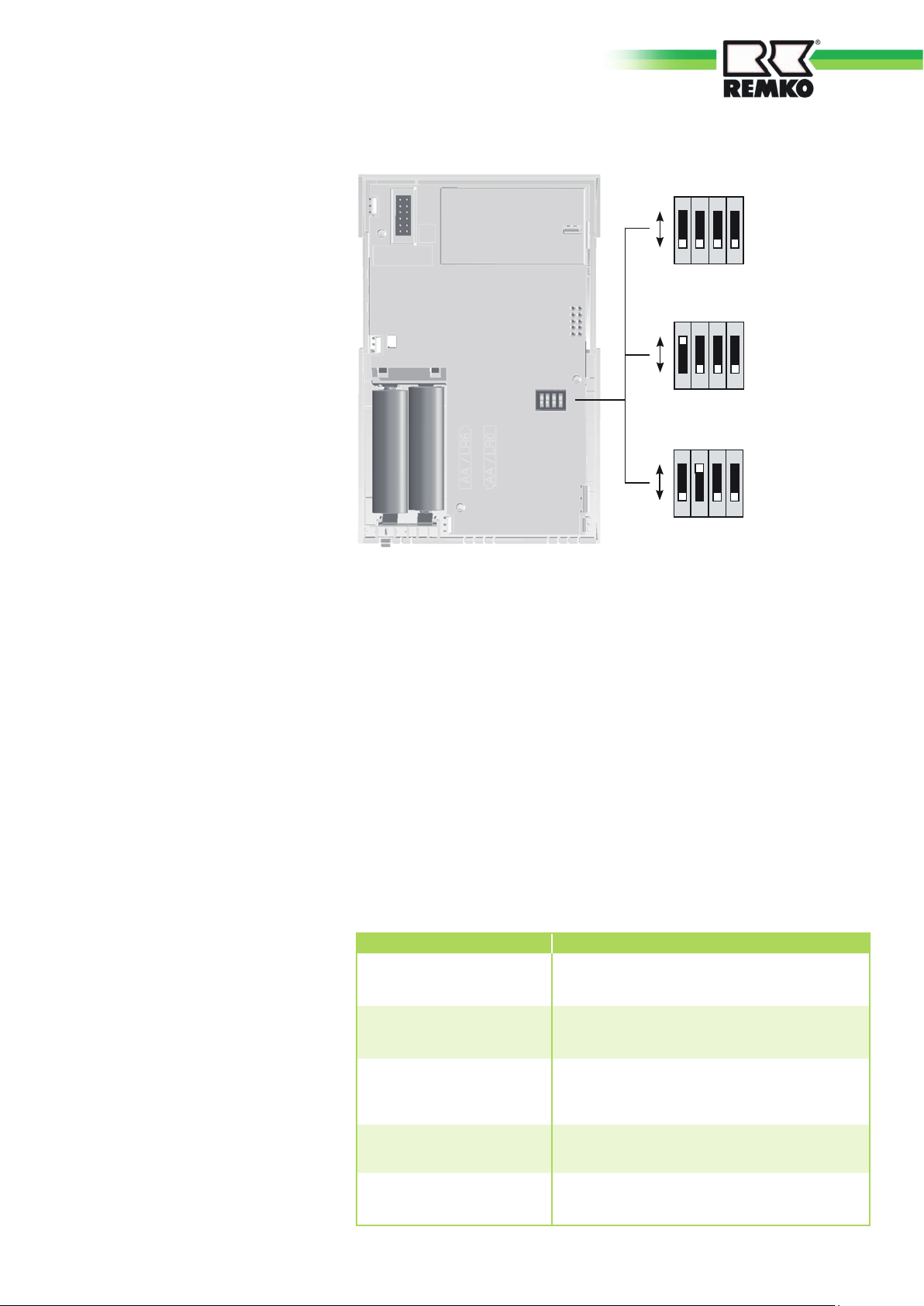
Installation
Assembly
1. Secure the base to the wall.
ON
Channel setting 0
2. Setting the channel:
On the back of the wireless
remote control the channel
(0 – 2) must be set, while the
batteries are removed.
The setting must match that on
the HF-CAN.
3. Insert the batteries.
4. Snap the top of the controller
into place; to do so, position/
hook in the left-hand side so it
is centred and then pivot the
right-hand side down onto the
base using light pressure and
engage.
The dimensions of the unit are: 147mm x 97mm x 32mm
The mounting holes are suited for fitting to a switch box
A cable feedthrough is provided.
Commissioning
1 2
3
Dip 1-4
Dip 1-4
Dip 1-4
4
Channel setting 1
3
4
Channel setting 2
3
4
OFF
ON
OFF
ON
OFF
1 2
1 2
Disassembly
1. Lift the upper section off
the base on the right-hand side.
2. Unscrew the base from the wall.
The following steps must be
followed when commissioning:
1. Read this manual carefully
before commissioning.
2. Fit the controller (see chapter
“Installation”).
3. Wait until the message
Installation appears on the
display.
4. Start installation with the F-key
[4] = OK.
5. Set the value with the rotary
knob.
6. Press F-key [4] = OK => Saves
the value and moves to the
next value.
7. Continue until installation is
complete => Standard display
8. Set the Programme switch to
the desired operating mode,
e.g. Automatic 1 (see chapter
“Operation/Mode selection”)
BUS CODE (heating circuit number):
The heating circuits are numbered sequentially, starting with “01”. Heating circuit numbers must not be assigned more than once. Please only
use “00” for replacement controllers (see chapter “System bus”).
For information on registration, see chapter “Specialist menu”.
In the Commissioning menu, all values must be entered successively –
without interruption!
Values Required action
English Set language, then “OK”
Set time
Set date
Bus code
(see chapter System bus)
Registration Registration on the HF-CAN
1. Hour then “==>”
2. Minute then “OK”
1. Year then “<==”
2. Month then “<==”
3. Day then “OK”
Enter number for heating circuit:
00-15 => Default 01, then “OK”
27
Page 28

REMKO WIRELESS REMOTE CONTROL
FOR MULTITALENT HEAT PUMP MANAGER
Changing the battery
If the battery symbol shown below
displays 0%, the battery should be
changed within the next week.
100% 50% 0%
System bus
Heating system bus system
This controller can be expanded
modularly by connecting additional
modules to the integrated bus.
As supplied, the system can be
used to control the following
components of a heating system
1-8 Heating appliances (
modulating or switching)
1-15 Mixed weather-based
heating circuits
0-15 Room controller (digital
or analogue)
1 Solar energy system (2
collectors, 2 tanks)
1 Solid fuel boiler
The different components are
simply connected to the system
bus. The modules register with the
system automatically and search
for their communication partners
using the set bus code (heating
circuit number or boiler number).
Bus code
On mixer controllers and control
panels
The bus code (00-15; parameter
in the Specialist menu) is a means
of numbering the system's heating
circuits. Each control module and
each mixer module contains the
number of the associated heating
circuit, in the form of a bus code.
- Heating circuit numbers
(00-15) must not be assigned
twice.
- Heating circuit numbers 00 and
01 must not both be used
at the same time.
- The heating circuits are
numbered sequentially, starting
with “01”.
- Please only use heating
circuit number 00 for replacement
controllers, if “00” has been
used in the replaced controller.
Preassigned numbers
Heating circuit 1 01
NOTE
After setting all bus codes,
the heating system must
be fully powered down once.
28
Page 29

Technical data
Radio frequency MHz 868,0 - 868,6
Max. transmission power mW 4
Supply voltage 2x LR6 alkaline cell
Power consumption mA 0,15
Protection category in accordance with EN 60529 IP 40
Protection class according to EN 60730 III
Permitted ambient temperature during operation °C 0 - 50
Permitted ambient temperature in storage °C -20 - +60
Permitted humidity, non-condensing R.H. in % 95
The range is approx. 300 m in
the open air, i.e. the range if
there is visual contact between
the transmitter and receiver.
However, in real-world conditions,
there are walls, ceilings, etc.
between the transmitter and the
receiver, which reduces range
accordingly.
NOTE
Although the product only
emits relatively weak radio
signals, these can still cause
malfunctions to life-sustaining
systems (e.g. medical devices).
NOTE
Radio signals from unrelated
devices, e.g. cordless
telephones or mobile phones
can impair the transmission
of the wireless remote control
and the receiver.
29
Page 30

Notes
Page 31

Notes
Page 32
REMKO INTERNATIONAL
... and also right in your neighbourhood!
Take advantage of our experience and advice
REMKO GmbH & Co. KG
Klima- und Wärmetechnik
Im Seelenkamp 12 D-32791 Lage
Postfach 1827 D-32777 Lage
Telephone +49 5232 6 06-0
Fax +49 5232 606-2 60
e-mail info@remko.de
Website www.remko.de
Hotline
Air conditioning and
heating technology
+49 5232 606-0
Export
+49 5232 606-130
Consultation
Thanks to intensive training,
our consultants are always
completely up-to-date when
it comes to technical expertise.
This has given us the reputation
of being more than just an
excellent, reliable supplier:
REMKO, a partner
that helps you find solutions to
your problems.
Sales
REMKO offers not just a well
established sales network both
nationally and internationally, but
also has exceptionally highlyqualified sales specialists.
REMKO field staff are more than
just sales representatives: above
all, they must act as advisers to
our customers in air conditioning
and heating technology.
Customer Service
Our units operate precisely and
reliably. However, in the event
of a fault REMKO customer
service is quickly on the scene.
Our comprehensive network
of experienced dealers always
guarantees quick and
reliable service.
We reserve the right to make technical changes and provide no warranty as to the accuracy of this data!
 Loading...