

REMKO LWM Series, LWM 80, LWM 110, LWM 150, LWM 110 Duo Operating And Installation Instructions
...
Operating and
installation instructions
REMKO LWM series
Monobloc heat pumps
Air/water system for heating and cooling
LWM 80, LWM 110, LWM 150, LWM 110 Duo, LWM 150 Duo
Instructions for Technicians
0205-2019-07 Edition 1, en_GB
Read the instructions prior to performing any task!

R454B
Refrigerant
Read these operating instructions carefully before commissioning / using this device!
These instructions are an integral part of the system and must
always be kept near or on the device.
Subject to modifications; No liability accepted for errors or misprints!
Translation of the original

Table of contents
1 Safety and usage instructions............................................................................................................. 4
1.1 General safety notes....................................................................................................................... 4
1.2 Identification of notes...................................................................................................................... 4
1.3 Personnel qualifications.................................................................................................................. 4
1.4 Dangers of failure to observe the safety notes................................................................................ 4
1.5 Safety-conscious working............................................................................................................... 5
1.6 Safety notes for the operator........................................................................................................... 5
1.7 Safety notes for installation, maintenance and inspection.............................................................. 5
1.8 Unauthorised modification and changes......................................................................................... 5
1.9 Intended use................................................................................................................................... 5
1.10 Warranty........................................................................................................................................ 6
1.11 Transport and packaging............................................................................................................... 6
1.12 Environmental protection and recycling........................................................................................ 6
2 Technical data........................................................................................................................................ 7
2.1 Unit data.......................................................................................................................................... 7
2.2 Product data.................................................................................................................................. 11
2.3 Unit dimensions of indoor units..................................................................................................... 13
2.4 Diagram, cooling cycle.................................................................................................................. 15
2.5 Heat pump usable limits in monovalent operation........................................................................ 16
2.6 Pump characteristics and circulation pump pressure losses........................................................ 16
2.7 Total sound power level................................................................................................................. 18
2.8 Characteristic curves..................................................................................................................... 21
3 Unit description................................................................................................................................... 31
4
Assembly............................................................................................................................................. 35
4.1 System layout................................................................................................................................ 35
4.2 General installation notes.............................................................................................................. 36
4.3 Set-up and assembly of the heat pump........................................................................................ 37
5 Hydraulic connection.......................................................................................................................... 42
6 Emergency-heat operation................................................................................................................. 46
7 Cooling with room temperature/humidity probe.............................................................................. 47
8 Water treatment................................................................................................................................... 48
9 Commissioning the refrigeration system......................................................................................... 50
10 Electrical wiring................................................................................................................................... 52
11 Before commissioning....................................................................................................................... 52
12 Commissioning................................................................................................................................... 53
13 Care and maintenance........................................................................................................................ 54
14 Temporary shutdown.......................................................................................................................... 54
15 Troubleshooting and customer service............................................................................................ 55
16 General view of unit and spare parts................................................................................................ 56
16.1 Exploded view of the unit LWM 80-150....................................................................................... 56
16.2 Spare parts LWM 80-150............................................................................................................ 57
17 General terms...................................................................................................................................... 59
18 Index..................................................................................................................................................... 61
3

REMKO LWM series
1 Safety and
usage instructions
1.1 General safety notes
Carefully read the operating manual before commissioning the units or their components for the
first time. It provides useful tips and notes such as
hazard warnings to prevent injury and material
damage. Failure to follow
manual can endanger persons, the environment
and the equipment itself or its components and will
void any claims for liability.
Store this manual and the information required for
the operation of this system (e.g. refrigerant datasheet) in the vicinity of the unit.
The refrigerant used in the system is flammable. If
applicable, observe the local safety conditions.
the directions in this
DANGER!
This combination of symbol and signal word
warns of a situation in which there is immediate
danger
cause serious injury.
This combination of symbol and signal word
warns of a potentially hazardous situation,
which if not avoided may be fatal or cause
serious injury
, which if not avoided may be fatal or
WARNING!
.
Warning of inflammable substances!
Identification of notes
1.2
This section provides an overview of all important
safety aspects for proper protection of people and
safe and fault-free operation.The instructions and
safety notes contained within this manual must be
observed in order to prevent accidents, personal
injury and material damage.
Notes attached directly to the units must be
observed in their entirety and be kept in a fully
legible condition.
Safety notes in this manual are indicated by symbols. Safety notes are introduced with signal words
which help to highlight the magnitude of the danger
in question.
CAUTION!
This combination of symbol and signal word
warns of a potentially hazardous situation,
which if not avoided may cause injury or material and environmental damage.
NOTICE!
This combination of symbol and signal word
warns of a potentially hazardous situation,
which if not avoided may cause material and
environmental damage.
This symbol highlights useful tips and recommendations as well as information for efficient
and fault-free operation.
DANGER!
Contact with live parts poses an immediate
danger of death due to electric shock. Damage
to the insulation or individual components may
pose a danger of death.
1.3 Personnel qualifications
Personnel responsible for commissioning, operation, maintenance, inspection and installation must
be able to demonstrate that they hold a qualification which proves their ability to undertake the
work.
Dangers of failure to observe
1.4
the safety notes
Failure to observe the safety notes may pose a risk
to people, the environment and the units. Failure to
observe the safety notes may void any claims for
damages.
4

In particular, failure to observe the safety notes
may pose the following risks:
n The failure of important unit functions.
n The failure of prescribed methods of mainte-
nance and repair
n Danger to people on account of electrical and
mechanical effects.
.
1.5 Safety-conscious working
The safety notes contained in this manual, the
existing national regulations concerning accident
prevention as well as any internal company
working, operating and safety regulations must be
observed.
Safety notes for the operator
1.6
The operational safety of the units and components is only assured providing they are used as
intended and in a fully assembled state.
n The units and components may only be set up,
installed and maintained by qualified personnel.
n Protective covers (grille) over moving parts
must not be removed from units that are in
operation.
n Do not operate units or components with
obvious defects or signs of damage.
n Contact with certain unit parts or components
may lead to burns or injury
n The units and components must not be
exposed to any mechanical load, extreme
levels of humidity or extreme temperature.
n Spaces in which refrigerant can leak sufficient
to load and vent. Otherwise there is danger of
suffocation.
n All housing parts and device openings, e.g. air
inlets and outlets, must be free from foreign
objects, fluids or gases.
n The units must be inspected by a service tech-
nician at least once annually. Visual inspections and cleaning may be performed by the
operator when the units are disconnected from
the mains.
.
1.7 Safety notes for installation, maintenance and inspection
n Appropriate hazard prevention measures must
be taken to prevent risks to people when performing installation, repair
cleaning work on the units.
n The setup, connection and operation of the
units and its components must be undertaken
in accordance with the usage and operating
conditions stipulated in this manual and comply
with all applicable regional regulations.
, maintenance or
n Regional regulations and laws as well as the
ater Ecology Act (WHG) must be observed.
W
n Only install and store the units in rooms larger
than 4 m2. With a failure to comply, leaks may
result in the room filling with a flammable mixture! The minimum room size of 4 m2 required
for installation and storage pertains to the basic
fill quantity of the unit. This varies according to
the installation type and total fill quantity of the
system. The calculation must take place in
accordance with valid DIN standards. Make
sure that the installation site is suitable for safe
unit operation.
n The electrical power supply should be adapted
to the requirements of the units.
n Units may only be mounted at the points pro-
vided for this purpose at the factory. The units
may only be secured or mounted on stable
structures, walls or floors.
n Mobile units must be set up securely on suit-
able surfaces and in an upright position. Stationary units must be permanently installed for
operation.
n The units and components should not be oper-
ated in areas where there is an increased risk
of damage. Observe the minimum clearances.
n The units and components must be kept at an
adequate distance from flammable, explosive,
combustible, abrasive and dirty areas or
atmospheres.
n Safety devices may not be modified or
bypassed.
1.8 Unauthorised modification and changes
Modifications or changes to units and components
are not permitted and may cause malfunctions.
Safety devices may not be modified or bypassed.
Original replacement parts and accessories
authorised by the manufactured ensure safety
use of other parts may invalidate liability for
resulting consequences.
. The
1.9 Intended use
Depending on the model, the equipment and the
additional fittings with which it is equipped is only
intended to be used as an air-conditioner for the
purpose of cooling or heating the air in an
enclosed room.
Any different or additional use shall be classed as
non-intended use. The manufacturer/supplier
assumes no liability for damages arising from such
use. The user bears the sole risk in such cases.
Intended use also includes working in accordance
with the operating and installation instructions and
complying with the maintenance requirements.
5

REMKO LWM series
Under no circumstances should the threshold
values specified in the technical data be exceeded.
1.10
For warranty claims to be considered, it is essential
that the ordering party or its representative complete and return the "certificate of warranty" to
REMKO GmbH & Co. KG at the time when the
units are purchased and commissioned.
The warranty conditions are detailed in the "General business and delivery conditions". Furthermore, only the parties to a contract can conclude
special agreements beyond these conditions. In
this case, contact your contractual partner in the
first instance.
Warranty
1.11 Transport and packaging
The devices are supplied in a sturdy shipping container. Please check the equipment immediately
upon delivery and note any damage or missing
parts on the delivery and inform the shipper and
your contractual partner. For later complaints can
not be guaranteed.
1.12 Environmental protection and recycling
Disposal of packaging
All products are packed for transport in environmentally friendly materials. Make a valuable contribution to reducing waste and sustaining raw materials. Only dispose of packaging at approved
collection points.
Disposal of equipment and components
Only recyclable materials are used in the manufacture of the devices and components. Help protect
the environment by ensuring that the devices or
components (for example batteries) are not disposed in household waste, but only in accordance
with local regulations and in an environmentally
safe manner, e.g. using certified firms and recycling specialists or at collection points.
WARNING!
Plastic films and bags etc. are dangerous
toys for children!
Why:
- Leave packaging material are not around.
- Packaging material may not be accessible to
children!
6

2 Technical data
2.1 Unit data
Series LWM 80 LWM 110 LWM 150
Function Heating or Cooling
System Air/water
Heat pump manager Smart Control Touch
Drinking water tank enamelled optional
Auxiliary heater installed/rated output kW optional 7.5
Domestic hot-water heating (changeover valve)
Connection oil/gas boiler changeover
valve
Heating capacity min./max. kW 0.6-8.0 2.0-10.7 3.0-14.5
Heating capacity/COP
with A12/W35 kW/COP 7.5/5.65 9.18/5.57 11.0/5.58
with A7/W35 kW/COP 6.25/5.10 8.04/5.02 10.28/5.03
with A2/W35 kW/COP 4.33/4.09 6.35/4.04 8.33/4.11
with A-7/W35 kW/COP 3.82/3.55 5.57/3.42 7.85/3.57
with A-15/W35 kW/COP 2.6/2.95 4.47/2.82 6.5/2.97
with A7/W45 kW/COP 6.05/3.96 7.87/3.88 10.09/3.89
with A-7/W45 kW/COP 3.73/2.96 5.51/2.83 7.76/2.98
with A7/W55 kW/COP 5.68/3.20 7.50/3.12 9.72/3.13
with A-7/W55 kW/COP 3.64/2.49 5.42/2.36 7.67/2.51
with A10/W35 kW/COP 6.80/5.43 8.55/5.31 10.60/5.32
Cooling capacity min./max. kW 1.1-8.9 3.3-11.9 5.5-14.0
Cooling capacity/EER
1)
2)
optional
optional
with A35/W7 kW/EER 4.90/2.81 7.63/2.73 12.20/2.65
with A35/W18 kW/EER 5.70/3.61 8.24/3.71 12.77/3.81
with A27/W18 kW/EER 5.80/3.92 10.71/4.00 18.20/4.11
Usable limits, heating °C -23 to +37
Service limits, cooling °C +15 to +45
Inlet temperature, heating water, max. °C 65
Min. inlet temperature for cooling °C 7
Heat pump power supply V/Ph/Hz 230/1~/50 400/3~/50
Electrical heating element power supply
(Smart Serv)
Control board power supply V/Ph/Hz 230/1~/50
7
V/Ph/Hz 400/3~/50

REMKO LWM series
Series LWM 80 LWM 110 LWM 150
Heater for anti-freeze protection power
supply (optional)
V/Ph/Hz 230/1~/50
Max. current consumption per phase A 5.8 4.7 6.6
Rated current consumption for A7/W35 A 5.30 2.57 3.27
Rated power consumption for A7/W35 kW 1.22 1.60 2.04
Rated power consumption for A2/W35 kW 1.06 1.57 2.03
Max. power consumption kW 1.3 3.2 4.5
Power factor at A7/W35 (cosφ) -- 0.9
Customer-provided electrical protection
Refrigerant
A slow-
acting
16 3 x 20
R454B
3)
Refrigerant, basic capacity kg 1.3 1.4 1.6
Medium flow rate
water(according to EN 1451
1, at ∆t 5 K)
m3/h
1.1 1.4 1.6
Pressure loss (heating system), outdoor kPa 80 70 60
Max. airflow volume
m3/h
3000 3500 4000
Max. operating pressure, water bar 3
Hydraulic connection,
inlet/return flow (flat-sealing)
Recommended diameter for copper
piping to be used by the customer
Inches (DN) 1 1/4 (32)
mm 28
Max. sound power level in acc. with
dB(A) 54 56 58
DIN EN 12102:2008-09 and ISO 9614-2
Sound pressure level, LpA
4)
dB(A) 32 34 36
Tonality dB(A) 0
Sound power level/sound pressure
level
night operations/lowering mode
dB(A) 47/25 49/27 51/29
Dimensions (height/width/depth) mm 1600 x 1000 x 850
Enclosure class -- IP X4
Weight kg 200 220
1)
COP = coef
ficient of performance in accordance with EN 14511, VDE tested, rated compressor frequency
60 Hz
2)
EER = energy efficiency ratio in accordance with EN 14511, rated compressor frequency 60 Hz
3)
Contains greenhouse gas according to Kyoto protocol, GWP 466
4)
Distance 5 m, VDE tested, A7/W55, with half-spherical propagation
Information provided without guarantee! We reserve the right to make technical changes within the framework of technical advancement.
8

Series LWM 110 Duo LWM 150 Duo
Function Heating or Cooling
System Air/water
Heat pump manager Smart Control Touch
Drinking water tank enamelled optional
Auxiliary heater/rated output per heat pump kW 7.5
Domestic hot-water heating (changeover valve) optional
Connection oil/gas boiler optional
Heating capacity min./max. kW 2.0-21.4 3.0-29.0
Heating capacity/COP
1)
with A12/W35 kW/COP 18.36/5.57 22.00/5.58
with A7/W35 kW/COP 16.08/5.02 20.56/5.03
with A2/W35 kW/COP 12.70/4.04 16.66/4.11
with A-7/W35 kW/COP 11.14/3.42 15.70/3.57
with A-15/W35 kW/COP 8.94/2.82 13.00/2.97
with A7/W45 kW/COP 15.74/3.88 20.18/3.89
with A-7/W45 kW/COP 11.02/2.83 15.52/2.98
with A7/W55 kW/COP 15.00/3.12 19.44/3.13
with A-7/W55 kW/COP 10.84/2.36 15.34/2.51
with A10/W35 kW/COP 17.10/5.31 21.20/5.32
Cooling capacity min./max. kW 3.3-23.8 5.5-28.0
Cooling capacity/EER
2)
with A35/W7 kW/EER 15.26/2.65 24.40/2.65
with A35/W18 kW/EER 16.48/3.71 25.54/3.81
with A27/W18 kW/EER 21.42/4.00 36.08/4.11
Usable limits, heating °C -23 to +37
Service limits, cooling °C +15 to +45
Inlet temperature, heating water, max. °C 65
Min. inlet temperature for cooling °C 7
Power supply per heat pump V/Ph/Hz 400/3~/50
Power supply per electrical heating element
V/Ph/Hz 400/3~/50
(Smart Serv)
Power supply per control board V/Ph/Hz 230/1~/50
Power supply per heater for anti-freeze protection
(optional)
V/Ph/Hz 230/1~/50
Max. current consumption per phase and heat pump A 4.7 6.6
Rated current consumption for A7/W35 per heat pump A 2.57 3.27
9

REMKO LWM series
Series LWM 110 Duo LWM 150 Duo
Rated power consumption for A7/W35 kW 1.60 2.04
Rated power consumption for A2/W35 per heat pump kW 1.57 2.03
Max. power consumption per heat pump kW 3.2 4.5
Power factor at A7/W35 (cosφ) per heat pump -- 0.9
Fuse protection provided by the customer per heat pump
Refrigerant
Max. refrigerant basic filling quantity per heat pump kg 1.4 1.6
Medium flow rate water(according to EN 14511, at ∆t 5 K)
per heat pump
Outdoor pressure loss (heating system) per heat pump kPa 70 60
Max. airflow volume per heat pump
Max. water operating pressure per heat pump bar 3
Hydraulic connection inlet/return flow, flat-sealing
per heat pump
Copper collector line diameter
to be used by the customer per heat pump
Max. sound power level in acc. with
DIN EN 12102:2008-09 and ISO 9614-2
Sound pressure level LpA 4)per heat pump
Tonality dB(A) 0
Sound power level/sound pressure
levelnight operations/lowering mode
per heat pump
per heat pump
A slow-
acting
m3/h
m3/h
Inches (DN) 1 1/4 (32)
mm 42
dB(A) 56 58
dB(A) 34 36
dB(A) 49/27 51/29
1.4 1.6
2x3500 2x4000
3 x 20
R454B
3)
Dimensions per heat pump (height/width/depth) mm 1600 x 1000 x 850
Enclosure class -- IP X4
Weight per heat pump kg 200 220
1)
COP = coef
60 Hz
2)
EER = energy efficiency ratio in accordance with EN 14511, rated compressor frequency 60 Hz
3)
Contains greenhouse gas according to Kyoto protocol, GWP 466
4)
Distance 5 m, VDE tested, A7/W55, with half-spherical propagation
Information provided without guarantee! We reserve the right to make technical changes within the framework of technical advancement.
ficient of performance in accordance with EN 14511, VDE tested, rated compressor frequency
10

2.2 Product data
Average condition
1)
Series LWM 80 LWM 110 LWM 150
Energy efficiency ratio, heating 35°C/55°C A++/A++
Nominal heating power P rated kW 5 7 10
Room heating energy efficiency hs 35°C/55°C
% 161/136 161/142 164/138
Contribution to the seasonal room heating
% 4
energy ef
Yearly energy consumption QHE 35°C/ 55°C
Sound power level L
Warmer condition
ficiency of the REMKO Smart-Control
4)
A
W
2)
2629/3173 3395/3797 4588/5780
dB(A) 56 58 60
Series LWM 80 LWM 110 LWM 150
Energy efficiency ratio, heating 35°C/55°C A++/A++
Nominal heating power P rated kW 4 6 8
Room heating energy efficiency hs 35°C/55°C
Yearly energy consumption QHE 35°C/ 55°C
4)
% 182/160 187/167 169/164
1326/1379 1668/1638 2550/2537
Colder condition
3)
Series LWM 80 LWM 110 LWM 150
Energy efficiency ratio, heating 35°C/55°C A++/A++
Nominal heating power P rated kW 7 9 13
Room heating energy efficiency hs 35°C/55°C
Yearly energy consumption QHE 35°C/ 55°C
1)
verage condition = Moderate temperature periods
A
2)
Warmer condition = Warm temperature periods
3)
Colder condition = Cold temperature periods
4)
The specified value is based on results from standard testing.
4)
% 147/114 145/122 148/120
4158/6135 5485/7278 7319/10700
The actual consumption depends on the use and location of the unit
11

REMKO LWM series
Average condition
1)
Series LWM 110 Duo LWM 150 Duo
Energy efficiency ratio, heating 35°C/55°C A++/A++
Nominal heating power P rated kW 14 20
Room heating energy efficiency hs 35°C/55°C
% 161/142 164/138
Contribution to the seasonal room heating
% 4
energy ef
Yearly energy consumption QHE 35°C/ 55°C
Sound power level L
Warmer condition
ficiency of the REMKO Smart-Control
4)
per heat pump
A
W
2)
6790/7594 9176/11560
dB(A) 58 60
Series LWM 110 Duo LWM 150 Duo
Energy efficiency ratio, heating 35°C/55°C A++/A++
Nominal heating power P rated kW 12 16
Room heating energy efficiency hs 35°C/55°C
Yearly energy consumption QHE 35°C/ 55°C
4)
% 187/167 169/164
3336/3276 5100/5074
Colder condition
3)
Series LWM 110 Duo LWM 150 Duo
Energy efficiency ratio, heating 35°C/55°C A++/A++
Nominal heating power P rated kW 18 26
Room heating energy efficiency hs 35°C/55°C
Yearly energy consumption QHE 35°C/ 55°C
1)
verage condition = Moderate temperature periods
A
2)
Warmer condition = Warm temperature periods
3)
Colder condition = Cold temperature periods
4)
The specified value is based on results from standard testing.
4)
% 145/122 148/120
10970/14556 14638/21400
The actual consumption depends on the use and location of the unit
12

2.3 Unit dimensions of indoor units
40+20
840
934
1600
845
985
40
180
110 140
180
130
734
700
A
C
B
Unit dimensions
Fig. 1: Unit dimensions (all dimensions in mm)
A: Front view
B: Bird´s eye view
13
C: Side view

845
985
40
180
110 140
180
130
2
1
4
3
2
3
A
B
a
b
b
a
0
31
71
111
76
181
221
199
153
0
57
106
166
113
262
377
REMKO LWM series
Designations of the pipe connections
Fig. 2: Designations of the pipe connections
A: Rear view
B: Bird´s eye view
1: Condensate drain
2: Inlet heat pump 1 1/4"
3: Return flow heat pump 1 1/4"
4: Cable inlets
a: Air inlet
b: Air outlet
14

2.4 Diagram, cooling cycle
2
1
4
3
8
9
14
13
15
16
17
18 19
20
6
5
7
12
EEV
10
11
Fig. 3: Diagram, cooling cycle
1: Refrigerant dryer
2: Refrigerant inspection glass
3: Electr. expansion valve
4: Finned heat exchanger air suction probe
5: Finned heat exchanger fan
6: Finned heat exchanger air outlet probe
7: Refrigerant probe suction-side
8: Low pressure switch
9: Compressor
10: Refrigerant collector
11: Hot gas probe/Suction gas probe
12: High pressure switch 45 bar
13: 4-way changeover valve
14: Safety valve
15: Water outlet probe/Heat pump inlet
16: Smart Serv 7.5 kW
17: Manual bleeder valve
18: Water outlet probe/Heat pump return flow
19: Cap valve
20: Circulation pump
15

A
B
-23°C; 45°C
-7°C; 65°C
37°C; 60°C
37°C; 35°C
-23°C; 24°C
20
25
30
35
40
45
50
55
60
65
70
-30 -20 -10 0 10 20 30 40
REMKO LWM series
2.5 Heat pump usable limits in monovalent operation
Fig. 4: Usable limits LWM
A: Outside temperature [°C] B: Heating water inlet temperature [°C]
Outside temperature [°C] -23 -23 -7 37 37
Inlet temperature [°C] 24 45 65 60 35
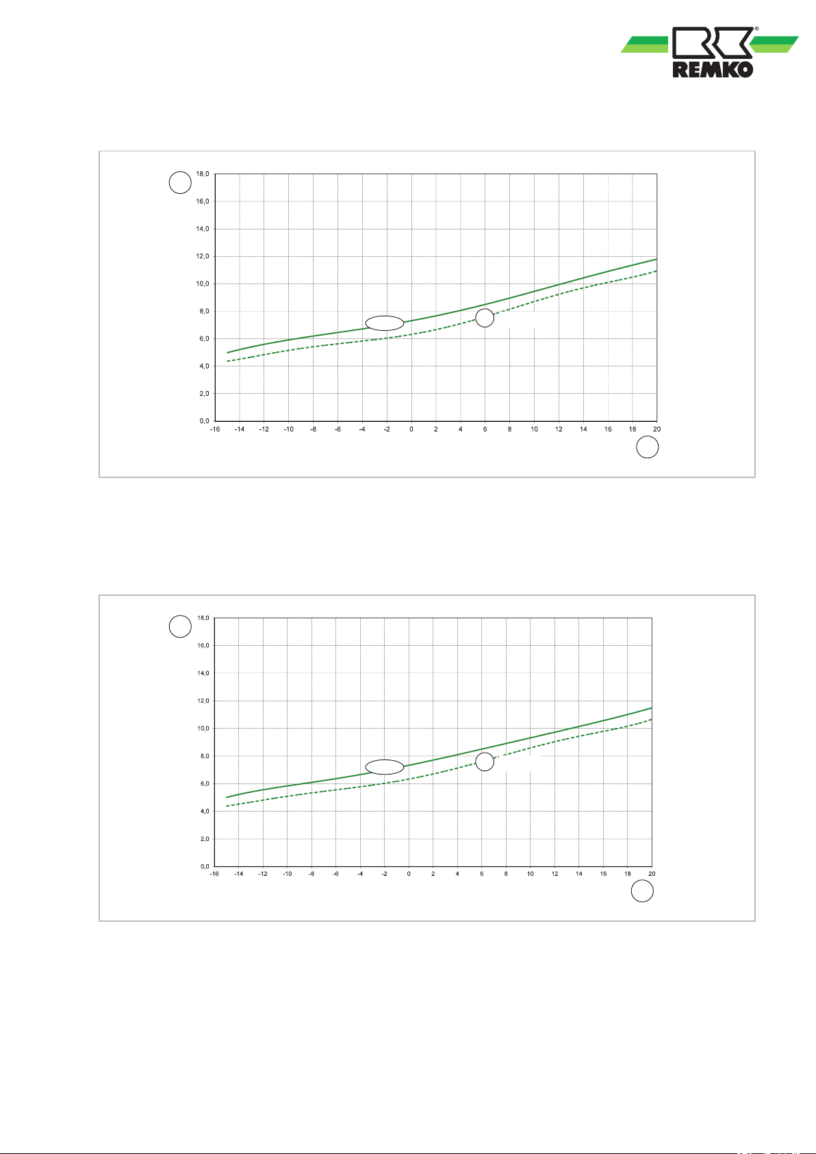
2.6 Pump characteristics and circulation pump pressure losses
Fig. 5: Capacity range of the UPMXL 25-125
p: Power consumption [kPa]
H: Delivery height [m]
External control via analogue-In PWM signal. The tolerances of each curve are in acc. with EN 1151-1:2006
Q:
Requirement [l/s or m3/h ]
16

Stage Effective power consumption [W] Current consumption [A] Motor protection
min. 7 0.07 blocking current
resistant
max. 136 1.03 blocking current
resistant
Technical data
Pump type Grundfos UPMXL 25-125
Installation length mm 180
Connecting threads Inche
R 1 / G 1 1/2
s
Internally controlled via PP/CP/CC -
Control signal
Digital bidirectional
low voltage PWM signal
l
Power supply voltage+ 10/- 15 % 50 Hz V 1 x 230 V
The heating system must be dimensioned in such a way that at least the nominal heating water flow rate can
be achieved with the residual head of the circulation pump.
Residual head LWM
Series LWM 80 LWM 110 LWM 150
Nomin. 1) heating water throughput per heat pump m3/h
Residual head 2) per heat pump
3-way changeover valve pressure loss
3)
kPa 80 70 60
kPa 7 8 10
1.1 1.4 1.6
Spread K 5 5 5
1)
Nominal volume flow rates according to DIN EN 1451
1, for efficient and safe operation do not fall below the
nominal value.
2)
Residual head with pumps according to accessories (without pressure loss of the 3-way changeover valve)
3)
REMKO changeover valve DN 25
The pipe dimensions from the heat pump to the on-site hydraulic connection must be designed according to
the design medium flow rate.
The minimum diameter is DN 25.
Duo collector
Heat pump pipe length to on-site hydraulic system 1-13 m 13-20 m
Smooth pipe with inside diameter DN 25 DN 32
*)
The copper pipe of the Duo variant collector line must have an inside diameter of at least 42 mm.
line
DN 40
*)
In the case of metal composite pipes, the higher individual resistances of the fittings mean that a design with
residual head must be carried out.
17

0,0
10,0
20,0
30,0
40,0
50,0
60,0
100 125 160 200 250 315 400 500 630 800 1000 1250 1600 2000 2500 3150 4000 5000 6300 8000 10000
A
B
2
1
3
REMKO LWM series
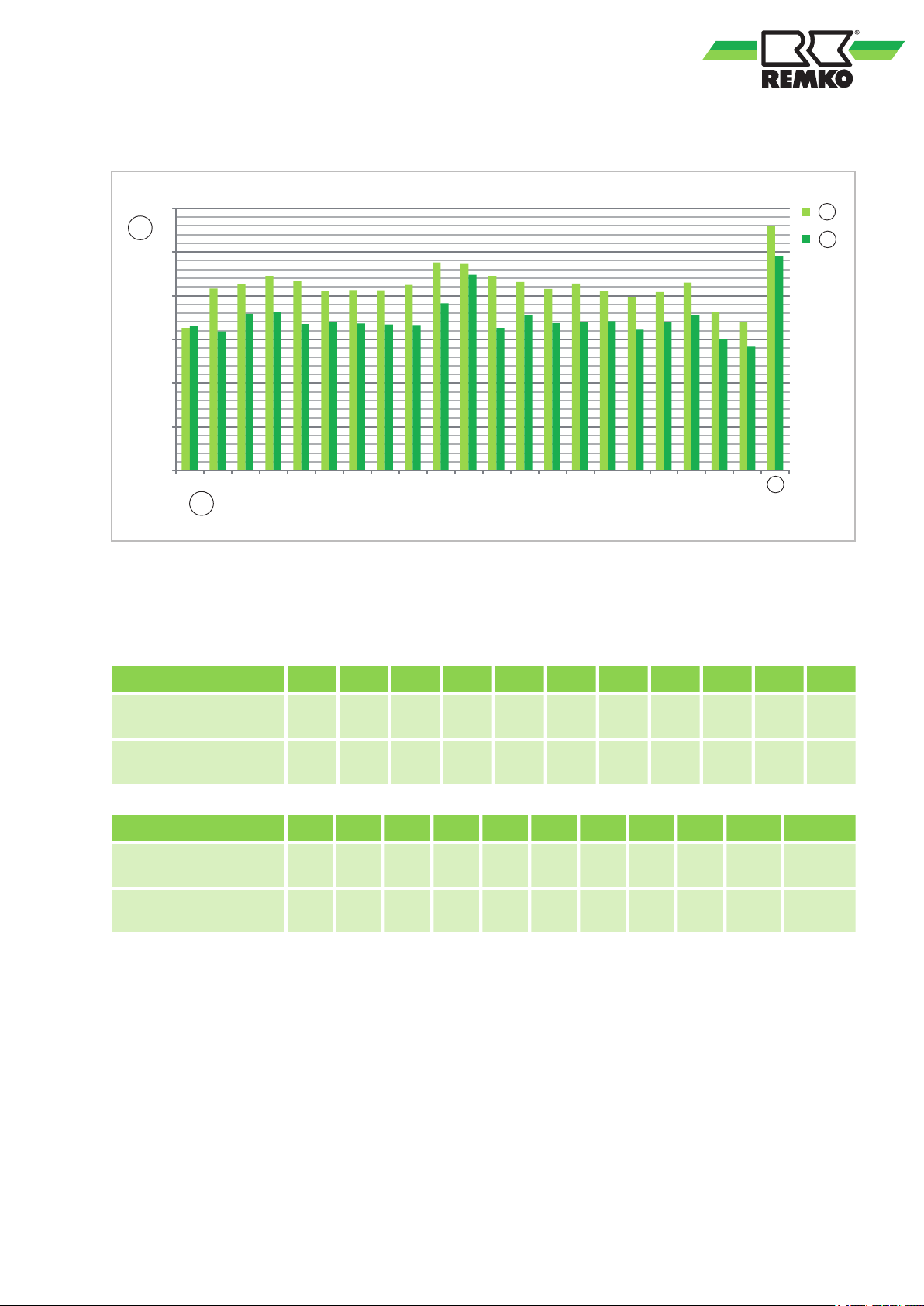
2.7 Total sound power level
LWM 80
Fig. 6:
T
otal sound power level L
A: Sound power level LwAre 1pW [dB(A)]
B: Frequency [Hz]
P
2: Night mode 60% A7/W55
3: A total [dB(A)]
1: Nominal/max. A7/W55
Middle frequency [Hz] 100 125 160 200 250 315 400 500 630 800 1000
Nominal/max.
A7/W55 [dBA]
Night mode 60%
A7/W55 [dBA]
30.6 39.6 40.6 42.4 41.3 38.9 39.2 39.2 40.4 45.5 45.4
30.9 29.8 33.8 34.1 31.5 31.9 31.6 31.4 31.2 36.2 42.7
Middle frequency [Hz] 1250 1600 2000 2500 3150 4000 5000 6300 8000 10000 A total
Nominal/max.
A7/W55 [dBA]
Night mode 60%
A7/W55 [dBA]
The sound power conforms to accuracy class 2.
The standard deviation of the aforementioned A-valued sound power levels amounts to 1.5 dB.
42.4 41.1 39.6 40.7 38.9 37.9 38.8 41.0 34.1 32.0 53.9
30.6 33.4 31.6 31.9 32.1 30.2 31.8 33.4 28.0 26.3 47.1
18
LWM 110/LWM 110 Duo
A
B
2
1
3
0,0
10,0
20,0
30,0
40,0
50,0
60,0
100 125 160 200 250 315 400 500 630 800 10 00 1250 1600 2000 2500 3150 4000 5000 6300 8000 10000
Fig. 7:
T
otal sound power level L
A: Sound power level LwAre 1pW [dB(A)]
B: Frequency [Hz]
P
2: Night mode 60% A7/W55
3: A total [dB(A)]
1: Nominal/max. A7/W55
Middle frequency [Hz] 100 125 160 200 250 315 400 500 630 800 1000
Nominal/max.
A7/W55 [dBA]
Night mode 60%
A7/W55 [dBA]
32.6 41.6 42.6 44.4 43.3 40.9 41.2 41.2 42.4 47.5 47.4
32.9 31.8 35.8 36.1 33.5 33.9 33.6 33.4 33.2 38.2 44.7
Middle frequency [Hz] 1250 1600 2000 2500 3150 4000 5000 6300 8000 10000 A total
Nominal/max.
A7/W55 [dBA]
Night mode 60%
A7/W55 [dBA]
44.4 43.1 41.5 42.7 40.9 39.6 40.8 43.0 36.1 34.0 55.9
32.6 35.4 33.6 33.9 34.1 32.2 33.8 35.4 30.0 28.3 49.1
The sound power conforms to accuracy class 2.
The standard deviation of the aforementioned A-valued sound power levels amounts to 1.5 dB.
19

A
B
3
0,0
10,0
20,0
30,0
40,0
50,0
60,0
70,0
100 125 160 200 250 31 5 40 0 500 630 800 1000 1250 1600 2000 2500 3150 4000 5000 6300 80 00 10000
2
1
REMKO LWM series
LWM 150/LWM 150 Duo
Fig. 8:
T
otal sound power level L
A: Sound power level LwAre 1pW [dB(A)]
B: Frequency [Hz]
P
2: Night mode 60% A7/W55
3: A total [dB(A)]
1: Nominal/max. A7/W55
Middle frequency [Hz] 100 125 160 200 250 315 400 500 630 800 1000
Nominal/max.
A7/W55 [dBA]
Night mode 60%
A7/W55 [dBA]
34.6 43.6 44.6 46.4 45.2 42.9 43.2 43.2 44.4 49.5 49.4
34.9 33.8 37.8 38.1 35.3 35.9 35.6 35.4 35.2 36.2 46.7
Middle frequency [Hz] 1250 1600 2000 2500 3150 4000 5000 6300 8000 10000 A total
Nominal/max.
A7/W55 [dBA]
Night mode 60%
A7/W55 [dBA]
46.4 45.1 43.5 44.7 42.9 41.6 42.8 45.0 38.1 36.0 57.9
34.6 37.4 35.6 35.9 36.1 34.2 35.8 37.4 32.0 30.8 51.1
The sound power conforms to accuracy class 2.
The standard deviation of the aforementioned A-valued sound power levels amounts to 1.5 dB.
20

2.8 Characteristic curves
60 Hz
A
B
n-max
C
60 Hz
A
B
n-max
C
Heating capacity LWM 80 at inlet temperature of 35°C
Fig. 9: Heating capacity at inlet temperature of 35 °C
A: Outside temperature [°C]
B: Heating capacity/total thermal load [kW]
Heating capacity LWM 80 at inlet temperature of 45 °C
C: Rated frequency [Hz]
Fig. 10: Heating capacity at inlet temperature of 45 °C
A: Outside temperature [°C]
B: Heating capacity/total thermal load [kW]
21
C: Rated frequency [Hz]

60 Hz
A
B
n-max
C
A
35° C
45° C
55° C
D
E
E
E
REMKO LWM series
Heating capacity LWM 80 at inlet temperature of 55 °C
Fig. 11: Heating capacity at inlet temperature of 55 °C
A: Outside temperature [°C]
B: Heating capacity/total thermal load [kW]
COP LWM 80 at inlet temperature 35 °C, 45 °C and 55 °C
C: Rated frequency [Hz]
Fig. 12: COP at inlet temperature 35°C, 45°C and 55°C
A: Outside temperature [°C]
D: COP [-]
E: Inlet temperature [°C]
22
Heating capacity LWM 110 at inlet temperature of 35 °C
60 Hz
A
B
n-max
C
A
B
n-max
60 Hz
C
Fig. 13: Heating capacity at inlet temperature of 35 °C
A: Outside temperature [°C]
B: Heating capacity/total thermal load [kW]
Heating capacity LWM 110 at inlet temperature of 45 °C
C: Rated frequency [Hz]
Fig. 14: Heating capacity at inlet temperature of 45 °C
A: Outside temperature [°C]
B: Heating capacity/total thermal load [kW]
23
C: Rated frequency [Hz]

A
B
n-max
60 Hz
C
A
35° C
45° C
55° C
D
E
E
E
REMKO LWM series
Heating capacity LWM 110 at inlet temperature of 55 °C
Fig. 15: Heating capacity at inlet temperature of 55 °C
A: Outside temperature [°C]
B: Heating capacity/total thermal load [kW]
COP LWM 110 at inlet temperature 35 °C, 45 °C and 55 °C
C: Rated frequency [Hz]
Fig. 16: COP at inlet temperature 35°C, 45°C and 55°C
A: Outside temperature [°C]
D: COP [-]
E: Inlet temperature [°C]
24

Heating capacity LWM 150 at inlet temperature of 35 °C
A
B
n-max
60 Hz
C
A
B
n-max
60 Hz
C
Fig. 17: Heating capacity at inlet temperature of 35 °C
A: Outside temperature [°C]
B: Heating capacity/total thermal load [kW]
Heating capacity LWM 150 at inlet temperature of 45 °C
C: Rated frequency [Hz]
Fig. 18: Heating capacity at inlet temperature of 45 °C
A: Outside temperature [°C]
B: Heating capacity/total thermal load [kW]
25
C: Rated frequency [Hz]

A
B
n-max
60 Hz
C
A
35° C
45° C
55° C
D
E
E
E
REMKO LWM series
Heating capacity LWM 150 at inlet temperature of 55 °C
Fig. 19: Heating capacity at inlet temperature of 55 °C
A: Outside temperature [°C]
B: Heating capacity/total thermal load [kW]
COP LWM 150 at inlet temperature 35 °C, 45 °C and 55 °C
C: Rated frequency [Hz]
Fig. 20: COP at inlet temperature 35°C, 45°C and 55°C
A: Outside temperature [°C]
D: COP [-]
E: Inlet temperature [°C]
26

Heating capacity LWM 110 Duo at inlet temperature of 35 °C
60 Hz
A
B
n-max
C
A
B
n-max
60 Hz
C
Fig. 21: Heating capacity at inlet temperature of 35 °C
A: Outside temperature [°C]
B: Heating capacity/total thermal load [kW]
Heating capacity LWM 110 Duo at inlet temperature of 45 °C
C: Rated frequency [Hz]
Fig. 22: Heating capacity at inlet temperature of 45 °C
A: Outside temperature [°C]
B: Heating capacity/total thermal load [kW]
27
C: Rated frequency [Hz]

A
B
n-max
60 Hz
C
A
35° C
45° C
55° C
D
E
E
E
REMKO LWM series
Heating capacity LWM 110 Duo at inlet temperature of 55 °C
Fig. 23: Heating capacity at inlet temperature of 55 °C
A: Outside temperature [°C]
B: Heating capacity/total thermal load [kW]
COP LWM 110 Duo at inlet temperature 35 °C, 45 °C and 55 °C
C: Rated frequency [Hz]
Fig. 24: COP at inlet temperature 35°C, 45°C and 55°C
A: Outside temperature [°C]
D: COP [-]
E: Inlet temperature [°C]
28

Heating capacity LWM 150 Duo at inlet temperature of 35 °C
A
B
n-max
60 Hz
C
A
B
n-max
60 Hz
C
Fig. 25: Heating capacity at inlet temperature of 35 °C
A: Outside temperature [°C]
B: Heating capacity/total thermal load [kW]
Heating capacity LWM 150 Duo at inlet temperature of 45 °C
C: Rated frequency [Hz]
Fig. 26: Heating capacity at inlet temperature of 45 °C
A: Outside temperature [°C]
B: Heating capacity/total thermal load [kW]
29
C: Rated frequency [Hz]

A
B
n-max
60 Hz
C
A
35° C
45° C
55° C
D
E
E
E
REMKO LWM series
Heating capacity LWM 150 Duo at inlet temperature of 55 °C
Fig. 27: Heating capacity at inlet temperature of 55 °C
A: Outside temperature [°C]
B: Heating capacity/total thermal load [kW]
COP LWM 150 Duo at inlet temperature 35 °C, 45 °C and 55 °C
C: Rated frequency [Hz]
Fig. 28: COP at inlet temperature 35°C, 45°C and 55°C
A: Outside temperature [°C]
D: COP [-]
E: Inlet temperature [°C]
30

1
3
4
2
3 Unit description
Description
The LWM series is a monobloc heat pump in which
refrigeration components are installed in a hermetically sealed refrigeration circuit. In addition, a
highly ef
and an electric volume flow monitor are integrated.
Furthermore, an optional electric Smart-Serv auxiliary heater can be installed to realise monoenergetic operation. The Smart-Serv can also be used
for screed drying, hygiene functions or emergency
heat-operation.
If the on-site pressure loss does not exceed the
maximum available, a heating buffer tank can be
dispensed with. If necessary, only a drinking water
storage tank and changeover valve should then be
installed.
A district heating pipe is recommended as the
water-bearing pipe from the heat pump into the
house. This can be supplied as an option. The
Smart-Control Touch controller is supplied in an
attractively designed housing for wall mounting or
as a built-in controller in an indoor unit with a
storage tank. The touch display can optionally be
installed in a double flush-mounted or double surface-mounted box. With the Smart-Control Touch,
three heating cycles can be activated, two of which
act as a mixing cycle. Further functions such as
solar thermal, second heat generator as bivalent
system, cooling, external heating cycle pumps can
be controlled as standard. A combination with a PV
system to increase its own power requirement is
integrated as standard.
ficient speed-controlled circulation pump
Function of the heat pump
A heat pump is a unit which makes use of a
working medium to absorb ambient heat under low
temperatures and transports this heat to a place
where it can be of use for heating purposes. Heat
pumps work according to the same principles as a
refrigerator. The difference is that heat, the “byproduct” of the refrigerator, is the goal of the heat
pump.
The main components of the cooling circuit consist
of an evaporator, a compressor, a condenser and
an expansion valve. In a finned evaporator, the
refrigerant evaporates both because of lower pressure and because of lower heat-source temperatures through absorption of energy from the environment. In the compressor, the refrigerant is
brought to a higher pressure and temperature by
the application of electrical energy. Next, the hot
refrigerant gas reaches the condenser, a plate heat
exchanger. Here the heat gas condenses, transferring heat to the heating system. The liquefied
refrigerant then expands and cools in a flow regulator, the expansion valve. Then the refrigerant
flows into the evaporator once more and the cycle
is complete.
Smart-Control Touch is used for regulation, and it
assures the independent operation of all safety
devices. The water circulation system consists of a
circulation pump, plate heat exchangers, dirt traps,
safety valve, a manometer, filling and drain valves,
a flow switch and a service water storage tank.
A 3-way changeover valve, overflow protection
valve, additional probes and storage systems are
available as accessories.
Fig. 29: Functional diagram heating
1: Condensing
2: Liquefying
3: Decompression
4: Evaporation
31

REMKO LWM series
Layout
A precise calculation of the building’s heating load
according to EN 12831 is required for the design
and dimensioning of a heating system. However
approximate requirements can be determined
based on the year of construction and the type of
Ä
building. This table
approximate specific heating load for a few types
of building. The required heating system output
can be calculated by multiplying the area to be
heated with the given values.
For a precise calculation, various factors must be
considered. The transmission-heat requirement,
the infiltration heat-loss and an allowance for water
heating comprise the total heating capacity which
the heating system must provide.
The total area of the floor surfaces, exterior wall
windows, doors and roofing is required in order to
determine the transmission heat requirement. In
addition, information about the materials used in
the building is required, as well as about the different thermal transmission coefficients (known as
the K value). Also required are the room temperature and the standard outside temperature, that is,
the lowest outside temperature on average that will
occur during the year. The equation for determining the thermal transmission requirement is
Q=A x U x (tR-tA) and must be calculated for all
enclosed room floor areas.
The infiltration heat requirement takes into consideration how often the heated room air is
exchanged for cold external air. The room volume
“V”, the air exchange frequency “n” and the specific heat capacity “c” of the air is also required in
addition to the room temperature and average low
temperature. The equation is: Q = V x n x c (tR-tA)
An approximate addition for the preparation of
domestic water per person amounts in acc. with
VDI 2067: 0.2 kW.
on page 32 provides an
,
Design example
By way of a design example, a residential home
with a living area of 150 m2 and a heating requirement of approx. 40 W/m2 was selected. A total of
five persons live in the house. The heat load
amount to 6.0 kW
ance of 0.2 kW results in a required heating
capacity of 7.0 kW. Depending on the power company, an additional charge must then be made in
order to factor in any service time-out periods that
may apply. The rating and determination of the
heat pump’s balance-point temperature derives
graphically from the heat pump’s inlet temperature
specific heat-output diagram (in this example 35 °C
for underfloor heating). Next, the heat load for the
standard outdoor temperature (the lowest temperature of the year locally) and the heat threshold are
marked on the graph. The outside-temperaturedependent heating requirement, (Fig. 30) simplified
here as a straight-line relationship between heatload and the start of the heating season, is
recorded in the graph of heat-load curves. The
intersection of the two straight lines with the rated
heat-load curve is plotted on the X axis, where the
balance-point temperature is read (in this example
approx. -3 °C). The minimum performance of the
2nd heat source is the difference between heat
load and the heat pump’s maximum heating
capacity on these days (in this example, the
required power required to cover peak load
requirements is approx. 3 kW).
. Adding a drinking water allow-
Building type
Passive energy house 10
Low-energy house built in 2002 40
According to energy conservation order regarding heat insulation
1995
Modern building constructed around 1984 80
Partially renovated old building constructed pre-1977 100
Non-renovated old building constructed pre-1977 200
Specific heating capacity in W/m
60
2
32

14.0
Outside temperature [°C]
Heating capacity/totalheat requirement [kW]
Bivalence point - 3 °C
Standard outside temperature
Heating load in accordance with DIN EN 12831
Rated frequency
n-max
Total thermal load
Bivalence point determination at inlet temperature 35 °C
Fig. 30: Heating performance diagram of the heat pump LWM
Monobloc heat pump
The REMKO inverter heat pump is connected to
the house via water-carrying pipes. The water-carrying pipes must be laid to be frost proof. If this is
not possible from a structural point of view
, other
frost protection measures must be implemented,
e.g. glycol, trace heating, etc.
REMKO inverter technology
The heat pump's compressor is equipped with are
equipped with a speed control system, as needed.
The power control on conventional heat pumps
provides only two states, either “ON” (full output) or
“OFF” (no output). The heat pump turns on below
a specified temperature and turns off when this
temperature is reached. Heat regulation in the
REMKO monobloc heat pump is modulated to the
actual need and is adjusted to suit actual needs.
The electronics system has an integrated frequency-converter which serves to modify the compressor speed and the speed of the fan as
required. The compressor works at a higher speed
when under full load than under partial load. The
lower speeds ensure a longer operational lifetime
for the components, improved coefficient of performance and lower noise. Lower speeds also
result in lower energy consumption (electricity) and
longer service life. I.e.: Monobloc heat-pumps will
run practically throughout the heating season. In
all, the highest efficiency possible.
33

1/3
When it is switched on, the inverter only requires
one-third of the time of conventional systems
Time
Minimal temperature fluctuations
mean energy savings
Conventional
Inverter
Temperature
10 12 14 16 18 20 22 24 26 28 30
uncomfortably
humid
comfortable
still comfortable
uncomfortably
dry
Relative humidity in %
Room air temperature in °C
REMKO LWM series
Fig. 31: Modern inverter technology
Cooling mode
Because of circuit reversal, cooling is also possible. In cooling mode, the components of the
refrigeration circuit are used to produce cold water
with which heat can be extracted from a building.
This can be accomplished with dynamic cooling or
passive cooling.
With dynamic cooling the refrigerating capacity is
actively transferred to the indoor air. This is achieved by means of water-based fan convectors. In
doing so, it is desirable that the inlet temperatures
are under the dew point, in order to transfer a
higher refrigerating capacity and to dehumidify the
indoor air.
Passive cooling refers to the absorption of heat
via cooled floors, walls or ceiling surfaces. In doing
so, water-carrying pipes make the structural sections into thermally effective heat exchangers. In
order to achieve this, the refrigerant temperature
has to lie above the dew point, in order to avoid the
formation of condensation. Dew-point monitoring is
required for this purpose.
We recommend dynamic cooling with fan convectors, in order to achieve increased cooling capacity
and in order to dehumidify the air on muggy
summer days. You will find corresponding devices
in the KWD, KWK and WLT-S series on our website: “www.remko.de”. The advantage here is that
dew point monitoring is not required.
The comfort zone in the illustration below shows
which values for temperature and humidity are
considered comfortable for people. This range
should ideally be met when heating or air-conditioning buildings.
Fig. 32: Comfort zone
34

4 Assembly
A
C
B
21 3
Außenfühler
B1
C
D
21 3 54
B2
E
A1 A2
6
4.1 System layout
System layout for heat pump assembly LWM 300 IM Stuttgart
A: Outdoor unit
B: Indoor unit with storage tank
C: External probe
System layout for heat pump assembly LWM Duo Mannheim
1: Unmixed cycle
2: Cold water
3: Hot water
A1/A2: Heat pump 1 and 2
B1: Hot water storage tank
B2: Buffer tank
C: External probe
D: Boiler/wall heating unit (optional)
E: Smart Control Touch
35
1: Hot water
2: Cold water
3: Unmixed cycle
4: Mixed cycle
5: Mixed cycle
6: Collector line (min. DN 40)

2
1
3
REMKO LWM series
4.2 General installation notes
DANGER!
All electrical installation work must be done by
an electrician.
WARNING!
All electric lines are in accordance VDE regulations to dimension and to lay
DANGER!
The connection of refrigerant pipes and the
handling of refrigerant may be only be carried
out by qualified personnel (competence category I).
n These instructions are to be observed when
installing the heat pump.
n The unit should be delivered as near as pos-
sible to the site of installation in its original
packaging in order to avoid transport damage.
n The unit is to be checked for visible signs of
transport damage. Possible faults are to be
reported immediately to the contractual partner
and the haulage company
n Suitable sites for installation are to be selected
with regard to machinery noise and the set-up
process.
n It is recommended to place the heat pump as
close as possible to the building to be heated,
observing the minimum distances.
n Establish all electrical wiring in accordance
with the relevant DIN and VDE standards.
n The electrical power cables must always be
fastened to the electrical terminals in the
proper manner. Otherwise there is a risk of
damage.
n Ensure that no water-carrying pipes pass
through living or sleeping areas.
.
.
Wall opening
n A wall opening of approx. 200 mm diameter
and 10 mm incline from the inside to the outside must be created.
o prevent damage, the interior of the wall
n T
opening should be padded or, for example,
lined with PVC pipe (see figure).
n After installation has been completed, use a
suitable sealing compound to close off the wall
opening provided by the customer, taking
account of fire protection regulations and local
conditions.
n District heating pipelines are recommended
(see accessories).
Fig. 33: Wall opening
1: Inlet/return flow, heat pump
2: Power supply, heat pump
3: Smart-Control control cable (shielded)
36

4.3 Set-up and assembly
1
20 cm
1
of the heat pump
Set-up site
n The unit may be attached only to a load-
bearing structure or wall. Ensure that the unit is
installed only vertically
should be well ventilated.
n To minimise noise, install floor consoles with
vibration dampers and a considerable distance
from acoustically-reflective walls to minimise
noise.
n The minimum clearances specified on the next
page should be maintained when carrying out
the installation. These minimum distances
serve to ensure unrestricted air inlet and outlet.
The air that has discharged may not be drawn
in again. Take the performance data of the
units into account. Additionally, there must be
adequate space available for installation, maintenance and repair.
n If the unit is erected in an area of strong winds,
then it must be protected against them and
additional stabilisation is recommended. This
can be realised for example with wire ropes or
other constructions (Fig. 34). The snow line is
to be observed during installation (Fig. 35).
n REMKO recommends always placing the unit
on vibration dampers. Vibration dampers prevent the transmission of vibrations through the
floor or walls.
n If there is insufficient space under the device
for the lines, then the pre-cut recesses can be
removed from the rear enclosure-panel and the
pipes guided through these openings.
n During installation, add about 20 cm to the
expected snow depth to guarantee unimpeded
intake and exhaust of outdoor air year round
(Fig. 35).
n The installation site of the outdoor unit should
be agreed together with the operator primarily
so that ’non-concerning levels of operating
noise’ are achieved, rather than in respect
of ’short distances’.
. The installation site
NOTICE!
The site for the unit must be selected so that
machinery noise that occurs disturbs neither the
residents nor the facility operator
TA-noise specifications as well as the table containing the drawings relating to sound pressure
levels!
The quick calculator of the "Bundesverbandes
Wärmepumpe e.V." (German Federal Association of Heat Pumps) can be used for theoretical
calculations (www.waermepumpe.de/schallrechner/).
Fig. 35: Protection against snow
1: Snow
. Observe the
Fig. 34: Protection against wind
1: Wind
37

REMKO LWM series
Assessment level in accordance
with T
Point of emissions
Daytime in
dB(A)
Industrial areas 70 70
Commercial areas 65 50
Core areas, village areas and mixed zones 60 45
General residential areas and small housing estates 55 40
Exclusively residential areas 50 35
Spa areas, hospitals and mental institutions 45 35
Isolated noise peaks of short duration may not exceed 30 dB(A) during the day and 20 dB(A) at night.
A noise
Night-time in
dB(A)
Definition of the Danger Area
WARNING!
Access to the unit is only permitted for authorised and trained persons. If unauthorised persons can approach the danger areas, these
areas must be identified with corresponding
signs, barriers, etc.
n The external danger area surrounds the unit up
to a distance of 2 m, measured in all directions
from the unit housing.
n The external danger area on-site can dif
a result of the setup. The specialist company
performing the installation work bears the
responsibility for this.
n The internal danger area is located inside the
machine and can only be reached with the use
of an appropriate tool. Access is prohibited for
unauthorised persons!
fer as
38

1
2
43
>= 250
>= 2000
>= 250
>= 1000
>= 1000
>= 900
>= 250
2
3
>= 600 >= 600 >= 600 >= 600
>= 250
>= 2000
>= 2000 >= 3000>= 600 >= 250
1
Minimum distances during construction
of a heat pump
Minimum distances during construction
of multiple heat pumps
Fig. 36: Minimum distances during construction of
a heat pump in mm
1: Next to a wall, air outlet open to the front, flow
restriction behind
2: Next to a wall, air outlet toward the wall, flow
restriction to the front
3: In a niche, air outlet open to the front, flow
restriction behind and on both sides
4: Next to a covered wall, air outlet open to the
front, flow restrictions behind and above
Fig. 37: Minimum distances during construction of
multiple heat pumps in mm
1: Next to a wall, air outlet toward the wall, flow
restriction to the front
2: In a niche, air outlet open to the front, flow
restriction behind and on both sides
3: Between two walls, air outlet toward the wall
and in the direction of other devices, open
sides: flow restriction front and rear
39

2
3
7
5
1
9 1010
44
8 8
6
A
D
C
4
4
EB
B
1
9
5
5
REMKO LWM series
Condensate drainage connection and safe
drainage - strip foundation
Fig. 38: Condensate drainage, seepage of condensate and strip foundation (cross-section)
1: Heat pump (air outlet)
2: Vibration dampers
3: Floor bracket (accessory)
4: Reinforced strip foundation, frost free
5: Gravel layer for seepage
6: Protective tube for lines and
electrical connecting line
(temperature resistant up to at least 80 °C)
7: Drainage channel
8: Frost line
9: Drainage pipe
10: Soil
NOTICE!
When installing an L
minimum distances must be observed and an
air short circuit must be prevented.
WM-Duo heat pump, the
Fig. 39: Dimensions for the strip foundation (bird's
eye view)
1: Heat pump
4: Reinforced strip foundation, frost free
5: Gravel layer for seepage
9: Drainage pipe
dimensioning the strip foundation
(all dimensions in mm)
Dime
nsion LWM 80 LWM 110 LWM 150
A 1000 1000 1000
B 200 200 200
C 840 840 840
D 700 700 700
E 600 600 600
NOTICE!
Anti-freeze protection
In the case of heat pump systems, in which
frost-free conditions are not assured, a
drainage facility should be provided. If control
and heating circulation pump are ready for
operation, the anti-freeze protection function of
the controller works. The system must be emptied when the heat pump is shut down or there
is a power failure. For heat pump systems in
which a power failure cannot be detected (e.g.
holiday home), the heating circuit must be operated with a suitable anti-freeze protection.
40

Condensate drainage connection
If the temperature falls below the dewpoint on the
finned evaporator
heating operation.
The condensate water must be drained off frostfree via a condensation pipe with a diameter of at
least 50 mm.
n The condensate drainage line must be pro-
vided by the customer and have an incline of at
least 2 %. If necessary
proof insulation.
n When operating the unit at outside tempera-
tures below 4 °C, ensure the condensate
drainage line is laid to protect it against frost. If
necessary, the lower part of the housing and
condensate tray is to be kept frost free in order
to ensure permanent draining of the condensate. If necessary, fit a pipe heater.
n If the substrate is permeable to water, it is suffi-
cient to lead the pipe vertically at least 90 cm
deep into the ground.
n In the case of condensate drainage in drains or
into the sewer system, the installation must be
frost-free and with an incline.
n The condensate may only be discharged into
the sewer system via a funnel siphon, which
must be accessible at all times.
Regional laws must be observed.
n Following installation, check that the conden-
sate run off is unobstructed and ensure that the
line is durably leak tight.
, condensation occurs during the
, fit vapour-diffusion-
Heater for anti-freeze protection
The heater for anti-freeze protection is used to
control the temperature of the interior space of the
hydraulic unit. This ensures that in the event of a
fault, the last step in the freezing of the medium
and thus defects due to frost can be prevented. A
temperature of >+3 °C is established through recirculated air operation. It is essential that a separate
UPS is used for the power supply
Safe drainage in the event of leakages
NOTICE!
Local regulations or environmental laws, for
example the German W
(WHG), can require suitable precautions to protect against uncontrolled draining in case of
leakage to provide for safe disposal of escaping
refrigerator oil or hazardous media.
NOTICE!
With the connection of an external drain line to
the oil separator
, it must be kept frost-free.
ater Resource Law
.
Pipe heater
A pipe heater can be mounted on water-carrying
pipes to ensure frost protection in the pipes.
Install a pipe heater if there is a risk of frost.
When installing on the mounting bracket or on a
foundation, we recommend the installation of a
pipe heater if the condensate drain or the inlet/
return flow heat pipes cannot be laid in a frost-free
manner or if they are heavily exposed to weather
conditions.
The pipe heater must be connected to a separate power supply (UPS).
41

2
1
3
REMKO LWM series
5 Hydraulic connection
A separate interpretation of nominal flow rate
must be made for every system (see technical
data).
n W
e recommend installing a buffer tank as a
hydraulic compensator for hydraulic isolation of
the heating cycle. Hydraulic isolation is
required when:
- different inlet temperatures need to be achieved, e.g. underfloor heating/radiators
- the pressure drop in the heating distribution
system is greater than stated in the technical
data
- the use of other heat generators, e.g. combustible burner for solid fuel, solar or bivalent
(dual-fuel) systems.
n Perform a pipe-network calculation before
installing the heat pump. After installing the
heat pump, it is necessary to perform a
hydraulic balancing of the heating circuit.
n Protect underfloor heating systems against
excessively high inlet temperatures.
n Do not reduce pipe diameters for the inlet and
return flow connections to the heat pump
before connecting a buffer tank.
n Plan for air bleed valves and drain-off taps at
appropriate places.
n Flush the system’s entire pipe network before
connecting the heat pump.
n One or, where necessary, several expansion
vessels must be designed for the entire
hydraulic system.
n The system pressure of the entire pipe network
is to be matched to the hydraulic system and
must be checked when the heat pump is
turned off. Also update the static-pressure form
supplied with the heat pump.
n As delivered, the safety assembly consists of a
pressure gauge, a bleeding valve and a safety
valve. This must be installed by the customer
in the hydraulic system.
n During installation, the minimum cross-sections
of the collector line must be 42 mm or larger.
Fig. 40: Safety assembly
1: Pressure gauge
2: Automatic bleeding valve
3: Safety valve
n All exposed metallic surfaces must be addition-
ally insulated.
n Cooling mode via the heating circuit requires a
complete vapour density insulation along the
entire length of the pipework.
n All outgoing heating cycles, including the con-
nections for water heating, are to be secured
against the ingress of circulating water by
means of check valves.
n Before being placed in service, the system
must be thoroughly flushed. Conduct a seal
test and perform a thorough bleeding of the
entire system - repeatedly
with DIN standards.
Actual schemas for hydraulic integration can be
found on the internet at www
, if necessary, in acc.
.remko.de
42

A
C
B
21 3
Hydraulic diagram for heat pump assembly LWM Stuttgart
Functions: Heating/cooling and hot water, operating mode: monoenergetic
This hydraulic cycle diagram serves solely to assist in planning activities;
the customer-provided hydraulic system on site must be planned and installed by the installation contractor!
Fig. 41: Example hydraulic diagram
A: Heat pump
B: Indoor unit LWM 300 IM
C: External probe
LWM compact heat pump models are ideal for use in new construction, where the heat pump is the sole heat
generator
Smart Control.
The indoor unit consists of an enamelled 300 l drinking water storage tank of the EWS series. In addition, a
3-way changeover valve and an electric bypass valve are installed.
The Smart-Control installed in the indoor unit switches all electrical components. Due to the pre-installed
components, considerable assembly time is saved.
The highly efficient primary pump in the outdoor unit [A] can be used as a heating cycle pump and its speed
is regulated according to requirements. There is a pressure drop present on site (see technical data). If the
pressure losses on site exceed this, a separate storage tank, e.g. REMKO KPS, must be used as a hydraulic
compensator. Then a REMKO heating cycle group unmixed, type HGU, and two mixed heating cycle groups,
type HGM, are available. Moreover, the hot water and cold water supply connections are all connected to the
indoor unit on the top.
A circulation line can optionally be connected to the storage tank.
So that the heat pump can efficiently and smoothly supply the heating water system directly (without buffer
tank), the following basic prerequisites must be fulfilled:
n The heating system must be able to be operated with an inlet temperature
n The maximum pressure drop in the heating system must not be exceeded
n A minimum water flow volume of 20 l/KW must be assured. If this is not possible, then a valve must be
n The pipe cross sections of the lines from the heat pump to the heating manifolds shall not be reduced
n The min. water volume of 5 l/kW cooling capacity with active cooling must be observed
. In an emergency, an electr. auxiliary heater (mono-energetic variant) can be switched on by the
installed at a suitable location (last heating manifold)
1: Unmixed cycle
2: Cold water
3: Hot water
(e.g. only floor heating)
43

Außenfühler
B1
C
D
21 3 54
B2
E
A1 A2
6
REMKO LWM series
Hydraulic diagram for heat pump assembly LWM Duo Mannheim
Functions: Heating/cooling and hot water, operating mode: monoenergetic
This hydraulic cycle diagram serves solely to assist in planning activities;
the customer-provided hydraulic system on site must be planned and installed by the installation contractor!
A1: Heat pump 1
A2: Heat pump 2
B1: Hot water storage tank
B2: Buffer tank
C: External probe
D: Boiler/wall heating unit (optional)
E: Smart Control Touch
The LWM compact heat pump models are ideal for use in new or in existing buildings, where the heat pump
is the sole heat generator
The Smart-Control regulation switches all electrical components.
The highly efficient primary pump inside the heat pump is used as the circulation pump. The combination
buffer tank consists of an enamelled 300 l hot water tank [B1] and a 100 l vapour diffusion-tight buffer tank
[B2] which is integrated into the system. The buffer tank is the hydraulic compensator if the pressure losses
of the heating system are too high (see “Technical data”).
n An air short circuit of the external units must be prevented
n The pressure loss available on site from both heat pumps must not be exceeded.
n The collector line of the heat pumps must be at least DN 40
n The hydraulic connection of the individual heat pumps must be at least DN 25
n The pipe cross sections of the lines from the heat pump to the connection to the storage tank shall not be
reduced
n The min. water volume with active cooling must be observed.
n The hydraulic connection of the L
. An additional heat generator can be installed to cover peak loads.
WM-Duo variant must always be made via a suitable buffer tank
1: Hot water
2: Cold water
3: Unmixed cycle
4: Mixed cycle
5: Mixed cycle
6: Collector line (min. DN 50)
44

KWS 300
A
B1
C
B2
E
21 3 54
D
Hydraulic diagram for heat pump assembly LWM Mannheim
Functions: Heating/cooling and hot water, operating mode: monoenergetic
This hydraulic cycle diagram serves solely to assist in planning activities;
the customer-provided hydraulic system on site must be planned and installed by the installation contractor!
Fig. 42: Example hydraulic diagram
A: Heat pump
B1: Hot water storage tank
B2: Buffer tank
C: External probe
D: Boiler/wall heating unit (optional)
E: Smart Control Touch
The LWM compact heat pump models are ideal for use in new or in existing buildings, where the heat pump
is the sole heat generator
The Smart-Control regulation switches all electrical components.
The highly efficient primary pump inside the heat pump is used as the circulation pump. The combination
buffer tank consists of an enamelled 300 l hot water tank [B1] and a 100 l vapour diffusion-tight buffer tank
[B2] which is integrated into the system. The buffer tank is the hydraulic compensator if the pressure losses
of the heating system are too high (see “Technical data”).
n The heating cycles connected must be hydraulically balanced.
n The pressure drop between heat pump and storage tank must not be exceeded.
n A minimum water flow volume of 20 l/KW must be assured.
n The pipe cross sections of the lines from the heat pump to the storage tank may not be reduced.
n The min. water volume of 5 l/kW cooling capacity with active cooling must be observed.
. An additional heat generator can be installed to cover peak loads.
1: Hot water
2: Cold water
3: Unmixed cycle
4: Mixed cycle
5: Mixed cycle
45

REMKO LWM series
6 Emergency-heat
operation
If the compressor fails, you can start emergencyheat operation as follows:
1. Activation of emergency-heat operation is
only possible in the expert level of the SmartControl regulation. T
"Expert" level on the basic display.
2. After activating the expert level by touching
the REMKO logo, a password is required (the
password is: "0321").
3. After confirmation, +/- symbols are displayed
at the bottom. The password can be set by
touching the +/- symbols. After the entry
confirm with "OK".
The REMKO default password for the expert
level is "0321". If this password has not
already been changed, the expert level is
enabled after entering this password.
After the expert level has been enabled, various parameter levels are visible.
4. Select the "Settings" level by touching the
"Settings" icon.
5. After selecting the "Settings" level, select the
"Basic settings" parameter
6. The "System configuration" parameter
appears in the "Basic settings" level. Select
this icon by touching it.
7. After selecting the "System configuration"
level, select the "Heat pump" parameter
8. Then deactivate the heat pump in the “Heat
pump” level by touching the “activated” icon
and changing the operating mode setting
from “activated” to “deactivated”.
The heat pump is now deactivated.
o do this, select the
,
.
.
With deactivation of the heat pump, the second
heat generator
iary heater or a condensing unit installed in the
system is active.
NOTICE!
If the heat pump is switched of
gering the fuse, the water must be drained
manually to prevent freezing.
, e.g. the REMKO Smart-Serv auxil-
f, e.g. by trig-
46

7 Cooling with room tem-
perature/humidity probe
Description of the Cooling Installation
Cooling via the mixed heating cycle
(surface heating cycle )
If the heat pump is to be used for cooling, then this
must be possible via the heating cycle. The
hydraulic connection is identical to the connection
for the heating cycle. If the mixed cycle is used for
heating or cooling, it will be connected as shown in
Fig. 42 and Fig. 41. The probes S12 and S1
measure the inlet and return flow temperatures, if a
heating/cooling buffer is used. Dew-point monitoring is required for this.
Dew point regulation via room temperature/
humidity probe
If cooling via the surface heating is also required in
summer, this can only be activated in conjunction
with the Smart-Control Touch and the appropriate
room temperature/humidity probe. Only with the
use of the REMKO room temperature/humidity
probe it is possible to use a cooling curve in order
not to fall below the dew point. The remote control
of the Smart-Control Touch regulation does not
have its own humidity probe, therefore the room
temperature/humidity probe must always be used if
surface cooling is required.
As of software version 4.24, the mixing valves can
mix at different inlet temperatures.
1
Cooling via a parallel buffer tank as a system
limit
If the system is operated using a parallel buffer
tank that acts as a system limit on the consumer
circuit, no probe must be installed in the living
room if the regulation of the consuming cooling circuit is operated via a third-party controller.
NOTICE!
Minimum water volume
If the system/water volume in the cooling circuit
provided by the customer is less than the min.
water volume, an additional buf
ommended to increase the volume. This can be
incorporated as a serial buffer in the return flow
or as a hydraulic compensator. The KPS series
buffer tank can be supplied by REMKO for this.
fer tank is rec-
The water temperature in the pipes is maintained above the nominal dewpoint temperature
by the controller
tion of condensation on the exposed pipes as
well as those concealed under the plaster.
It is also recommended to install a 230 V dewpoint
monitor with the associated pipe temperature sensors to the feed pipes outside the heat pump. The
location should be selected so that it does not
favour the temperature falling below the dewpoint.
The dewpoint monitor is wired so that it divides the
connector in the feed line to the utility company
switch to the controller (inlet S16) or the external
heating cycle pump in order to switch of
pump.
47
, in order to prevent the forma-
f the heat

REMKO LWM series
8 Water treatment
Oxygen always plays a role if metal materials in a
heating system corrode. The pH value and the salt
content also play a major role. A licensed plumber
who would like to be able to guarantee his customers a hot water heating system not at risk of
corrosion from oxygen - without the use of chemicals - must pay attention to the following:
n Correct system design by the heating builder/
planner and
n depending on the materials installed: filling the
heating system with demineralised soft water
or fully deionised water
after 8 to 12 weeks.
VDI 2035 applies for the system types listed below.
If the guide values for filling, replenishment and circulation water are exceeded, the water must be
pre-conditioned.
Total hardness [°dH] subject to the specific system volume
Total rated output in kW < 20 l/kW ³ 20 l/kW and <50 l/kW ³ 50 l/kW
to 50 kW £16.8 °dH £1
, checking the pH value
Scope of application of VDI 2035:
n Domestic hot-water heating systems as per
DIN 4753 (sheet 1 only)
n Water heating systems as per DIN EN 12828
inside the building up to an inlet temperature of
100°C
n Systems that serve building complexes and
with a replenishment water volume during their
service life that is a maximum of twice the
filling water volume.
See the following table for the requirements in
accordance with VDI 2035 Part 1 with regard to
total hardness.
1.2 °dH £0.11 °dH
The following table provides the allowed oxygen content in connection with the salt content.
Reference values for the hot water in accordance with VDI 2035 Part 2
low-salt saline
Electrical
conductivity at 25°C
Oxygen content mg/l < 0.1 < 0.02
pH value at 25°C 8.2 - 10.0 *)
*) For aluminium and aluminium alloys, the pH range is restricted: pH value at 25 °C is 8.2-8.5 (max. 9.0 for
aluminium alloys)
Water treatment with chemicals
Adding chemicals to treat water should only be
done as an exception. VDI 2035 Part 2 requires
explicitly under Point 8.4.1 that all water treatment
be explained and documented in the system log
book. There is a reason for this, because unprofessional use of chemicals leads:
n frequently to the failure of elastomer materials
n to blocking and sedimentation due to the
sludge that forms
μS/cm < 100 100-1,500
n to defective anti-friction seals on pumps
n to the formation of biofilms that cause micro-
bially influenced corrosion and/or that can substantially impair thermal transfer
In low-salt water and the correct pH for a short
time even to oxygen concentrations up 0.5 mg /
l are tolerated.
.
48
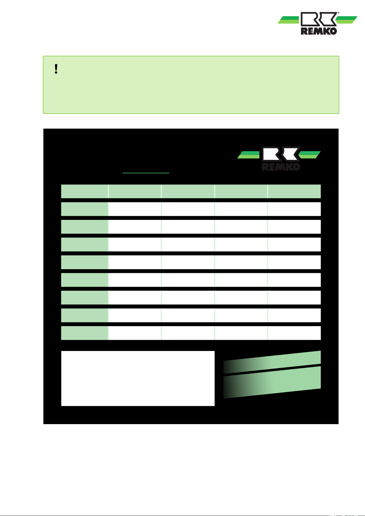
NOTICE!
Filling of heating system with
completely deionised water
Initial filling Year 2 Year 3 Year 4
Filled on
System volume
[litres]
°dH value
pH value
Conductivity
[µS/cm]
Conditioning agent
(name and quantity)
Molybdenum
content
[mg/l]
Signature
Technical changes and errors reserved.
Your heating contractor:
Perform annual
control measurement!
VDI directive 2035
VDI directive 2035
Perform annual
control measurement!
Heat pump systems and components from REMKO must be filled and operated with deionised water
(completely desalinated). W
from us. Full protection with glycol should be used in cooling systems. The system water should be tested
each time the plant is serviced, but at least once a year. Damage that results from non-compliance is not
covered by the guarantee. Below you will find a suitable form for documenting the filling of the system.
e also recommend the use of the complete heating protection unit available
Fig. 43: Form for logging filling with completely deionised water
Media pumped by the Grundfos pump
The pump is suitable for circulation of the following
media:
49
n Pure, low viscosity
explosive media without solid or long-fibre
components
n Mineral oil free coolants
, non-aggressive and non-

REMKO LWM series
n Softened water
The kinematic viscosity of water is ϑ= 1 mm2/s (1
cSt) at 20 °C. If you use the pump to pump liquids
with a dif
will be reduced.
Example: A water-glycol mixture with 50% glycol
content has a viscosity of approx. 10 mm2/s (10
cSt) at 20 °C. Then the pumping capacity is
reduced by approx. 15 %.
No additives must be added to the water which
could impair the function of the pump.
The viscosity of the pumped medium must be
taken into account when designing the pump.
ferent viscosity, the max. pump pressure
9 Commissioning the
refrigeration system
Commissioning
NOTICE!
Commissioning should only be performed and
documented by specially trained personnel.
Observe the operating manual for the indoor
units and outdoor components when commissioning the entire system.
Once all the components have been connected
and tested, the system can be put into operation. A
functional check should be performed to verify its
correct function and identify any unusual operating
behaviour prior to handing it over to the operator
This check is dependent on the installed indoor
units. The processes are specified in the operating
manual for the indoor units being commissioned.
.
Functional checks and test run
Check the following points:
n Leak tightness of the cooling cycle
n Compressor and fan running smoothly
n Issue of cold air in heating mode.
n Function test of all program sequences.
n Check of the surface temperature of the suc-
tion pipe and that the vaporiser is not overheating. To measure the temperature, hold the
thermometer to the suction pipe and subtract
the boiling point temperature reading on the
pressure gauge from the measured temperature.
n Record the measured temperatures in the
commissioning report.
.
50

Function test of heating operating mode
1. Open the on-site valves.
2. Check all connections for leaks with suitable
leak detectors. If leaks are found, the faulty
connection must be remedied.
3. Activate the main circuit breaker or fuse.
4. Program the Smart-Control T
5. Switch on heating mode
Due to the turn on delay
will start up a few minutes later.
6. Check all regulating, control and safety
devices for function and correct adjustment
during the test run.
7. Measure all cooling data and record the
measured values in the commissioning
report.
ouch.
, the compressor
CAUTION!
Danger of injury from refrigerant!
Refrigerant degreases the skin on contact and
may cause cold burns.
Therefore:
- W
ear chemical-resistant protective gloves
when undertaking any work involving refrigerants.
-Safety glasses must be worn to protect the
eyes.
NOTICE!
Check the overheating to determine the refrigerant fill quantity.
Final tasks
n Use the Smart-Control T
temperature to the required value.
n Mount all removed parts.
n Familiarise the operator with the system.
NOTICE!
Check that the shut-of
are tight after carrying out any work on the
cooling cycle. Use appropriate sealant products
as necessary.
Adding refrigerant
DANGER!
W
ork on the cooling circuit may be undertaken
only by trained specialist personnel! (technical
specialist category I)
ouch to set the target
f valves and valve caps
NOTICE!
The escape of refrigerant contributes to climatic
change. In the event of escape, refrigerant with
a low greenhouse potential has a lesser impact
on global warming than those with a high
greenhouse potential. This device contains
refrigerant with a greenhouse potential of 1975.
That means the escape of 1 kg of this refrigerant has an ef
1975 times greater than 1 kg CO2, based on
100 years. Do not conduct any work on the
refrigerant circuit or dismantle the device always enlist the help of qualified experts.
fect on global warming that is
DANGER!
Only refrigerant in a liquid state may be used to
fill the cooling cycle!
51

REMKO LWM series
10 Electrical wiring
Important Information
You can find information on the electrical connections of the indoor and outdoor unit, on the
terminal assignment of the I/0 module, as well
as on the circuit diagrams in the separate "Electrical wiring" operating instructions
NOTICE!
For an existing block the heat pump by the
utility (utility switching) must be used the control
contact S 16 of the Smart-Control.
11 Before commissioning
Observe the following points before commissioning:
n The heating system is filled with DI water in
accordance with VDI 2035. W
addition of REMKO full heating protection (see
Ä
Chapter 8 ‘Water treatment’ on page 48).
n - A water or system temperature of min. 20°C
in the return flow must be ensured (e.g. with a
heating element/emergency heating operation).
n The entire heating system is rinsed, cleaned
and de-aerated (incl. hydraulic balancing).
n The heat pump is not released if an outside
temperature under 10°C is measured at the
external probe and the water inlet temperature (return flow) is under 15°C.
NOTICE!
No commissioning can take place if the above
named points are not observed. Damage
resulting from this is not covered by the guarantee!
e recommend the
NOTICE!
All connections must be properly insulated in
accordance with applicable standards.
52
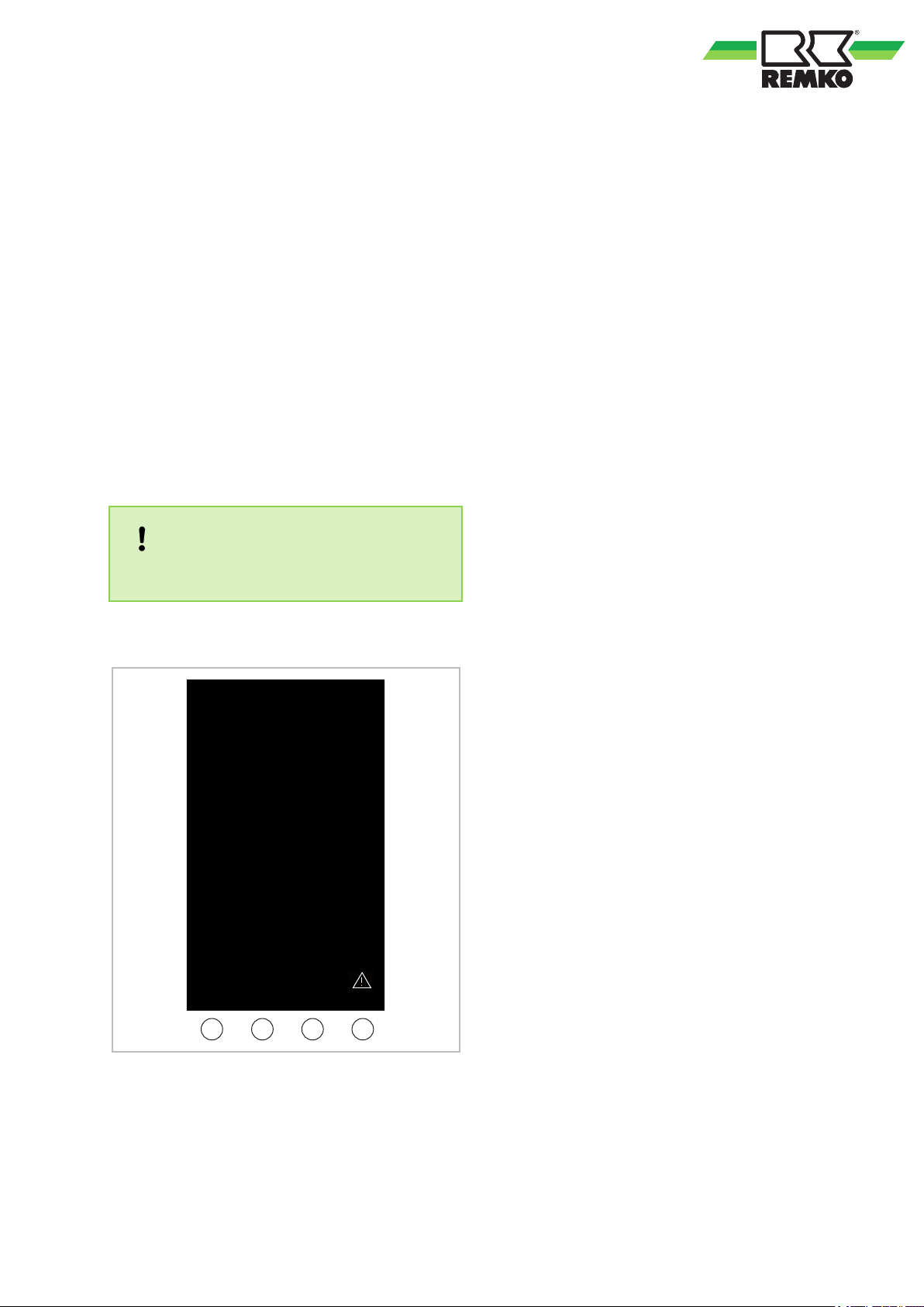
1 2
3 4
12 Commissioning
The Smart-Control Touch is used to operate and
control the complete heating system. The SmartControl Touch is operated via the touch display.
n The unit is pre-installed at the factory
reset of the Smart-Control Touch, the default
parameters are loaded.
n An intensive visual inspection is to be carried
out before the actual commissioning.
n Switch on the power supply.
n Then the pre-installed data is loaded and the
parameters can be set with the help of the
commissioning wizard or in the system configuration. You can find information on this in the
separate operating instructions of the SmartControl Touch.
NOTICE!
Before commissioning the entire system,
including hot water tank, must be filled!
. After a
Function display
Unit operation is intuitive and self-explanatory via
the plain text display on the user interface on the
touch display
and change parameters. Instead, this takes place
by touching the surface of the controller at the
appropriate points. The installation of further functions such as KNX or Smart-Web is possible
through the installation of further supplementary
software available as an accessory.
You can access the expert level by touching the
REMKO logo in the upper right corner of the display. After entering the password (0321) using the
+/- combination and then touching the "Next" and
"OK" displays, the expert level is enabled.
. No buttons are required to adjust
Overview of the controls
Fig. 44: Controls of the Smart Control Touch
1: Overview (quick access)
2: Information (quick access)
3: Settings (quick access)
4: Messages (warnings, information notes and
errors)
53

REMKO LWM series
13 Care and maintenance
Regular care and maintenance assure fault-free
operation and long service life for the heat pump
system.
n T
o perform the statutory leak test where applicable, it is necessary to arrange a yearly maintenance contract with an appropriate specialist
firm.
n The heat pump must be kept free of dirt,
growth and other deposits.
n The unit is to be cleaned with a damp cloth. In
doing so, ensure that no caustic, abrasive or
solvent-based cleaning products are used. Use
of powerful water jets is to be avoided.
n Open the unit regularly and carry out mainte-
nance. For this, the evaporator fins must be
cleaned and impurities removed from the unit if
necessary. Special attention should be paid to
the condensate drainage. Proper drainage of
any condensate that accumulates must always
be ensured.
NOTICE!
14 Temporary shutdown
The system may not be switched off at the mains
power supply even if the heating system is not
used for heating purposes over an extended period
(e.g. holidays)!
n The system is to be switched to "Stand-by"
mode for heating during temporary shutdowns
and for hot water it should be switched to "Of
mode.
n Heating phases can be programmed for the
duration of the period of absence.
n The previous operating mode has to be
switched back on when the shutdown phase is
over.
n Instructions for changing the mode appear in
the corresponding chapter of the Smart-Control
manual.
NOTICE!
In "Standby", the heat pump is in standby
mode. Of the entire system, only the frost-protection function s activated.
f"
The heat pump may only be opened by trained
specialist personnel.
NOTICE!
Please note that an unnoticed power failure can
lead to frost damage!
54

15 Troubleshooting and customer service
General troubleshooting
The unit has been manufactured using state-of-the-art production methods and has been tested several
times to ensure that it works properly
be checked against the following list. Please inform your dealer if the unit is still not working correctly after all
of the functional checks have been performed.
Malfunction Possible causes Remedial measures
. However, in the event that malfunctions should occur, the unit should
The heat pump does
not start or switches
itself of
Heating cycle pump
does not switch of
f
f
Power failure, under-voltage
Defective mains fuse/main switch
turned of
Damaged power supply Repair by specialist firm
Power company off-period
Operational temperature limits too low
or too high
Nominal temperature exceeded, incorrect operating mode
Disconnect the outdoor unit, then
Incorrect pump switching action
f
Check the voltage and, if necessary,
wait for it to come back on
Exchange mains fuse, master switch on
Wait until the power-company off-period
is over and the heat pump starts up as
required
Observe temperature ranges
The set-point temperature has to be
higher than the
heat generator temperature
mode
establish the correct terminal sequence
using the connection plan. Re-establish
voltage to the outdoor unit. Also make
sure that the protective earth is connected correctly
Have pump switching of the "heating
cycle" checked out at specialist level
, check
Heating cycle pumps
fail to switch on
Incorrect operating mode set Check mode
Control board fuse in indoor units
switching cabinet faulty
Incorrect heating program set
Temperature overlapping, e.g. outside
temperature greater than room temperature
Exchange the fuse on the left side of
the control board
Check heating program. In the cold
heating period, we recommend the
‘heating’ operating mode
Check temperature ranges.
Sample test!
55

10
3
8
11
13
1
2
7
6
5
4
14
15
16
17
18
19
12
9
REMKO LWM series
16 General view of unit and spare parts
16.1 Exploded view of the unit LWM 80-150
Fig. 45: Exploded view drawing
We reserve the right to modify the dimensions and design as part of the ongoing technical development
process
56
16.2 Spare parts LWM 80-150
No. Designation LWM 80-150
1 Fin vaporiser
2 Plate heat exchanger
3 Low pressure transducer
4 Smart Serv heating element 7.5 kW
5 Circulation pump
6 Ultrasonic flow rate meter
7 4-way changeover valve
8 High pressure switch
9 High pressure transducer
10 Compressor
11 EEV coil
12 Electronic expansion valve
13 Filter dryer
14 Cover RAL 9006
Aluminium finned grille
15
Graphite finned grille
Camura finned grille
16 Air outlet bottom cover plate RAL 7021
17 Side cover plate RAL 9006
18 Rear pipe inlet cover plate
19 Air intake cover plate
To ensure the correct delivery of spare parts, please always provide the unit type with its corresponding
serial number (see name plate).
On request by providing the serial number
57

REMKO LWM series
Spare parts not illustrated
Designation LWM 80-150
Inverter (frequency converter)
Wave-trap
Hot gas sensor probe (inverter)
Cooling cycle control board
Inverter-control board control cable
Pressure transducer control cable
Temperature sensor
Control board plug set
Complete fan
I/O unit
Smart-Control Touch display surface mounting
Smart-Control Touch indoor unit display
SD card
Coding resistance
To ensure the correct delivery of spare parts, please always provide the unit type with its corresponding
serial number (see name plate).
On request by providing the serial number
58

17 General terms
All-in-one unit
Design in which all refrigeration components are
installed in one housing. No refrigeration work has
to be carried out.
Annual power input factor
The annual power input factor indicates the power
input (e.g. electrical energy) required in order to
achieve a certain benefit (e.g. heating energy). The
annual power input factor includes the energy
required for auxiliary drives.
Bivalent mode
The heat pump provides the entire heating energy
down to a predetermined outdoor temperature
(e.g. -3 °C). If the temperature drops below this
value, the heat pump switches off and the secondary heating appliance takes over the heating, e.g.
a heating boiler.
Coefficient of performance
The current ratio of thermal output produced by the
heat pump to the consumed electrical power is
referred to as the coefficient of performance, as
measured under standardised boundary conditions
according to EN 255 / EN 14511. A coefficient of
performance of 4 means that a usable thermal
output amounting to 4-times the electrical power
consumption is available.
Energy supply company switching
Certain energy supply companies of
iffs for the operation of heat pumps.
When switching off the power supply companies only on the barrier is in contact only
requirement of a heat source (heat pump) is
blocked. Be switched off at monoenergetic
operation, the power supply of the electric
heating element with.
Evaporator
Heat exchanger on a refrigerant plant which uses
the evaporation of a working medium in order to
extract heat from its environment at low temperatures (e.g. the outdoor air).
Expansion valve
Heat pump component for lowering the condensing
pressure on the vapour tension. In addition, the
expansion valve regulates the quantity of injected
refrigerant in relation to the evaporator load.
Heat carrier
Liquid or gas medium (e.g. water
which heat is transported.
fer special tar-
, brine or air), in
Compressor (condenser)
Unit designed for the mechanical conveyance and
compression of gasses. Compression serves to
significantly increase the pressure and temperature of the medium.
Condenser
Heat exchanger on a refrigerant plant which liquefies a working medium in order to transmit heat to
its environment (e.g. the heating system).
Defrost
At outdoor temperatures below 5 °C it is possible
that ice may form on the evaporators of air/water
heat pumps. The removal of this ice is referred to
as defrosting and is undertaken by supplying heat,
either regularly or as requirements dictate. Air/
water heat pumps with circuit reversal are distinguished by their requirements-based, quick and
energy-efficient defrosting system.
Heat pump system
A heat pump system consists of a heat pump and
a heat source system. For brine and water/water
heat pumps, the heat source system must be
made available separately.
Heat source
Medium from which the heat pump derives heat, in
other words, soil, air and water.
Heating output
Flow of heat emitted from the liquefier to the environment. The heating output is the sum of the electrical power consumed by the condenser and the
heat flux obtained from the environment.
Inverter
Power regulator which serves to match the speed
of the compressor motor and the speed of the
evaporator fans to the heating requirement.
59

REMKO LWM series
Limit temperature / bivalence point
Outdoor temperature where the secondary heating
appliance cuts in under bivalent operation.
Monovalent mode
In this mode, the heat pump is the sole heating
appliance in the building all year round. Monovalent mode is primarily used in combination with
brine/water and water/water heat pumps.
Noise
Noise is transmitted in media such as air or water
Essentially there are two types of noise, airborne
sound and solid-borne sound. Airborne sound is
transmitted entirely via the air. Solid-borne sound
is transmitted in solid materials or liquids and is
only partially radiated as airborne sound. The
audible range of sound lies between 20 and
20,000 Hz.
Refrigerant
The working medium used in a refrigerant plant,
e.g. heat pump, is referred to as the refrigerant.
The refrigerant is a liquid which is used for thermal
transfer in a refrigeration plant and which is able to
absorb heat by changing its state at low temperatures and low pressures. A further change of state
at higher temperatures and higher pressure serves
to dissipate this heat.
Refrigerating capacity
Heat flux extracted from the environment by the
evaporator (air, water or soil).
Regulations and guidelines
The erection, installation and commissioning of
heat pumps has to be undertaken by qualified specialist engineers. In doing so, various standards
and directives are to be observed.
Seasonal performance factor
The seasonal performance factor relates to the
ratio of heat content delivered by the heat pump
system to the supplied electrical energy in one
year. It may not be compared to the performance
number. The seasonal performance factor
expresses the reciprocal of the annual power input
factor.
Single energy-source mode
The heat pump covers a large proportion of the
required thermal output. On a few days per year an
.
electrical heating coil supplements the heat pump
under extremely low outdoor temperatures. Dimensioning of the heat pump for air/water heat pumps
is generally based on a limit temperature (also
known as balance point) of approx. -5 °C.
Sound pressure level
The sound pressure level is a comparable characteristic quantity for the radiated acoustic output of a
machine, for example, a heat pump. The noise
emission level at certain distances and acoustic
environments can be measured. The standard is
based on a sound pressure level given as a nominal noise level.
Split AC unit
Design where one part of the device is positioned
outdoors and the other inside the building. Both
units are connected to each other by a refrigerant
pipe.
Storage tank
The installation of a hot-water storage tank is generally recommended in order to extend the running
time of the heat pump under low heat requirements. A storage tank is required for air/water heat
pumps in order to bridge off-periods.
Seal inspection
System operators are obliged to ensure the prevention of refrigerant leakage in accordance with
the directive on substances that deplete the ozone
layer (EC 2037/2000) and the Regulation on Certain Fluorinated Greenhouse Gases (EC
842/2006). In addition, a minimum of one annual
service and inspection must be carried out, as well
as a sealing test for refrigerating plants with a
refrigerant filling weight over 3 kg.
60

18 Index
A
Adding refrigerant ....................... 51
Air change coef
Assembly
Strip foundation ...................... 40
Average condition .................... 11, 12
ficient .................... 32
C
Circulation pump
Characteristic curves .................. 16
Motor protection ...................... 16
Pressure losses ...................... 16
Colder condition ..................... 11, 12
Condensate drainage connection and secure
discharge ............................. 40
Controls, Overview ...................... 53
Cooling mode .......................... 34
COP ............................... 8, 10
D
Diagram, cooling cycle ................... 15
Disposal of equipment .....................6
Dynamic cooling ........................ 34
E
Emergency-heat operation ................ 46
Environmental protection ...................6
F
Function display ........................ 53
H
Heat pump
Design example ...................... 32
Function of the heat pump .............. 31
Layout ............................. 32
Heating coefficient .....................8, 10
Heating performance diagram .............. 33
Humidity probe ......................... 47
P
Passive cooling ......................... 34
Pipe heater ............................ 41
Propellant in accordance with Kyoto Protocol
8, 10
R
Refrigerant circuit diagram ................ 15
Requirement for heat transmission .......... 32
Room temperature probe ................. 47
S
Safe drainage in the event of leakages ....... 41
Safety
Dangers of failure to observe the safety
notes ............................... 4
General ............................. 4
Identification of notes ................... 4
Note for inspection work .................5
Note for installation work ................ 5
Note for maintenance work .............. 5
Personnel qualifications ................. 4
Safety notes for the operator ............. 5
Safety-conscious working ................5
Unauthorised modification ...............5
Unauthorised replacement part manufacture . 5
Set-up
Heat pump .......................... 37
Sound intensity ................... 18, 19, 20
System layout .......................... 35
T
Thermal transfer coefficient ................32
Total sound power level ............. 18, 19, 20
Troubleshooting
General troubleshooting ................ 55
U
Unit description ......................... 31
Unit dimensions ........................ 13
I
Intended use ............................ 5
M
Minimum distances of the heat pump ........ 39
V
Ventilation heat requirement ............... 32
W
Warmer condition .................... 11, 12
Warranty ............................... 6
O
Ordering spare parts ..................... 57
61

REMKO LWM series
62


REMKO QUALITY WITH SYSTEMS
Air-Conditioning | Heating | New Energies
Telephone +49 (0) 5232 606-0
Telefax +49 (0) 5232 606-260
E-mail info@remko.de
URL www.remko.de
REMKO GmbH & Co. KG
Klima- und Wärmetechnik
Im Seelenkamp 12
32791 Lage
Hotline within Germany
+49 (0) 5232 606-0
Hotline International
+49 (0) 5232 606-130
We reserve the right to make technical changes, and provide no guarantee as to the accuracy of this data!
 Loading...