


Assembly and operating instructions
REMKO Heating cycle groups HGM / HGU
Instructions for the Technician
0154-2016-12 Edition 1, en_GB
Read the instructions prior to performing any task!

Read these operating instructions carefully before commissioning / using this device!
These instructions are an integral part of the system and must
always be kept near or on the device.
Subject to modifications; No liability accepted for errors or misprints!
Installation and operating instructions (translation of the original)

Table of contents
1 Safety and usage instructions............................................................................................................. 4
1.1 General safety notes....................................................................................................................... 4
1.2 Identification of notes...................................................................................................................... 4
1.3 Personnel qualifications.................................................................................................................. 4
1.4 Dangers of failure to observe the safety notes................................................................................ 4
1.5 Safety-conscious working............................................................................................................... 4
1.6 Safety instructions for the operator................................................................................................. 5
1.7 Safety notes for installation and inspection tasks........................................................................... 5
1.8 Unauthorised modification and changes......................................................................................... 5
1.9 Intended use................................................................................................................................... 5
1.10 Safety-conscious working............................................................................................................. 5
1.11 Warranty........................................................................................................................................ 5
1.12 Transport and packaging.............................................................................................................. 6
1.13 Environmental protection and recycling........................................................................................ 6
2 Technical data....................................................................................................................................... 7
2.1 Unit data for pump groups HGM / HGU.......................................................................................... 7
2.2 Unit dimensions and pump group components HGM..................................................................... 8
2.3 Unit dimensions and pump group components HGU...................................................................... 9
2.4 Pump unit data.............................................................................................................................. 10
2.5 Pump unit dimensions................................................................................................................... 11
2.6 Pressure losses............................................................................................................................. 11
2.7 Delivery heights and electrical power............................................................................................ 12
3 Unit description................................................................................................................................... 12
4 Installation and assembly.................................................................................................................. 13
4.1 Installation..................................................................................................................................... 13
4.2 Wall installation............................................................................................................................. 13
4.3 Installation on the distributor......................................................................................................... 15
4.4 Mounting the actuator .................................................................................................................. 16
4.5 Gravity brake................................................................................................................................. 17
4.6 Replace the inlet and the return flow............................................................................................. 17
4.7 Replacement of the pump............................................................................................................. 18
4.8 Positioning of the electric cables................................................................................................... 19
4.9 Electrical wiring............................................................................................................................. 19
4.10 Installation example.................................................................................................................... 21
5 Troubleshooting.................................................................................................................................. 22
6 Exploded view and spare parts......................................................................................................... 24
6.1 HGM.............................................................................................................................................. 24
6.2 HGU.............................................................................................................................................. 25
7 Index..................................................................................................................................................... 26
3

REMKO Heating cycle groups
1 Safety and
usage instructions
1.1 General safety notes
Carefully read the operating manual before commissioning the units for the first time. It contains
useful tips and notes such as hazard warnings to
prevent personal injury and material damage.
Failure to follow the directions in this manual not
only presents a danger to people, the environment
and the system itself, but will void any claims for
liability.
Keep this operating manual and the refrigerant
data sheet near to the units.
1.2 Identification of notes
This section provides an overview of all important
safety aspects for proper protection of people and
safe and fault-free operation.The instructions and
safety notes contained within this manual must be
observed in order to prevent accidents, personal
injury and material damage.
Notes attached directly to the units must be
observed in their entirety and be kept in a fully
legible condition.
Safety notes in this manual are indicated by symbols. Safety notes are introduced with signal words
which help to highlight the magnitude of the danger
in question.
DANGER!
CAUTION!
This combination of symbol and signal word
warns of a potentially hazardous situation,
which if not avoided may cause injury or material and environmental damage.
NOTICE!
This combination of symbol and signal word
warns of a potentially hazardous situation,
which if not avoided may cause material and
environmental damage.
This symbol highlights useful tips and recommendations as well as information for efficient
and fault-free operation.
1.3 Personnel qualifications
Personnel responsible for commissioning, operation, maintenance, inspection and installation must
be able to demonstrate that they hold a qualification which proves their ability to undertake the
work.
Contact with live parts poses an immediate
danger of death due to electric shock. Damage
to the insulation or individual components may
pose a danger of death.
DANGER!
This combination of symbol and signal word
warns of a situation in which there is immediate
danger, which if not avoided may be fatal or
cause serious injury.
WARNING!
This combination of symbol and signal word
warns of a potentially hazardous situation,
which if not avoided may be fatal or cause
serious injury.
1.4 Dangers of failure to observe the safety notes
Failure to observe the safety notes may pose a risk
to people, the environment and the units. Failure to
observe the safety notes may void any claims for
damages.
In particular, failure to observe the safety notes
may pose the following risks:
n The failure of important unit functions.
n The failure of prescribed methods of mainte-
nance and repair.
n Danger to people on account of electrical and
mechanical effects.
1.5 Safety-conscious working
The safety notes contained in this manual, the
existing national regulations concerning accident
prevention as well as any internal company
working, operating and safety regulations must be
observed.
4

1.6 Safety instructions for the operator
The operational safety of the units and components is only assured providing they are used as
intended and in a fully assembled state.
n The units and components may only be set up,
installed and maintained by qualified personnel.
n The existing regulations concerning accident
prevention must be adhered to.
n Do not operate units or components with
obvious defects or signs of damage.
n Contact with equipment parts or components
can lead to burns or injury.
n Ensure that electrical energy does not pose a
risk.
n Regulations of the VDE and the local energy
supply company must be adhered to.
1.7 Safety notes for installation and inspection tasks
n The operator must ensure that all inspection
and installation work is carried out by authorised and qualified personnel who have thoroughly read the operating manual.
n Works on the pump/system may only be car-
ried out whilst at a standstill as a matter of principle.
n Appropriate hazard prevention measures must
be taken to prevent risks to people when performing installation, repair, maintenance or
cleaning work on the units.
n The setup, connection and operation of the
units and its components must be undertaken
in accordance with the usage and operating
conditions stipulated in this manual and comply
with all applicable regional regulations.
n Regional regulations and laws as well as the
Water Ecology Act must be observed.
n The power supply should be adapted to the
requirements of the units.
n The units and components must be kept at an
adequate distance from flammable, explosive,
combustible, abrasive and dirty areas or
atmospheres.
n Safety devices may not be modified or
bypassed.
Modifications or changes to units and components
are not permitted and may cause malfunctions.
Safety devices may not be modified or bypassed.
Original replacement parts and accessories
authorised by the manufacturer ensure safety. The
use of other parts may invalidate liability for
resulting consequences.
1.9 Intended use
The heating cycle group is only approved for operation as a heating cycle group. It serves to transport the operating medium of water into closed
heating cycles.
Any different or additional use is a non-intended
use. The manufacturer/supplier assumes no liability for damages arising from a non-intended use.
The user bears the sole risk in such cases.
Intended use also includes working in accordance
with the operating and installation instructions and
complying with the maintenance requirements.
The threshold values specified in the technical
data must not be exceeded.
1.10 Safety-conscious working
The safety notes contained in this manual, the
existing national regulations concerning accident
prevention as well as any internal company
working, operating and safety regulations must be
observed.
1.11 Warranty
For warranty claims to be considered, it is essential
that the ordering party or its representative complete and return the "certificate of warranty" to
REMKO GmbH & Co. KG at the time when the
units are purchased and commissioned.
The warranty conditions are detailed in the "General business and delivery conditions". Furthermore, only the parties to a contract can conclude
special agreements beyond these conditions. In
this case, contact your contractual partner in the
first instance.
1.8 Unauthorised modification and changes
The operational safety of the pump group that was
delivered is guaranteed only with intended use in
accordance with section 1.9 of the operating
instructions. Under no circumstances should the
threshold values specified in the datasheet be
exceeded.
5

REMKO Heating cycle groups
1.12 Transport and packaging
The devices are supplied in a sturdy shipping container. Please check the equipment immediately
upon delivery and note any damage or missing
parts on the delivery and inform the shipper and
your contractual partner. For later complaints can
not be guaranteed.
WARNING!
Plastic films and bags etc. are dangerous
toys for children!
Why:
- Leave packaging material are not around.
- Packaging material may not be accessible to
children!
1.13 Environmental protection and recycling
Disposing of packaging
All products are packed for transport in environmentally friendly materials. Make a valuable contribution to reducing waste and sustaining raw materials. Only dispose of packaging at approved
collection points.
Disposing of the units and their components
For the manufacture of the units and components,
only recyclable materials have been used. Help
protect the environment by ensuring that the units
or components (for example batteries) are not disposed of in household waste, but only in accordance with local regulations and in an environmentally safe manner, e.g. using authorised disposal
and recycling specialists or council collection
points.
6
2 Technical data
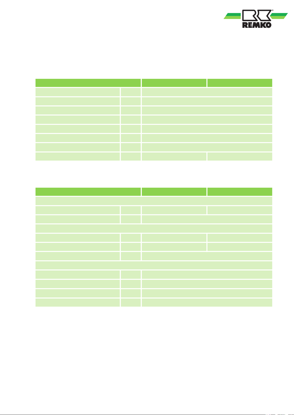
2.1 Unit data for pump groups HGM / HGU
Technical properties
Pump group HGM HGU
Maximum operating temperature °C 95
Max. operating pressure bar 10
Heating cycle side, internal thread Inches 1"
Storage cycle side, external thread Inches 1 1/2"
Pump Wilo Stratos Para 25 / 1-7 T1
Compatible media Water, water-Glycol mixture (maximum 30%)
Thermometer measurement range °C/°F 0-120°C / 30-250°F
Weight kg 6.9 5.85
Materials
Pump group HGM HGU
Ball valve and check valve
Body made of brass: UNI EN 12164 - CW617N UNI EN 12164 - CW614N
Hydraulic seals PTFE, Viton, EPDM
Motorised mixing valve
Body made of brass: UNI EN 12165 - CW617N ---
Turning part made of brass: UNI EN 12164 - CW614N ---
Hydraulic seals EPDM
Insulation half-shells
Body EPP
Body, seal
Body, therm. conductivity (20°C) W/mK 0.039
kg/m
3
60
Body, therm. conductivity (40°C) W/mK 0.041
7
250
380
190
2
1
4
3
6
7
5
4
1
=
2
=
5
=
3
=
4
=
REMKO Heating cycle groups
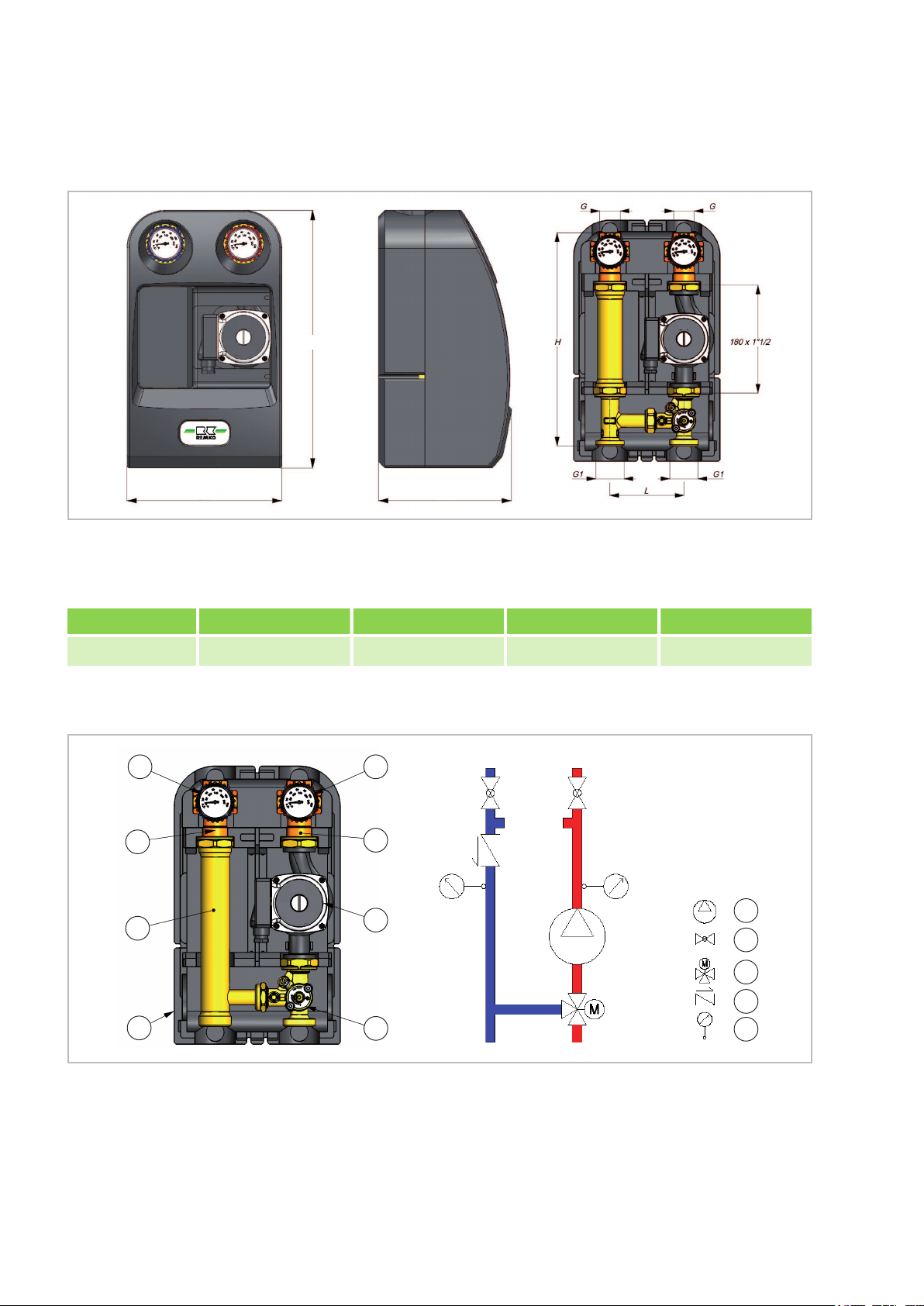
2.2 Unit dimensions and pump group components HGM
Dimensions
Fig. 1: Unit dimensions for pump group HGM
Pump group G G1 L H
HGM 1" IG
Components
1 1/2" AG
125 mm 340 mm
Fig. 2: Pump group components HGM
1: Circulation pump Wilo Stratos Para 25 / 1-7 T1
2: Ball valve
3: Ball valve with integrated check valve
4: Thermometer
5: Motorised mixing valve
6: Extension
7: Insulation
8

2.3 Unit dimensions and pump group components HGU
250
380
190
2
1
4
3
6
5
4
1
=
2
=
=
3
=
4
Dimensions
Fig. 3: Unit dimensions for pump group HGU
Pump group G G1 L H
HGU 1" IG
Components
1 1/2" AG
125 mm 340 mm
Fig. 4: Pump group components HGU
1: Circulation pump Wilo Stratos Para 25 / 1-7 T1
2: Ball valve
3: Ball valve with integrated check valve
9
4: Thermometer
5: Ball valve
6: Insulation

REMKO Heating cycle groups
2.4 Pump unit data
Technical data
Pump group HGM / HGU
Pump type Wilo Stratos Para 25 / 1-7 T1
Maximum delivery volume
Maximum delivery height m 7.0
Speed rpm 1200 - 4450
Mains voltage 1~230V ± 10% in accordance with DIN IEC 60038
Energy Efficiency Index ( EEI ) £ 0.23
Frequency Hz 50/60 Hz
Insulation class F
Enclosure class IP 44
m
3
4.5
Rated input P1 W 5 - 70
Nominal width for pipe connection Rp Inch
es
Connection flange thread G Inch
es
Permitted ambient temperature °C + 40
Maximum relative humidity £ 95%
Heating water (in accordance with VDI 2035/VdTÜV
Water/glycol mixture, maximum mixture ratio is 30% (in
mixtures with glycol, the delivery data of the pump must
be corrected according to the higher viscosity and
depending on the mixture ratio percentage.)
Permitted conveying media
Ethylene/propylene glycol with corrosion protection
- Standard oxygen binding agent
- Standard corrosion protection agent
- Standard combination products
- Standard cooling brines
1"
1 1/2"
Tch 1466)
inhibitors
Permitted medium temperature °C 95
Maximum operating pressure at the pump bar 6.0
Weight kg 2.4
10

2.5 Pump unit dimensions
b4
b5
l
2
l
0
l
1
l
3
a
1
a
2
a
3
21
A
B
A
[m3/h]
B
[m3/h]
[mbar]
[mbar]
a a
Fig. 5: Pump unit dimensions
Wilo Stratos Para
25 / 1-7 T1
l
0
a
1
a
2
a
3
l
1
l
2
l
3
b
4
Dimensions in mm 180 116 32 94 90 56 138 42 41
2.6 Pressure losses
b
5
Fig. 6: Diagram of pressure losses in the pump group HGM / HGU
1: Operational mode; constant differential pressure
2: Operational mode; variable differential pressure
A: Resistance / delivery height [mbar]
B:
Delivery rate [m3/h]
a: Mixing valve R 3/4
11

2
1
1
4
3
A
B
2
1
2
3
4
5
REMKO Heating cycle groups
2.7 Delivery heights and electrical power
Fig. 7: Delivery heights and electrical power of the Wilo Stratos Para 25 / 1-7 T1pump
1: External operating mode via analogue-in 0-10V
2: External operating mode via pump shaft model
(PSM)
3 Unit description
These pump groups HGM / HGU enable circulation
of the heat conducting medium via the inlet. The
pump group HGM regulates the temperature of the
heat conducting medium via a motorised mixing
valve. This pump group with controllable temperature is therefore ideal for operating normal heating
systems with temperature regulation. Temperature
regulation of the Inlet takes place depending on
the inlet and return temperatures of probes S12
and S11.
The pump groups comprise the following: Pump,
ball valve for inlet and return flow, thermometer for
inlet and return flow, check valve against the
heating cycle and thermal insulation.
The pump group HGM also has an integrated
mixing valve
The two insulation half-shells [1, 2] serve as heat
insulation for the pump group and therefore enable
energy to be saved. The pump insulation was
developed to guarantee heat insulation and to prevent the electric motor from overheating. The
check valve that is integrated into the body of the
return flow's ball valve prevents incorrect circulation when the pump is switched off.
Fig. 8: Unit components
A: HGM
B: HGU
1: Front part of the insulation
2: Rear part of the insulation
3: Unit inlet equipped with secondary circuit ball
valve, a motorised mixing valve and a thermometer
4: Unit return flow equipped with secondary circuit
ball valve with an integrated check valve and a
thermometer
5: Wall bracket
12

4 Installation and assembly
2
1
3
4.1 Installation
CAUTION!
Each individual hydraulic component must be
installed by qualified personnel because the
high temperatures and pressures of the liquid
can cause personal injury.
NOTICE!
– Do not use any grease or oils during
assembly, since they can destroy the
seals. If necessary, dirt particles as well as
grease and oil residue must be flushed out
of the supply lines.
– When selecting the operating medium, the
general state-of-the-art must be taken into
consideration (e.g. VDI 2035).
– Protect against external forces (e.g. shock,
impact, vibration).
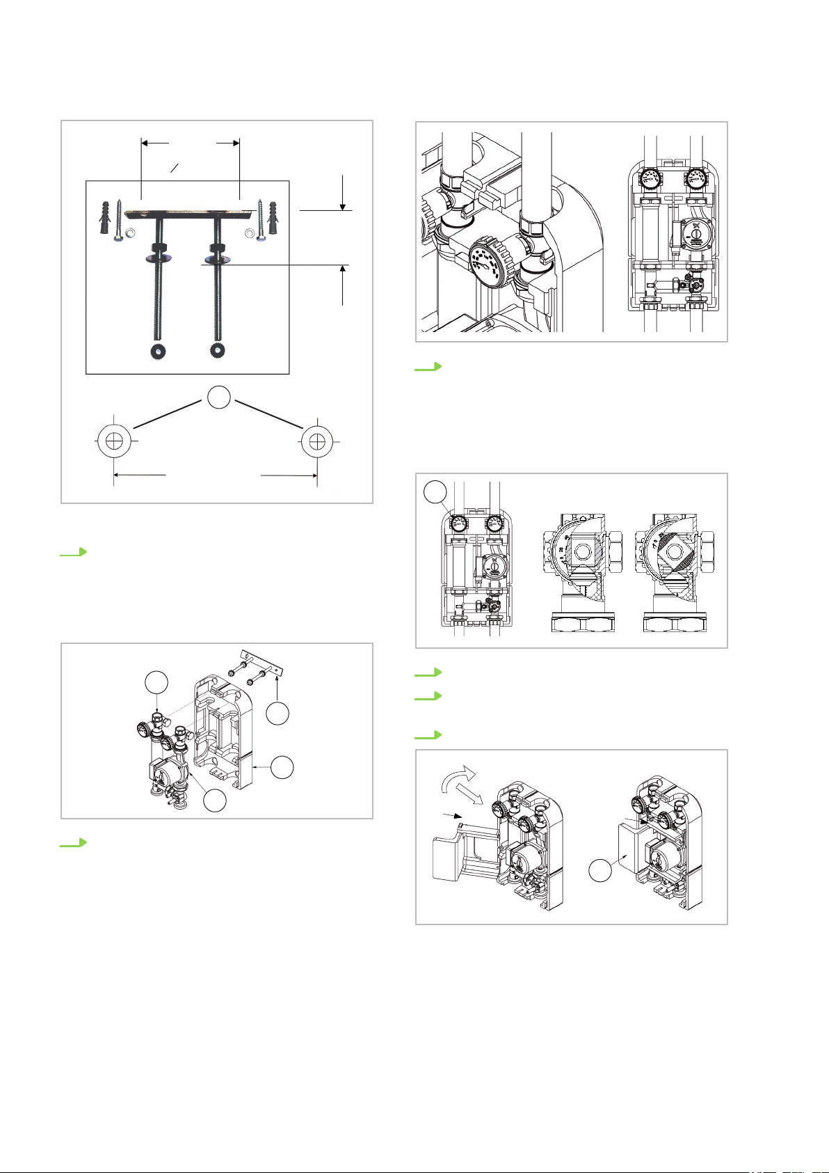
4.2 Wall installation
CAUTION!
Observe the distance between the piping and the
wall specified in point 7.
1. Remove the pre-installed pump group from
the packaging.
2. Open the insulation cover half-shells by
pulling the front side [1] and the rear side [2]
apart.
Possible installations include:
n Wall installation
n Installation on the distributor
After installation, all installation areas must be
checked for leaks.
3. Remove the insulation [3].
4. Remove the inlet [4] and the return flow [5].
5. Install the pump group wall bracket on a suit-
able wall. The wall bracket is equipped with
long holes to aid height adjustment. Fix the
wall bracket to the wall using the enclosed
wall plugs.
13
110 mm
A
110 mm
o 8 mm
45 mm
2
4
5
6
7
3
REMKO Heating cycle groups
8. Turn the controller of the return flow's ball
valve (7) to an angle of 45°; in this position,
the ball valve bypasses the check valve and
nullifies the effect of the valve. This improves
the flow of the water and the air that is to be
bled in the filling phase. Fill the system and
check for leaks.
A: Dowel hole = 8 mm
6. Attach the rear side [2] of the insulation halfshell to the wall bracket. Install the inlet [4]
and the return flow [5] on the wall bracket by
lifting the insulation slightly. The distance
between the pipe axis and the wall surface is
thus around 54 mm.
9. Open the ball valve of the return flow [7].
10. Install the electric cables (see the positioning
of the cables section).
11. Insert the pump's insulation [3].
7. Use the screw connection enclosed in the
packaging to install the piping for the inlet
and the return flow; ensure that the connections are suitable for the pipe dimensions
(connections with flat seals are recommended). If a pump is connected in a series
to the pump group (e.g. boiler pump), in practice, a fixture to separate the heating cycles
hydraulically is to be installed, in order to prevent a malfunction of the two pumps or the
heat pump.
14

1
45
12. Close the pump group using the insulation
half-shell [1].
4.3 Installation on the distributor
The pump groups can be installed on distributors
with an integrated hydraulic compensator, on
standard distributors with a separate hydraulic
compensator and on series distributors. For
optimum installation, the nozzles of the distributor
should be at least 60mm away from the wall.
1. First carry out installation steps 1-4 for wall
installation.
2. To aid installation, start the installation in the
middle of the distributor and then continue
with the outer connections; install the inlet [4]
and the return flow [5] on the distributor using
the screw connection enclosed in the packaging or using the required connecting
pieces (flat-sealing connections are recommended).
3. Insert the insulation half-shell [2]; if the distributor is installed too close to the wall, you
must insert the rear side [2] of the two insulation half-shells before you install the inlet and
the return flow [4] and [5].
15

2
2
3
2
1
3
4
1
a
2
b
5
6 7
REMKO Heating cycle groups
4.4 Mounting the actuator
The actuator is installed as follows:
1. Mount the rotation lock [1] on the mixing
valve housing.
2. Attach the adapter [2] onto the mixing valve
plug [3] until it stops. Observe the flat area!
3. Set the mixing valve plugs so that the nose of
the adapter [a] faces down in the axis direction of the connection thread. The mixing
valve plugs seal the inlet (full bypass mode,
cold) in this position.
4. Set the actuator [4] on the mixing valve axis.
4. Insert the insulation [3] by pushing down the
top side of the rear insulation half-shell [2].
5. Set the rotation direction indicator [5] on the
actuator according to the figure.
6. Attach the hand adjustment handle [6] with
the arrow marking in the blue area [b] on the
mixing drive shaft (condition when delivered:
anti-clockwise against the stop, operational
position "A" Automatic).
7. Attach the screw [7] with the serrated washer
and tighten the screw.
5. Continue as described in point [9] for wall
installation.
6. Open the ball valve of the return flow again.
7. Install the electric cables (see: positioning of
the cables section).
8. Close the pump group using the front part of
the insulation [1].
Fig. 9: Mounting the 3-way mixing valve
16

A B
A
B
9 99
4.5 Gravity brake
The fitting group is delivered pre-assembled. When
operating the heating system, the slot of the gravity
brake assembly must be in the horizontal position.
Fig. 10: Gravity brake
A: Closed
B: Open
Operating position: Stop valve closed, flow is only
possible in the pumping direction.
The gravity brake must be opened for commissioning and maintenance work (filling and rinsing).
Blocking function not active: Stop valve open, flow
is possible in the both directions. During heating
operation, the gravity brake must be moved back
to the operating position.
When the circulation pump is switched off, a
low level of gravity circulation is still possible in
heating systems depending on the operating
pressure and despite the block valve. Block
valves are not leakproof flow limiters.
4.6 Replace the inlet and the return flow
Unmixed heating cycle group
In order to change the flow direction, proceed as
follows:
1. Loosen the connection [9]
2. Replace the inlet and the return line
3. Tighten the connections again
Fig. 11: Inlet
A: Left
B: Right
17

A
B
9 99
9
9
9
9
6
6
4 4
10
1
3
11
10
1
3
11
1
2
3
a
4
6
b
5
7 8
REMKO Heating cycle groups
Mixed heating cycle group
In order to change the flow direction, proceed as
follows:
1. Loosen the connection [9] and the screw [6]
2. Remove the actuator [4]
Fig. 12: Inlet
A: Left
B: Right
3. Loosen the cover [10] and [11] using the
spanner SW46
4. Mount the mixing valve plugs [3] on the other
side
5. Tighten the cover again and apply a torque of
45 Nm
6. Mount the rotation lock [1] on the other side
8. Set the operating switch [8] to manual opera-
tion
9. Set the rotation direction indicator [5] on the
actuator [4] according to the figure
10. Attach the hand adjustment handle [7] on the
mixing valve axis
NOTICE!
The hand adjustment handle can only be lightly
pressed into a locking position. Do not use any
force. Turn the hand adjustment handle clockwise until it stops. The arrow marking of the
hand adjustment handle is in the blue area.
11. Set the actuator on the mixing valve axis
12. Insert the screw [6] with the serrated lock
washer and tighten the screw applying a
torque of > 5 Nm
13. Set the operating switch back to Automatic
operation
7. Set the mixing valve plugs [3] so that the
nose [a] of the adapter [2] faces down. The
mixing valve plugs seal the downward outlet
(full bypass mode, cold) in this position
4.7 Replacement of the pump
The pump groups are constructed in such a way
that pumps of different types and brands can be
connected. If pumps and cable connections from
other manufacturers are to be used, minor
changes to the insulation may be required. They
can be made by the installer.
18

2
4.8 Positioning of the electric cables
The electric cables must be installed by qualified
personnel, in order to avoid endangering people's
safety and material damage. The insulation halfshells were developed in such a way to ensure the
greatest degree of flexibility possible with regard to
cable arrangement in the insulation. There are
appropriate recesses for cable harnesses and
these enable side access to the insulation (2).
The correct mixing valve running direction for
the heating cycle station HGM
If, after the unit has been reinstalled, the wrong
running direction has been set on the mixing valve
motor (controller adjusts to hot and the mixing
valve moves to position 0, instead of 10, the two
connections (brown and black cable) of the mixing
valve motor must be interchanged.
Remove the mixing valve motor
To disassembly the mixing valve motor, lift up the
cover on the rotating head of the motor and completely unscrew the screw in the rotating head. The
mixing valve motor cannot be removed.
4.9 Electrical wiring
DANGER!
All electrical installation work is to be performed by specialist companies. Disconnect
the power supply when connecting the electrical terminals.
The pump and the mixing vale must be connected
to the I/O module of the heat pump according to
the wiring diagram that is enclosed in the heat
pump documentation folder.
The mixing valve must be wired on the I/O module
as follows:
Brown mixing valve cable (mixing valve opens)
Black mixing valve cable (mixing valve closes)
Blue mixing valve cable on N (neutral conductor)
If the controller used requires an inlet/return flow
sensor, they must be inserted in the designated
immersion sleeves.
All the connecting and sensor cables must be
routed downward in the heating cycle station. To
do this, corresponding slots are cut out on the rear
of the thermal insulation shell, where the cable can
be clamped. The inlet and return flow sensor must
be secured against slipping out using the locking
screw.
19

PE N A20 A21
-SMTIO
A20
Mixer 230V
M
N Open
-A20
Mixer
-Heating
cycle floor
bl
br
sw
L-XN PE
A41 GND
-SMTIO
A41
Pump 0-10V
1
M
U N
-A41
Pump
Heating cycle floor
-Power supply A41
br
bl
gnge
ws
br
L
-X
N
PE
A42 GND
-SMTIO
A42
Pump 0-10V
1
M
U N
-A42
Pump
Heating cycle radiator
-Power supply A42
br
bl
gnge
-Heating cycle radiator
ws
br
-Heating
cycle floor
Heating cycle floor
Closed
REMKO Heating cycle groups
Terminal connections when connecting to REMKO Heat pumps, types WKF & WKF compact
Fig. 13: Remko HGM / HGU connection terminals
20

Pump floor cycle
-Heating
cycle pump
heating cycle
-Heating
cycle pump floor
floor heating
Heating cycle pump floor
Heating cycle pump radiator
Pump radiator cycle
Unregulated 230 V
Unregulated 230 V
A
B
C
D
B
AB
A
HGM
HGU
KK
HK
FB
Fig. 14: Connection terminals for installing unregulated heating cycle pumps
4.10 Installation example
Fig. 15: Example hydraulic diagram
A: Outdoor unit
B: WFK indoor unit
C: Storage tank
D: Second heat generator (max. 20 kW)
FB: Floor heating cycle
HK: Heater heating cycle
KK: Cooling cycle
21

REMKO Heating cycle groups
5 Troubleshooting
Fault
description
Pump does
not run when
power supply
is switched
on
Pump makes
noises
Power
supply
undervoltage
Power
supply overvoltage
Motor
jammed
Cause Remedy
Electrical fuse
defective, pump
has no power
Cavitation
caused by insufficient inlet pressure
Power supply
overloaded
Faulty feed from
the energy
supply company
e.g. due to
deposits
Check the fuses, eliminate the power interruption.
Increase the system pressure within the permissible area, check the
delivery height setting and set a lower height if necessary
The motor is switched off in the case of overvoltage or undervoltage. It
starts again automatically as soon as the voltage is again in the permitted area. SSM relay is active. Off: 165 V AC / On: 195 V AC
Faulty feed from the energy supply company. The motor is switched off
in the case of overvoltage or undervoltage. It starts again automatically
as soon as the voltage is again in the permitted area. SSM relay is
active. Off: 265 V AC / On: 245 V AC
If the motor jams, a maximum of 5 restarts at 30 second intervals take
place. If the motor remains jammed, it is switched off permanently. It can
only be switched back on again by switching off the power for more than
30 seconds and then switching it on again. The unjamming programme
runs during each start process. The SSM relay is active as long as the
internal error counter is not ZERO.
Motor overload
Short circuit/
earth
leakage
Contact error The module is
Running
empty
Deposits in the
pump
Motor defective The motor is switched off after a short circuit. It is switched on again
not connected
correctly. Connection between
motor and
module interrupted
Air in the pump The motor is switched off after a defined period of time when running
If the power consumption of the motor exceeds the limit for more than 60
seconds, the "Overload" error is reported. The motor is stopped and
started again after a 30 second pause. If no overloading occurs within
the next 2 minutes, the internal error counter is reset. Otherwise, the
motor is switched off permanently after 5 unsuccessful restarts. This can
only be reset by switching the power off for more than 30 seconds. The
SSM relay is active as long as the internal error counter is not ZERO
after 30 seconds. The motor is switched off permanently after 5 short circuits. This can only be reset by switching the power off for more than 30
seconds. The SSM relay is active as long as the internal error counter is
not ZERO
If the contact between the motor and the module fails, the motor is
switched off. A restart occurs after 30 seconds. After the motor has been
switched off for the fifth time, it is switched off permanently. This can
only be reset by switching the power off for more than 30 seconds. The
SSM relay is active as long as the internal error counter is not ZERO.
under dry running conditions. It starts again after a delay of 30 seconds.
If no dry run occurs within the next 2 minutes, the internal error counter
is reset. Otherwise, the motor is switched off permanently after 5 unsuccessful restarts. This can only be reset by switching the power off for
more than 30 seconds. The SSM relay is active as long as the internal
error counter is not ZERO.
22

Fault
description
Module overtemperature
Cable break Control is defec-
Cause Remedy
The air supply to
the module
cooling element
is restricted
tive, control line
is defective
The motor is switched off if an overtemperature situation occurs. A
restart occurs after 30 seconds. After the motor has been switched off
for the fifth time, it is switched off permanently. This can only be reset by
switching the power off for more than 30 seconds. The SSM relay is
active as long as the internal error counter is not ZERO.
A cable break is registered for the pumps that are controlled via a 0-10 V
signal and that are equipped with software with a cable break function if
the inbound control signal is less than 0.5 V. The pump turns at minimum speed.
23

2
1
4
3
7
8
6
5
REMKO Heating cycle groups
6 Exploded view and spare parts
6.1 HGM
Exploded view of the unit
We reserve the right to modify the dimensions and design as part of the ongoing technical development
process
Spare parts list
No. Designation Description HGM
1 Heating cycle pump Wilo Stratos Para 25 / 1-7 T1 1120909
2 Ball valve, red Ball valve with thermometer, dimensions: G 1 1/2" x G 1" 1121960
3 Ball valve, blue Ball valve with thermometer, dimensions: G 1 1/2" x G 1" 1121962
4 Thermometer, red Thermometer, inlet 1121965
5 Thermometer, blue Thermometer, return flow 1122965
6 Mixing valve 3-way mixing valve, flat sealing, connection G 1 1/2" 1121969
7 Adapter Pipe connection for mixing valve return flow 1122969
8 Insulation Heating cycle group insulator HGM, complete 1121961
Without figure
Mixing valve motor Actuator for mixing valve 230 V, running time 120 s 1121970
EDP
number
Screw connection set Screw connection, dimension: G 1" x 1 1/2" (two units) 1121963
When ordering spare parts, please always state the EDP number, unit number and unit type (see name
plate)!
24

6.2 HGU
2
1
4
3
8
6
5
7
Exploded view of the unit
We reserve the right to modify the dimensions and design as part of the ongoing technical development
process
Spare parts list
No. Designation Description HGU
1 Heating cycle pump Wilo Stratos Para 25 / 1-7 T1 1120909
2 Ball valve, red Ball valve with thermometer, dimensions: G 1 1/2" x G 1" 1121960
3 Ball valve, blue Ball valve with thermometer, dimensions: G 1 1/2" x G 1" 1121962
4 Thermometer, red Thermometer, inlet 1121965
5 Thermometer, blue Thermometer, return flow 1122965
6 Ball valve Ball valve, pump connection, G 1 1/2" AG x G 1 1/2" AG 1122960
7 Adapter Pipe connection for return flow 1123969
8 Insulation Heating cycle group insulator HGU, complete 1121961
Without figure
Screw connection set Screw connection, dimension: G 1" x 1 1/2" (two units) 1121963
When ordering spare parts, please always state the EDP number, unit number and unit type (see name
plate)!
EDP
number
25

REMKO Heating cycle groups
7 Index
A
Assembly
Installation example ...................21
Installation of the actuator ..............16
Installation on the distributor ............15
Positioning of the electric cables .........19
Replacement of the pump ..............18
Wall installation ......................13
C
Components .......................8, 9, 12
D
Delivery heights ........................12
Dimensions ............................9
Pump ..............................11
Pump group ..........................8
E
Electric cabling .........................19
Electrical connection .....................20
Electrical power .........................12
Environmental protection ...................6
I
Install the actuator .......................16
Installation example .....................21
Installation of the actuator .................16
Intended use ............................5
Replace the inlet and return flow ........17, 18
Replace the inlet and the return flow ......17, 18
Replace the pump ......................18
Replacement of the pump .................18
S
Safety
Dangers of failure to observe the safety
notes ...............................4
General .............................4
Identification of notes ...................4
Instructions for the operator ..............5
Note for inspection work .................5
Note for installation work ................5
Personnel qualifications .................4
Safety-conscious working ..............4, 5
Unauthorised modification ...............5
Unauthorised replacement part manufacture . 5
T
Technical properties of the pump groups ......7
U
Unit data
Pump ..............................10
Pump groups .........................7
Unit dimensions .........................9
Pump ..............................11
Pump group ..........................8
Unit disposal ............................6
P
Packaging, disposal ......................6
Positioning of the electric cables ............19
Pressure losses .........................11
Pump group materials .....................7
R
Recycling ..............................6
W
Wall installation .........................13
Warranty ...............................5
26


Consulting
Thanks to intensive training,
our consultants are always
completely up-to-date in terms
of technical knowledge. This has
given us the reputation of being
more than just an excellent,
reliable supplier:
REMKO, a partner
helping you find solutions to
your problems.
Distribution
REMKO offers not just a well
established sales network both
nationally and internationally, but
also has exceptionally highlyqualified sales specialists.
REMKO field staff are more than
just sales representatives: above
all, they must act as advisers to
our customers in air conditioning
and heating technology.
SFlbCustomer Service
Our equipment operates
precisely and reliably. However,
in the event of a fault, REMKO
customer service is quickly at
the scene. Our comprehensive
network of experienced dealers
always guarantees quick and
reliable service.
REMKO INTERNATIONAL
… and also right in your neighbourhood!
Make use of our experience and advice
We reserve the right to make technical changes, and provide no guarantee as to the accuracy of this data!
REMKO GmbH & Co. KG
Air conditioning and heating technology
Im Seelenkamp 12 D-32791 Lage
Postfach 1827 D-32777 Lage
Telephone +49 5232 606-0
Telefax +49 5232 606-2 60
E-mail info@remko.de
Website www.remko.de
 Loading...