

REMEHA Quinta Ace 30, Quinta Ace 45, Quinta Ace 115, Quinta Ace 55, Quinta Ace 65 Installation And User Manual
...
United Kingdom
en
Installation and user manual
High-efficiency wall-hung gas boiler
Quinta Ace 30 - 45 - 55 - 65 - 90 - 115

Dear Customer,
Thank you very much for buying this appliance.
Please read through the manual carefully before using the product, and keep it in a safe place for later reference. In order to
ensure continued safe and efficient operation we recommend that the product is serviced regularly. Our service and customer
service organisation can assist with this.
We hope you enjoy years of problem-free operation with the product.

Contents
7684359 - v.06 - 10012019 3
Contents
1 Safety . . . . . . . . . . . . . . . . . . . . . . . . . . . . . . . . . . . . . . . . . . . . . . . . . . . . . . . . . . . . . . . . . . . . . . . . . . . . . . . . . . . . . . . . . . . . 5
1.1 General safety instructions . . . . . . . . . . . . . . . . . . . . . . . . . . . . . . . . . . . . . . . . . . . . . . . . . . . . . . . . . . . . . . . . . . . . . . . 5
1.2 Recommendations . . . . . . . . . . . . . . . . . . . . . . . . . . . . . . . . . . . . . . . . . . . . . . . . . . . . . . . . . . . . . . . . . . . . . . . . . . . . . 7
1.3 Liabilities . . . . . . . . . . . . . . . . . . . . . . . . . . . . . . . . . . . . . . . . . . . . . . . . . . . . . . . . . . . . . . . . . . . . . . . . . . . . . . . . . . . . . 9
1.3.1 Manufacturer's liability . . . . . . . . . . . . . . . . . . . . . . . . . . . . . . . . . . . . . . . . . . . . . . . . . . . . . . . . . . . . . . . . . . . 9
1.3.2 Installer's liability . . . . . . . . . . . . . . . . . . . . . . . . . . . . . . . . . . . . . . . . . . . . . . . . . . . . . . . . . . . . . . . . . . . . . . . 9
1.3.3 User's liability . . . . . . . . . . . . . . . . . . . . . . . . . . . . . . . . . . . . . . . . . . . . . . . . . . . . . . . . . . . . . . . . . . . . . . . . . .9
2 About this manual . . . . . . . . . . . . . . . . . . . . . . . . . . . . . . . . . . . . . . . . . . . . . . . . . . . . . . . . . . . . . . . . . . . . . . . . . . . . . . . . . . 10
2.1 General . . . . . . . . . . . . . . . . . . . . . . . . . . . . . . . . . . . . . . . . . . . . . . . . . . . . . . . . . . . . . . . . . . . . . . . . . . . . . . . . . . . . . 10
2.2 Additional documentation . . . . . . . . . . . . . . . . . . . . . . . . . . . . . . . . . . . . . . . . . . . . . . . . . . . . . . . . . . . . . . . . . . . . . . . 10
2.3 Symbols used . . . . . . . . . . . . . . . . . . . . . . . . . . . . . . . . . . . . . . . . . . . . . . . . . . . . . . . . . . . . . . . . . . . . . . . . . . . . . . . . 10
2.3.1 Symbols used in the manual . . . . . . . . . . . . . . . . . . . . . . . . . . . . . . . . . . . . . . . . . . . . . . . . . . . . . . . . . . . . . 10
3 Description of the product . . . . . . . . . . . . . . . . . . . . . . . . . . . . . . . . . . . . . . . . . . . . . . . . . . . . . . . . . . . . . . . . . . . . . . . . . . . . 11
3.1 General description . . . . . . . . . . . . . . . . . . . . . . . . . . . . . . . . . . . . . . . . . . . . . . . . . . . . . . . . . . . . . . . . . . . . . . . . . . . .11
3.2 Main components . . . . . . . . . . . . . . . . . . . . . . . . . . . . . . . . . . . . . . . . . . . . . . . . . . . . . . . . . . . . . . . . . . . . . . . . . . . . . 11
3.2.1 Circulating pump . . . . . . . . . . . . . . . . . . . . . . . . . . . . . . . . . . . . . . . . . . . . . . . . . . . . . . . . . . . . . . . . . . . . . . 11
4 Before installation . . . . . . . . . . . . . . . . . . . . . . . . . . . . . . . . . . . . . . . . . . . . . . . . . . . . . . . . . . . . . . . . . . . . . . . . . . . . . . . . . . 12
4.1 Installation regulations . . . . . . . . . . . . . . . . . . . . . . . . . . . . . . . . . . . . . . . . . . . . . . . . . . . . . . . . . . . . . . . . . . . . . . . . . 12
4.2 Choice of the location . . . . . . . . . . . . . . . . . . . . . . . . . . . . . . . . . . . . . . . . . . . . . . . . . . . . . . . . . . . . . . . . . . . . . . . . . . 12
4.2.1 Type plate . . . . . . . . . . . . . . . . . . . . . . . . . . . . . . . . . . . . . . . . . . . . . . . . . . . . . . . . . . . . . . . . . . . . . . . . . . . 12
4.2.2 Location of the boiler . . . . . . . . . . . . . . . . . . . . . . . . . . . . . . . . . . . . . . . . . . . . . . . . . . . . . . . . . . . . . . . . . . . 12
4.3 Ventilation . . . . . . . . . . . . . . . . . . . . . . . . . . . . . . . . . . . . . . . . . . . . . . . . . . . . . . . . . . . . . . . . . . . . . . . . . . . . . . . . . . . 13
4.4 Requirements for CH water connections . . . . . . . . . . . . . . . . . . . . . . . . . . . . . . . . . . . . . . . . . . . . . . . . . . . . . . . . . . . 13
4.5 Requirements for condensate drain line . . . . . . . . . . . . . . . . . . . . . . . . . . . . . . . . . . . . . . . . . . . . . . . . . . . . . . . . . . . . 13
4.6 Requirements for gas connection . . . . . . . . . . . . . . . . . . . . . . . . . . . . . . . . . . . . . . . . . . . . . . . . . . . . . . . . . . . . . . . . . 13
4.7 Requirements for the electrical connections . . . . . . . . . . . . . . . . . . . . . . . . . . . . . . . . . . . . . . . . . . . . . . . . . . . . . . . . . 13
4.8 Requirements for the flue gas outlet system . . . . . . . . . . . . . . . . . . . . . . . . . . . . . . . . . . . . . . . . . . . . . . . . . . . . . . . . .14
4.8.1 Classification . . . . . . . . . . . . . . . . . . . . . . . . . . . . . . . . . . . . . . . . . . . . . . . . . . . . . . . . . . . . . . . . . . . . . . . . . 14
4.8.2 Material . . . . . . . . . . . . . . . . . . . . . . . . . . . . . . . . . . . . . . . . . . . . . . . . . . . . . . . . . . . . . . . . . . . . . . . . . . . . . 16
4.8.3 Dimensions of flue gas outlet pipe . . . . . . . . . . . . . . . . . . . . . . . . . . . . . . . . . . . . . . . . . . . . . . . . . . . . . . . . .17
4.8.4 Length of the air and flue gas pipes . . . . . . . . . . . . . . . . . . . . . . . . . . . . . . . . . . . . . . . . . . . . . . . . . . . . . . . .17
4.8.5 Additional guidelines . . . . . . . . . . . . . . . . . . . . . . . . . . . . . . . . . . . . . . . . . . . . . . . . . . . . . . . . . . . . . . . . . . . 19
4.9 Water quality and water treatment . . . . . . . . . . . . . . . . . . . . . . . . . . . . . . . . . . . . . . . . . . . . . . . . . . . . . . . . . . . . . . . . 20
4.10 Water flow in process heat . . . . . . . . . . . . . . . . . . . . . . . . . . . . . . . . . . . . . . . . . . . . . . . . . . . . . . . . . . . . . . . . . . . . . . 20
4.11 Increasing standard ΔT setting . . . . . . . . . . . . . . . . . . . . . . . . . . . . . . . . . . . . . . . . . . . . . . . . . . . . . . . . . . . . . . . . . . . 20
5 Installation . . . . . . . . . . . . . . . . . . . . . . . . . . . . . . . . . . . . . . . . . . . . . . . . . . . . . . . . . . . . . . . . . . . . . . . . . . . . . . . . . . . . . . . . 22
5.1 Positioning the boiler . . . . . . . . . . . . . . . . . . . . . . . . . . . . . . . . . . . . . . . . . . . . . . . . . . . . . . . . . . . . . . . . . . . . . . . . . . .22
5.2 Rinsing the system . . . . . . . . . . . . . . . . . . . . . . . . . . . . . . . . . . . . . . . . . . . . . . . . . . . . . . . . . . . . . . . . . . . . . . . . . . . . 22
5.3 Connecting the heating circuit . . . . . . . . . . . . . . . . . . . . . . . . . . . . . . . . . . . . . . . . . . . . . . . . . . . . . . . . . . . . . . . . . . . .23
5.4 Connecting the condensate discharge pipe . . . . . . . . . . . . . . . . . . . . . . . . . . . . . . . . . . . . . . . . . . . . . . . . . . . . . . . . . 23
5.5 Gas connection . . . . . . . . . . . . . . . . . . . . . . . . . . . . . . . . . . . . . . . . . . . . . . . . . . . . . . . . . . . . . . . . . . . . . . . . . . . . . . . 24
5.6 Air supply/flue gas outlet connections . . . . . . . . . . . . . . . . . . . . . . . . . . . . . . . . . . . . . . . . . . . . . . . . . . . . . . . . . . . . . .24
5.6.1 Connecting the flue gas outlet and air supply . . . . . . . . . . . . . . . . . . . . . . . . . . . . . . . . . . . . . . . . . . . . . . . . 24
5.7 Electrical connections . . . . . . . . . . . . . . . . . . . . . . . . . . . . . . . . . . . . . . . . . . . . . . . . . . . . . . . . . . . . . . . . . . . . . . . . . . 24
5.7.1 Control unit . . . . . . . . . . . . . . . . . . . . . . . . . . . . . . . . . . . . . . . . . . . . . . . . . . . . . . . . . . . . . . . . . . . . . . . . . . 24
5.7.2 Access to the connectors . . . . . . . . . . . . . . . . . . . . . . . . . . . . . . . . . . . . . . . . . . . . . . . . . . . . . . . . . . . . . . . .25
5.7.3 Connection options for the standard PCB . . . . . . . . . . . . . . . . . . . . . . . . . . . . . . . . . . . . . . . . . . . . . . . . . . . 26
5.7.4 Additional control PCBs . . . . . . . . . . . . . . . . . . . . . . . . . . . . . . . . . . . . . . . . . . . . . . . . . . . . . . . . . . . . . . . . .30
6 Before commissioning . . . . . . . . . . . . . . . . . . . . . . . . . . . . . . . . . . . . . . . . . . . . . . . . . . . . . . . . . . . . . . . . . . . . . . . . . . . . . . .32
6.1 Control panel description . . . . . . . . . . . . . . . . . . . . . . . . . . . . . . . . . . . . . . . . . . . . . . . . . . . . . . . . . . . . . . . . . . . . . . . 32
6.1.1 Description of the components . . . . . . . . . . . . . . . . . . . . . . . . . . . . . . . . . . . . . . . . . . . . . . . . . . . . . . . . . . . 32
6.1.2 Description of the home screen . . . . . . . . . . . . . . . . . . . . . . . . . . . . . . . . . . . . . . . . . . . . . . . . . . . . . . . . . . .32
6.1.3 Description of the main menu . . . . . . . . . . . . . . . . . . . . . . . . . . . . . . . . . . . . . . . . . . . . . . . . . . . . . . . . . . . . 32
6.2 Checklist before commissioning . . . . . . . . . . . . . . . . . . . . . . . . . . . . . . . . . . . . . . . . . . . . . . . . . . . . . . . . . . . . . . . . . . 34
6.2.1 Filling the siphon . . . . . . . . . . . . . . . . . . . . . . . . . . . . . . . . . . . . . . . . . . . . . . . . . . . . . . . . . . . . . . . . . . . . . . 34
6.2.2 Filling the system . . . . . . . . . . . . . . . . . . . . . . . . . . . . . . . . . . . . . . . . . . . . . . . . . . . . . . . . . . . . . . . . . . . . . .34
6.2.3 Gas circuit . . . . . . . . . . . . . . . . . . . . . . . . . . . . . . . . . . . . . . . . . . . . . . . . . . . . . . . . . . . . . . . . . . . . . . . . . . . 34
6.2.4 Hydraulic circuit . . . . . . . . . . . . . . . . . . . . . . . . . . . . . . . . . . . . . . . . . . . . . . . . . . . . . . . . . . . . . . . . . . . . . . . 35
6.2.5 Electrical connections . . . . . . . . . . . . . . . . . . . . . . . . . . . . . . . . . . . . . . . . . . . . . . . . . . . . . . . . . . . . . . . . . . 35

Contents
4 7684359 - v.06 - 10012019
7 Commissioning . . . . . . . . . . . . . . . . . . . . . . . . . . . . . . . . . . . . . . . . . . . . . . . . . . . . . . . . . . . . . . . . . . . . . . . . . . . . . . . . . . . . 36
7.1 Commissioning procedure . . . . . . . . . . . . . . . . . . . . . . . . . . . . . . . . . . . . . . . . . . . . . . . . . . . . . . . . . . . . . . . . . . . . . . 36
7.2 Gas settings . . . . . . . . . . . . . . . . . . . . . . . . . . . . . . . . . . . . . . . . . . . . . . . . . . . . . . . . . . . . . . . . . . . . . . . . . . . . . . . . . 36
7.2.1 Adjusting to a different gas type . . . . . . . . . . . . . . . . . . . . . . . . . . . . . . . . . . . . . . . . . . . . . . . . . . . . . . . . . . 36
7.2.2 Checking and setting the gas/air ratio . . . . . . . . . . . . . . . . . . . . . . . . . . . . . . . . . . . . . . . . . . . . . . . . . . . . . . 37
7.3 Final instructions . . . . . . . . . . . . . . . . . . . . . . . . . . . . . . . . . . . . . . . . . . . . . . . . . . . . . . . . . . . . . . . . . . . . . . . . . . . . . . 40
8 Settings . . . . . . . . . . . . . . . . . . . . . . . . . . . . . . . . . . . . . . . . . . . . . . . . . . . . . . . . . . . . . . . . . . . . . . . . . . . . . . . . . . . . . . . . . . 41
8.1 Changing the parameters . . . . . . . . . . . . . . . . . . . . . . . . . . . . . . . . . . . . . . . . . . . . . . . . . . . . . . . . . . . . . . . . . . . . . . . 41
8.1.1 Accessing the installer level . . . . . . . . . . . . . . . . . . . . . . . . . . . . . . . . . . . . . . . . . . . . . . . . . . . . . . . . . . . . . .41
8.2 List of parameters . . . . . . . . . . . . . . . . . . . . . . . . . . . . . . . . . . . . . . . . . . . . . . . . . . . . . . . . . . . . . . . . . . . . . . . . . . . . . 41
8.2.1 Description of parameters CU-GH08 control unit . . . . . . . . . . . . . . . . . . . . . . . . . . . . . . . . . . . . . . . . . . . . . 42
9 Maintenance . . . . . . . . . . . . . . . . . . . . . . . . . . . . . . . . . . . . . . . . . . . . . . . . . . . . . . . . . . . . . . . . . . . . . . . . . . . . . . . . . . . . . . 51
9.1 General . . . . . . . . . . . . . . . . . . . . . . . . . . . . . . . . . . . . . . . . . . . . . . . . . . . . . . . . . . . . . . . . . . . . . . . . . . . . . . . . . . . . . 51
9.2 Maintenance message . . . . . . . . . . . . . . . . . . . . . . . . . . . . . . . . . . . . . . . . . . . . . . . . . . . . . . . . . . . . . . . . . . . . . . . . . 51
9.3 Standard inspection and maintenance operations . . . . . . . . . . . . . . . . . . . . . . . . . . . . . . . . . . . . . . . . . . . . . . . . . . . . 51
9.3.1 Checking the water pressure . . . . . . . . . . . . . . . . . . . . . . . . . . . . . . . . . . . . . . . . . . . . . . . . . . . . . . . . . . . . .51
9.3.2 Checking the ionisation current . . . . . . . . . . . . . . . . . . . . . . . . . . . . . . . . . . . . . . . . . . . . . . . . . . . . . . . . . . . 51
9.3.3 Checking the flue gas outlet/air supply connections . . . . . . . . . . . . . . . . . . . . . . . . . . . . . . . . . . . . . . . . . . . 52
9.3.4 Checking the combustion . . . . . . . . . . . . . . . . . . . . . . . . . . . . . . . . . . . . . . . . . . . . . . . . . . . . . . . . . . . . . . . 52
9.3.5 Cleaning the siphon . . . . . . . . . . . . . . . . . . . . . . . . . . . . . . . . . . . . . . . . . . . . . . . . . . . . . . . . . . . . . . . . . . . .52
9.4 Specific maintenance operations . . . . . . . . . . . . . . . . . . . . . . . . . . . . . . . . . . . . . . . . . . . . . . . . . . . . . . . . . . . . . . . . . 53
9.4.1 General . . . . . . . . . . . . . . . . . . . . . . . . . . . . . . . . . . . . . . . . . . . . . . . . . . . . . . . . . . . . . . . . . . . . . . . . . . . . . 53
9.4.2 Removing the front panel . . . . . . . . . . . . . . . . . . . . . . . . . . . . . . . . . . . . . . . . . . . . . . . . . . . . . . . . . . . . . . . .53
9.4.3 Checking the non-return valve . . . . . . . . . . . . . . . . . . . . . . . . . . . . . . . . . . . . . . . . . . . . . . . . . . . . . . . . . . . .53
9.4.4 Reassembling the boiler . . . . . . . . . . . . . . . . . . . . . . . . . . . . . . . . . . . . . . . . . . . . . . . . . . . . . . . . . . . . . . . . 54
10 Troubleshooting . . . . . . . . . . . . . . . . . . . . . . . . . . . . . . . . . . . . . . . . . . . . . . . . . . . . . . . . . . . . . . . . . . . . . . . . . . . . . . . . . . . .55
10.1 Error codes . . . . . . . . . . . . . . . . . . . . . . . . . . . . . . . . . . . . . . . . . . . . . . . . . . . . . . . . . . . . . . . . . . . . . . . . . . . . . . . . . . 55
10.1.1 Warning . . . . . . . . . . . . . . . . . . . . . . . . . . . . . . . . . . . . . . . . . . . . . . . . . . . . . . . . . . . . . . . . . . . . . . . . . . . . . 55
10.1.2 Blocking . . . . . . . . . . . . . . . . . . . . . . . . . . . . . . . . . . . . . . . . . . . . . . . . . . . . . . . . . . . . . . . . . . . . . . . . . . . . . 56
10.1.3 Locking . . . . . . . . . . . . . . . . . . . . . . . . . . . . . . . . . . . . . . . . . . . . . . . . . . . . . . . . . . . . . . . . . . . . . . . . . . . . . 58
10.2 Error memory . . . . . . . . . . . . . . . . . . . . . . . . . . . . . . . . . . . . . . . . . . . . . . . . . . . . . . . . . . . . . . . . . . . . . . . . . . . . . . . . 61
11 Technical specifications . . . . . . . . . . . . . . . . . . . . . . . . . . . . . . . . . . . . . . . . . . . . . . . . . . . . . . . . . . . . . . . . . . . . . . . . . . . . . 62
11.1 Homologations . . . . . . . . . . . . . . . . . . . . . . . . . . . . . . . . . . . . . . . . . . . . . . . . . . . . . . . . . . . . . . . . . . . . . . . . . . . . . . . 62
11.1.1 Certifications . . . . . . . . . . . . . . . . . . . . . . . . . . . . . . . . . . . . . . . . . . . . . . . . . . . . . . . . . . . . . . . . . . . . . . . . . 62
11.1.2 Unit categories . . . . . . . . . . . . . . . . . . . . . . . . . . . . . . . . . . . . . . . . . . . . . . . . . . . . . . . . . . . . . . . . . . . . . . . .62
11.1.3 Directives . . . . . . . . . . . . . . . . . . . . . . . . . . . . . . . . . . . . . . . . . . . . . . . . . . . . . . . . . . . . . . . . . . . . . . . . . . . . 62
11.1.4 Factory test . . . . . . . . . . . . . . . . . . . . . . . . . . . . . . . . . . . . . . . . . . . . . . . . . . . . . . . . . . . . . . . . . . . . . . . . . . 62
11.2 Dimensions and connections . . . . . . . . . . . . . . . . . . . . . . . . . . . . . . . . . . . . . . . . . . . . . . . . . . . . . . . . . . . . . . . . . . . . 63
11.3 Electrical diagram . . . . . . . . . . . . . . . . . . . . . . . . . . . . . . . . . . . . . . . . . . . . . . . . . . . . . . . . . . . . . . . . . . . . . . . . . . . . . 64
11.4 Technical data . . . . . . . . . . . . . . . . . . . . . . . . . . . . . . . . . . . . . . . . . . . . . . . . . . . . . . . . . . . . . . . . . . . . . . . . . . . . . . . .65
12 Appendix . . . . . . . . . . . . . . . . . . . . . . . . . . . . . . . . . . . . . . . . . . . . . . . . . . . . . . . . . . . . . . . . . . . . . . . . . . . . . . . . . . . . . . . . . 69
12.1 ErP information . . . . . . . . . . . . . . . . . . . . . . . . . . . . . . . . . . . . . . . . . . . . . . . . . . . . . . . . . . . . . . . . . . . . . . . . . . . . . . . 69
12.1.1 Product fiche . . . . . . . . . . . . . . . . . . . . . . . . . . . . . . . . . . . . . . . . . . . . . . . . . . . . . . . . . . . . . . . . . . . . . . . . . 69
12.1.2 Package sheet . . . . . . . . . . . . . . . . . . . . . . . . . . . . . . . . . . . . . . . . . . . . . . . . . . . . . . . . . . . . . . . . . . . . . . . . 70
12.2 Disposal . . . . . . . . . . . . . . . . . . . . . . . . . . . . . . . . . . . . . . . . . . . . . . . . . . . . . . . . . . . . . . . . . . . . . . . . . . . . . . . . . . . . 71
12.2.1 Disposal and recycling . . . . . . . . . . . . . . . . . . . . . . . . . . . . . . . . . . . . . . . . . . . . . . . . . . . . . . . . . . . . . . . . . .71
12.3 EC declaration of conformity . . . . . . . . . . . . . . . . . . . . . . . . . . . . . . . . . . . . . . . . . . . . . . . . . . . . . . . . . . . . . . . . . . . . .71
12.4 Optional electrical connections . . . . . . . . . . . . . . . . . . . . . . . . . . . . . . . . . . . . . . . . . . . . . . . . . . . . . . . . . . . . . . . . . . . 72
12.4.1 Electronics extension box for extension PCBs . . . . . . . . . . . . . . . . . . . . . . . . . . . . . . . . . . . . . . . . . . . . . . . 72
1 Safety
7684359 - v.06 - 10012019 5
1.1 General safety instructions
For the installer:
1 Safety
Danger
If you smell gas:
1. Do not use naked flames, do not smoke and
do not operate electrical contacts or switches
(doorbell, lighting, motor, lift etc).
2. Shut off the gas supply.
3. Open the windows.
4. Trace possible leaks and seal them off
immediately.
5. If the leak is upstream of the gas meter, notify
the gas company.
Danger
If you smell flue gases:
1. Switch the boiler off.
2. Open the windows.
3. Trace possible leaks and seal them off
immediately.
Caution
After maintenance or repair work, check the
entire heating installation to ensure that there are
no leaks.
For the end user:

1 Safety
6 7684359 - v.06 - 10012019
Danger
If you smell gas:
1. Do not use naked flames, do not smoke and
do not operate electrical contacts or switches
(doorbell, lighting, motor, lift etc).
2. Shut off the gas supply.
3. Open the windows.
4. Report any leaks immediately.
5. Evacuate the property.
6. Contact a qualified installer.
Danger
If you smell flue gases:
1. Switch the boiler off.
2. Open the windows.
3. Report any leaks immediately.
4. Evacuate the property.
5. Contact a qualified installer.
Warning
Do not touch the flue gas pipes. Depending on
the boiler settings, the temperature of the flue gas
pipes can rise to over 60°C.
Warning
Do not touch radiators for long periods.
Depending on the boiler settings, the temperature
of the radiators can rise to over 60°C.
Warning
Be careful when using the domestic hot water.
Depending on the boiler settings, the temperature
of domestic hot water can rise to over 65°C.
Warning
The use of the boiler and the installation by you
as the end-user must be limited to the operations
described in this manual. All other actions may
only be undertaken by a qualified fitter/engineer.
Warning
The condensation drain must not be changed or
sealed. If a condensate neutralisation system is
used, the system must be cleaned regularly in
accordance with the instructions provided by the
manufacturer.

1.2 Recommendations
7684359 - v.06 - 10012019 7
1 Safety
Caution
Ensure that the boiler is regularly serviced.
Contact a qualified installer or arrange a
maintenance contract for the servicing of the
boiler.
Caution
Only genuine spare parts may be used.
Important
Regularly check for the presence of water and
pressure in the heating installation.
Danger
This appliance can be used by children aged
eight and above and people with a physical,
sensory or mental disability, or with a lack of
experience and knowledge, provided they are
supervised and instructed in how to use the
appliance in a safe manner and understand the
associated dangers. Children must not be
allowed to play with the appliance. Cleaning and
user maintenance should not be carried out by
children without adult supervision.
Warning
Installation and maintenance of the boiler must be
carried out by a qualified installer in accordance
with local and national regulations.
Warning
The installation and maintenance of the boiler
must be undertaken by a qualified installer in
accordance with the information in the supplied
manual, doing otherwise may result in dangerous
situations and/or bodily injury.
Warning
Removal and disposal of the boiler must be
carried out by a qualified installer in accordance
with local and national regulations.
Warning
If the mains lead is damaged, it must be replaced
by the original manufacturer, the manufacturer's
dealer or another suitably skilled person to
prevent hazardous situations from arising.
1 Safety
8 7684359 - v.06 - 10012019
Warning
Always disconnect the mains supply and close
the main gas tap when working on the boiler.
Warning
Check the entire system for leaks after
maintenance and servicing work.
Danger
For safety reasons, we recommend fitting smoke
and CO alarms at suitable places in your home.
Caution
Make sure the boiler can be reached at all
times.
The boiler must be installed in a frost-free area.
If the power cord is permanently connected, you
must always install a main bipolar switch with
an opening gap of at least 3 mm (BS EN
60335-1).
Drain the boiler and central heating system if
you are not going to use your home for a long
time and there is a chance of frost.
The frost protection does not work if the boiler is
out of operation.
The boiler protection only protects the boiler,
not the system.
Check the water pressure in the system
regularly. If the water pressure is lower than 0.8
bar, the system must be topped up
(recommended water pressure between 1.5 and
2 bar).
Important
Keep this document near to the boiler.
Important
Only remove the casing for maintenance and
repair operations. Refit all panels when
maintenance work and servicing are complete.
Important
Instruction and warning labels must never be
removed or covered and must be clearly legible
throughout the entire service life of the boiler.
Damaged or illegible instructions and warning
stickers must be replaced immediately.
Important
Modifications to the boiler require the written
approval of Remeha.

1.3 Liabilities
7684359 - v.06 - 10012019 9
1 Safety
1.3.1 Manufacturer's liability
Our products are manufactured in compliance with the
requirements of the various Directives applicable. They
are therefore delivered with the marking and any
documents necessary. In the interests of the quality of
our products, we strive constantly to improve them. We
therefore reserve the right to modify the specifications
given in this document.
Our liability as manufacturer may not be invoked in the
following cases:
Failure to abide by the instructions on installing and
maintaining the appliance.
Failure to abide by the instructions on using the
appliance.
Faulty or insufficient maintenance of the appliance.
1.3.2
Installer's liability
The installer is responsible for the installation and initial
commissioning of the appliance. The installer must
observe the following instructions:
Read and follow the instructions given in the manuals
provided with the appliance.
Install the appliance in compliance with prevailing
legislation and standards.
Carry out initial commissioning and any checks
necessary.
Explain the installation to the user.
If maintenance is necessary, warn the user of the
obligation to check the appliance and keep it in good
working order.
Give all the instruction manuals to the user.
1.3.3 User's liability
To guarantee optimum operation of the system, you
must abide by the following instructions:
Read and follow the instructions given in the manuals
provided with the appliance.
Call on a qualified professional to carry out installation
and initial commissioning.
Get your installer to explain your installation to you.
Have the required inspections and maintenance
carried out by a qualified installer.
Keep the instruction manuals in good condition close
to the appliance.
2 About this manual
10 7684359 - v.06 - 10012019
2 About this manual
2.1 General
This manual describes the installation, use and maintenance of the Quinta
Ace boiler. This manual is part of all the documentation supplied with the
boiler.
2.2
2.3
Additional documentation
The following documentation is available in addition to this manual:
Water quality instructions
Symbols used
2.3.1 Symbols used in the manual
This manual uses various danger levels to draw attention to special
instructions. We do this to improve user safety, to prevent problems and to
guarantee correct operation of the appliance.
Danger
Risk of dangerous situations that may result in serious personal
injury.
Danger of electric shock
Risk of electric shock.
Warning
Risk of dangerous situations that may result in minor personal
injury.
Caution
Risk of material damage.
Important
Please note: important information.
See
Reference to other manuals or pages in this manual.
AD-4000070-01
17
14
13
10
9
6
7
8
2
1
12
3
4
11
5
18
19
20
16
15
3 Description of the product
7684359 - v.06 - 10012019 11
3 Description of the product
The Quinta Ace boiler is delivered with a combination of the control panel,
control unit and extension PCB. The contents of this manual are based on
the following software and navigation information:
Tab.1 Software and navigation information
Name visible in display Software version
Boiler Quinta Ace CU-GH08 1.4
Control panel HMI T-control MK3 1.29
3.1
General description
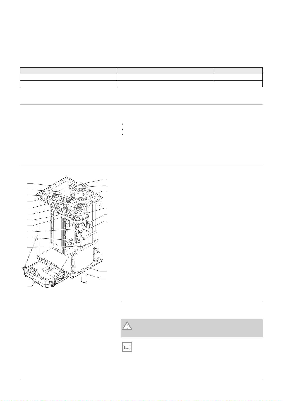
3.2 Main components
Fig.1
Main components
The Quinta Ace boiler is a high-efficiency wall-hung gas boiler with the
following properties:
High-efficiency heating.
Limited emissions of polluting substances.
Ideal choice for cascade configurations.
All Quinta Ace boiler models are supplied without a pump, but with the
required pump connection cables.
1
Casing/air box
2
Heat exchanger (CH)
3
Flue gas measuring point
4
Interior light
5
Flow sensor
6
Ionisation/ignition electrode
7
Mixing tube
8
Non-return valve
9
Combined gas valve unit
10
Return sensor
11
Air intake silencer
12
Instrument box
13
Siphon
15
Automatic air vent
16
Hydraulic pressure sensor
17
Fan
18
Supply line
19
Flue gas discharge pipe
20
Air supply
3.2.1 Circulating pump
A circulation pump is not supplied with this boiler. Take the boiler
resistance and system resistance into account when selecting a pump.
Caution
The pump may have a maximum input of 200 W. Use an auxiliary
relay for a pump with greater power.
See
Technical data, page 65
If possible, install the pump directly under the boiler on the return
connection.
AD-0000103-01
AD-0000014-02
500
min.1000
500
min.
400
350
min.
250
750
4 Before installation
12 7684359 - v.06 - 10012019
4 Before installation
4.1 Installation regulations
Warning
The installer must be registered with Gas Safe and have the
correct ACS qualifications.
Important
Practical guidelines - see the latest version.
4.2
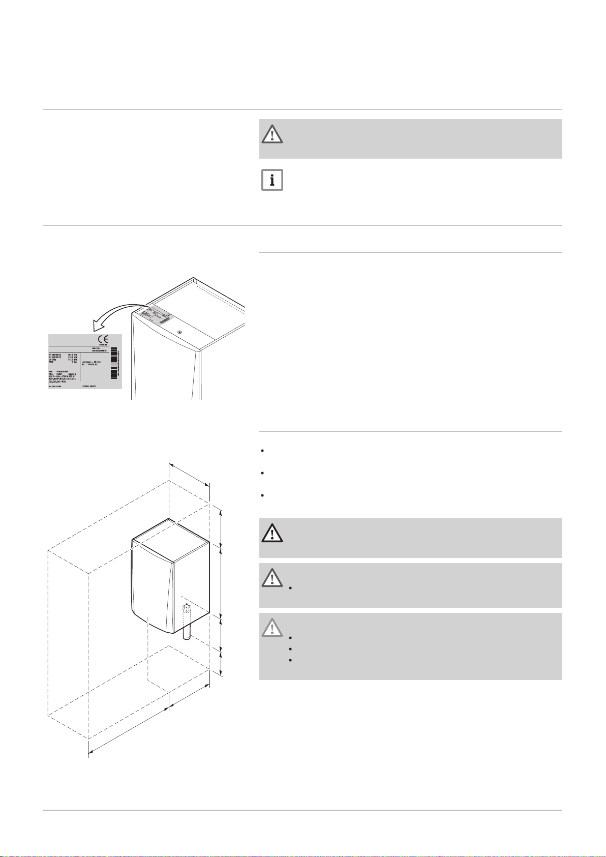
Fig.2 Position of type plate
Fig.3 Installation area
Choice of the location
4.2.1 Type plate
The type plate on top of the boiler features the boiler serial number and
important boiler specifications, for example the model and unit category.
The factory setting codes CN 1 and CN 2 are also stated on the type plate.
4.2.2 Location of the boiler
Use the guidelines and the required installation space as a basis for
determining the correct place to install the boiler.
When determining the correct installation space, take account of the
permitted position of the flue gas discharge and/or air supply outlet.
Ensure that there is sufficient space around the boiler for good access
and ease of maintenance.
Danger
It is forbidden to store, even temporarily, combustible products
and substances in the boiler or near the boiler.
Warning
Fix the appliance to a solid wall capable of bearing the weight of
the boiler when full of water and fully equipped.
Caution
The boiler must be installed in a frost-free area.
The boiler must have an earthed electrical connection.
A connection to the drain must be present for the condensate
drain close to the boiler.

4.3 Ventilation
7684359 - v.06 - 10012019 13
The installation must comply with BS 5540 (part 1 + 2), BS 6644 and
IGEM/UP/10.
4.4 Requirements for CH water connections
When fitting service shut-off valves, position the filling and drain valve,
the expansion vessel and the safety valve between the shut-off valve
and the boiler.
Carry out any welding work required at a safe distance from the boiler or
before the boiler is fitted.
For filling and tapping the boiler, install a filling and drain valve in the
system, preferably in the return.
Install an expansion vessel in the return pipe.
When installing open-vented systems, the cold feed and expansion tank
heights must comply with the requirements laid down in the Health and
Safety Executive publication PM5. The Quinta Ace boilers require a
minimum static height of 3 m (Quinta Ace 30/45/55/65/90 or 5 m ( 115).
4 Before installation
4.5
4.6
Requirements for condensate drain line
The siphon must always be filled with water. This prevents flue gases
from entering the room.
Never seal the condensate drain.
The drain pipe must slope down at least 30 mm per metre, the maximum
horizontal length is 5 metres.
Condensed water must not be discharged into a gutter.
Requirements for gas connection
Before starting work on the gas pipes, turn off the main gas tap.
Before installing, check that the gas meter has sufficient capacity. Take
into account the consumption of all appliances.
Notify the local energy company if the gas meter has insufficient
capacity.
Remove dirt and dust from the gas pipe.
Always perform welding work at a sufficient distance from the boiler.
We recommend installing a gas filter to prevent clogging of the gas
valve unit.
4.7 Requirements for the electrical connections
Establish the electrical connections in accordance with all local and
national current regulations and standards.
Electrical connections must always be made with the power supply
disconnected and only by qualified installers.
The boiler is completely pre-wired. Never change the internal
connections of the control panel.
Always connect the boiler to a well-earthed installation.
The wiring must comply with the instructions in the electrical diagrams.
Follow the recommendations in this manual.
Separate the sensor cables from the 230 V cables
AD-3000924-01
AD-3000925-01
AD-3000926-01
4 Before installation
14 7684359 - v.06 - 10012019
4.8 Requirements for the flue gas outlet system
4.8.1 Classification
Important
The installer is responsible ensuring that the right type of flue
gas outlet system is used and that the diameter and length are
correct.
Always use connection materials, roof terminal and/or outside
wall terminal supplied by the same manufacturer. Consult the
manufacturer for compatibility details.
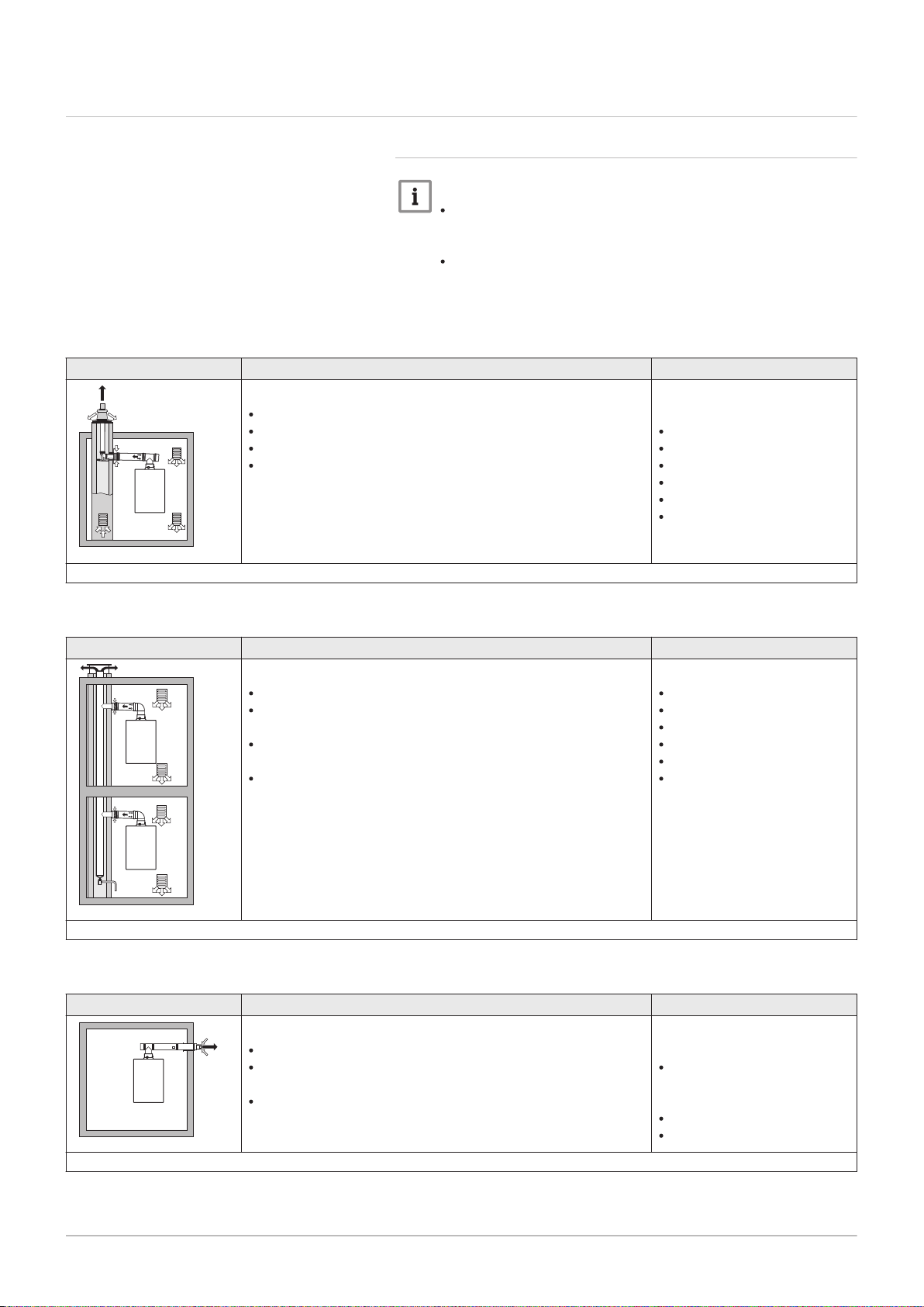
Tab.2 Type of flue gas connection: B
23P
Principle Description
Room-ventilated version
Without down-draught diverter.
Flue gas discharge via the roof.
Air from the installation area.
The IP rating of the boiler is lowered to IP20.
(1) The material must also satisfy the material property requirements from the relevant chapter.
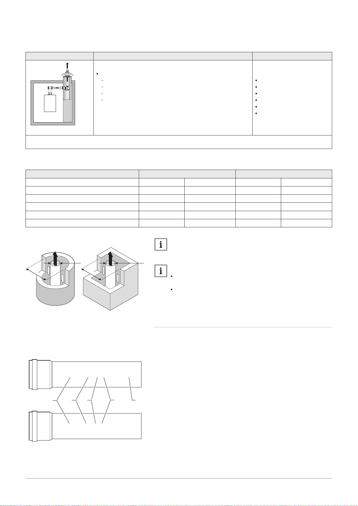
Tab.3 Type of flue gas connection: B
33
Principle Description
Room-ventilated version
Without down-draught diverter.
Joint flue gas discharge via the roof, with guaranteed natural
draft (at all times underpressure in the joint discharge duct).
Flue gas discharge rinsed with air, air from the installation
area (special construction).
The IP rating of the boiler is lowered to IP20.
Permitted manufacturers
(1)
Connection material and roof
terminal:
Centrotherm
Cox Geelen
Muelink & Grol
Natalini
Poujoulat
Ubbink
Permitted manufacturers
(1)
Connection material:
Centrotherm
Cox Geelen
Muelink & Grol
Natalini
Poujoulat
Ubbink
(1) The material must also satisfy the material property requirements from the relevant chapter.
Tab.4 Type of flue gas connection: C
Principle Description
Room-sealed version
Discharge in the outside wall.
Air supply opening is in the same pressure zone as the dis
charge (e.g. a combined outside wall terminal).
Parallel not permitted.
13
Permitted manufacturers
Outside wall terminal and con
nection material:
Remeha, combined with con
nection material from Muelink
& Grol
Cox Geelen
Muelink & Grol
(1) The material must also satisfy the material property requirements from the relevant chapter.
(1)
AD-3000927-01
AD-3000929-02
4 Before installation
7684359 - v.06 - 10012019 15
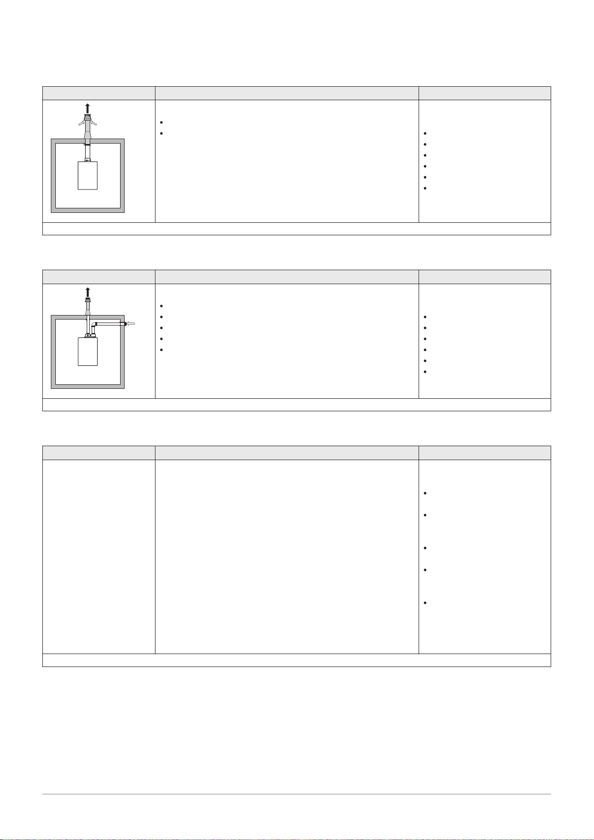
Tab.5 Type of flue gas connection: C
33
Principle Description
Room-sealed version
Flue gas discharge via the roof.
Air supply opening is in the same pressure zone as the dis
charge (e.g. a concentric roof terminal).
(1) The material must also satisfy the material property requirements from the relevant chapter.
Tab.6 Type of flue gas connection: C
53
Principle Description
Connection in different pressure zones
Closed unit.
Separate air supply duct.
Separate flue gas discharge duct.
Discharging into various pressure areas.
The air supply and the flue gas outlet must not be placed on
opposite walls.
Permitted manufacturers
(1)
Roof terminal and connection
material
Centrotherm
Cox Geelen
Muelink & Grol
Natalini
Poujoulat
Ubbink
Permitted manufacturers
(1)
Connection material and roof
terminal:
Centrotherm
Cox Geelen
Muelink & Grol
Natalini
Poujoulat
Ubbink
(1) The material must also satisfy the material property requirements from the relevant chapter.
Tab.7 Type of flue gas connection: C
63
Principle Description
This type of unit is supplied by the manufacturer without an air
supply system and flue gas system.
(1) The material must also satisfy the material property requirements from the relevant chapter.
Permitted manufacturers
(1)
When selecting the material,
please note the following:
Condensed water must flow
back to the boiler.
The material must be resist
ant to the flue gas tempera
ture of this boiler.
Maximum permissible recir
culation of 10%.
The air supply and the flue
gas outlet must not be placed
on opposite walls.
Minimum permitted pressure
difference between the air
supply and the flue gas outlet
is -200 Pa (including -100 Pa
wind pressure).
AD-3000931-01
AD-3000330-03
□
D
Ø
D
AD-3001120-01
EN 14471 - T120 P1 W 1 O50 LI E U0
EN 1856-1 - T120 P1 W VxL40045 G(xx)
1
3
2
4
5
4 Before installation
16 7684359 - v.06 - 10012019
Tab.8 Type of flue gas connection: C
Principle
(1)
Description
Room-sealed version
Air supply and flue gas discharge duct in shaft or ducted:
93
Concentric.
Air supply from existing duct.
Flue gas discharge via the roof.
Inlet opening for the air supply is in the same pressure zone
as the discharge.
Permitted manufacturers
Connection material and roof
terminal:
Centrotherm
Cox Geelen
Muelink & Grol
Natalini
Poujoulat
Ubbink
(1) See table for shaft or duct requirements.
(2) The material must also satisfy the material property requirements from the relevant chapter.
Tab.9 Minimum dimensions of shaft or duct C
93
Version (D) Without air supply With air supply
Rigid 80 mm Ø 130 mm □ 130 x 130 mm Ø 140 mm □ 130 x 130 mm
Rigid 100 mm Ø 160 mm □ 160 x 160 mm Ø 170 mm □ 160 x 160 mm
Rigid 150 mm Ø 200 mm □ 200 x 200 mm Ø 220 mm □ 220 x 220 mm
Concentric 80/125 mm Ø 145 mm □ 145 x 145 mm Ø 145 mm □ 145 x 145 mm
Concentric 100/150 mm Ø 170 mm □ 170 x 170 mm Ø 170 mm □ 170 x 170 mm
Concentric 150/200 mm Ø 270 mm □ 270 x 270 mm - -
(2)
Fig.4 Minimum dimensions of shaft or
duct C
93
Fig.5 Sample string
Important
The shaft must comply with the air density requirements of the
local regulations.
Important
Always clean shafts thoroughly when using lining pipes and/or
an air supply connection.
It must be possible to inspect the lining duct.
4.8.2 Material
Use the string on the flue gas outlet material to check whether it is suitable
for use on this appliance.
1
EN 14471 of EN 1856–1: The material is CE approved according to
this standard. For plastic this is EN 14471, For aluminium and
stainless steel this is EN 1856-1.
2
T120: The material has temperature class T120. A higher number
is also allowed, but not lower.
3
P1: The material falls into pressure class P1. H1 is also allowed.
4
W: The material is suitable for draining condensation water
(W=’wet’). D is not allowed (D=’dry’).
5
E: The material falls into fire resistance class E. Class A to D are
also allowed, F is not allowed. Only applicable to plastic.

Warning
AD-3000962-01
ød
1
L
1
øD
1
7684359 - v.06 - 10012019 17
The coupling and connection methods may vary depending on
the manufacturer. It is not permitted to combine pipes, coupling
and connection methods from different manufacturers. This also
applies to roof feed-throughs and common channels.
The materials used must comply with the prevailing regulations
and standards.
Please contact us to discuss using flexible flue gas outlet
material.
Tab.10 Overview of material properties
Version Flue gas outlet Air supply
Material Material properties Material Material properties
Single-wall, rigid
(1)
Plastic
Stainless steel
Thick-walled,
aluminium
(2)
With CE marking
(2)
Temperature class T120 or
higher
Condensate class W (wet)
Plastic
Stainless steel
Aluminium
Pressure class P1 or H1
Fire resistance class E or bet
(3)
ter
(1) according to EN 14471
(2) according to EN 1856
(3) according to EN 13501-1
4 Before installation
With CE marking
Pressure class P1 or H1
Fire resistance class E or bet
(3)
ter
Fig.6 Dimensions of concentric
connection
4.8.3 Dimensions of flue gas outlet pipe
Warning
The pipes connected to the flue gas adapter must satisfy the
following dimension requirements.
d
External dimensions of flue gas outlet pipe
1
D
External dimensions of air supply pipe
1
L
Length difference between flue gas outlet pipe and air supply pipe
1
Tab.11 Dimensions of pipe
d1 (min-max) D1 (min-max)
(1)
L
(min-max)
1
80/125 mm 79.3 - 80.3 mm 124 - 125.5 mm 0 - 15 mm
100/150 mm 99.3 - 100.3 mm 149 - 151 mm 0 - 15 mm
(1) Shorten the inner pipe if the length difference is too great.
4.8.4 Length of the air and flue gas pipes
The maximum length of the flue gas outlet and air supply channel vary
depending on the appliance type; consult the relevant chapter for the
correct lengths.
Important
When using bends, the maximum chimney length (L) must be
shortened according to the reduction table.
For adaptation to another diameter use approved transitions
The boiler is also suitable for longer chimney lengths and
diameters other than those specified in the tables. Contact us
for more information.
AD-0000028-02
L =
AD-0000029-02
L =
4 Before installation
18 7684359 - v.06 - 10012019
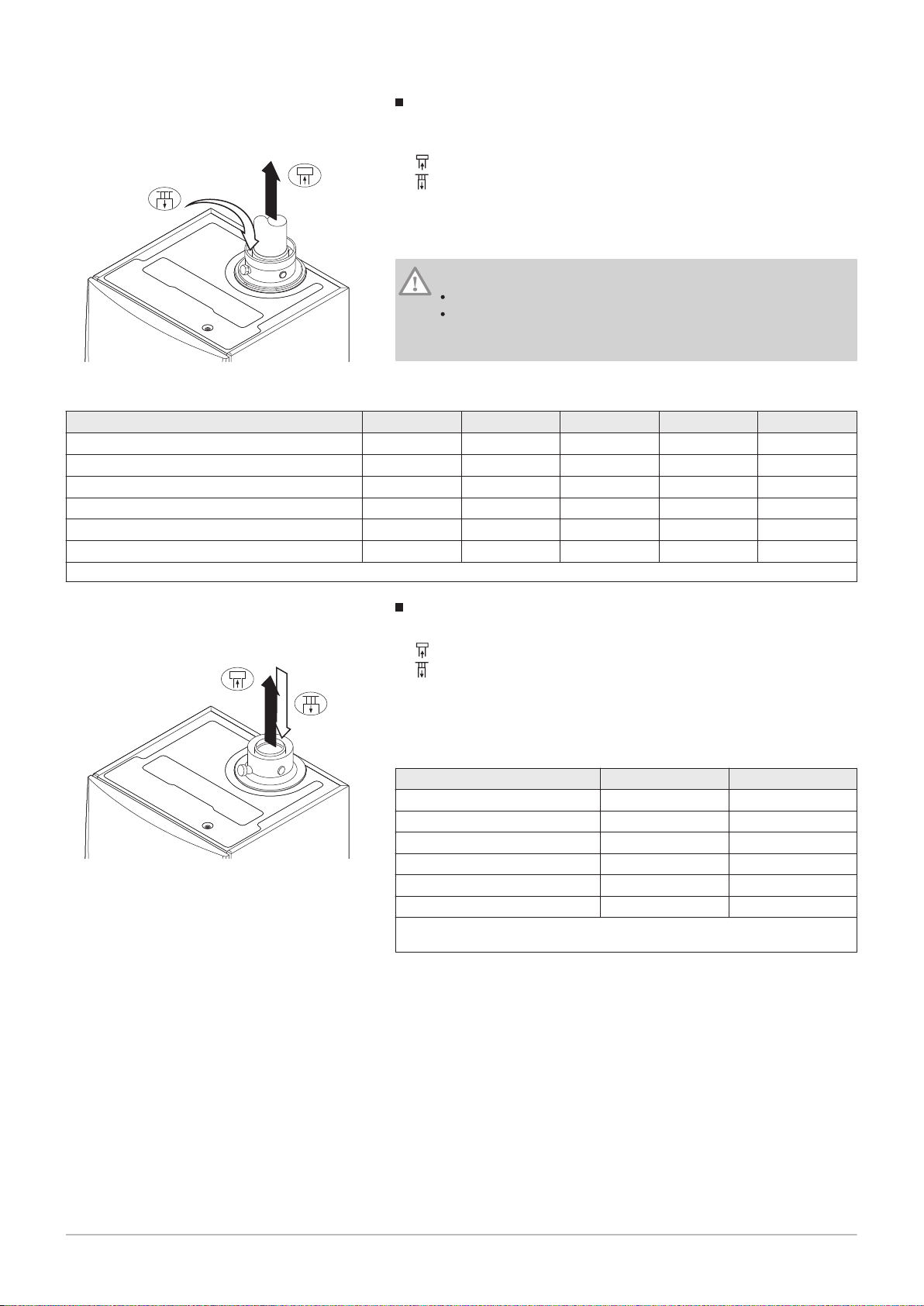
Fig.7 Room-ventilated version
Room-ventilated model (B
L
Length of the flue gas outlet channel to roof feed-through
23P
, B33)
Connecting the flue gas outlet
Connecting the air supply
With a room-ventilated version, the air supply opening stays open; only the
flue gas outlet opening is connected. This will ensure that the boiler
obtains the necessary combustion air directly from the installation area.
Caution
The air supply opening must stay open.
The installation area must be equipped with the necessary air
supply openings. These openings must not be obstructed or
shut off.
Tab.12 Maximum length (L)
Diameter
(1)
Quinta Ace 30 33 m 40 m 40 m
Quinta Ace 45 39 m
Quinta Ace 55 16 m 26 m 39 m
80 mm 90 mm 100 mm 110 mm 130 mm
40 m
40 m
(1)
40 m
(1)
40 m
40 m
Quinta Ace 65 11 m 17 m 26 m 40 m
Quinta Ace 90 10 m 16 m 24 m 40 m
Quinta Ace 115 8 m 13 m 19 m 38 m
(1) Retaining the maximum chimney length it is possible to use an extra 5 x 90º or 10 x 45º elbows.
(1)
(1)
(1)
40 m
40 m
40 m
40 m
40 m
40 m
(1)
(1)
(1)
(1)
(1)
(1)
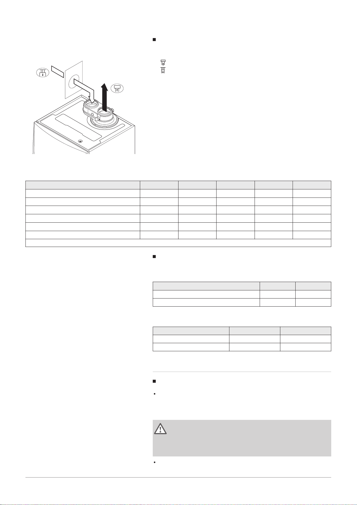
Fig.8 Room-sealed version (concentric)
Room-sealed model (C13, C33, C63, C93)
Connecting the flue gas outlet
Connecting the air supply
With a room-sealed version, both the flue gas outlet and the air supply
openings are connected (concentrically).
Tab.13 Maximum chimney length (L)
Diameter
(1)
Quinta Ace 30 20 m 20 m
Quinta Ace 45 20 m
Quinta Ace 55 8 m
Quinta Ace 65 4 m 18 m
Quinta Ace 90 4 m 17 m
Quinta Ace 115 - 13 m
(1) Retaining the maximum chimney length it is possible to use an extra 5 x 90º
or 10 x 45º elbows.
80/125 mm 100/150 mm
(1)
20 m
(1)
20 m
Connection in different pressure areas (C53)
AD-0000030-02
= L +
7684359 - v.06 - 10012019 19
4 Before installation
Fig.9
Different pressure areas
L
Total length of the flue gas outlet and air supply duct
Connecting the flue gas outlet
Connecting the air supply
An 80/80 or 100/100 mm flue gas adapter (accessory) must be fitted for
this connection.
Combustion air supply and flue gas discharge are possible in different
pressure areas and semi-CLV systems, with the exception of the coastal
area. The maximum permitted height difference between the combustion
air supply and the flue gas outlet is 36 m.
Tab.14 Maximum length (L)
Diameter
(1)
Quinta Ace 30 17 m 29 m 40 m
Quinta Ace 45 29 m 40 m
80 mm 90 mm 100 mm 110 mm 130 mm
40 m
(1)
40 m
40 m
Quinta Ace 55 9 m 17 m 27 m 40 m
Quinta Ace 65 5 m 10 m 16 m 34 m
Quinta Ace 90 - - 17 m 37 m
Quinta Ace 115 - - 14 m 31 m
(1) Retaining the maximum chimney length it is possible to use an extra 5 x 90º or 10 x 45º elbows.
(1)
(1)
40 m
40 m
40 m
40 m
40 m
40 m
(1)
(1)
(1)
(1)
(1)
(1)
Reduction table
Tab.15 Pipe reduction for each element used (parallel)
Diameter 80 mm 100 mm
45° bend 1.2 m 1.4 m
90° bend 4.0 m 4.9 m
Tab.16 Pipe reduction for each element used (concentric)
Diameter 80/125 mm 100/150 mm
45° bend 1.0 m 1.0 m
90° bend 2.0 m 2.0 m
4.8.5 Additional guidelines
Installation
For installing the flue gas outlet and air supply materials, refer to the
instructions of the manufacturer of the relevant material. After
installation, check at least all flue gas outlet and air supply parts for
tightness.
Warning
If the flue gas outlet and air supply materials are not installed in
accordance with the instructions (e.g. not leak-proof, not correctly
bracketed), this can result in dangerous situations and/or physical
injury.
Make sure that the flue gas outlet pipe towards the boiler has a sufficient
gradient (at least 50 mm per metre) and that there is a sufficient
4 Before installation
20 7684359 - v.06 - 10012019
condensate collector and discharge (at least 1 m before the outlet of the
boiler). The bends used must be larger than 90° to guarantee the
gradient and a good seal on the lip rings.
Condensation
Direct connection of the flue gas outlet to structural ducts is not
permitted because of condensation.
If condensate from a plastic or stainless steel pipe section can flow back
to an aluminium part in the flue gas outlet, this condensate must be
discharged via a collector before it reaches the aluminium.
Newly installed aluminium flue gas pipes with longer lengths can
produce relatively larger quantities of corrosion products. Check and
clean the siphon more often in this case.
Important
Contact us for more information.
4.9
Water quality and water treatment
4.10 Water flow in process heat
The quality of the CH water must comply with certain limit values, which
can be found in our Water quality instructions. The guidelines in these
instructions must be followed at all times.
In many cases, the boiler and central heating system can be filled with
normal tap water and water treatment will not be necessary.
In process heat applications (for example pasteurisation and drying and
washing processes), the boiler is being used for industrial purposes and
not for central heating. With process heat, the nominal flow (at ΔT 20°C) in
the primary CH circuit must be guaranteed. The flow in the secondary
circuit may vary.
To ensure that this is the case, a flow rate sensor can be fitted, which
locks out the boiler if the flow falls below a specified level (due to a
defective pump or valve, for example).
For this application, adjust the following parameters:
Set parameter DP140 to Process heat .
Set parameters DP005 and DP070 to the required value for this
installation.
If using a DHW sensor; set parameters DP034 and DP006 to the
required value for this installation.
Important
The service life of the boiler may be reduced if it is used for
process heat applications.
4.11
Increasing standard ΔT setting
In some cases, the standard ΔT setting of the boiler will need to be
increased, for example in systems with:
underfloor heating
air heating
district heating
a heat pump.

4 Before installation
7684359 - v.06 - 10012019 21
Tab.17 Increasing standard ΔT setting
Boiler type ΔT setting
Quinta Ace 30
Quinta Ace 45
The standard ΔT setting of 25K can be increased to
a maximum of 40K.
Quinta Ace 55
Quinta Ace 65
Quinta Ace 90
Quinta Ace 115 The standard ΔT setting of 20K can be increased to
a maximum of 35K.
Increase the ΔT setting using parameter GP021. When increasing the ΔT,
the control unit limits the flow temperature to a maximum of 80 °C.
Important
With the increased ΔT setting, the Service Tool will use a substatus to indicate that the limited flow temperature is active.
Prevent the boiler from locking out and ensure a minimal water
circulation by using a bypass or low-loss header.
If a PWM-controlled central heating-pump is controlled by the
boiler control unit, set parameter PP014 to 2.
AD-0000018-02
2
1
5
4
3
5 Installation
22 7684359 - v.06 - 10012019
5 Installation
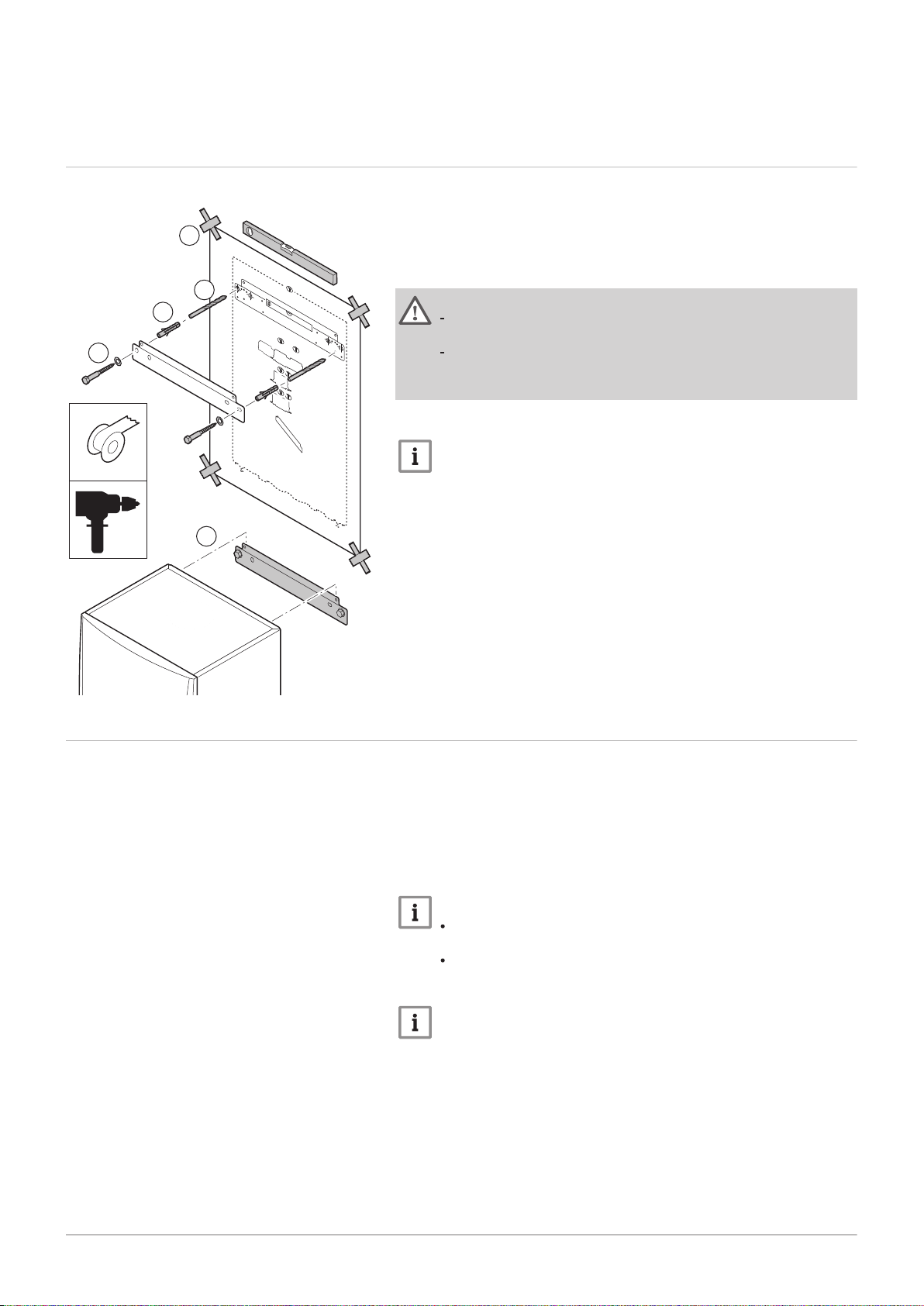
5.1 Positioning the boiler
Fig.10 Mounting the boiler
The fitting bracket on the back of the casing can be used to mount the
boiler directly on the suspension bracket.
The boiler is supplied with a mounting template.
1. Attach the mounting template of the boiler to the wall using adhesive
tape.
Warning
Use a level to check whether the mounting template is hanging
perfectly horizontally.
Protect the boiler against building dust and cover the connection
points for the flue gas outlet and air supply. Only remove this
cover to assemble the relevant connections.
2. Drill 2 holes of Ø 10 mm.
Important
The extra fixing holes in the suspension bracket are intended for
use in the event that one of the two holes is not suitable for the
correct fastening of the plug.
3. Fit the Ø 10 mm plugs.
4. Remove the mounting template.
5. Attach the suspension bracket to the wall with the Ø 10 mm bolts
supplied.
6. Mount the boiler on the suspension bracket.
5.2 Rinsing the system
The installation must be cleaned and flushed in accordance with BS 7593
(2006) and BSRIA BG 33/2014.
Before a new boiler can be connected to an existing or new system, the
entire system must be thoroughly cleaned and flushed. This step is
absolutely crucial. The flushing helps to remove residue from the
installation process (weld slag, fixing products etc.) and accumulations of
dirt (silt, mud etc.)
Important
Flush the system with a volume of water equivalent to at least
three times the volume of the system.
Flush the DHW pipes with at least 20 times the volume of the
pipes.
Important
Due to the presence of an aluminium heat exchanger, suitable
chemicals and the correct use of these chemicals should be
discussed with specialist water treatment companies.
5.3 Connecting the heating circuit
AD-4100110-01
1
2
4
5
4
3
AD-0000024-02
4
1
2
3
7684359 - v.06 - 10012019 23
5 Installation
Fig.11 Connecting the CH flow and CH
return
1. Remove the dust cap from the CH flow connection at the bottom
of the boiler.
2. Fit the outlet pipe for CH water to the CH flow connection.
3. Remove the dust cap from the CH return connection at the
bottom of the boiler.
4. Fit the inlet pipe for CH water to the CH return connection.
5. Install the pump in the CH return pipe (if applicable).
For more information, see
Connecting the PWM pump, page 29
Connecting the standard pump, page 30
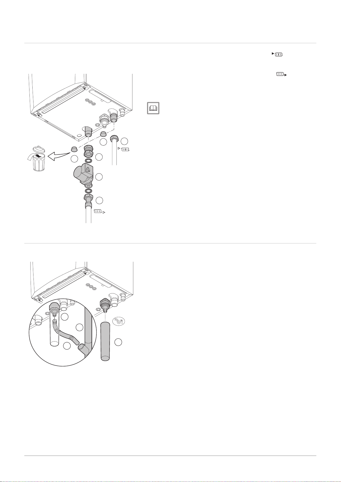
5.4 Connecting the condensate discharge pipe
Fig.12 Connecting the condensate
discharge pipe
1. Fit a plastic drain pipe of Ø 32 mm or larger, terminating in the drain.
2. Insert the flexible condensate drain hose into the pipe.
3. Fit a stench-trap or siphon in the drain pipe.
4. Fit the siphon.
 Loading...