

REMEHA Quinta Ace 30, Quinta Ace 45, Quinta Ace 115, Quinta Ace 55, Quinta Ace 65 Installation And User Manual
...
United Kingdom
en
Installation and user manual
High-efficiency wall-hung gas boiler
Quinta Ace 30 - 45 - 55 - 65 - 90 - 115

Dear Customer,
Thank you very much for buying this appliance.
Please read through the manual carefully before using the product, and keep it in a safe place for later reference. In order to
ensure continued safe and efficient operation we recommend that the product is serviced regularly. Our service and customer
service organisation can assist with this.
We hope you enjoy years of problem-free operation with the product.

Contents
7684359 - v.06 - 10012019 3
Contents
1 Safety . . . . . . . . . . . . . . . . . . . . . . . . . . . . . . . . . . . . . . . . . . . . . . . . . . . . . . . . . . . . . . . . . . . . . . . . . . . . . . . . . . . . . . . . . . . . 5
1.1 General safety instructions . . . . . . . . . . . . . . . . . . . . . . . . . . . . . . . . . . . . . . . . . . . . . . . . . . . . . . . . . . . . . . . . . . . . . . . 5
1.2 Recommendations . . . . . . . . . . . . . . . . . . . . . . . . . . . . . . . . . . . . . . . . . . . . . . . . . . . . . . . . . . . . . . . . . . . . . . . . . . . . . 7
1.3 Liabilities . . . . . . . . . . . . . . . . . . . . . . . . . . . . . . . . . . . . . . . . . . . . . . . . . . . . . . . . . . . . . . . . . . . . . . . . . . . . . . . . . . . . . 9
1.3.1 Manufacturer's liability . . . . . . . . . . . . . . . . . . . . . . . . . . . . . . . . . . . . . . . . . . . . . . . . . . . . . . . . . . . . . . . . . . . 9
1.3.2 Installer's liability . . . . . . . . . . . . . . . . . . . . . . . . . . . . . . . . . . . . . . . . . . . . . . . . . . . . . . . . . . . . . . . . . . . . . . . 9
1.3.3 User's liability . . . . . . . . . . . . . . . . . . . . . . . . . . . . . . . . . . . . . . . . . . . . . . . . . . . . . . . . . . . . . . . . . . . . . . . . . .9
2 About this manual . . . . . . . . . . . . . . . . . . . . . . . . . . . . . . . . . . . . . . . . . . . . . . . . . . . . . . . . . . . . . . . . . . . . . . . . . . . . . . . . . . 10
2.1 General . . . . . . . . . . . . . . . . . . . . . . . . . . . . . . . . . . . . . . . . . . . . . . . . . . . . . . . . . . . . . . . . . . . . . . . . . . . . . . . . . . . . . 10
2.2 Additional documentation . . . . . . . . . . . . . . . . . . . . . . . . . . . . . . . . . . . . . . . . . . . . . . . . . . . . . . . . . . . . . . . . . . . . . . . 10
2.3 Symbols used . . . . . . . . . . . . . . . . . . . . . . . . . . . . . . . . . . . . . . . . . . . . . . . . . . . . . . . . . . . . . . . . . . . . . . . . . . . . . . . . 10
2.3.1 Symbols used in the manual . . . . . . . . . . . . . . . . . . . . . . . . . . . . . . . . . . . . . . . . . . . . . . . . . . . . . . . . . . . . . 10
3 Description of the product . . . . . . . . . . . . . . . . . . . . . . . . . . . . . . . . . . . . . . . . . . . . . . . . . . . . . . . . . . . . . . . . . . . . . . . . . . . . 11
3.1 General description . . . . . . . . . . . . . . . . . . . . . . . . . . . . . . . . . . . . . . . . . . . . . . . . . . . . . . . . . . . . . . . . . . . . . . . . . . . .11
3.2 Main components . . . . . . . . . . . . . . . . . . . . . . . . . . . . . . . . . . . . . . . . . . . . . . . . . . . . . . . . . . . . . . . . . . . . . . . . . . . . . 11
3.2.1 Circulating pump . . . . . . . . . . . . . . . . . . . . . . . . . . . . . . . . . . . . . . . . . . . . . . . . . . . . . . . . . . . . . . . . . . . . . . 11
4 Before installation . . . . . . . . . . . . . . . . . . . . . . . . . . . . . . . . . . . . . . . . . . . . . . . . . . . . . . . . . . . . . . . . . . . . . . . . . . . . . . . . . . 12
4.1 Installation regulations . . . . . . . . . . . . . . . . . . . . . . . . . . . . . . . . . . . . . . . . . . . . . . . . . . . . . . . . . . . . . . . . . . . . . . . . . 12
4.2 Choice of the location . . . . . . . . . . . . . . . . . . . . . . . . . . . . . . . . . . . . . . . . . . . . . . . . . . . . . . . . . . . . . . . . . . . . . . . . . . 12
4.2.1 Type plate . . . . . . . . . . . . . . . . . . . . . . . . . . . . . . . . . . . . . . . . . . . . . . . . . . . . . . . . . . . . . . . . . . . . . . . . . . . 12
4.2.2 Location of the boiler . . . . . . . . . . . . . . . . . . . . . . . . . . . . . . . . . . . . . . . . . . . . . . . . . . . . . . . . . . . . . . . . . . . 12
4.3 Ventilation . . . . . . . . . . . . . . . . . . . . . . . . . . . . . . . . . . . . . . . . . . . . . . . . . . . . . . . . . . . . . . . . . . . . . . . . . . . . . . . . . . . 13
4.4 Requirements for CH water connections . . . . . . . . . . . . . . . . . . . . . . . . . . . . . . . . . . . . . . . . . . . . . . . . . . . . . . . . . . . 13
4.5 Requirements for condensate drain line . . . . . . . . . . . . . . . . . . . . . . . . . . . . . . . . . . . . . . . . . . . . . . . . . . . . . . . . . . . . 13
4.6 Requirements for gas connection . . . . . . . . . . . . . . . . . . . . . . . . . . . . . . . . . . . . . . . . . . . . . . . . . . . . . . . . . . . . . . . . . 13
4.7 Requirements for the electrical connections . . . . . . . . . . . . . . . . . . . . . . . . . . . . . . . . . . . . . . . . . . . . . . . . . . . . . . . . . 13
4.8 Requirements for the flue gas outlet system . . . . . . . . . . . . . . . . . . . . . . . . . . . . . . . . . . . . . . . . . . . . . . . . . . . . . . . . .14
4.8.1 Classification . . . . . . . . . . . . . . . . . . . . . . . . . . . . . . . . . . . . . . . . . . . . . . . . . . . . . . . . . . . . . . . . . . . . . . . . . 14
4.8.2 Material . . . . . . . . . . . . . . . . . . . . . . . . . . . . . . . . . . . . . . . . . . . . . . . . . . . . . . . . . . . . . . . . . . . . . . . . . . . . . 16
4.8.3 Dimensions of flue gas outlet pipe . . . . . . . . . . . . . . . . . . . . . . . . . . . . . . . . . . . . . . . . . . . . . . . . . . . . . . . . .17
4.8.4 Length of the air and flue gas pipes . . . . . . . . . . . . . . . . . . . . . . . . . . . . . . . . . . . . . . . . . . . . . . . . . . . . . . . .17
4.8.5 Additional guidelines . . . . . . . . . . . . . . . . . . . . . . . . . . . . . . . . . . . . . . . . . . . . . . . . . . . . . . . . . . . . . . . . . . . 19
4.9 Water quality and water treatment . . . . . . . . . . . . . . . . . . . . . . . . . . . . . . . . . . . . . . . . . . . . . . . . . . . . . . . . . . . . . . . . 20
4.10 Water flow in process heat . . . . . . . . . . . . . . . . . . . . . . . . . . . . . . . . . . . . . . . . . . . . . . . . . . . . . . . . . . . . . . . . . . . . . . 20
4.11 Increasing standard ΔT setting . . . . . . . . . . . . . . . . . . . . . . . . . . . . . . . . . . . . . . . . . . . . . . . . . . . . . . . . . . . . . . . . . . . 20
5 Installation . . . . . . . . . . . . . . . . . . . . . . . . . . . . . . . . . . . . . . . . . . . . . . . . . . . . . . . . . . . . . . . . . . . . . . . . . . . . . . . . . . . . . . . . 22
5.1 Positioning the boiler . . . . . . . . . . . . . . . . . . . . . . . . . . . . . . . . . . . . . . . . . . . . . . . . . . . . . . . . . . . . . . . . . . . . . . . . . . .22
5.2 Rinsing the system . . . . . . . . . . . . . . . . . . . . . . . . . . . . . . . . . . . . . . . . . . . . . . . . . . . . . . . . . . . . . . . . . . . . . . . . . . . . 22
5.3 Connecting the heating circuit . . . . . . . . . . . . . . . . . . . . . . . . . . . . . . . . . . . . . . . . . . . . . . . . . . . . . . . . . . . . . . . . . . . .23
5.4 Connecting the condensate discharge pipe . . . . . . . . . . . . . . . . . . . . . . . . . . . . . . . . . . . . . . . . . . . . . . . . . . . . . . . . . 23
5.5 Gas connection . . . . . . . . . . . . . . . . . . . . . . . . . . . . . . . . . . . . . . . . . . . . . . . . . . . . . . . . . . . . . . . . . . . . . . . . . . . . . . . 24
5.6 Air supply/flue gas outlet connections . . . . . . . . . . . . . . . . . . . . . . . . . . . . . . . . . . . . . . . . . . . . . . . . . . . . . . . . . . . . . .24
5.6.1 Connecting the flue gas outlet and air supply . . . . . . . . . . . . . . . . . . . . . . . . . . . . . . . . . . . . . . . . . . . . . . . . 24
5.7 Electrical connections . . . . . . . . . . . . . . . . . . . . . . . . . . . . . . . . . . . . . . . . . . . . . . . . . . . . . . . . . . . . . . . . . . . . . . . . . . 24
5.7.1 Control unit . . . . . . . . . . . . . . . . . . . . . . . . . . . . . . . . . . . . . . . . . . . . . . . . . . . . . . . . . . . . . . . . . . . . . . . . . . 24
5.7.2 Access to the connectors . . . . . . . . . . . . . . . . . . . . . . . . . . . . . . . . . . . . . . . . . . . . . . . . . . . . . . . . . . . . . . . .25
5.7.3 Connection options for the standard PCB . . . . . . . . . . . . . . . . . . . . . . . . . . . . . . . . . . . . . . . . . . . . . . . . . . . 26
5.7.4 Additional control PCBs . . . . . . . . . . . . . . . . . . . . . . . . . . . . . . . . . . . . . . . . . . . . . . . . . . . . . . . . . . . . . . . . .30
6 Before commissioning . . . . . . . . . . . . . . . . . . . . . . . . . . . . . . . . . . . . . . . . . . . . . . . . . . . . . . . . . . . . . . . . . . . . . . . . . . . . . . .32
6.1 Control panel description . . . . . . . . . . . . . . . . . . . . . . . . . . . . . . . . . . . . . . . . . . . . . . . . . . . . . . . . . . . . . . . . . . . . . . . 32
6.1.1 Description of the components . . . . . . . . . . . . . . . . . . . . . . . . . . . . . . . . . . . . . . . . . . . . . . . . . . . . . . . . . . . 32
6.1.2 Description of the home screen . . . . . . . . . . . . . . . . . . . . . . . . . . . . . . . . . . . . . . . . . . . . . . . . . . . . . . . . . . .32
6.1.3 Description of the main menu . . . . . . . . . . . . . . . . . . . . . . . . . . . . . . . . . . . . . . . . . . . . . . . . . . . . . . . . . . . . 32
6.2 Checklist before commissioning . . . . . . . . . . . . . . . . . . . . . . . . . . . . . . . . . . . . . . . . . . . . . . . . . . . . . . . . . . . . . . . . . . 34
6.2.1 Filling the siphon . . . . . . . . . . . . . . . . . . . . . . . . . . . . . . . . . . . . . . . . . . . . . . . . . . . . . . . . . . . . . . . . . . . . . . 34
6.2.2 Filling the system . . . . . . . . . . . . . . . . . . . . . . . . . . . . . . . . . . . . . . . . . . . . . . . . . . . . . . . . . . . . . . . . . . . . . .34
6.2.3 Gas circuit . . . . . . . . . . . . . . . . . . . . . . . . . . . . . . . . . . . . . . . . . . . . . . . . . . . . . . . . . . . . . . . . . . . . . . . . . . . 34
6.2.4 Hydraulic circuit . . . . . . . . . . . . . . . . . . . . . . . . . . . . . . . . . . . . . . . . . . . . . . . . . . . . . . . . . . . . . . . . . . . . . . . 35
6.2.5 Electrical connections . . . . . . . . . . . . . . . . . . . . . . . . . . . . . . . . . . . . . . . . . . . . . . . . . . . . . . . . . . . . . . . . . . 35

Contents
4 7684359 - v.06 - 10012019
7 Commissioning . . . . . . . . . . . . . . . . . . . . . . . . . . . . . . . . . . . . . . . . . . . . . . . . . . . . . . . . . . . . . . . . . . . . . . . . . . . . . . . . . . . . 36
7.1 Commissioning procedure . . . . . . . . . . . . . . . . . . . . . . . . . . . . . . . . . . . . . . . . . . . . . . . . . . . . . . . . . . . . . . . . . . . . . . 36
7.2 Gas settings . . . . . . . . . . . . . . . . . . . . . . . . . . . . . . . . . . . . . . . . . . . . . . . . . . . . . . . . . . . . . . . . . . . . . . . . . . . . . . . . . 36
7.2.1 Adjusting to a different gas type . . . . . . . . . . . . . . . . . . . . . . . . . . . . . . . . . . . . . . . . . . . . . . . . . . . . . . . . . . 36
7.2.2 Checking and setting the gas/air ratio . . . . . . . . . . . . . . . . . . . . . . . . . . . . . . . . . . . . . . . . . . . . . . . . . . . . . . 37
7.3 Final instructions . . . . . . . . . . . . . . . . . . . . . . . . . . . . . . . . . . . . . . . . . . . . . . . . . . . . . . . . . . . . . . . . . . . . . . . . . . . . . . 40
8 Settings . . . . . . . . . . . . . . . . . . . . . . . . . . . . . . . . . . . . . . . . . . . . . . . . . . . . . . . . . . . . . . . . . . . . . . . . . . . . . . . . . . . . . . . . . . 41
8.1 Changing the parameters . . . . . . . . . . . . . . . . . . . . . . . . . . . . . . . . . . . . . . . . . . . . . . . . . . . . . . . . . . . . . . . . . . . . . . . 41
8.1.1 Accessing the installer level . . . . . . . . . . . . . . . . . . . . . . . . . . . . . . . . . . . . . . . . . . . . . . . . . . . . . . . . . . . . . .41
8.2 List of parameters . . . . . . . . . . . . . . . . . . . . . . . . . . . . . . . . . . . . . . . . . . . . . . . . . . . . . . . . . . . . . . . . . . . . . . . . . . . . . 41
8.2.1 Description of parameters CU-GH08 control unit . . . . . . . . . . . . . . . . . . . . . . . . . . . . . . . . . . . . . . . . . . . . . 42
9 Maintenance . . . . . . . . . . . . . . . . . . . . . . . . . . . . . . . . . . . . . . . . . . . . . . . . . . . . . . . . . . . . . . . . . . . . . . . . . . . . . . . . . . . . . . 51
9.1 General . . . . . . . . . . . . . . . . . . . . . . . . . . . . . . . . . . . . . . . . . . . . . . . . . . . . . . . . . . . . . . . . . . . . . . . . . . . . . . . . . . . . . 51
9.2 Maintenance message . . . . . . . . . . . . . . . . . . . . . . . . . . . . . . . . . . . . . . . . . . . . . . . . . . . . . . . . . . . . . . . . . . . . . . . . . 51
9.3 Standard inspection and maintenance operations . . . . . . . . . . . . . . . . . . . . . . . . . . . . . . . . . . . . . . . . . . . . . . . . . . . . 51
9.3.1 Checking the water pressure . . . . . . . . . . . . . . . . . . . . . . . . . . . . . . . . . . . . . . . . . . . . . . . . . . . . . . . . . . . . .51
9.3.2 Checking the ionisation current . . . . . . . . . . . . . . . . . . . . . . . . . . . . . . . . . . . . . . . . . . . . . . . . . . . . . . . . . . . 51
9.3.3 Checking the flue gas outlet/air supply connections . . . . . . . . . . . . . . . . . . . . . . . . . . . . . . . . . . . . . . . . . . . 52
9.3.4 Checking the combustion . . . . . . . . . . . . . . . . . . . . . . . . . . . . . . . . . . . . . . . . . . . . . . . . . . . . . . . . . . . . . . . 52
9.3.5 Cleaning the siphon . . . . . . . . . . . . . . . . . . . . . . . . . . . . . . . . . . . . . . . . . . . . . . . . . . . . . . . . . . . . . . . . . . . .52
9.4 Specific maintenance operations . . . . . . . . . . . . . . . . . . . . . . . . . . . . . . . . . . . . . . . . . . . . . . . . . . . . . . . . . . . . . . . . . 53
9.4.1 General . . . . . . . . . . . . . . . . . . . . . . . . . . . . . . . . . . . . . . . . . . . . . . . . . . . . . . . . . . . . . . . . . . . . . . . . . . . . . 53
9.4.2 Removing the front panel . . . . . . . . . . . . . . . . . . . . . . . . . . . . . . . . . . . . . . . . . . . . . . . . . . . . . . . . . . . . . . . .53
9.4.3 Checking the non-return valve . . . . . . . . . . . . . . . . . . . . . . . . . . . . . . . . . . . . . . . . . . . . . . . . . . . . . . . . . . . .53
9.4.4 Reassembling the boiler . . . . . . . . . . . . . . . . . . . . . . . . . . . . . . . . . . . . . . . . . . . . . . . . . . . . . . . . . . . . . . . . 54
10 Troubleshooting . . . . . . . . . . . . . . . . . . . . . . . . . . . . . . . . . . . . . . . . . . . . . . . . . . . . . . . . . . . . . . . . . . . . . . . . . . . . . . . . . . . .55
10.1 Error codes . . . . . . . . . . . . . . . . . . . . . . . . . . . . . . . . . . . . . . . . . . . . . . . . . . . . . . . . . . . . . . . . . . . . . . . . . . . . . . . . . . 55
10.1.1 Warning . . . . . . . . . . . . . . . . . . . . . . . . . . . . . . . . . . . . . . . . . . . . . . . . . . . . . . . . . . . . . . . . . . . . . . . . . . . . . 55
10.1.2 Blocking . . . . . . . . . . . . . . . . . . . . . . . . . . . . . . . . . . . . . . . . . . . . . . . . . . . . . . . . . . . . . . . . . . . . . . . . . . . . . 56
10.1.3 Locking . . . . . . . . . . . . . . . . . . . . . . . . . . . . . . . . . . . . . . . . . . . . . . . . . . . . . . . . . . . . . . . . . . . . . . . . . . . . . 58
10.2 Error memory . . . . . . . . . . . . . . . . . . . . . . . . . . . . . . . . . . . . . . . . . . . . . . . . . . . . . . . . . . . . . . . . . . . . . . . . . . . . . . . . 61
11 Technical specifications . . . . . . . . . . . . . . . . . . . . . . . . . . . . . . . . . . . . . . . . . . . . . . . . . . . . . . . . . . . . . . . . . . . . . . . . . . . . . 62
11.1 Homologations . . . . . . . . . . . . . . . . . . . . . . . . . . . . . . . . . . . . . . . . . . . . . . . . . . . . . . . . . . . . . . . . . . . . . . . . . . . . . . . 62
11.1.1 Certifications . . . . . . . . . . . . . . . . . . . . . . . . . . . . . . . . . . . . . . . . . . . . . . . . . . . . . . . . . . . . . . . . . . . . . . . . . 62
11.1.2 Unit categories . . . . . . . . . . . . . . . . . . . . . . . . . . . . . . . . . . . . . . . . . . . . . . . . . . . . . . . . . . . . . . . . . . . . . . . .62
11.1.3 Directives . . . . . . . . . . . . . . . . . . . . . . . . . . . . . . . . . . . . . . . . . . . . . . . . . . . . . . . . . . . . . . . . . . . . . . . . . . . . 62
11.1.4 Factory test . . . . . . . . . . . . . . . . . . . . . . . . . . . . . . . . . . . . . . . . . . . . . . . . . . . . . . . . . . . . . . . . . . . . . . . . . . 62
11.2 Dimensions and connections . . . . . . . . . . . . . . . . . . . . . . . . . . . . . . . . . . . . . . . . . . . . . . . . . . . . . . . . . . . . . . . . . . . . 63
11.3 Electrical diagram . . . . . . . . . . . . . . . . . . . . . . . . . . . . . . . . . . . . . . . . . . . . . . . . . . . . . . . . . . . . . . . . . . . . . . . . . . . . . 64
11.4 Technical data . . . . . . . . . . . . . . . . . . . . . . . . . . . . . . . . . . . . . . . . . . . . . . . . . . . . . . . . . . . . . . . . . . . . . . . . . . . . . . . .65
12 Appendix . . . . . . . . . . . . . . . . . . . . . . . . . . . . . . . . . . . . . . . . . . . . . . . . . . . . . . . . . . . . . . . . . . . . . . . . . . . . . . . . . . . . . . . . . 69
12.1 ErP information . . . . . . . . . . . . . . . . . . . . . . . . . . . . . . . . . . . . . . . . . . . . . . . . . . . . . . . . . . . . . . . . . . . . . . . . . . . . . . . 69
12.1.1 Product fiche . . . . . . . . . . . . . . . . . . . . . . . . . . . . . . . . . . . . . . . . . . . . . . . . . . . . . . . . . . . . . . . . . . . . . . . . . 69
12.1.2 Package sheet . . . . . . . . . . . . . . . . . . . . . . . . . . . . . . . . . . . . . . . . . . . . . . . . . . . . . . . . . . . . . . . . . . . . . . . . 70
12.2 Disposal . . . . . . . . . . . . . . . . . . . . . . . . . . . . . . . . . . . . . . . . . . . . . . . . . . . . . . . . . . . . . . . . . . . . . . . . . . . . . . . . . . . . 71
12.2.1 Disposal and recycling . . . . . . . . . . . . . . . . . . . . . . . . . . . . . . . . . . . . . . . . . . . . . . . . . . . . . . . . . . . . . . . . . .71
12.3 EC declaration of conformity . . . . . . . . . . . . . . . . . . . . . . . . . . . . . . . . . . . . . . . . . . . . . . . . . . . . . . . . . . . . . . . . . . . . .71
12.4 Optional electrical connections . . . . . . . . . . . . . . . . . . . . . . . . . . . . . . . . . . . . . . . . . . . . . . . . . . . . . . . . . . . . . . . . . . . 72
12.4.1 Electronics extension box for extension PCBs . . . . . . . . . . . . . . . . . . . . . . . . . . . . . . . . . . . . . . . . . . . . . . . 72
1 Safety
7684359 - v.06 - 10012019 5
1.1 General safety instructions
For the installer:
1 Safety
Danger
If you smell gas:
1. Do not use naked flames, do not smoke and
do not operate electrical contacts or switches
(doorbell, lighting, motor, lift etc).
2. Shut off the gas supply.
3. Open the windows.
4. Trace possible leaks and seal them off
immediately.
5. If the leak is upstream of the gas meter, notify
the gas company.
Danger
If you smell flue gases:
1. Switch the boiler off.
2. Open the windows.
3. Trace possible leaks and seal them off
immediately.
Caution
After maintenance or repair work, check the
entire heating installation to ensure that there are
no leaks.
For the end user:

1 Safety
6 7684359 - v.06 - 10012019
Danger
If you smell gas:
1. Do not use naked flames, do not smoke and
do not operate electrical contacts or switches
(doorbell, lighting, motor, lift etc).
2. Shut off the gas supply.
3. Open the windows.
4. Report any leaks immediately.
5. Evacuate the property.
6. Contact a qualified installer.
Danger
If you smell flue gases:
1. Switch the boiler off.
2. Open the windows.
3. Report any leaks immediately.
4. Evacuate the property.
5. Contact a qualified installer.
Warning
Do not touch the flue gas pipes. Depending on
the boiler settings, the temperature of the flue gas
pipes can rise to over 60°C.
Warning
Do not touch radiators for long periods.
Depending on the boiler settings, the temperature
of the radiators can rise to over 60°C.
Warning
Be careful when using the domestic hot water.
Depending on the boiler settings, the temperature
of domestic hot water can rise to over 65°C.
Warning
The use of the boiler and the installation by you
as the end-user must be limited to the operations
described in this manual. All other actions may
only be undertaken by a qualified fitter/engineer.
Warning
The condensation drain must not be changed or
sealed. If a condensate neutralisation system is
used, the system must be cleaned regularly in
accordance with the instructions provided by the
manufacturer.

1.2 Recommendations
7684359 - v.06 - 10012019 7
1 Safety
Caution
Ensure that the boiler is regularly serviced.
Contact a qualified installer or arrange a
maintenance contract for the servicing of the
boiler.
Caution
Only genuine spare parts may be used.
Important
Regularly check for the presence of water and
pressure in the heating installation.
Danger
This appliance can be used by children aged
eight and above and people with a physical,
sensory or mental disability, or with a lack of
experience and knowledge, provided they are
supervised and instructed in how to use the
appliance in a safe manner and understand the
associated dangers. Children must not be
allowed to play with the appliance. Cleaning and
user maintenance should not be carried out by
children without adult supervision.
Warning
Installation and maintenance of the boiler must be
carried out by a qualified installer in accordance
with local and national regulations.
Warning
The installation and maintenance of the boiler
must be undertaken by a qualified installer in
accordance with the information in the supplied
manual, doing otherwise may result in dangerous
situations and/or bodily injury.
Warning
Removal and disposal of the boiler must be
carried out by a qualified installer in accordance
with local and national regulations.
Warning
If the mains lead is damaged, it must be replaced
by the original manufacturer, the manufacturer's
dealer or another suitably skilled person to
prevent hazardous situations from arising.
1 Safety
8 7684359 - v.06 - 10012019
Warning
Always disconnect the mains supply and close
the main gas tap when working on the boiler.
Warning
Check the entire system for leaks after
maintenance and servicing work.
Danger
For safety reasons, we recommend fitting smoke
and CO alarms at suitable places in your home.
Caution
Make sure the boiler can be reached at all
times.
The boiler must be installed in a frost-free area.
If the power cord is permanently connected, you
must always install a main bipolar switch with
an opening gap of at least 3 mm (BS EN
60335-1).
Drain the boiler and central heating system if
you are not going to use your home for a long
time and there is a chance of frost.
The frost protection does not work if the boiler is
out of operation.
The boiler protection only protects the boiler,
not the system.
Check the water pressure in the system
regularly. If the water pressure is lower than 0.8
bar, the system must be topped up
(recommended water pressure between 1.5 and
2 bar).
Important
Keep this document near to the boiler.
Important
Only remove the casing for maintenance and
repair operations. Refit all panels when
maintenance work and servicing are complete.
Important
Instruction and warning labels must never be
removed or covered and must be clearly legible
throughout the entire service life of the boiler.
Damaged or illegible instructions and warning
stickers must be replaced immediately.
Important
Modifications to the boiler require the written
approval of Remeha.

1.3 Liabilities
7684359 - v.06 - 10012019 9
1 Safety
1.3.1 Manufacturer's liability
Our products are manufactured in compliance with the
requirements of the various Directives applicable. They
are therefore delivered with the marking and any
documents necessary. In the interests of the quality of
our products, we strive constantly to improve them. We
therefore reserve the right to modify the specifications
given in this document.
Our liability as manufacturer may not be invoked in the
following cases:
Failure to abide by the instructions on installing and
maintaining the appliance.
Failure to abide by the instructions on using the
appliance.
Faulty or insufficient maintenance of the appliance.
1.3.2
Installer's liability
The installer is responsible for the installation and initial
commissioning of the appliance. The installer must
observe the following instructions:
Read and follow the instructions given in the manuals
provided with the appliance.
Install the appliance in compliance with prevailing
legislation and standards.
Carry out initial commissioning and any checks
necessary.
Explain the installation to the user.
If maintenance is necessary, warn the user of the
obligation to check the appliance and keep it in good
working order.
Give all the instruction manuals to the user.
1.3.3 User's liability
To guarantee optimum operation of the system, you
must abide by the following instructions:
Read and follow the instructions given in the manuals
provided with the appliance.
Call on a qualified professional to carry out installation
and initial commissioning.
Get your installer to explain your installation to you.
Have the required inspections and maintenance
carried out by a qualified installer.
Keep the instruction manuals in good condition close
to the appliance.
2 About this manual
10 7684359 - v.06 - 10012019
2 About this manual
2.1 General
This manual describes the installation, use and maintenance of the Quinta
Ace boiler. This manual is part of all the documentation supplied with the
boiler.
2.2
2.3
Additional documentation
The following documentation is available in addition to this manual:
Water quality instructions
Symbols used
2.3.1 Symbols used in the manual
This manual uses various danger levels to draw attention to special
instructions. We do this to improve user safety, to prevent problems and to
guarantee correct operation of the appliance.
Danger
Risk of dangerous situations that may result in serious personal
injury.
Danger of electric shock
Risk of electric shock.
Warning
Risk of dangerous situations that may result in minor personal
injury.
Caution
Risk of material damage.
Important
Please note: important information.
See
Reference to other manuals or pages in this manual.
AD-4000070-01
17
14
13
10
9
6
7
8
2
1
12
3
4
11
5
18
19
20
16
15
3 Description of the product
7684359 - v.06 - 10012019 11
3 Description of the product
The Quinta Ace boiler is delivered with a combination of the control panel,
control unit and extension PCB. The contents of this manual are based on
the following software and navigation information:
Tab.1 Software and navigation information
Name visible in display Software version
Boiler Quinta Ace CU-GH08 1.4
Control panel HMI T-control MK3 1.29
3.1
General description
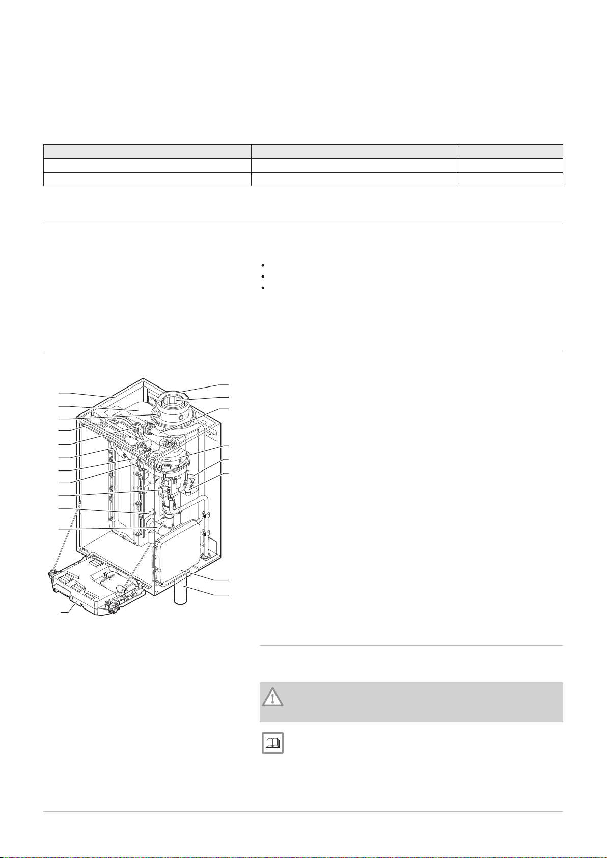
3.2 Main components
Fig.1
Main components
The Quinta Ace boiler is a high-efficiency wall-hung gas boiler with the
following properties:
High-efficiency heating.
Limited emissions of polluting substances.
Ideal choice for cascade configurations.
All Quinta Ace boiler models are supplied without a pump, but with the
required pump connection cables.
1
Casing/air box
2
Heat exchanger (CH)
3
Flue gas measuring point
4
Interior light
5
Flow sensor
6
Ionisation/ignition electrode
7
Mixing tube
8
Non-return valve
9
Combined gas valve unit
10
Return sensor
11
Air intake silencer
12
Instrument box
13
Siphon
15
Automatic air vent
16
Hydraulic pressure sensor
17
Fan
18
Supply line
19
Flue gas discharge pipe
20
Air supply
3.2.1 Circulating pump
A circulation pump is not supplied with this boiler. Take the boiler
resistance and system resistance into account when selecting a pump.
Caution
The pump may have a maximum input of 200 W. Use an auxiliary
relay for a pump with greater power.
See
Technical data, page 65
If possible, install the pump directly under the boiler on the return
connection.
AD-0000103-01
AD-0000014-02
500
min.1000
500
min.
400
350
min.
250
750
4 Before installation
12 7684359 - v.06 - 10012019
4 Before installation
4.1 Installation regulations
Warning
The installer must be registered with Gas Safe and have the
correct ACS qualifications.
Important
Practical guidelines - see the latest version.
4.2
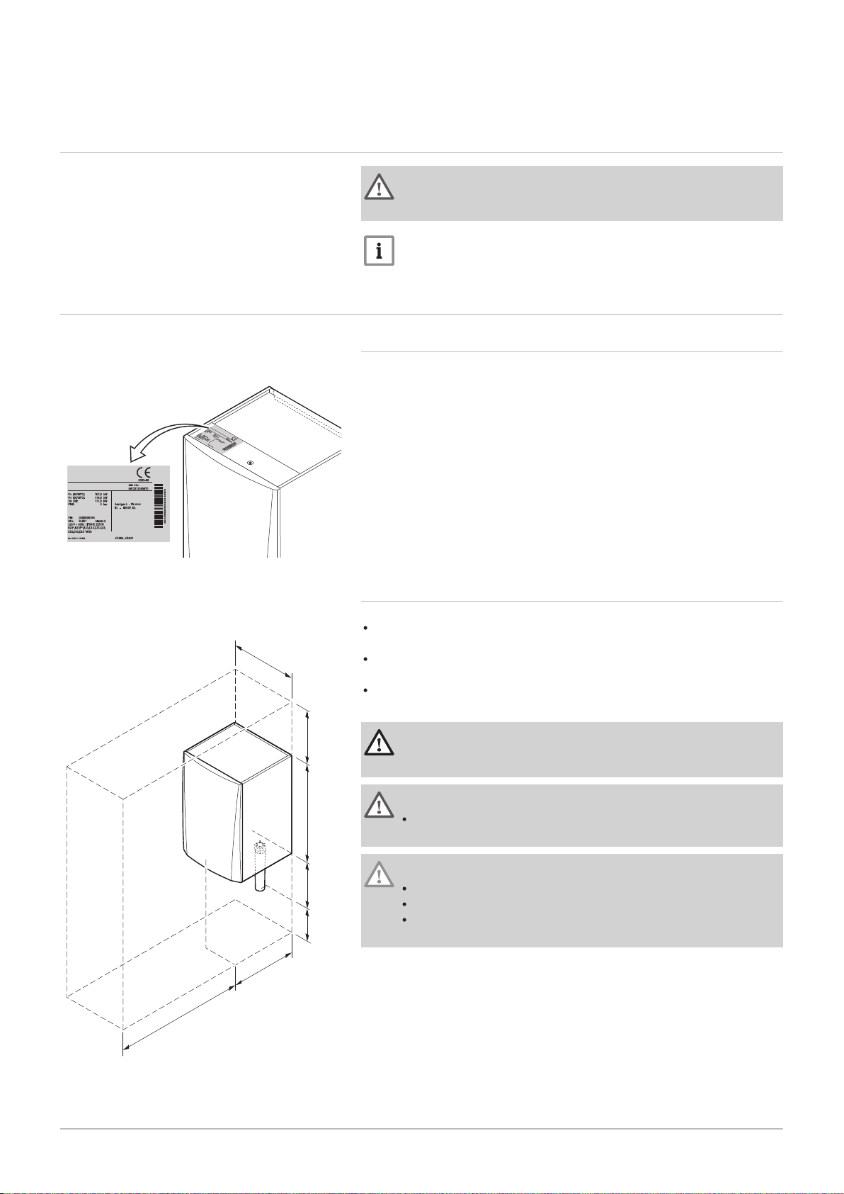
Fig.2 Position of type plate
Fig.3 Installation area
Choice of the location
4.2.1 Type plate
The type plate on top of the boiler features the boiler serial number and
important boiler specifications, for example the model and unit category.
The factory setting codes CN 1 and CN 2 are also stated on the type plate.
4.2.2 Location of the boiler
Use the guidelines and the required installation space as a basis for
determining the correct place to install the boiler.
When determining the correct installation space, take account of the
permitted position of the flue gas discharge and/or air supply outlet.
Ensure that there is sufficient space around the boiler for good access
and ease of maintenance.
Danger
It is forbidden to store, even temporarily, combustible products
and substances in the boiler or near the boiler.
Warning
Fix the appliance to a solid wall capable of bearing the weight of
the boiler when full of water and fully equipped.
Caution
The boiler must be installed in a frost-free area.
The boiler must have an earthed electrical connection.
A connection to the drain must be present for the condensate
drain close to the boiler.

4.3 Ventilation
7684359 - v.06 - 10012019 13
The installation must comply with BS 5540 (part 1 + 2), BS 6644 and
IGEM/UP/10.
4.4 Requirements for CH water connections
When fitting service shut-off valves, position the filling and drain valve,
the expansion vessel and the safety valve between the shut-off valve
and the boiler.
Carry out any welding work required at a safe distance from the boiler or
before the boiler is fitted.
For filling and tapping the boiler, install a filling and drain valve in the
system, preferably in the return.
Install an expansion vessel in the return pipe.
When installing open-vented systems, the cold feed and expansion tank
heights must comply with the requirements laid down in the Health and
Safety Executive publication PM5. The Quinta Ace boilers require a
minimum static height of 3 m (Quinta Ace 30/45/55/65/90 or 5 m ( 115).
4 Before installation
4.5
4.6
Requirements for condensate drain line
The siphon must always be filled with water. This prevents flue gases
from entering the room.
Never seal the condensate drain.
The drain pipe must slope down at least 30 mm per metre, the maximum
horizontal length is 5 metres.
Condensed water must not be discharged into a gutter.
Requirements for gas connection
Before starting work on the gas pipes, turn off the main gas tap.
Before installing, check that the gas meter has sufficient capacity. Take
into account the consumption of all appliances.
Notify the local energy company if the gas meter has insufficient
capacity.
Remove dirt and dust from the gas pipe.
Always perform welding work at a sufficient distance from the boiler.
We recommend installing a gas filter to prevent clogging of the gas
valve unit.
4.7 Requirements for the electrical connections
Establish the electrical connections in accordance with all local and
national current regulations and standards.
Electrical connections must always be made with the power supply
disconnected and only by qualified installers.
The boiler is completely pre-wired. Never change the internal
connections of the control panel.
Always connect the boiler to a well-earthed installation.
The wiring must comply with the instructions in the electrical diagrams.
Follow the recommendations in this manual.
Separate the sensor cables from the 230 V cables
AD-3000924-01
AD-3000925-01
AD-3000926-01
4 Before installation
14 7684359 - v.06 - 10012019
4.8 Requirements for the flue gas outlet system
4.8.1 Classification
Important
The installer is responsible ensuring that the right type of flue
gas outlet system is used and that the diameter and length are
correct.
Always use connection materials, roof terminal and/or outside
wall terminal supplied by the same manufacturer. Consult the
manufacturer for compatibility details.
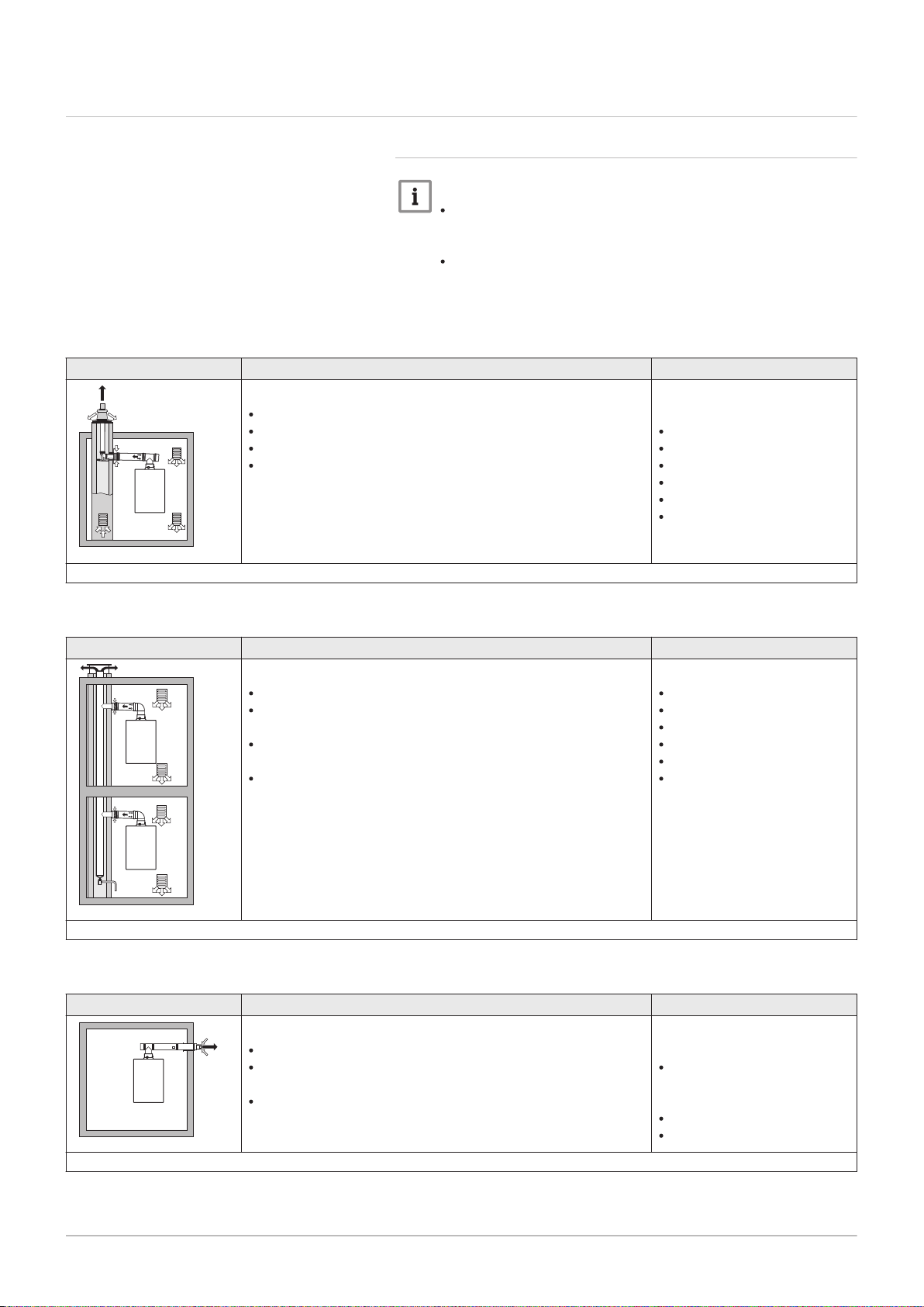
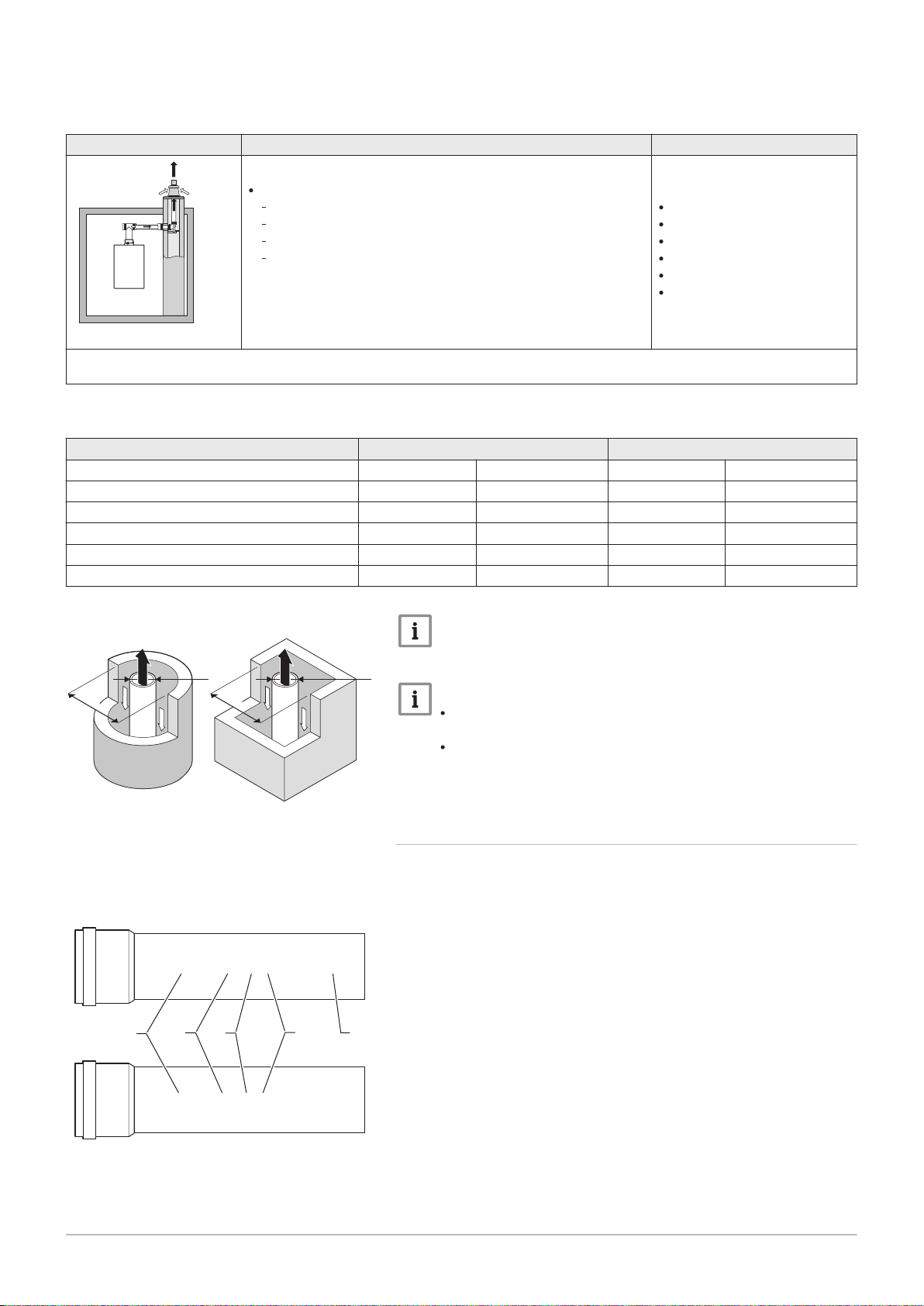
Tab.2 Type of flue gas connection: B
23P
Principle Description
Room-ventilated version
Without down-draught diverter.
Flue gas discharge via the roof.
Air from the installation area.
The IP rating of the boiler is lowered to IP20.
(1) The material must also satisfy the material property requirements from the relevant chapter.
Tab.3 Type of flue gas connection: B
33
Principle Description
Room-ventilated version
Without down-draught diverter.
Joint flue gas discharge via the roof, with guaranteed natural
draft (at all times underpressure in the joint discharge duct).
Flue gas discharge rinsed with air, air from the installation
area (special construction).
The IP rating of the boiler is lowered to IP20.
Permitted manufacturers
(1)
Connection material and roof
terminal:
Centrotherm
Cox Geelen
Muelink & Grol
Natalini
Poujoulat
Ubbink
Permitted manufacturers
(1)
Connection material:
Centrotherm
Cox Geelen
Muelink & Grol
Natalini
Poujoulat
Ubbink
(1) The material must also satisfy the material property requirements from the relevant chapter.
Tab.4 Type of flue gas connection: C
Principle Description
Room-sealed version
Discharge in the outside wall.
Air supply opening is in the same pressure zone as the dis
charge (e.g. a combined outside wall terminal).
Parallel not permitted.
13
Permitted manufacturers
Outside wall terminal and con
nection material:
Remeha, combined with con
nection material from Muelink
& Grol
Cox Geelen
Muelink & Grol
(1) The material must also satisfy the material property requirements from the relevant chapter.
(1)
AD-3000927-01
AD-3000929-02
4 Before installation
7684359 - v.06 - 10012019 15
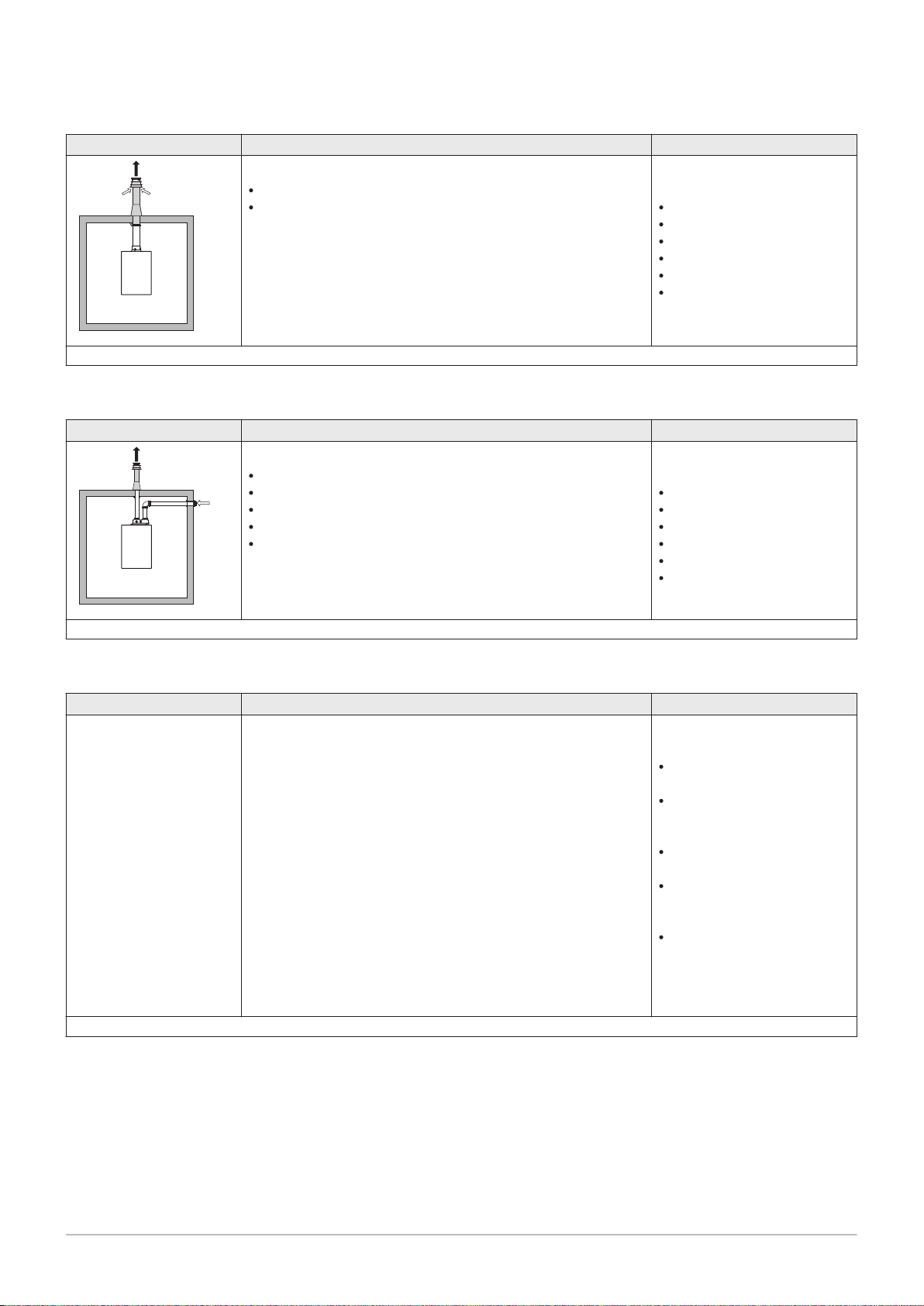
Tab.5 Type of flue gas connection: C
33
Principle Description
Room-sealed version
Flue gas discharge via the roof.
Air supply opening is in the same pressure zone as the dis
charge (e.g. a concentric roof terminal).
(1) The material must also satisfy the material property requirements from the relevant chapter.
Tab.6 Type of flue gas connection: C
53
Principle Description
Connection in different pressure zones
Closed unit.
Separate air supply duct.
Separate flue gas discharge duct.
Discharging into various pressure areas.
The air supply and the flue gas outlet must not be placed on
opposite walls.
Permitted manufacturers
(1)
Roof terminal and connection
material
Centrotherm
Cox Geelen
Muelink & Grol
Natalini
Poujoulat
Ubbink
Permitted manufacturers
(1)
Connection material and roof
terminal:
Centrotherm
Cox Geelen
Muelink & Grol
Natalini
Poujoulat
Ubbink
(1) The material must also satisfy the material property requirements from the relevant chapter.
Tab.7 Type of flue gas connection: C
63
Principle Description
This type of unit is supplied by the manufacturer without an air
supply system and flue gas system.
(1) The material must also satisfy the material property requirements from the relevant chapter.
Permitted manufacturers
(1)
When selecting the material,
please note the following:
Condensed water must flow
back to the boiler.
The material must be resist
ant to the flue gas tempera
ture of this boiler.
Maximum permissible recir
culation of 10%.
The air supply and the flue
gas outlet must not be placed
on opposite walls.
Minimum permitted pressure
difference between the air
supply and the flue gas outlet
is -200 Pa (including -100 Pa
wind pressure).
AD-3000931-01
AD-3000330-03
□
D
Ø
D
AD-3001120-01
EN 14471 - T120 P1 W 1 O50 LI E U0
EN 1856-1 - T120 P1 W VxL40045 G(xx)
1
3
2
4
5
4 Before installation
16 7684359 - v.06 - 10012019
Tab.8 Type of flue gas connection: C
Principle
(1)
Description
Room-sealed version
Air supply and flue gas discharge duct in shaft or ducted:
93
Concentric.
Air supply from existing duct.
Flue gas discharge via the roof.
Inlet opening for the air supply is in the same pressure zone
as the discharge.
Permitted manufacturers
Connection material and roof
terminal:
Centrotherm
Cox Geelen
Muelink & Grol
Natalini
Poujoulat
Ubbink
(1) See table for shaft or duct requirements.
(2) The material must also satisfy the material property requirements from the relevant chapter.
Tab.9 Minimum dimensions of shaft or duct C
93
Version (D) Without air supply With air supply
Rigid 80 mm Ø 130 mm □ 130 x 130 mm Ø 140 mm □ 130 x 130 mm
Rigid 100 mm Ø 160 mm □ 160 x 160 mm Ø 170 mm □ 160 x 160 mm
Rigid 150 mm Ø 200 mm □ 200 x 200 mm Ø 220 mm □ 220 x 220 mm
Concentric 80/125 mm Ø 145 mm □ 145 x 145 mm Ø 145 mm □ 145 x 145 mm
Concentric 100/150 mm Ø 170 mm □ 170 x 170 mm Ø 170 mm □ 170 x 170 mm
Concentric 150/200 mm Ø 270 mm □ 270 x 270 mm - -
(2)
Fig.4 Minimum dimensions of shaft or
duct C
93
Fig.5 Sample string
Important
The shaft must comply with the air density requirements of the
local regulations.
Important
Always clean shafts thoroughly when using lining pipes and/or
an air supply connection.
It must be possible to inspect the lining duct.
4.8.2 Material
Use the string on the flue gas outlet material to check whether it is suitable
for use on this appliance.
1
EN 14471 of EN 1856–1: The material is CE approved according to
this standard. For plastic this is EN 14471, For aluminium and
stainless steel this is EN 1856-1.
2
T120: The material has temperature class T120. A higher number
is also allowed, but not lower.
3
P1: The material falls into pressure class P1. H1 is also allowed.
4
W: The material is suitable for draining condensation water
(W=’wet’). D is not allowed (D=’dry’).
5
E: The material falls into fire resistance class E. Class A to D are
also allowed, F is not allowed. Only applicable to plastic.

Warning
AD-3000962-01
ød
1
L
1
øD
1
7684359 - v.06 - 10012019 17
The coupling and connection methods may vary depending on
the manufacturer. It is not permitted to combine pipes, coupling
and connection methods from different manufacturers. This also
applies to roof feed-throughs and common channels.
The materials used must comply with the prevailing regulations
and standards.
Please contact us to discuss using flexible flue gas outlet
material.
Tab.10 Overview of material properties
Version Flue gas outlet Air supply
Material Material properties Material Material properties
Single-wall, rigid
(1)
Plastic
Stainless steel
Thick-walled,
aluminium
(2)
With CE marking
(2)
Temperature class T120 or
higher
Condensate class W (wet)
Plastic
Stainless steel
Aluminium
Pressure class P1 or H1
Fire resistance class E or bet
(3)
ter
(1) according to EN 14471
(2) according to EN 1856
(3) according to EN 13501-1
4 Before installation
With CE marking
Pressure class P1 or H1
Fire resistance class E or bet
(3)
ter
Fig.6 Dimensions of concentric
connection
4.8.3 Dimensions of flue gas outlet pipe
Warning
The pipes connected to the flue gas adapter must satisfy the
following dimension requirements.
d
External dimensions of flue gas outlet pipe
1
D
External dimensions of air supply pipe
1
L
Length difference between flue gas outlet pipe and air supply pipe
1
Tab.11 Dimensions of pipe
d1 (min-max) D1 (min-max)
(1)
L
(min-max)
1
80/125 mm 79.3 - 80.3 mm 124 - 125.5 mm 0 - 15 mm
100/150 mm 99.3 - 100.3 mm 149 - 151 mm 0 - 15 mm
(1) Shorten the inner pipe if the length difference is too great.
4.8.4 Length of the air and flue gas pipes
The maximum length of the flue gas outlet and air supply channel vary
depending on the appliance type; consult the relevant chapter for the
correct lengths.
Important
When using bends, the maximum chimney length (L) must be
shortened according to the reduction table.
For adaptation to another diameter use approved transitions
The boiler is also suitable for longer chimney lengths and
diameters other than those specified in the tables. Contact us
for more information.
AD-0000028-02
L =
AD-0000029-02
L =
4 Before installation
18 7684359 - v.06 - 10012019
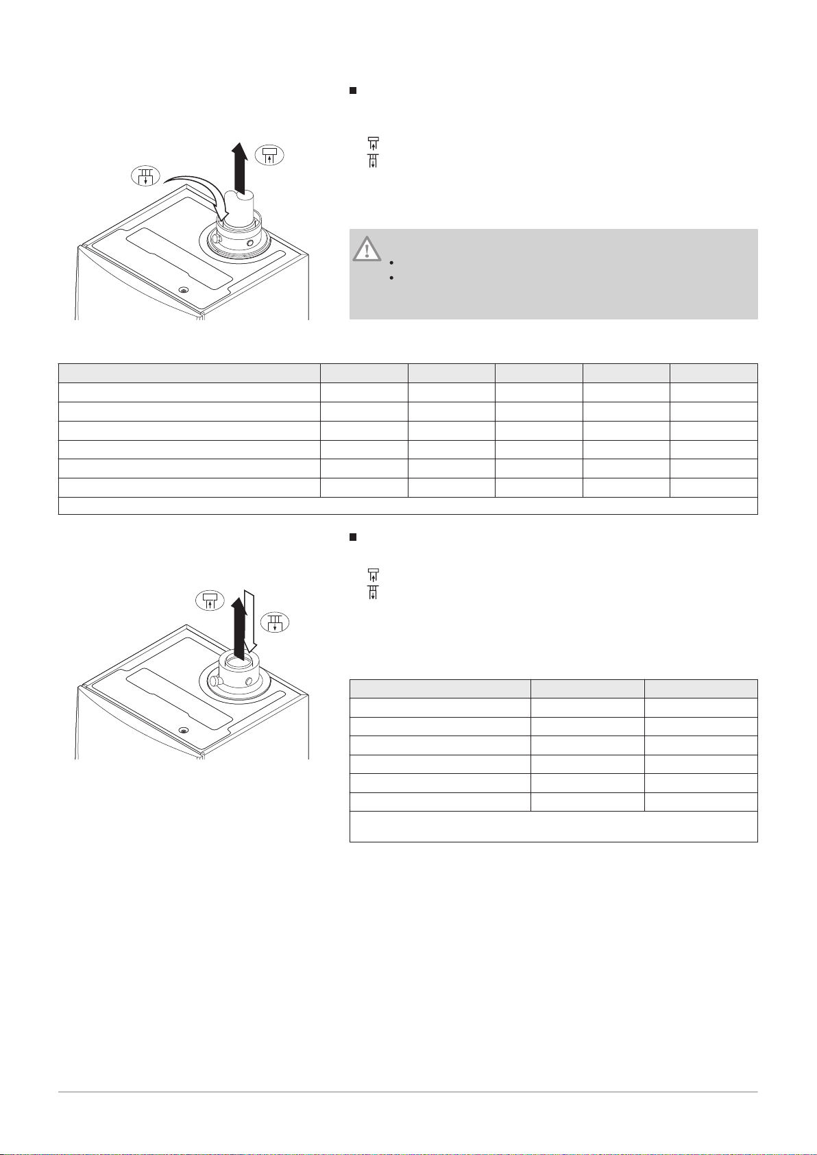
Fig.7 Room-ventilated version
Room-ventilated model (B
L
Length of the flue gas outlet channel to roof feed-through
23P
, B33)
Connecting the flue gas outlet
Connecting the air supply
With a room-ventilated version, the air supply opening stays open; only the
flue gas outlet opening is connected. This will ensure that the boiler
obtains the necessary combustion air directly from the installation area.
Caution
The air supply opening must stay open.
The installation area must be equipped with the necessary air
supply openings. These openings must not be obstructed or
shut off.
Tab.12 Maximum length (L)
Diameter
(1)
Quinta Ace 30 33 m 40 m 40 m
Quinta Ace 45 39 m
Quinta Ace 55 16 m 26 m 39 m
80 mm 90 mm 100 mm 110 mm 130 mm
40 m
40 m
(1)
40 m
(1)
40 m
40 m
Quinta Ace 65 11 m 17 m 26 m 40 m
Quinta Ace 90 10 m 16 m 24 m 40 m
Quinta Ace 115 8 m 13 m 19 m 38 m
(1) Retaining the maximum chimney length it is possible to use an extra 5 x 90º or 10 x 45º elbows.
(1)
(1)
(1)
40 m
40 m
40 m
40 m
40 m
40 m
(1)
(1)
(1)
(1)
(1)
(1)
Fig.8 Room-sealed version (concentric)
Room-sealed model (C13, C33, C63, C93)
Connecting the flue gas outlet
Connecting the air supply
With a room-sealed version, both the flue gas outlet and the air supply
openings are connected (concentrically).
Tab.13 Maximum chimney length (L)
Diameter
(1)
Quinta Ace 30 20 m 20 m
Quinta Ace 45 20 m
Quinta Ace 55 8 m
Quinta Ace 65 4 m 18 m
Quinta Ace 90 4 m 17 m
Quinta Ace 115 - 13 m
(1) Retaining the maximum chimney length it is possible to use an extra 5 x 90º
or 10 x 45º elbows.
80/125 mm 100/150 mm
(1)
20 m
(1)
20 m
Connection in different pressure areas (C53)
AD-0000030-02
= L +
7684359 - v.06 - 10012019 19
4 Before installation
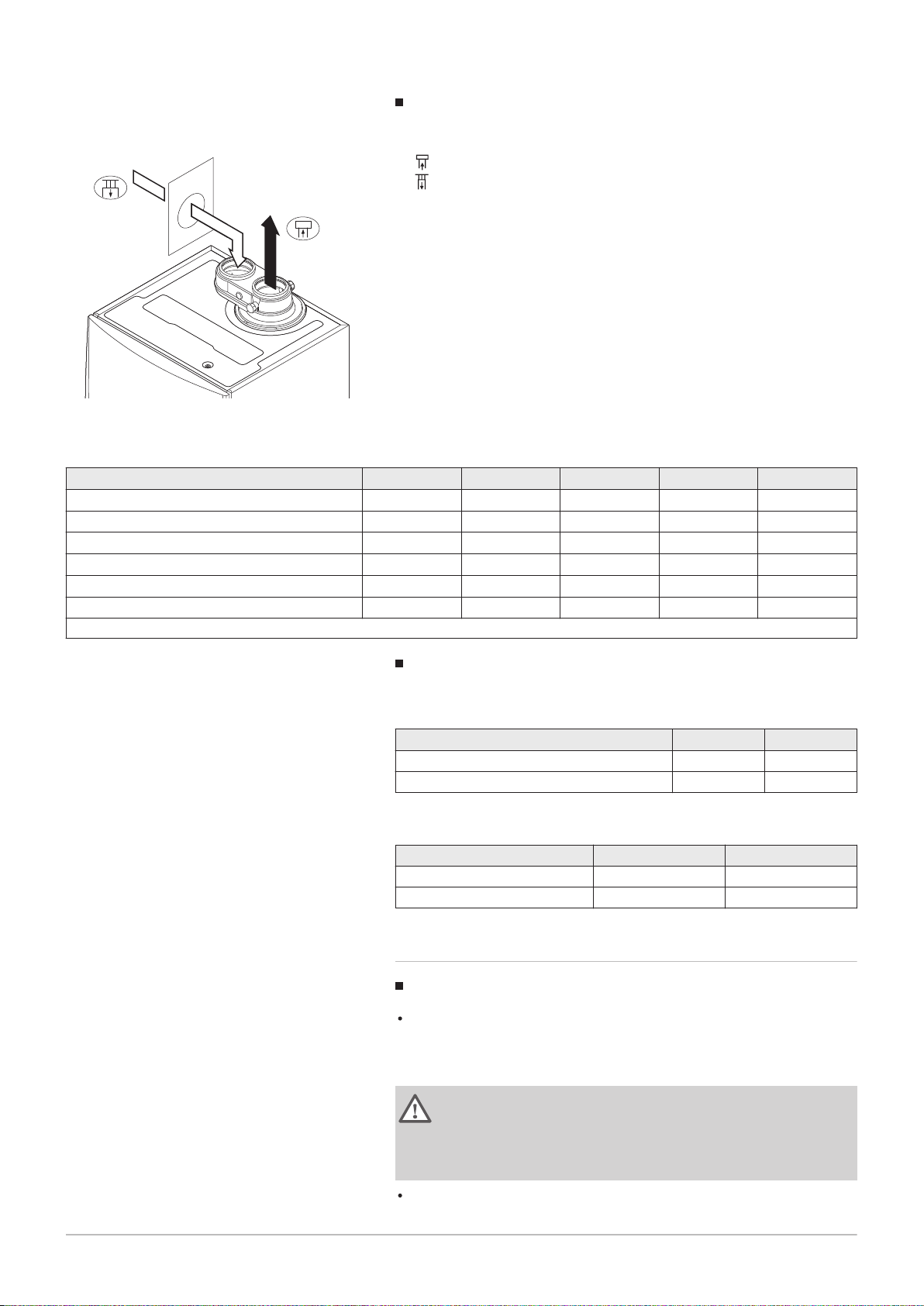
Fig.9
Different pressure areas
L
Total length of the flue gas outlet and air supply duct
Connecting the flue gas outlet
Connecting the air supply
An 80/80 or 100/100 mm flue gas adapter (accessory) must be fitted for
this connection.
Combustion air supply and flue gas discharge are possible in different
pressure areas and semi-CLV systems, with the exception of the coastal
area. The maximum permitted height difference between the combustion
air supply and the flue gas outlet is 36 m.
Tab.14 Maximum length (L)
Diameter
(1)
Quinta Ace 30 17 m 29 m 40 m
Quinta Ace 45 29 m 40 m
80 mm 90 mm 100 mm 110 mm 130 mm
40 m
(1)
40 m
40 m
Quinta Ace 55 9 m 17 m 27 m 40 m
Quinta Ace 65 5 m 10 m 16 m 34 m
Quinta Ace 90 - - 17 m 37 m
Quinta Ace 115 - - 14 m 31 m
(1) Retaining the maximum chimney length it is possible to use an extra 5 x 90º or 10 x 45º elbows.
(1)
(1)
40 m
40 m
40 m
40 m
40 m
40 m
(1)
(1)
(1)
(1)
(1)
(1)
Reduction table
Tab.15 Pipe reduction for each element used (parallel)
Diameter 80 mm 100 mm
45° bend 1.2 m 1.4 m
90° bend 4.0 m 4.9 m
Tab.16 Pipe reduction for each element used (concentric)
Diameter 80/125 mm 100/150 mm
45° bend 1.0 m 1.0 m
90° bend 2.0 m 2.0 m
4.8.5 Additional guidelines
Installation
For installing the flue gas outlet and air supply materials, refer to the
instructions of the manufacturer of the relevant material. After
installation, check at least all flue gas outlet and air supply parts for
tightness.
Warning
If the flue gas outlet and air supply materials are not installed in
accordance with the instructions (e.g. not leak-proof, not correctly
bracketed), this can result in dangerous situations and/or physical
injury.
Make sure that the flue gas outlet pipe towards the boiler has a sufficient
gradient (at least 50 mm per metre) and that there is a sufficient

4 Before installation
20 7684359 - v.06 - 10012019
condensate collector and discharge (at least 1 m before the outlet of the
boiler). The bends used must be larger than 90° to guarantee the
gradient and a good seal on the lip rings.
Condensation
Direct connection of the flue gas outlet to structural ducts is not
permitted because of condensation.
If condensate from a plastic or stainless steel pipe section can flow back
to an aluminium part in the flue gas outlet, this condensate must be
discharged via a collector before it reaches the aluminium.
Newly installed aluminium flue gas pipes with longer lengths can
produce relatively larger quantities of corrosion products. Check and
clean the siphon more often in this case.
Important
Contact us for more information.
4.9
Water quality and water treatment
4.10 Water flow in process heat
The quality of the CH water must comply with certain limit values, which
can be found in our Water quality instructions. The guidelines in these
instructions must be followed at all times.
In many cases, the boiler and central heating system can be filled with
normal tap water and water treatment will not be necessary.
In process heat applications (for example pasteurisation and drying and
washing processes), the boiler is being used for industrial purposes and
not for central heating. With process heat, the nominal flow (at ΔT 20°C) in
the primary CH circuit must be guaranteed. The flow in the secondary
circuit may vary.
To ensure that this is the case, a flow rate sensor can be fitted, which
locks out the boiler if the flow falls below a specified level (due to a
defective pump or valve, for example).
For this application, adjust the following parameters:
Set parameter DP140 to Process heat .
Set parameters DP005 and DP070 to the required value for this
installation.
If using a DHW sensor; set parameters DP034 and DP006 to the
required value for this installation.
Important
The service life of the boiler may be reduced if it is used for
process heat applications.
4.11
Increasing standard ΔT setting
In some cases, the standard ΔT setting of the boiler will need to be
increased, for example in systems with:
underfloor heating
air heating
district heating
a heat pump.

4 Before installation
7684359 - v.06 - 10012019 21
Tab.17 Increasing standard ΔT setting
Boiler type ΔT setting
Quinta Ace 30
Quinta Ace 45
The standard ΔT setting of 25K can be increased to
a maximum of 40K.
Quinta Ace 55
Quinta Ace 65
Quinta Ace 90
Quinta Ace 115 The standard ΔT setting of 20K can be increased to
a maximum of 35K.
Increase the ΔT setting using parameter GP021. When increasing the ΔT,
the control unit limits the flow temperature to a maximum of 80 °C.
Important
With the increased ΔT setting, the Service Tool will use a substatus to indicate that the limited flow temperature is active.
Prevent the boiler from locking out and ensure a minimal water
circulation by using a bypass or low-loss header.
If a PWM-controlled central heating-pump is controlled by the
boiler control unit, set parameter PP014 to 2.
AD-0000018-02
2
1
5
4
3
5 Installation
22 7684359 - v.06 - 10012019
5 Installation
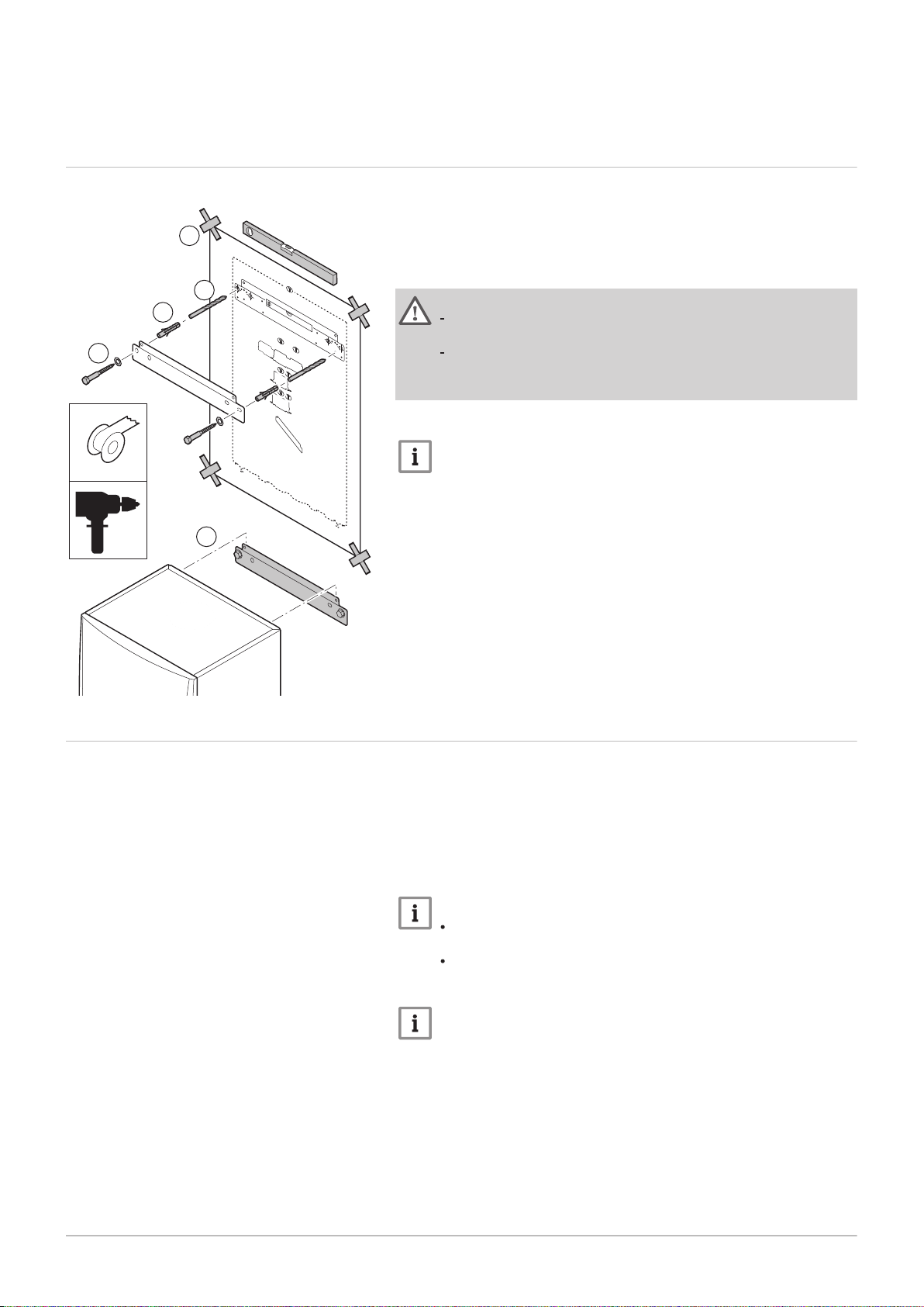
5.1 Positioning the boiler
Fig.10 Mounting the boiler
The fitting bracket on the back of the casing can be used to mount the
boiler directly on the suspension bracket.
The boiler is supplied with a mounting template.
1. Attach the mounting template of the boiler to the wall using adhesive
tape.
Warning
Use a level to check whether the mounting template is hanging
perfectly horizontally.
Protect the boiler against building dust and cover the connection
points for the flue gas outlet and air supply. Only remove this
cover to assemble the relevant connections.
2. Drill 2 holes of Ø 10 mm.
Important
The extra fixing holes in the suspension bracket are intended for
use in the event that one of the two holes is not suitable for the
correct fastening of the plug.
3. Fit the Ø 10 mm plugs.
4. Remove the mounting template.
5. Attach the suspension bracket to the wall with the Ø 10 mm bolts
supplied.
6. Mount the boiler on the suspension bracket.
5.2 Rinsing the system
The installation must be cleaned and flushed in accordance with BS 7593
(2006) and BSRIA BG 33/2014.
Before a new boiler can be connected to an existing or new system, the
entire system must be thoroughly cleaned and flushed. This step is
absolutely crucial. The flushing helps to remove residue from the
installation process (weld slag, fixing products etc.) and accumulations of
dirt (silt, mud etc.)
Important
Flush the system with a volume of water equivalent to at least
three times the volume of the system.
Flush the DHW pipes with at least 20 times the volume of the
pipes.
Important
Due to the presence of an aluminium heat exchanger, suitable
chemicals and the correct use of these chemicals should be
discussed with specialist water treatment companies.
5.3 Connecting the heating circuit
AD-4100110-01
1
2
4
5
4
3
AD-0000024-02
4
1
2
3
7684359 - v.06 - 10012019 23
5 Installation
Fig.11 Connecting the CH flow and CH
return
1. Remove the dust cap from the CH flow connection at the bottom
of the boiler.
2. Fit the outlet pipe for CH water to the CH flow connection.
3. Remove the dust cap from the CH return connection at the
bottom of the boiler.
4. Fit the inlet pipe for CH water to the CH return connection.
5. Install the pump in the CH return pipe (if applicable).
For more information, see
Connecting the PWM pump, page 29
Connecting the standard pump, page 30
5.4 Connecting the condensate discharge pipe
Fig.12 Connecting the condensate
discharge pipe
1. Fit a plastic drain pipe of Ø 32 mm or larger, terminating in the drain.
2. Insert the flexible condensate drain hose into the pipe.
3. Fit a stench-trap or siphon in the drain pipe.
4. Fit the siphon.

AD-0000025-02
2
3
4
1
AD-0000034-01
80/125 mm
100/150 mm
S
5 Installation
24 7684359 - v.06 - 10012019
5.5 Gas connection
Fig.13 Connecting the gas pipe
5.6
Air supply/flue gas outlet connections
Fig.14 Connecting the flue gas outlet and
air supply
1. Remove the dust cap from the gas supply pipe at the bottom of
the boiler.
2. Fit the gas supply pipe.
3. Fit a gas tap in this pipe, directly underneath the boiler (within 1
metre).
4. Fit the gas pipe to the gas tap.
Important
The gas tap must always be accessible
5.6.1 Connecting the flue gas outlet and air supply
S Insertion depth 25 mm
1. Connect the flue gas outlet pipe and the air supply pipe to the boiler.
2. Fit the subsequent flue gas outlet pipes and air supply pipes in
accordance with the manufacturer's instructions.
5.7 Electrical connections
Caution
The pipes must not be resting on the boiler.
Fit the horizontal parts sloping down towards the boiler, with a
gradient of 50 mm per metre.
5.7.1 Control unit
The table gives important connection values for the control unit.
Tab.18 Connection values for control unit
Supply voltage 230 VAC/50 Hz
Main fuse value F1 (230 VAC) 2.5 AT
Fan 230 VAC

AD-4000065-01
90 º
2
6
4
3
2
1
5
9
8
7
10
5 Installation
7684359 - v.06 - 10012019 25
Danger of electric shock
The following components of the boiler are connected to a 230 V
power supply:
Electrical connection to circulating pump.
Electrical connection to gas combination block.
Electrical connection to fan.
Control unit.
Ignition transformer.
Power supply cable connection.
The boiler has a three-wire mains lead (lead length 1.5 m) and is suitable
for a 230 VAC/50 Hz power supply with a phase/neutral/earth system. The
boiler is not phase sensitive. The power supply cable is connected to the
X1 connector. A spare fuse can be found in the housing of the control unit.
Caution
Always order a replacement mains lead from Remeha. The
power supply cable should only be replaced by Remeha , or by
an installer certified by Remeha .
The boiler switch must be easily accessible at all times.
The boiler has several control, protection and regulation connection
options. The standard PCB can be extended with optional PCBs.
Fig.15 Access to the connectors
5.7.2 Access to the connectors
The following is installed in the instrument box:
the standard PCB CB-03 with connector X-03.
the IF-01 PCB with connector X4 and X5
Various thermostats and regulators can be connected to this.
Access to the connectors:
1. Unscrew the two screws located under the front housing by a quarter
turn and remove the front housing.
2. Press the clips on the sides of the instrument box inwards slightly.
3. Tilt the instrument box forwards.
4. Press the clip on the side of the instrument box flap inwards slightly.
5. Open the instrument box flap.
The connector X-03 for the CB-03 PCB is now accessible
6. Open the instrument box by releasing the clips (4x) using a
screwdriver.
The connectors X4 and X5 for the IF-01 PCB are now accessible.
7. Guide the cables from the regulator or the thermostat through the
round grommet(s) on the boiler's bottom plate.
8. Guide the relevant connection cable(s) through the instrument box via
the cable ducts provided.
9. Undo the strain relief clip(s) and feed the cable(s) underneath.
10. Connect the cables to the appropriate terminals on the connector.
11. Press the strain relief clip(s) firmly into place.
12. Close the instrument box.

AD-4100101-02
T
out
BL RL
R-Bus
OT
Tdhw
AD-4100102-02
ToutBL RL
R-Bus
Tk
Tdhw
AD-4100103-02
ToutBL RL
R-Bus
TvTk
Tdhw
5 Installation
26 7684359 - v.06 - 10012019
Fig.16 Connecting modulating thermostat
5.7.3 Connection options for the standard PCB
General
Various thermostats and regulators can be connected to the standard
PCB.
Connecting modulating thermostat
The boiler is fitted with an R-Bus connection as standard. This connection
is also compatible with OpenTherm. This enables the user to connect
modulating OpenTherm thermostats (such as iSense) or R-Bus
thermostats (such as eTwist) without any further adjustments being made
to the appliance. The boiler is also suitable for OpenTherm Smart Power.
1. In the case of a room thermostat: install the thermostat in a reference
room.
2. Connect the two-wire cable for the thermostat to the R-Bus terminals
for the connector. It does not matter which wire is connected to which
cable clamp.
Important
If the tap water temperature can be set on the OpenTherm
thermostat, the boiler will supply this temperature, with the value
set in the boiler as a maximum.
Fig.17 Connecting the on/off thermostat
Fig.18 Connecting the frost thermostat
Connecting the on/off thermostat
The boiler is suitable for connection to a two-wire on/off ambient
thermostat (Tk).
1. Install the (power stealing) thermostat in a reference room.
2. Connect the two-wire cable for the thermostat to the R-Bus terminals
for the connector. It does not matter which wire is connected to which
cable clamp.
Frost protection combined with on/off thermostat
When an on/off thermostat is used, the pipes and radiators in a frostsensitive room can be protected by a frost thermostat. The radiator valve
in the frost-sensitive room must be open.
1. Place a frost thermostat (Tv) in a frost-sensitive room (e.g. a garage).
2. Connect the frost thermostat (Tv) parallel to the on/off thermostat (Tk)
on the R-Bus terminals for the connector.
Warning
If a Remeha eTwist or OpenTherm thermostat is used, a frost
thermostat cannot be connected in parallel to the R-Bus terminals.
In that case, implement frost protection of the central heating
system in combination with an outside sensor.
For more information, see
Additional documentation, page 10

Fig.19 Connecting an outside sensor
AD-4100109-02
BL RL outT
R-Bus
Tdhw
AD-4100109-02
BL RL outT
R-Bus
Tdhw
AD-0000871-02
20
100-20
-10
15
30
45
60
75
90
0,5
1,0
1,5
2,0
2,5
F
3
2
1
7684359 - v.06 - 10012019 27
Fig.20 Connecting an outside sensor
5 Installation
Frost protection combined with outside sensor
The central heating system can also be protected against frost in
combination with an outside sensor. The radiator valve in the frostsensitive room must be open.
1. Connect the outside sensor to the Tout terminals of the connector.
The frost protection works as follows with an outside sensor:
If the outside temperature in lower than -10°C: heat demand from the
boiler.
If the outside temperature is higher than -10°C: no heat demand from
the boiler.
Important
The outside temperature before the start of frost protection can be
changed with parameter AP080 (as mentioned above the factory
setting is -10).
Connecting an outside sensor
An outside sensor can be connected to the Tout terminals of the connector
(accessory). In the event of an on/off thermostat, the boiler will regulate
the temperature using the set point of the internal heating curve (F).
Various parameter settings can be used to change the internal heating
curve.
1. Connect the plug from the outside sensor to the Tout connector.
Fig.21 Internal heating curve
Outside sensor data
Various outside sensors can be used. Use below mentioned sensors or
sensors with identical characteristics:
AF60 = NTC 470 Ω/25°C
QAC34 = NTC 1000 Ω/25°C
Select the outside sensor with parameter AP056.
Setting the heating curve
Various parameter settings can be used to change the internal heating
curve.
F
Heating curve
1
Heating curve set point (maximum flow temperature)
parameter CP010 / CP000
2
Heating curve comfort base point
parameter CP210
3
Heating curve steepness
parameter CP230
Outside temperature (Tout)
Flow temperature (Ta)
Important
An OpenTherm controller can also use this outside sensor. In that
case, the desired internal heating curve must be set on the
controller.

AD-4100104-02
ToutBL RL
R-Bus
Tdhw
AD-3001303-01
RL
5 Installation
28 7684359 - v.06 - 10012019
Tab.19 Internal heating curve settings
Comfort base point
(°C)
Steepness
(parameter CP230)
Ta (°C)
(where Tout = –10°C)
(parameter CP210)
15 0.5 30
15 1.0 45
15 1.5 60
15
2.0
(1)
75
15 2.5 90
15 3.0
(1) See sample drawing
(2) Flow temperature is cut off at Ta (max) = parameter CP010 / CP000
105
(2)
Blocking input
Fig.22
Blocking input
Fig.23 Release input
The boiler has a blocking input (Normally Closed contact). This input
relates to the BL terminals of the connector.
If this contact is opened, the boiler will be blocked or locked out.
Change the function of the input with parameter setting AP001. This
parameter has the following 3 configuration options:
Complete blocking: no frost protection with the outside sensor and no
boiler frost protection (pump does not start and burner does not start)
Partial blocking: boiler frost protection (pump starts when the
temperature of the heat exchanger is < 6°C and the burner starts when
the temperature of the heat exchanger is < 3°C)
Lock out: no frost protection with outside sensor and partial boiler frost
protection (pump starts when the temperature of the heat exchanger is <
6°C, the burner does not start when the temperature of the heat
exchanger is < 3°C).
Important
First remove the bridge if this input is used.
Warning
Only suitable for potential-free contacts.
Release input
The boiler has a release input (Normally Open contact). This input relates
to the RL terminals of the connector.
If this contact is closed before there is a heat demand, the boiler will be
blocked after a waiting time. Change the waiting time of the input with
parameter setting AP008.
If this contact is closed during a heat demand, the boiler will be blocked
instantly.
Warning
Only suitable for potential-free contacts.
Connecting the calorifier sensor/thermostat
A calorifier sensor or thermostat can be connected to the Tdhw terminals
of the connector.

AD-4000096-01
BL RL
R-Bus
TdhwTout
AD-4000094-01
2
3
X81
X112
4
1
5
6
X81
X81
X112
X112
5 Installation
7684359 - v.06 - 10012019 29
Fig.24 Connecting the calorifier sensor/
thermostat
Fig.25 Connecting the power supply cable
1. Connect the plug from the calorifier sensor or calorifier thermostat to
the Tdhw connector.
Domestic hot water sensor data
Various domestic hot water sensors can be used. Use below mentioned
sensor or sensors with identical characteristics:
NTC 10 kΩ/25°C
Connecting the PWM pump
The energy-efficient modulating pump must be connected to the standard
control PCB. To do this, proceed as follows:
1. Connect the power supply cable and the cable for the PWM signal to
the pump.
2. Remove the grommet from the opening in the middle of the base of
the boiler.
3. Pass the pump power supply cable through the base of the boiler and
seal the opening by tightening the bayonet fitting to the cable.
4. Pass the PWM cable from the pump through one of the grommets on
the right in the base of the boiler.
5. Connect the X81 pump power supply cable to the X81 cable that runs
along the cable duct to the left of the instrument box.
6. Connect the X112 pump PWM cable to the X112 cable that runs along
the cable duct to the right of the instrument box.
Important
The pump's various settings can be adjusted using the
parameters PP014, PP016, PP017 and PP018.

AD-4000093-01
X81
X81
X81
2
3
1
4
AD-0000054-01
Status 0-10 0-10
Nc NoC
Nc No OTm 0 + 0 +C
OTm 0 + 0 +
X5
X4
X1
IF-01
%
1
2
5 Installation
30 7684359 - v.06 - 10012019
Fig.26 Connecting the power supply cable
Connecting the standard pump
The pump must be connected to the standard control PCB. To do this,
proceed as follows:
1. Connect the X81 power cable supplied with the boiler to the pump.
2. Remove the grommet from the opening in the middle of the base of
the boiler.
3. Pass the pump X81 cable through the base of the boiler and seal the
opening by tightening the bayonet fitting to the cable.
4. Connect the X81 pump cable to the X81 cable that runs along the
cable duct to the left of the instrument box
5.7.4
Additional control PCBs
Connection options for the extension PCB IF-01
Fig.27 IF-01 PCB
The IF-01 extension PCB is pre-installed in the instrument box as
standard.
Caution
Do not connect a frost thermostat or room thermostat to the boiler
if using the 0–10 V control PCB.
Connecting the status relay (Nc)
If the boiler locks out, a relay is de-energised and the alarm can be
transmitted via a potential-free contact (maximum 230 V, 1 A) on terminals
Nc and C of the connector.
Connection (OTm)
The interface uses OpenTherm to communicate with the boiler control
unit. To make this possible, the OTm connection must be connected to the
OpenTherm input of the boiler control unit.OTm
Analogue input (0-10 V)
A choice can be made with this control between control based on
temperature or heat output. The two controls are described briefly below.
1. Connect the input signal to terminals 0–10 of the connector.

Tab.20 Temperature-based control (°C)
AD-0000055-01
1
2
%
2 2
AD-0000056-01
1
2
%
1 1
7684359 - v.06 - 10012019 31
Jumper 2 Input signal (V) Temperature °C Description
0–1.5 0–15 Boiler off
1.5–1.8 15–18 Hysteresis
1.8–10 18–100 Desired temperature
5 Installation
Fig.28 Switch jumper (2)
Fig.29 Switch jumper (1)
The 0–10 V signal controls the boiler supply temperature. This control
modulates on the basis of flow temperature. The output varies between
the minimum and maximum value on the basis of the flow temperature set
point calculated by the controller.
A jumper (2) on the interface is used to select either temperature-based
control ( ) or output-based control (%).
Tab.21 Control based on heat output
Jumper 2 Input signal (V) Heat output (%) Description
(1)
0–2.0
%
2.0–2.2
2.0–10
(1) Dependent on the minimum modulation depth (set speeds, standard 20%)
(1)
(1)
0–20 Boiler off
20–22 Hysteresis
20–100 Desired heat output
The 0–10 V signal controls the boiler output. This control modulates on the
basis of the heat output. The minimum output is linked to the boiler's
modulation depth. The output varies between the minimum and maximum
value on the basis of the value defined by the controller.
Analogue output (0–10 V)
This feedback can be based on temperature or heat output. The two
controls are described briefly below.
A jumper (1) on the interface is used to select either temperature ( ) or
output (%).
Tab.22 Temperature message
Jumper 1 Output signal (V) Temperature °C Description
0.5 – Alarm
1–10 10–100 Supplied tempera
ture
Tab.23 Output message
Jumper 2 Output signal (V) Heat output (%) Description
0 0–15 Boiler off
0.5 15–20 Alarm
%
(1)
2.0–10
(1) Dependent on the minimum modulation depth (set speeds, standard 20%)
20–100 Supplied heat output

AD-3000932-01
3
4
1
6
2
5
AD-3001157-01
All OK
Error Status
22/02/2018 11:20 Home Screen
i
i
All OK
2
5
43
1
6 Before commissioning
32 7684359 - v.06 - 10012019
6 Before commissioning
6.1 Control panel description
6.1.1 Description of the components
Fig.30 Components of the control panel
1 Rotary knob to select a tile, menu or setting
2
Button to confirm the selection
3
Back button to return to the previous level or previous menu
4
Menu button to return to the main menu
5 Display
6 LED for status indication:
continuous green = normal operation
flashing green = warning
continuous red = shutdown
flashing red = lockout
For more information, see
Additional documentation, page 10
6.1.2 Description of the home screen
This screen is shown automatically after start-up of the appliance. The
control panel goes automatically in standby mode (black screen) if the
screen is not touched for 5 minutes. Press one of the buttons on the
control panel to activate the screen again.
You can navigate from any menu to the home screen by pressing the back
button
The tiles on the home screen provide quick access to the corresponding
menus. Use the rotary knob to navigate to the menu of your choice and
press the button to confirm the selection.
for several seconds.
Fig.31 Icons on home screen
1 Tiles: the selected tile is highlighted
2 Date and time | Name of the screen (actual position in the menu)
3 Information about the selected tile
4 Error indicator (only visible if an error has been found)
5 Icon showing the navigation level:
: Chimney sweeper level
: User level
: Installer level
The installer level is protected by an access code. When this
level is active, the status of the tile [
] changes from Off into
On.
6.1.3 Description of the main menu
You can navigate from any menu directly to the main menu by pressing
the menu button . The number of accessible menus depends on the
access level (user or installer).

AD-3000935-01
A B
C
6 Before commissioning
7684359 - v.06 - 10012019 33
Fig.32 Items in the main menu
Tab.26 Icons
User level
Installer level
Chimney sweeper level System settings
Service Water pressure
Timer program DHW 1
Temporary overwrite of the timer program DHW 2
Holiday program DHW boost on
Manual Gas boiler
Energy-saving mode
Frost protection Burner on
Central heating on Outside temperature sensor
All zones (groups) DHW tank
Living room
Kitchen
Bedroom
Study
Cellar
(1) Adjustable icon for heating zone
(1)
(1)
(1)
(1)
(1)
A Date and time | Name of the screen (actual position in the menu)
B Available menus
C Brief explanation of the selected menu
Tab.24 Available menus for the user
Description Icon
System Settings
Version Information
Tab.25 Available menus for the installer
Description Icon
Installation Setup
Commissioning Menu
Advanced Service Menu
Error History
System Settings
Version Information
Meaning of the icons in the display
Information
Error display
Burner output level (1 to 5 bars, with each bar repre
senting 20% output)
Solar calorifier
Cascade
Pump
Three-way valve

AD-0000086-01
1
3
2
AD-0000066-02
C C
1 2
6 Before commissioning
34 7684359 - v.06 - 10012019
6.2 Checklist before commissioning
6.2.1 Filling the siphon
Danger
The siphon must always be sufficiently filled with water. This
prevents flue gases from entering the room.
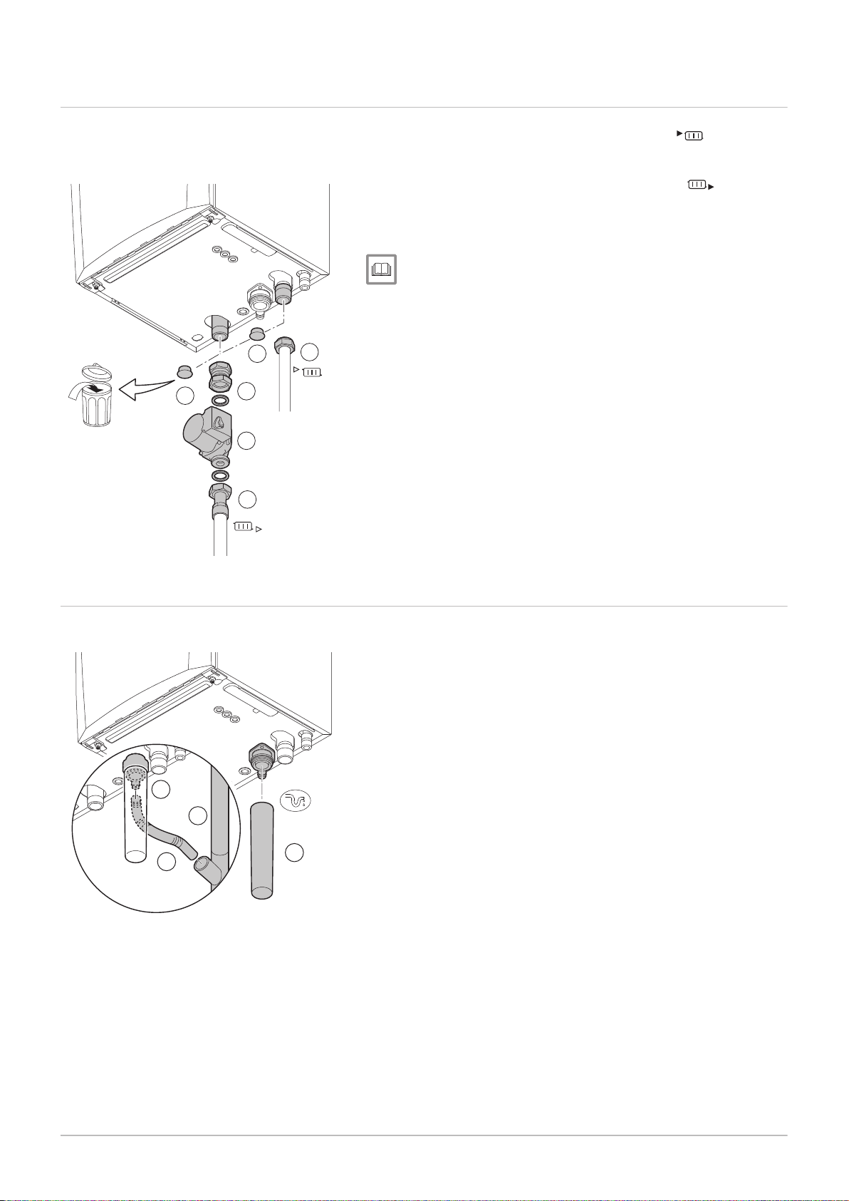
Fig.33
Filling the siphon
1. Remove the siphon.
2. Fill the siphon up with water.
3. Fit the siphon.
Check that the siphon is securely fitted and that there are no leaks.
6.2.2 Filling the system
Caution
Before filling, open the valves on every radiator in the installation.
Fig.34 Gas valve unit measuring points C
Important
In order to be able to read off the water pressure from the boiler
display, the boiler must be switched on.
1. Fill the central heating system with clean tap water.
Important
The recommended water pressure is between 1.5 bar and 2 bar.
2. Check the water-side connections for tightness.
6.2.3 Gas circuit
1 Quinta Ace 30 - 45 - 55 - 65 - 90
2 Quinta Ace 115
Warning
Ensure that the boiler is switched off.
Do not put the boiler into operation if the type of gas supplied
does not conform to the approved gas types.
1. Open the main gas tap.
2. Open the boiler gas tap.
3. Unscrew the two screws located under the front housing by a quarter
turn and remove the front housing.

6 Before commissioning
7684359 - v.06 - 10012019 35
4. Check the gas inlet pressure at the measuring point C on the gas
valve unit.
Warning
The gas pressure that was measured at the measuring point C
must fall within the stated gas inlet pressure limits. See
Technical data, page 65
For authorised gas pressures, see: Unit categories, page 62
5. Vent the gas supply pipe by unscrewing the measuring point on the
gas valve unit.
6. Tighten the measuring point again when the pipe has been fully
vented.
7. Check all connections for gas tightness. The maximum allowable test
pressure is 60 mbar.
6.2.4 Hydraulic circuit
1. Check the siphon; it should be fully filled with clean water.
2. Check the water-side connections for tightness.
6.2.5
1. Check the electrical connections.
Electrical connections

AD-0000067-02
A A
1 2
7 Commissioning
36 7684359 - v.06 - 10012019
7 Commissioning
7.1 Commissioning procedure
Warning
Initial commissioning must be done by a qualified installer.
If adapting to another type of gas, e.g. propane, the boiler must
be adjusted before it is switched it on.
See
Adjusting to a different gas type, page 36
1. Open the main gas tap.
2. Open the boiler gas tap.
3. Switch the power on with the boiler's on/off switch.
The start-up program will start and cannot be interrupted. During the
program, all segments of the display are shown briefly.
4. Set the components (thermostats, control) so that heat is demanded.
Important
In the event of an error during the start-up, a message with the
corresponding code is displayed. The meaning of the error codes
can be found in the error table.
7.2 Gas settings
7.2.1 Adjusting to a different gas type
Fig.35 Position of adjusting screw A
Tab.27 Factory settings G20 (H-gas)
Code Display text Description Adjustment range 30 45 55 65 90 115
DP003 Abs. max fan
DHW
GP007 Fan RPM Max CHMaximum fan speed
GP008 Fan RPM Min Minimum fan speed
GP009 Fan RPM Start Fan speed at appliance
Maximum fan speed on
Domestic Hot Water
during Central Heating
mode
during Central Heating +
Domestic Hot Water
mode
start
1 Quinta Ace 30 - 45 - 55 - 65 - 90
2 Quinta Ace 115
The factory setting of the boiler is for operation with the natural gas group
G20 (H gas).
1000 Rpm 7000
Rpm
1400 Rpm 7000
Rpm
1400 Rpm 4000
Rpm
1000 Rpm 4000
Rpm
4100 5400 5100 5600 6300 6800
4100 5400 5100 5600 6300 6800
1550 1550 1600 1600 1600 1750
2500 2500 2500 2500 2500 2500
Warning
Only a qualified installer may carry out the following operations.
Before operating with a different type of gas, carry out the following steps.

AD-0000069-01
7 Commissioning
7684359 - v.06 - 10012019 37
Tab.28 If operating on propane
Boiler type Action
Quinta Ace 30 Rotate the adjusting screw A on the venturi 3½ turns
in a clockwise direction
Quinta Ace 45 Rotate the adjusting screw A on the venturi 4¾ turns
in a clockwise direction
Quinta Ace 55 Rotate the adjusting screw A on the venturi 6½ turns
in a clockwise direction
Quinta Ace 65 Rotate the adjusting screw A on the venturi 6½ turns
in a clockwise direction
Quinta Ace 90 Replace the current gas valve unit with the propane
gas valve unit according to the instructions supplied
with the propane conversion kit
Quinta Ace 115 Rotate the adjusting screw A in a clockwise direction
until it is closed, then:
Rotate the adjusting screw A on the gas valve unit
3½–4 turns in an anticlockwise direction
1. Adjust the fan speed (if necessary) for the gas type used according to
the table below. The setting can be changed with a parameter setting.
Tab.29 Adjustment for gas type G31 (propane)
Code Display text Description Adjustment range 30 45 55 65 90 115
DP003 Abs. max fan
DHW
GP007 Fan RPM Max CHMaximum fan speed
Maximum fan speed on
Domestic Hot Water
during Central Heating
1000 Rpm 7000
Rpm
1400 Rpm 7000
Rpm
3800 5100 4800 5400 6000 6700
3800 5100 4800 5400 6000 6700
mode
GP008 Fan RPM Min Minimum fan speed
during Central Heating +
1400 Rpm 4000
Rpm
1550 1550 1500 1600 2000 1800
Domestic Hot Water
mode
GP009 Fan RPM Start Fan speed at appliance
start
1000 Rpm 4000
Rpm
2500 3000 2500 2500 2500 3500
2. Check the setting of the gas/air ratio.
7.2.2 Checking and setting the gas/air ratio
Fig.36 Flue gas measuring point
1. Unscrew the cap from the flue gas measuring point.
2. Insert the probe for the flue gas analyser into the measurement
opening.
Warning
During measurement, seal the opening around the sensor fully.
Important
The flue gas analyser must have a minimum accuracy of
±0.25% O2/CO2.
The flue gas analyser must meet the requirements of BS 7927
or BS-EN 503793 and be calibrated according to the
manufacturer's requirements.
3. Measure the percentage of O2/CO2 in the flue gases. Take
measurements at full load and at part load.
Important
Measurements must be taken with the front casing off.

AD-3000941-02
A
B
AD-0000067-02
A A
1 2
7 Commissioning
38 7684359 - v.06 - 10012019
Fig.37 Full load test
Performing the full load test
1. Select the tile [ ].
The Change load test mode menu appears.
2. Select the test MaximumPowerCH.
A Change load test mode
B MaximumPowerCH
The full load test starts. The selected load test mode is shown in the
menu and the icon
appears in the top right of the screen.
3. Check the load test settings and adjust if necessary.
Only the parameters shown in bold can be changed.
Checking/setting values for O2/CO2 at full load
Fig.38 Position of adjusting screw A
1 Quinta Ace 30 - 45 - 55 - 65 - 90
2 Quinta Ace 115
1. Measure the percentage of O2/CO2 in the flue gases.
2. Compare the measured value with the checking values in the table.
3. If the measured value is outside of the values given in the table,
correct the gas/air ratio.
Warning
Only a qualified installer may carry out the following operations.
4. Using adjusting screw A, adjust the percentage of O2/CO2 for the gas
type being used to the nominal value. This should always be inside
the highest and lowest setting limit.
Tab.30 Checking/setting values for O2/CO2 at full load for G20 (H
gas)
Values at full load for G20 (H
O2 (%)
(1)
CO2 (%)
(1)
gas)
Quinta Ace 30 4,3 - 4,8
Quinta Ace 45 4,3 - 4,8
Quinta Ace 55 4,3 - 4,8
Quinta Ace 65 4,3 - 4,8
Quinta Ace 90 4,3 - 4,7
Quinta Ace 115 4,2 - 4,7
(1) Nominal value
(1)
(1)
(1)
(1)
(1)
(1)
9,0
9,0
9,0
9,0
9,1
9,1
(1)
- 9,3
(1)
- 9,3
(1)
- 9,3
(1)
- 9,3
(1)
- 9,3
(1)
- 9,4
Tab.31 Checking/setting values for O2/CO2 at full load for G31
(propane)
Values at full load for G31 (pro
pane)
Quinta Ace 30 4,4 - 4,9
Quinta Ace 45 4,4 - 4,9
Quinta Ace 55 4,1 - 4,6
Quinta Ace 65 4,6 - 4,9
Quinta Ace 90 4,9 - 5,2
Quinta Ace 115 4,9 - 5,4
(1) Nominal value
O2 (%)
(1)
CO2 (%)
(1)
(1)
(1)
(1)
(1)
(1)
10,5
10,5
10,7
10,5
10,3
10,2
(1)
- 10,8
(1)
- 10,8
(1)
- 11,0
(1)
- 10,7
(1)
- 10,5
(1)
- 10,5
(1)

Fig.39 Part load test
AD-3000941-02
A
B
AD-0000072-02
B B
B
1 2
7684359 - v.06 - 10012019 39
7 Commissioning
Caution
The O2 values at full load must be lower than the O2 values at
part load.
The CO2 values at full load must be higher than the CO2 values
at part load.
Performing the part load test
1. If the full load test is still running, press the button to change the
load test mode.
2. If the full load test was finished, select the tile [ ] to restart the
chimney sweep menu.
A
Change load test mode
B MinimumPower
3. Select the MinimumPower test in the menu Change load test mode.
The part load test starts. The selected load test mode is shown in
the menu and the icon
4. Check the load test settings and adjust if necessary.
Only the parameters shown in bold can be changed.
5. End the part load test by pressing the button.
The message Running load test(s) stopped! is displayed.
appears in the top right of the screen.
Fig.40 Position of adjusting screw B
Checking/setting values for O2/CO2 at part load
1 Quinta Ace 30 - 45 - 55 - 65 - 90
2 Quinta Ace 115
1. Measure the percentage of O2/CO2 in the flue gases.
2. Compare the measured value with the checking values in the table.
3. If the measured value is outside of the values given in the table,
correct the gas/air ratio.
Warning
Only a qualified installer may carry out the following operations.
4. Using adjusting screw B, adjust the percentage of O2/CO2 for the gas
type being used to the nominal value. This should always be inside
the highest and lowest setting limit.
5. Set the boiler back to the normal operating status.
Tab.32 Checking/setting values for O2/CO2 at part load for G20 (H
gas)
Values at part load for G20 (H
O2 (%)
gas)
Quinta Ace 30 5,7
Quinta Ace 45 5,7
Quinta Ace 55 4,8
Quinta Ace 65 4,8
Quinta Ace 90 5,2
Quinta Ace 115 5,6
(1) Nominal value
(1)
(1)
- 6,2 8,2 - 8,5
(1)
- 6,2 8,2 - 8,5
(1)
- 5,3 8,7 - 9,0
(1)
- 5,3 8,7 - 9,0
(1)
- 4,8 9,0 - 8,8
(1)
- 6,1 8,3 - 8,6
CO2 (%)
(1)
(1)
(1)
(1)
(1)
(1)
(1)
Tab.33 Checking/setting values for O2/CO2 at part load for G31
Values at part load for G31 (pro
(propane)
O2 (%)
(1)
CO2 (%)
pane)
Quinta Ace 30 5,4
Quinta Ace 45 5,7
(1)
- 5,9 9,9 - 10,2
(1)
- 6,2 9,7 - 10,0
(1)
(1)
(1)

AD-3001124-01
Adjusted for / Réglée pour /
Ingesteld op / Eingestellt auf
/ Regolato per / Ajustado
para / Ρυθμισμένο για /
Nastawiony na / настроен
для / Reglat pentru /
настроен за / ayarlanmıştır /
Nastavljen za / beállítva/
Nastaveno pro / Asetettu
kaasulle / Justert for/
indstillet til/ ضبط ل :
C
(10)3(X)
Gas
C
(12)3(X)
mbar
Parameters / Paramètres /
Parameter / Parametri /
Parámetros / Παράμετροι /
Parametry / Параметры /
Parametrii / Параметри /
Parametreler / Paraméterek
/ Parametrit / Parametere /
Parametre / المعلمات :
G20
20
DP003 - 3300
GP007 - 3300
GP008 - 2150
GP009 -
7 Commissioning
40 7684359 - v.06 - 10012019
7.3
Fig.41
Final instructions
Example filled-in sticker
Values at part load for G31 (pro
O2 (%)
(1)
CO2 (%)
(1)
pane)
Quinta Ace 55 5,1
Quinta Ace 65 5,4
Quinta Ace 90 5,7
Quinta Ace 115 5,8
(1) Nominal value
(1)
- 5,6 10,1 - 10,4
(1)
- 5,7 10,0 - 10,2
(1)
- 5,4 10,2 - 10,0
(1)
- 6,3 9,6 - 9,9
(1)
Caution
The O2 values at part load must be higher than the O2 values at
full load.
The CO2 values at part load must be lower than the CO2 values
at full load.
1. Remove the measuring equipment.
2. Screw the cap on to the flue gas measuring point.
3. Seal the gas valve unit.
4. Put the front casing back.
5. Heat the central heating system up to approximately 70°C.
6. Switch the boiler off.
7. Vent the central heating system after approx. 10 minutes.
8. Turn on the boiler.
9. Check the water pressure. If necessary, top up the central heating
system.
10. Fill in the following data on the sticker included, and attach it next to
the data plate on the appliance.
The gas supply pressure;
If set to overpressure application, fill in the type;
The parameters modified for the changes mentioned above.
11. Instruct the user in the operation of the system, boiler and controller.
12. Inform the user of the maintenance to be performed.
13. Hand over all manuals to the user.
14. Confirm the commissioning with a signature and a company stamp.
The boiler is now ready for operation.
(1)
(1)
(1)

8 Settings
7684359 - v.06 - 10012019 41
8.1 Changing the parameters
8 Settings
The boiler’s control unit is set for the most common central heating
systems. These settings will ensure that virtually every central heating
system operates effectively. The user or the installer can optimise the
parameters as required.
Caution
Changing the factory settings may adversely affect the operation
of the boiler.
For more information, see
Additional documentation, page 10
8.1.1 Accessing the installer level
Some parameters that may affect the operation of the boiler are protected
by an access code. Only the installer is allowed to modify these
parameters.
1. Select the tile [ ].
2. Enter code: 0012
When the installer level is active, the status of the tile [ ] changes
from Off into On.
3. To leave the installer level, select the tile [ ] > Confirm.
When the control panel is not used for 30 minutes, the installer level is left
automatically.
Configuring the installation at installer level
Configure the installation by pressing the [ ]-button and selecting
Installation Setup . Select the control unit or circuit board you want to
configure:
Tab.34 CU-GH08
Icon Zone or function Description
CIRCA / CH Central heating circuit
Gas fired appliance Gas boiler
Tab.35 Configuring a zone or function of CU-GH08 or
Parameters, counters, signals Description
Parameters Set the parameters at installer level
Counters Read the counters at installer level
Signals Read the signals at installer level
Adv. Parameters Set the parameters at advanced installer level
Adv. Counters Read the counters at advanced installer level
Adv. Signals Read the signals at advanced installer level
8.2
List of parameters
The code of the parameters always contain two letters and three numbers.
The letters stand for:
AP Appliance related parameters
CP Zone related parameters
DP Domestic hot water related parameters

8 Settings
42 7684359 - v.06 - 10012019
GP Gas-fired heat engine related parameters
PP Central heating related parameters
Important
All possible options are indicated in the adjustment range. The
display of the boiler only shows the relevant settings for the
appliance.
8.2.1 Description of parameters CU-GH08 control unit
Important
All tables show the factory setting for the parameters.
All possible options are indicated in the adjustment range. The
display of the boiler only shows the relevant settings for the
appliance.
Tab.36 Navigation for user level
Level Menu cascade
User / Installer
(1) See the column "Navigation" in the following table for the correct navigation. The parameters are grouped in specific functionalities.
> Installation Setup > CU-GH08 > Navigation
(1)
> Parameters, counters, signals > Parameters
Tab.37 Factory settings at user level
Code Display text Description Range Func
tionGroup
AP016CH function onEnable central
heating heat
0 - Off
1 - On
Gas fired
appliance
demand processing
AP017DHW
function on
Enable domestic
hot water heat
0 = Off
1 = On
Gas fired
appliance
demand processing
AP073Summer
Winter
Outdoor
temperature: upper
10 °C - 30 °COutdoor
temperature
limit for heating
AP074Force
summer
mode
The heating is
stopped. Hot water
is maintained.
0 = Off
1 = On
Outdoor
temperature
Force Summer
Mode
AP083Enable
master func
Enable the master
functionality of this
0 = No
1 = Yes
Mandatory
bus master
device on the SBus for system
control
AP089Installer
name
AP090Installer
phone
AP107Color
display Mk2
Name of the
Mandatory
installer
Telephone number
Mandatory
of the installer
Color display Mk2 0 = White
1 = Red
bus master
bus master
Mandatory
bus master
2 = Blue
3 = Green
4 = Orange
5 = Yellow
6 = Violet
CP010Tflow
setpoint
zone
Zone flow
temperature
setpoint, used
0 °C - 90 °C Direct zone Direct zone 90 90 90 90 90 90
when the zone is
set to a fixed flow
setpoint.
Navigation 30 45 55 65 90 115
Gas fired
1 1 1 1 1 1
appliance
Gas fired
1 1 1 1 1 1
appliance
Outdoor
22 22 22 22 22 22
temperature
Outdoor
0 0 0 0 0 0
temperature
Mandatory
0 0 0 0 0 0
bus master
Mandatory
None None None None None None
bus master
Mandatory
0 0 0 0 0 0
bus master
Mandatory
2 2 2 2 2 2
bus master

8 Settings
7684359 - v.06 - 10012019 43
Code Display text Description Range Func
tionGroup
CP080User
T.Room
Activity
CP081User
T.Room
Activity
CP082User
T.Room
Activity
CP083User
T.Room
Activity
CP084User
T.Room
Activity
CP085User
T.Room
Activity
CP200Manu
ZoneRoomT
empSet
Room setpoint
temperature of the
user zone activity
Room setpoint
temperature of the
user zone activity
Room setpoint
temperature of the
user zone activity
Room setpoint
temperature of the
user zone activity
Room setpoint
temperature of the
user zone activity
Room setpoint
temperature of the
user zone activity
Manually setting
the room
temperature
5 °C - 30 °C Direct zone Direct zone 16 16 16 16 16 16
5 °C - 30 °C Direct zone Direct zone 20 20 20 20 20 20
5 °C - 30 °C Direct zone Direct zone 6 6 6 6 6 6
5 °C - 30 °C Direct zone Direct zone 21 21 21 21 21 21
5 °C - 30 °C Direct zone Direct zone 22 22 22 22 22 22
5 °C - 30 °C Direct zone Direct zone 20 20 20 20 20 20
5 °C - 30 °C Direct zone Direct zone 20 20 20 20 20 20
setpoint of the zone
CP320OperatingZo
neMode
Operating mode of
the zone
0 =
Scheduling
Direct zone Direct zone 1 1 1 1 1 1
1 = Manual
2 = Antifrost
3 =
Temporary
CP510Temporary
Room Setp
CP550Zone, fire
place
CP660Icon display
zone
Temporary room
setpoint per zone
Fire Place mode is
active
Choice icon to
display this zone
5 °C - 30 °C Direct zone Direct zone 20 20 20 20 20 20
0 = Off
Direct zone Direct zone 0 0 0 0 0 0
1 = On
0 = None
Direct zone Direct zone 3 3 3 3 3 3
1 = All
2 =
Bedroom
3 =
Livingroom
4 = Study
5 = Outdoor
6 = Kitchen
7 =
Basement
8 =
Swimming
Pool
9 = DHW
Tank
10 = DHW
Electrical
Tank
11 = DHW
Layered
Tank
12 = Internal
Boiler Tank
13 = Time
Program
Navigation 30 45 55 65 90 115

8 Settings
44 7684359 - v.06 - 10012019
Code Display text Description Range Func
tionGroup
DP060DHW
timeprog.
select
Time program
selected for DHW.
0 =
Schedule 1
1 =
Internal
DHW
Schedule 2
2 =
Schedule 3
3 = Cooling
DP070DHW
comfort
setpoint
Comfort
temperature
setpoint from the
40 °C - 65 °CInternal
DHW
Domestic Hot
Water tank
DP080DHW
reduced
setpoint
Reduced
temperature
setpoint from the
7 °C - 50 °C Internal
DHW
Domestic Hot
Water tank
DP200DHW mode DHW primary
mode current
working setting
0 =
Scheduling
1 = Manual
Internal
DHW
2 = Antifrost
3 =
Temporary
DP337DHW
holiday
setpoint
Holiday
temperature
setpoint from the
10 °C - 60 °CInternal
DHW
Domestic Hot
Water tank
Navigation 30 45 55 65 90 115
Internal
0 0 0 0 0 0
DHW
Internal
60 60 60 60 60 60
DHW
Internal
15 15 15 15 15 15
DHW
Internal
1 1 1 1 1 1
DHW
Internal
10 10 10 10 10 10
DHW
Tab.38 Navigation for installer level
Level Menu cascade
User / Installer
(1) See the column "Navigation" in the following table for the correct navigation. The parameters are grouped in specific functionalities.
> Installation Setup > CU-GH08 > Navigation
(1)
> Parameters, counters, signals > Parameters

Tab.39 Factory settings at installer level
7684359 - v.06 - 10012019 45
Code Display text Description Range Func
tionGroup
AP001BL input
setting
Blocking input
setting (1: Full
blocking, 2: Partial
blocking, 3: User
reset locking)
1 = Full
blocking
2 = Partial
blocking
3 = User
Gas fired
appliance
reset locking
4 = Backup
Relieved
5 = Heat
Pump
Relieved
6 = HP &
backup
relieved
7 = High,
Low Tariff
8 =
Photovoltaic
HP Only
9 = PV HP
And backup
10 = Smart
Grid ready
11 =
Heating
Cooling
AP003Flue Valve
Wait Time
Wait time after
burner command to
0 Sec - 255
Sec
Gas fired
appliance
open flue gas valve
AP006Min. water
pressure
Appliance will
report low water
0 bar - 6 bar Gas fired
appliance
pressure below this
value
AP008Time
release
signal
The appliance will
wait x sec (0=off)
for the release
0 Sec - 255
Sec
Gas fired
appliance
contact to close in
order to start the
burner
AP009Service
hours
burner
AP010Service
notification
Burning hours
before raising a
service notification
The type of service
needed based on
burn and powered
hours
0 Hours 51000
Hours
0 = None
1 = Custom
notification
2 = ABC
Gas fired
appliance
Gas fired
appliance
notification
AP011Service
hours mains
AP063CH Set Max
System
Hours powered to
raise a service
notification
Maximum flow
temperature
0 Hours 51000
Gas fired
appliance
Hours
20 °C - 90 °CGas fired
appliance
setpoint for burning
at central heating
AP079Building
Inertia
Inertia of the
building used for
0 - 15 Outdoor
temperature
heat up speed
8 Settings
Navigation 30 45 55 65 90 115
Gas fired
1 1 1 1 1 1
appliance
Gas fired
0 0 0 0 0 0
appliance
Gas fired
0,8 0,8 0,8 0,8 0,8 0,8
appliance
Gas fired
0 0 0 0 0 0
appliance
Gas fired
6000 6000 6000 6000 6000 6000
appliance
Gas fired
2 2 2 2 2 2
appliance
Gas fired
appliance
Gas fired
35000350003500035000350003500
0
90 90 90 90 90 90
appliance
Outdoor
3 3 3 3 3 3
temperature

8 Settings
46 7684359 - v.06 - 10012019
Code Display text Description Range Func
tionGroup
AP080Frost min
out temp
Outside
temperature below
-60 °C - 25 °COutdoor
temperature
which the
antifreeze
protection is
activated
AP082Enable
daylight
save
Enable daylight
saving for the
system to save
0 = Off
1 = On
Mandatory
bus master
energy during
winter
AP091Outside
Sens.
Source
Type of outside
sensor connection
to be used
0 = Auto
1 = Wired
sensor
Outdoor
temperature
2 = Wireless
sensor
3 = Internet
measured
4 = None
AP108OutsideSen
sorEnabled
Enable the function
Outside Sensor
0 = Auto
1 = Wired
Outdoor
temperature
sensor
2 = Wireless
sensor
3 = Internet
measured
4 = None
CP000MaxZoneTFl
owSetpoint
Maximum Flow
Temperature
0 °C - 90 °C Direct zone Direct zone 80 80 80 80 80 80
setpoint zone
CP020Zone
Function
Functionality of the
zone
0 = Disable
1 = Direct
Direct zone Direct zone 1 1 1 1 1 1
2 = Mixing
Circuit
3 =
Swimming
pool
4 = High
Temperatur
e
5 = Fan
Convector
6 = DHW
tank
7 =
Electrical
DHW
8 = Time
Program
9 =
ProcessHea
t
10 = DHW
Layered
11 = DHW
Internal tank
12 = DHW
Commercial
Tank
31 = DHW
FWS EXT
Navigation 30 45 55 65 90 115
Outdoor
-10 -10 -10 -10 -10 -10
temperature
Mandatory
1 1 1 1 1 1
bus master
Outdoor
0 0 0 0 0 0
temperature
Outdoor
0 0 0 0 0 0
temperature

8 Settings
7684359 - v.06 - 10012019 47
Code Display text Description Range Func
tionGroup
CP060RoomT.
Holiday
Wished room zone
temperature on
5 °C - 20 °C Direct zone Direct zone 6 6 6 6 6 6
holiday period
CP070MaxReduce
dRoomT.Li
m
Max Room
Temperature limit
of the circuit in
5 °C - 30 °C Direct zone Direct zone 16 16 16 16 16 16
reduced mode, that
allows switching to
comfort mode
CP210Zone HCZP
Comfort
Comfort footpoint
of the temperature
15 °C - 90 °CDirect zone Direct zone 15 15 15 15 15 15
of heat curve of the
circuit
CP220Zone HCZP
Reduced
Reduced footpoint
of the temperature
15 °C - 90 °CDirect zone Direct zone 15 15 15 15 15 15
of heat curve of the
circuit
CP230Zone
Heating
Curve
Heating curve
temperature
gradient of the
0 - 4 Direct zone Direct zone 1,5 1,5 1,5 1,5 1,5 1,5
zone
CP340TypeReduc
edNightMod
e
Type of reduced
night mode, stop or
maintain heating of
circuit
0 = Stop
heat
demand
1 =
Direct zone Direct zone 1 1 1 1 1 1
Continue
heat
demand
CP470Zone screed
drying
Setting of the
screed drying
0 Days - 30
Days
Direct zone Direct zone 0 0 0 0 0 0
program of the
zone
CP480ScreedStart
Temp
Setting of the start
temperature of the
20 °C - 50 °CDirect zone Direct zone 20 20 20 20 20 20
screed drying
program of the
zone
CP490ScreedStop
Temp
Setting of the stop
temperature of the
20 °C - 50 °CDirect zone Direct zone 20 20 20 20 20 20
screed drying
program of the
zone
CP570ZoneTimePr
og Select
Time Program of
the zone selected
by the user
0 =
Schedule 1
1 =
Direct zone Direct zone 0 0 0 0 0 0
Schedule 2
2 =
Schedule 3
3 = Cooling
CP730Zone Heat
up speed
Selection of heat
up speed of the
zone
0 = Extra
Slow
1 = Slowest
Direct zone Direct zone 3 3 3 3 3 3
2 = Slower
3 = Normal
4 = Faster
5 = Fastest
CP740Zone cool
down speed
Selection of cool
down speed of the
zone
0 = Slowest
1 = Slower
2 = Normal
Direct zone Direct zone 2 2 2 2 2 2
3 = Faster
4 = Fastest
Navigation 30 45 55 65 90 115

8 Settings
48 7684359 - v.06 - 10012019
Code Display text Description Range Func
tionGroup
CP750MaxZone
Preheat
Maximum zone
preheat time
0 Min - 240
Min
Direct zone Direct zone 90 90 90 90 90 90
time
CP780Control
strategy
Selection of the
control strategy for
the zone
0 =
Automatic
1 = Room
Direct zone Direct zone 0 0 0 0 0 0
Temp.
based
2 = Outdoor
Temp.
based
3 = Outdoor
& room
based
DP004Legionella
calor.
Legionella mode
protection calorifier
0 = Disabled
1 = Weekly
Tank DHW Tank DHW 1 1 1 1 1 1
2 = Daily
DP007Dhw 3wv
Standby
Position of three
way valve during
standby
0 = CH
position
1 = DHW
Tank DHW Tank DHW 0 0 0 0 0 0
position
DP035Start pump
DHW calo
Start pump for
Domestic Hot
-20 °C - 20 °CTank DHW Tank DHW -3 -3 -3 -3 -3 -3
Water calorifier
DP150DHW
Thermostat
Set DHW
Thermostat
0 = Off
1 = On
Tank DHW Tank DHW 1 1 1 1 1 1
function On or Off
DP160DHW
AntiLeg
Setpoint for DHW
anti legionella
50 °C - 90 °CInternal
DHW
Setpoint
DP170Start time
holiday
DP180End time
holiday
GP017Max power Maximum power
Start time of
holiday Time stamp
End time of holiday
Timestamp
percentage in kilo
Internal
DHW
Internal
DHW
0 kW - 80 kWGas fired
appliance
Watt
GP050Power Min Minimum power in
kilo Watt for
0 kW - 80 kWGas fired
appliance
RT2012 calculation
PP015CH Pump
postrun time
Central heating
pump post run time
0 Min - 99
Min
Gas fired
appliance
Navigation 30 45 55 65 90 115
Internal
70 70 70 70 70 70
DHW
Internal
- - - - - -
DHW
Internal
- - - - - -
DHW
Gas fired
appliance
Gas fired
71,5 71,5 104,6103,6124,5140,
9
1,6 4,7 5,1 6,7 10,8 11,4
appliance
Gas fired
1 1 1 1 1 1
appliance
Tab.40 Navigation for advanced installer level
Level Menu cascade
Advanced installer
> Installation Setup > CU-GH08 > Navigation
(1)
> Parameters, counters, signals > Parameters >
Adv. Parameters
(1) See the column "Navigation" in the following table for the correct navigation. The parameters are grouped in specific functionalities.

Tab.41 Factory settings at advanced installer level
7684359 - v.06 - 10012019 49
Code Display text Description Range Func
tionGroup
AP002Manual
Heat
Demand
Enable manual
heat demand
function
0 = Off
1 = With
setpoint
Gas fired
appliance
2 =
TOutdoor
Control
AP026Setpoint
manual HD
Flow temperature
setpoint for manual
10 °C - 90 °CGas fired
appliance
heat demand
AP056Outdoor
sensor
Enable outdoor
sensor
0 = No
outside
Outdoor
temperature
sensor
1 = AF60
2 = QAC34
AP102Boiler Pump
function
Configuration of the
boiler pump as
0 = No
1 = Yes
Gas fired
appliance
zone pump or
system pump (feed
lowloss header)
AP111Can line
length
Can line length 0 = < 3m
1 = < 80m
Mandatory
bus master
2 = < 500m
CP130T.OutdoorT
oZone
Assigning the
outdoor sensor to
0 - 4 Direct zone Direct zone 0 0 0 0 0 0
zone …
CP240ZoneRoom
UnitInfl
Adjustment of the
influence of the
0 - 10 Direct zone Direct zone 3 3 3 3 3 3
zone room unit
CP250CalSondeA
mbZone
CP770Zone
Buffered
DP003Abs. max
fan DHW
Calibration of Zone
Room Unit
The zone is after a
Buffer tank
Maximum fan
speed on Domestic
-5 °C - 5 °C Direct zone Direct zone 0 0 0 0 0 0
0 = No
Direct zone Direct zone 0 0 0 0 0 0
1 = Yes
1000 Rpm 7000 Rpm
Gas fired
appliance
Hot Water
DP005Calorifier Tf
offset
DP006Hyst
calorifier
DP020Postrun
DHW
pump/3wv
Flow setpoint offset
for loading calorifier
Hysteresis to start
heating calorifier
Post run time of the
DHW pump/3 way
valve after DHW
0 °C - 50 °C Tank DHW Tank DHW 20 20 20 20 20 20
2 °C - 15 °C Tank DHW Tank DHW 5 5 5 5 5 5
0 Sec - 99
Sec
Gas fired
appliance
production
DP034DhwCalorifi
erOffset
DP140DHW load
type
Offset for calorifier
sensor
DHW load type (0 :
Combi, 1 : Solo)
0 °C - 10 °C Tank DHW Tank DHW 2 2 2 2 2 2
0 = Combi
1 = Solo
2 = Layered
Internal
DHW
Tank DHW
cylinder
3 = Process
heat
4 = External
GP007Fan RPM
Max CH
Maximum fan
speed during
1400 Rpm 7000 Rpm
Gas fired
appliance
Central Heating
mode
8 Settings
Navigation 30 45 55 65 90 115
Gas fired
0 0 0 0 0 0
appliance
Gas fired
40 40 40 40 40 40
appliance
Outdoor
1 1 1 1 1 1
temperature
Gas fired
0 0 0 0 0 0
appliance
Mandatory
0 0 0 0 0 0
bus master
Gas fired
4100 5400 5100 5600 6300 6700
appliance
Gas fired
10 10 10 10 10 10
appliance
Internal
1 1 1 1 1 1
DHW
Tank DHW
Gas fired
appliance
Gas fired
4100 5400 5100 5600 6300 6800
appliance

8 Settings
50 7684359 - v.06 - 10012019
Code Display text Description Range Func
tionGroup
GP008Fan RPM
Min
Minimum fan speed
during Central
1400 Rpm 4000 Rpm
Gas fired
appliance
Heating + Domestic
Hot Water mode
GP009Fan RPM
Start
GP010GPS Check Gas Pressure
GP021Temp diff
Modulating
Fan speed at
appliance start
Switch check on/off
Modulate back
when delta
1000 Rpm 4000 Rpm
0 = No
1 = Yes
Gas fired
appliance
Gas fired
appliance
10 °C - 40 °CGas fired
appliance
temperature is
large then this
treshold
GP022Tfa Filter
Tau
Tau factor for
average flow
1 - 255 Gas fired
appliance
temperature
calculation
PP014ChPumpDT
Reduction
Reduction of
temperature delta
0 °C - 40 °C Gas fired
appliance
modulating for
pump modulation
PP016Max. CH
pump speed
Maximum central
heating pump
20 % - 100 %Gas fired
appliance
speed (%)
PP017ChPumpSp
eedMaxFact
or
Maximum central
heating at minimum
load as percentage
0 % - 100 % Gas fired
appliance
of max pump
speed
PP018Min CH
pump speed
Minimum central
heating pump
20 % - 100 %Gas fired
appliance
speed (%)
PP023Start
hysteresis
CH
Hysteresis to start
burner in heating
mode
1 °C - 10 °C Gas fired
appliance
Navigation 30 45 55 65 90 115
Gas fired
1550 1550 1600 1600 1600 1750
appliance
Gas fired
2500 2500 2500 2500 2500 2500
appliance
Gas fired
0 0 0 0 0 0
appliance
Gas fired
25 25 25 25 25 20
appliance
Gas fired
1 1 1 1 1 1
appliance
Gas fired
18 18 18 18 18 18
appliance
Gas fired
100 100 100 100 100 100
appliance
Gas fired
100 100 100 100 100 100
appliance
Gas fired
30 30 30 30 30 30
appliance
Gas fired
10 10 10 10 10 10
appliance

9 Maintenance
7684359 - v.06 - 10012019 51
9.1 General
9 Maintenance
The boiler does not require a lot of maintenance. Nevertheless, the boiler
must be inspected and maintained periodically. To determine the best time
for servicing, the boiler is equipped with an automatic service message.
The control unit determines when this service message appears.
Caution
Maintenance operations must be completed by a qualified
installer.
During inspection or maintenance work, always replace all
gaskets of the disassembled parts.
We recommend taking out a maintenance contract.
Replace defective or worn parts with original spare parts.
An annual inspection is mandatory.
9.2
Maintenance message
The boiler display will clearly indicate that a service is required at the
appropriate time. Use the automatic maintenance message for preventive
maintenance, to keep faults to a minimum. The service messages show
which service kit must be used. These service kits contain all parts and
gaskets that are required for the relevant service. These service kits (A, B
or C) put together by
Important
Maintenance messages must be followed up within 2 months.
Important
If the iSense or eTwist modulating thermostat is connected to the
boiler, this thermostat can also display the maintenance message.
Consult the thermostat manual.
Caution
Reset the maintenance message following every service.
For more information, see
Additional documentation, page 10
9.3 Standard inspection and maintenance operations
Remeha are available from spare parts suppliers.
9.3.1 Checking the water pressure
1. Check the water pressure.
Important
The recommended water pressure is between 1.5 bar and 2 bar.
The water pressure must be at least 0.8 bar.
2. If necessary, top up the central heating system.
9.3.2
1. Check the ionisation current at full load and at low load.
2. Clean or replace the ionisation/ignition electrode if the value is lower
Checking the ionisation current
The value is stable after 1 minute.
than 4 µA.

AD-0000084-01
AD-0000086-01
1
3
2
9 Maintenance
52 7684359 - v.06 - 10012019
9.3.3 Checking the flue gas outlet/air supply connections
Fig.42 Checking flue gas outlet/air supply
connections
Fig.43 Cleaning the siphon
1. Check the flue gas outlet and air supply connections for condition and
tightness.
9.3.4 Checking the combustion
Combustion is checked by measuring the O2/CO2percentage in the flue
gas outlet duct.
9.3.5 Cleaning the siphon
Danger
The siphon must always be sufficiently filled with water. This
prevents flue gases from entering the room.
1. Dismantle the siphon and clean it.
2. Fill the siphon up with water.
3. Fit the siphon.

9.4 Specific maintenance operations
AD-4000071-01
90 º
1
2
AD-3001178-01
1
3
4
2
5
7684359 - v.06 - 10012019 53
9 Maintenance
For more information, see
Additional documentation, page 10
Fig.44 Removing the front panel
9.4.1
General
Danger
Disconnect the boiler's electricity supply.
Shut off the gas supply.
Caution
During inspection or maintenance work, always replace all
gaskets of the disassembled parts.
9.4.2 Removing the front panel
1. Unscrew the two screws located at the bottom of the front panel by a
quarter turn
2. Remove the front panel.
Fig.45 Disconnecting the fan
9.4.3 Checking the non-return valve
1. Remove the air inlet pipe from the venturi.
2. Unscrew the cap nut of the gas valve unit.
3. Disconnect the fan plugs (on the front and rear).
4. Remove the screwed-on plug from the gas valve unit.
5. Remove the ignition electrode plug from the ignition transformer.

AD-3001181-01
2x
6
8
7
9
9 Maintenance
54 7684359 - v.06 - 10012019
Fig.46
Checking the non-return valve
6. Dismantle the fan.
7. Remove the fan together with the gas valve unit.
8. Inspect the non-return valve and replace it in the event of a defect or
damage, or if the maintenance kit contains a non-return valve.
9. Reassemble in the reverse order.
9.4.4
Reassembling the boiler
1. Fit all removed parts in the reverse order.
2. Switch on the electricity supply to the boiler.
3. Open the gas valve.
4. Vent the installation.
5. Top up with more water if necessary.
6. Check the tightness of the gas and water connections.
7. Put the boiler back into operation.

10 Troubleshooting
7684359 - v.06 - 10012019 55
10 Troubleshooting
10.1 Error codes
The boiler is fitted with an electronic regulation and control unit. The heart
of the control is a e-Smart microprocessor, which controls and also
protects the boiler. In the event of an error, a corresponding code is
displayed.
Tab.42 Error codes are displayed at three different levels
Code Type Description
A00.00 Warning The boiler continues to operate but the cause of the warning must be investigated.
A warning can change into a blocking or lock-out.
H00.00 Blocking The boiler starts up again automatically when the cause of the blocking has been
rectified. A blocking can become a lock-out.
E00.00 Lock out The boiler starts up again only when the cause of the lock-out has been rectified
and reset manually.
The meaning of the code can be found in the various error code tables.
Important
The error code is needed to find the cause of the error quickly and
correctly and for any support from Remeha.
10.1.1 Warning
Tab.43 Warning codes
Code Display text Description Solution
A00.34 TOutside Missing Outside temperature sensor was
expected but not detected
A00.42 WaterPressureMissing Water pressure sensor was
expected but not detected
A01.23 Poor Combustion Poor combustion Configuration error: No flame during operation:
A02.06 Water Press Warning Water Pressure Warning active Water pressure warning:
A02.36 Funct device lost Functional device has been
disconnected
Outside sensor not detected:
Outside sensor is not connected: Connect the
sensor
Outside sensor is not connected correctly:
Connect the sensor correctly
Water pressure sensor not detected
Water pressure sensor is not connected: con
nect the sensor
Water pressure sensor is not connected cor
rectly: connect the sensor correctly
No ionisation current:
Purge the gas supply to remove air.
Check whether the gas tap is properly open.
Checking the gas supply pressure.
Check the operation and setting of the gas
valve unit.
Check that the air inlet and flue gas dis
charge flues are not blocked.
Check that there is no recirculation of flue
gases.
Water pressure too low; check the water pres
sure
SCB not found:
Bad connection: check the wiring and connec
tors
Faulty SCB: Replace SCB

10 Troubleshooting
56 7684359 - v.06 - 10012019
Code Display text Description Solution
A02.37 Uncritic device lost Uncritical device has been
disconnected
SCB not found:
Bad connection: check the wiring and connec
tors
Faulty SCB: Replace SCB
A02.45 Full Can Conn Matrix Full Can Connection Matrix SCB not found:
Carry out an auto-detect
A02.46 Full Can Device Adm Full Can Device Administration SCB not found:
Carry out an auto-detect
A02.48 Funct Gr Conf Fault Function Group Configuration Fault SCB not found:
Carry out an auto-detect
A02.49 Failed Init Node Failed Initialising Node SCB not found:
Carry out an auto-detect
A02.55 Inval or miss SerNR Invalid or missing device serial
Contact your supplier.
number
A02.69 Fair mode active Fair mode active Contact your supplier.
A02.76 Memory full The reserved space in memory for
custom parameters value is full. No
more user changed possible
Configuration error:
Reset CN1 and CN2
Faulty CSU: Replace CSU
Replace the CU-GH
A08.02 Shower Time Elapsed The time reserved for the shower
has elapsed
Take a shorter shower or adjust parameter
DP357.
10.1.2 Blocking
Tab.44 Blocking codes
Code Display text Description Solution
H00.81 RoomTempMissing Room Temperature sensor was
expected but not detected
H01.00 Comm Error Communication Error occured Communication error with the security kernel:
H01.05 Max Delta TF-TR Maximum difference between flow
temperature and return temperature
Room temperature sensor not detected:
Room temperature sensor is not connected:
Connect the sensor
Room temperature sensor is not connected
correctly: Connect the sensor correctly
Restart the boiler
Replace the CU-GH
Maximum difference between the flow and return
temperature exceeded:
No flow or insufficient flow:
Check the flow (direction, pump, valves)
Check the water pressure
Check the cleanliness of the heat exchanger
Sensor error:
Check that the sensors are operating correct
ly
Check that the sensor has been fitted proper
ly

10 Troubleshooting
7684359 - v.06 - 10012019 57
Code Display text Description Solution
H01.08 CH Temp Grad. Level3 Maximum CH temperature gradient
level3 exceeded
Maximum heat exchanger temperature increase
has been exceeded:
No flow or insufficient flow:
Check the circulation (direction, pump,
valves)
Check the water pressure
Check the cleanliness of the heat exchanger
Check that the central heating system has
been correctly vented to remove air
Sensor error:
Check that the sensors are operating correct
ly
Check that the sensor has been fitted proper
ly
H01.14 Max Tflow Flow temperature has exceeded the
maximum operating value
Flow temperature sensor above normal range:
Bad connection: check the wiring and connec
tors
No flow or insufficient flow:
Check the circulation (direction, pump,
valves)
Check the water pressure
Check the cleanliness of the heat exchanger
H01.15 Max Tflue Gas Flue gas temperature has exceeded
the maximum operating value
Maximum flue gas temperature exceeded:
Check the flue gas outlet system
Check the heat exchanger to ensure that the
flue gas side is not clogged
Faulty sensor: replace the sensor
H02.00 Reset In Progress Reset In Progress Reset procedure active:
No action
H02.02 Wait Config Number Waiting For Configuration Number Configuration error or unknown configuration
number:
Reset CN1 and CN2
H02.03 Conf Error Configuration Error Configuration error or unknown configuration
number:
Reset CN1 and CN2
H02.04 Parameter Error Parameter Error Factory settings incorrect:
Parameters are not correct:
Restart the boiler
Reset CN1 and CN2
Replace the CU-GH PCB
H02.05 CSU CU mismatch CSU does not match CU type Configuration error:
Reset CN1 and CN2
H02.09 Partial block Partial blocking of the device
recognized
Blocking input active or frost protection active:
External cause: remove external cause
Wrong parameter set: check the parameters
Bad connection: check the connection
H02.10 Full Block Full blocking of the device
recognized
Blocking input is active (without frost protection):
External cause: remove external cause
Wrong parameter set: check the parameters
Bad connection: check the connection
H02.12 Release Signal Release Signal input of the Control
Unit from device external
environment
Waiting time release signal has elapsed:
External cause: remove external cause
Wrong parameter set: check the parameters
Bad connection: check the connection
H02.38 No water hardness No hardness of water -
H02.70 HRU test error External heat recovery unit test
Check the external heat recovery system.
failed

10 Troubleshooting
58 7684359 - v.06 - 10012019
Code Display text Description Solution
H03.00 Parameter Error Safety parameters level 2, 3, 4 are
not correct or missing
Parameter error: security kernel
Restart the boiler
Replace the CU-GH
H03.01 CU to GVC data error No valid data from CU to GVC
received
H03.02 Flame loss detected Measured ionisation current is below
limit
Communication error with the CU-GH:
Restart the boiler
No flame during operation:
No ionisation current:
Vent the gas supply to remove air
Check that the gas valve is fully opened
Check the gas supply pressure
Check the operation and setting of the gas
valve unit
Check that the air supply inlet and flue gas
outlet are not blocked
Check that there is no recirculation of flue
gases
H03.05 Internal blocking Gas Valve Control internal blocking
occured
Security kernel error:
Restart the boiler
Replace the CU-GH
H03.17 Safety check Periodically safety check ongoing Restart the boiler
Replace the CU-GH
10.1.3 Locking
Tab.45 Locking codes
Code Display text Description Solution
E00.04 TReturn Open Return temperature sensor is either
removed or measures a temperature
below range
E00.05 TReturn Closed Return temperature sensor is either
shorted or measures a temperature
above range
E00.06 TReturn Missing Return temperature sensor was
expected but not detected
Return temperature sensor open:
Bad connection: check the wiring and connec
tors
Incorrectly fitted sensor: check that the sensor
has been correctly fitted
Faulty sensor: replace the sensor
Return temperature sensor short-circuited:
Bad connection: check the wiring and connec
tors
Incorrectly fitted sensor: check that the sensor
has been correctly fitted
Faulty sensor: replace the sensor
No connection to temperature return sensor:
Bad connection: check the wiring and connec
tors.
Faulty sensor: replace the sensor

Code Display text Description Solution
7684359 - v.06 - 10012019 59
E00.07 dTReturn Too High Return temperature difference is too
large
Difference between the flow and return tempera
tures too great:
No circulation:
Vent the central heating system to remove
air
Check the water pressure
If present: check the boiler type parameter
setting
Check the circulation (direction, pump,
valves)
Check that the heating pump is operating
correctly
Check the cleanliness of the heat exchanger
Sensor not connected or incorrectly connected:
Check that the sensors are operating correct
ly
Check that the sensor has been fitted proper
ly
Faulty sensor: replace the sensor if necessary
E00.16 DHW sensor Open Domestic Hot Water tank
temperature sensor is either
removed or measures a temperature
below range
E00.17 DHW sensor Closed Domestic Hot Water tank
temperature sensor is either shorted
or measures a temperature above
range
E01.04 5x Flame Loss Error 5x Error of unintended Flame Loss
occurance
Calorifier sensor open:
Bad connection: check the wiring and connec
tors
Faulty sensor: replace the sensor
Calorifier sensor short-circuited:
Bad connection: check the wiring and connec
tors
Faulty sensor: replace the sensor
Flame loss occurs 5 times:
Vent the gas supply to remove air
Check that the gas valve is fully opened
Check the gas supply pressure
Check the operation and setting of the gas
valve unit
Check that the air supply inlet and flue gas out
let are not blocked
Check that there is no recirculation of flue
gases
E01.11 Fan Out Of Range Fan speed has exceeded normal
operating range
Fan fault:
Bad connection: check the wiring and connec
tors.
Faulty fan: replace the fan
Fan operates when it should not be operating:
check for excessive chimney draught
E01.12 Return Higher Flow Return tempearture has a higher
temperature value than the flow
temperature
Flow and return reversed:
Bad connection: check the wiring and connec
tors
Water circulation in wrong direction: check the
circulation (direction, pump, valves)
Incorrectly fitted sensor: check that the sensor
has been correctly fitted
Malfunctioning sensor: check the Ohmic value
of the sensor
Faulty sensor: replace the sensor
10 Troubleshooting

10 Troubleshooting
60 7684359 - v.06 - 10012019
Code Display text Description Solution
E01.24 Combustion Error Several combustion errors occurs
with 24 hours
Low ionisation current:
Vent the gas supply to remove air.
Check that the gas valve is fully opened.
Check the gas supply pressure.
Check the operation and setting of the gas
valve unit.
Check that the air supply inlet and flue gas out
let are not blocked.
Check that there is no recirculation of flue
gases.
E02.13 Blocking Input Blocking Input of the Control Unit
from device external environment
Blocking input is active:
External cause: remove external cause
Wrong parameter set: check the parameters
E02.15 Ext CSU Timeout External CSU Timeout CSU time out:
Bad connection: check the wiring and connec
tors
Faulty CSU: Replace CSU
E02.17 GVC CommTimeout Gas Valve Control unit
communication has exceeded
feedback time
E02.35 Safety device lost Safety critical device has been
disconnected
Communication error with the security kernel:
Restart the boiler
Replace the CU-GH
Communication fault
Carry out an auto-detect
E02.47 Failed Conn Funct Gr Failed Connecting Function Groups Function group not found:
Carry out an auto-detect
Restart the boiler
Replace the CU-GH
E04.00 Parameter error Safety parameters Level 5 are not
Replace the CU-GH.
correct or missing
E04.01 TFlow Closed Flow temperature sensor is either
shorted or measuring a temperature
above range
Flow temperature sensor short circuited:
Bad connection: check the wiring and connec
tors
Incorrectly fitted sensor: check that the sensor
has been correctly fitted
Faulty sensor: replace the sensor
E04.02 TFlow Open Flow temperature sensor is either
removed or measuring a
temperature below range
Flow temperature sensor open:
Bad connection: check the wiring and connec
tors
Faulty sensor: replace the sensor
E04.03 Max Flow temp Measured flow temperature above
savety limit
No flow or insufficient flow:
Check the circulation (direction, pump, valves)
Check the water pressure
Check the cleanliness of the heat exchanger
E04.07 TFlow Sensor Deviation in flow sensor 1 and flow
sensor 2 detected
Flow temperature sensor deviation:
Bad connection: check the connection
Faulty sensor: replace the sensor

Code Display text Description Solution
7684359 - v.06 - 10012019 61
E04.10 Unsuccessful start 5 Unsuccessful burners starts
detected
Five failed burner starts:
No ignition spark:
Check the wiring between the CU-GH and
the ignition transformer
Check the ionisation/ignition electrode
Check breakdown to earth
Check the condition of the burner cover
Check the earthing
Replace the CU-GH
Ignition spark but no flame:
Vent the gas pipes to remove air
Check that the air supply inlet and flue gas
outlet are not blocked
Check that the gas valve is fully opened
Check the gas supply pressure
Check the operation and setting of the gas
valve unit
Check the wiring on the gas valve unit
Replace the CU-GH
Flame present, but ionisation has failed or is in
adequate:
Check that the gas valve is fully opened
Check the gas supply pressure
Check the ionisation/ignition electrode
Check the earthing
Check the wiring on the ionisation/ignition
electrode.
E04.12 False flame False flame detected before burner
start
False flame signal:
The burner remains very hot: Set the O
Ionisation current measured but no flame
should be present: check the ionisation/ignition
electrode
Faulty gas valve: replace the gas valve
Faulty ignition transformer: replace the ignition
transformer
E04.13 Fan Fan speed has exceeded normal
operating range
Fan fault:
Bad connection: check the wiring and connec
tors.
Fan operates when it should not be operating:
check for excessive chimney draught
Faulty fan: replace the fan
E04.17 GasValve Driver Err. The driver for the gas valve is
broken
Gas valve unit fault:
Bad connection: check the wiring and connec
tors
Faulty gas valve unit: Replace the gas valve
unit
E04.23 Internal Error Gas Valve Control internal locking Restart the boiler
Replace the CU-GH
10 Troubleshooting
2
10.2
Error memory
The control panel includes an error memory in which the last 32 errors are
stored. Details of the error are stored with the error codes. Included are
the status, sub-status, flow temperature, return temperature, fan rotation
speed and the ionisation current.
For more information, see
Additional documentation, page 10

11 Technical specifications
62 7684359 - v.06 - 10012019
11 Technical specifications
11.1 Homologations
11.1.1 Certifications
Tab.46 Certifications
CE identification number PIN 0063CS3928
Class NOx
(1)
Type of flue gas connection
(1) EN 15502–1
(2) When installing a boiler with connection type B
boiler is lowered to
6
B
, B
23P
C13, C33, C53, C63, C
IP20.
(2)
33
93
, B33, the IP rating of the
23P
Gas council numbers
Tab.47 Gas Council number
Quinta Ace 30 45 55 65 90 115
Gas Council number xxxx xxxx xxxx xxxx xxxx xxxx
11.1.2 Unit categories
Tab.48 Unit categories
Country Category Gas type Connection pressure (mbar)
Great Britain II
2H3B/P
II
2H3P
G20 (H gas)
G31 (propane)
20
37-50
11.1.3 Directives
In addition to the legal requirements and guidelines, the supplementary
guidelines in this manual must also be followed.
Supplements or subsequent regulations and guidelines that are valid at
the time of installation shall apply to all regulations and guidelines
specified in this manual.
11.1.4 Factory test
Before leaving the factory, each boiler is optimally set and tested for:
Electrical safety.
Adjustment of (O2/CO2).
Water tightness.
Gas tightness.
Parameter setting.

11.2 Dimensions and connections
AD-4100113-01
500
100
50
50
130
191
365
191
500
750
7684359 - v.06 - 10012019 63
Fig.47 Dimensions
11 Technical specifications
Tab.49 Connections
Symbol Connection Quinta Ace
30
Flue gas outlet Ø 80 mm Ø 80 mm Ø 100 mm Ø 100 mm Ø 100 mm Ø 100 mm
Air supply Ø 125 mm Ø 125 mm Ø 150 mm Ø 150 mm Ø 150 mm Ø 150 mm
Siphon 25 mm 25 mm 25 mm 25 mm 25 mm 25 mm
CH flow 1 ¼" male
thread
CH return 1 ¼" male
thread
Gas ¾" male thread ¾" male thread ¾" male thread ¾" male thread ¾" male thread ¾" male thread
Quinta Ace
45
1 ¼" male
thread
1 ¼" male
thread
Quinta Ace
55
1 ¼" male
thread
1 ¼" male
thread
Quinta Ace
65
1 ¼" male
thread
1 ¼" male
thread
Quinta Ace
90
1 ¼" male
thread
1 ¼" male
thread
Quinta Ace
115
1 ¼" male
thread
1 ¼" male
thread

AD-3001177-01
BR
BR
BL
BL
GN/
YW
GN/
YW
2 31
X32
1 32
X33
2 31
24
13 X31
N L
24V, 50Hz
4 132
1 3 42
X1
BR
BL
GN/
YW
12
BK
BK
1 2
1
4
BK
BK
2 3
BK
1
X114
9
X111
BK
BK
BK
BK
4 2 3 1
14
X115
BK
BK
BK
BK
1 2 4 5
2 3 6 8 7 10
13 15
1
BL
GN/
YW
BR
X41
1 2 3
2 3
1 2
GN/
YW
WH
BL
153
3 4
X21
2
BK
BL
GN/
YW
GY
1 23
X22
3 4 1 1
BR
BL
GN/
YW
3 1
2 3
2
X81
2 1 3
WH
BK
RD
1 3 2
1 2 3
1 2
BL
32
BKBK
BK
11 2
X102
4
4 7 5 8 6 9 123
X105
1 2 3 4
X104
X101
1 2
X112
321
X133
54321
X132
54
CB-03
7 81 2 3 4 5 6
R-Bus Tout
BL RL
1 3 4 52 1 3 4 52 6
1 32 54 1 32 54
321
X134
54
321
X135
54
6 7 8 9 10 11
BK
BK
BK
BK
BK
BK
BK
BK
BK
BK
BK
BK
BK
BK
BK
BK
BK
BK
BK
BK
BK
BK
BK
BK
BK
BK
X03
X136 X131
X4 L-Bus
9 10
Tdhw
1 3
X4
7
X3
1
X11
X13
X4
X3
X10
X14
X6
X5
X11
X6X5
25
23
22
20
21
18 19
15
17
16
14
13
10
11
9
6
12
2
3
4
F1
X12
X7
X8
24
8
X13
X8
X7
X10
X1151
5
11 Technical specifications
64 7684359 - v.06 - 10012019
11.3 Electrical diagram
Fig.48 Electrical diagram
1
Power supply
2
On/off switch
3
Power supply for SCB-xx control PCBs
4
Power supply for IF-01 control PCB
5
Interior lighting
6
Display

11 Technical specifications
7684359 - v.06 - 10012019 65
7
Connection points for additional SCB-xx control
PCBs
8
Service connection
9
L-Bus connection for SCB-xx control PCBs
10
Fan supply
11
Standard CB-03 control PCB
12
CU-GH08 control unit
13
Ignition transformer
14
Ionisation/ignition electrode
15
Combined gas valve unit
16
Connection to CB-08 PCB (for 24 V or 230 V threeway valve)
17
Power supply for pump
18
Return sensor (NTC 10 kΩ/25°C)
19
Flow sensor (NTC 10 kΩ/25°C)
11.4
Technical data
20
Connection point for flue gas sensor (PTC <20Ω/
25°C)
21
Connection point for air pressure differential switch
22
Fan control
23
Pressure sensor
24
Control for PWM pump
25
Storage information (CSU)
BK
Black
BL
Blue
BR
Brown
GN
Green
GY
Grey
RD
Red
WH
White
YW
Yellow
Tab.50 General
Quinta Ace 30 45 55 65 90 115
Nominal output (Pn)
Central heating operation
(80/60°C)
Nominal output (Pn)
Central heating operation
(50/30°C)
Nominal load (Qnh)
Central heating operation (Hi)
Nominal load (Qnh)
Central heating operation (Hs)
Full load central heating efficien
minmax
(1)
minmax
(1)
minmax
(1)
minmax
(1)
kW 8.0 - 29.8
29.8
kW 9.1 - 30.9
30.9
kW 8.2 - 30.0
30.0
kW 9.1 - 33.3
33.3
8.0 - 40.8
40.8
9.1 - 42.4
42.4
8.2 - 41.2
41.2
9.1 - 45.7
45.7
11.1 -
55.3
55.3
12.3 -
58.6
58.6
11.3 -
56.5
56.5
12.5 -
62.7
62.7
12.0 -
61.5
61.5
13.5 -
65.0
65.0
12.2 -
62.0
62.0
13.6 -
68.8
68.8
14.1 -
84.2
84.2
15.8 -
89.5
89.5
14.6 -
86.0
86.0
16.2 -
95.5
95.5
18.9 -
103.9
103.9
21.2 -
109.7
109.7
19.6 -
107.0
107.0
21.9 -
118.8
118.8
% 99.4 99.1 97.8 99.2 97.9 97.1
cy (Pn) (Hi) (80°C/60°C)
Full load central heating efficien
% 97.5 97.2 97.8 98.3 97.9 97.1
cy (Pa) (Hi) (80°C/60°C)
Full load central heating efficien
% 102.9 102.9 103.8 104.6 104.1 102.5
cy (Hi) (50°C/30°C)
Central heating efficiency under
% 97.5 97.2 97.8 98.3 96.6 96.5
part load (Hi)
(Return temperature 60 °C)
Part load central heating efficien
% 110.4 110.6 108.7 110.4 108.1 108.0
cy (Pn) (Hi)
(Return temperature 30 °C)
Part load central heating efficien
% 108.5 108.4 108.7 108.9 108.1 108.0
cy (Pn) (Hi)
(Return temperature 30 °C)
Full load central heating efficien
% 89.5 89.2 88.1 89.3 88.2 87.4
cy (Pn) (Hs) (80/60°C)
Full load central heating efficien
% 87.8 87.5 88.1 88.5 88.2 87.4
cy (Pa) Hs) (80/60°C)
Full load central heating efficien
% 92.7 92.7 93.5 94.2 93.7 92.3
cy (Hs) (50/30°C)
Heating efficiency under part
% 87.8 87.5 88.1 88.5 88.2 87.4
load (Hs)
(Return temperature 60 °C)

11 Technical specifications
66 7684359 - v.06 - 10012019
Quinta Ace 30 45 55 65 90 115
Central heating efficiency under
% 99.4 99.6 97.9 99.4 97.3 97.3
partial load (Pn) (Hs)
(Return temperature 30 °C)
Central heating efficiency under
% 97.7 97.6 97.9 98.1 97.3 97.3
partial load (Pa) (Hs)
(Return temperature 30 °C)
(1) Factory setting
Tab.51 Gas and flue gas data
Quinta Ace 30 45 55 65 90 115
Gas inlet pressure G20 (H gas) min-max mbar 17 - 25 17 - 25 17 - 25 17 - 25 17 - 25 17 - 25
Gas inlet pressure G31 (pro
min-max mbar 37 - 50 37 - 50 37 - 50 37 - 50 37 - 50 37 - 50
pane)
Gas consumption G20 (H gas)
Gas consumption G31 (pro
(1)
pane)
Gas resistance between boiler
min-max
min-max
m3/h
m3/h
max mbar 0.5 1.0 2.0 2.0 2.5 3.0
0.9 - 3.2 0.9 - 4.4 1.2 - 6.0 1.3 - 6.6 1.5 - 9.1 2.1 - 11.3
0.4 - 1.2 0.4 - 1.7 0.5 - 2.3 0.5 - 2.5 0.9 - 3.5 0.9 - 4.4
(1)
connection point and measure
ment point on the gas valve unit
(measured with G20)
NOx annual emission G20
(BREEAM EN15502)
mg/kW
h
33 33 36 36 29 33
Flue gas quantity min-max kg/h 14 - 50 14 - 69 19 - 93 21 - 104 28 - 138 36 - 178
Flue gas temperature min-max °C 30 - 65 30 - 67 30 - 68 30 - 68 30 - 68 30 - 72
Maximum counter pressure Pa 70 150 120 100 160 220
Central heating chimney efficien
% 99.4 99.1 97.8 99.2 97.9 97.1
cy (Hi)
(80/60°C) at 20°C amb.
Central heating chimney losses
% 0.6 0.9 2.2 0.8 2.1 2.9
(Hi)
(80/60°C) at 20°C amb.
(1) Gas consumption based on lower heating value under standard conditions: T=288.15 K, p=1013.25 mbar. Gag 30.33; G25 29.25; G31
88.00 MJ/m3
Tab.52 Central heating circuit data
Quinta Ace 30 45 55 65 90 115
Water content l 4.3 4.3 6.4 6.4 9.4 9.4
Water operating pressure min bar 0.8 0.8 0.8 0.8 0.8 0.8
Water operating pressure (PMS) max bar 4.0 4.0 4.0 4.0 4.0 4.0
Water temperature max °C 110.0 110.0 110.0 110.0 110.0 110.0
Operating temperature max °C 90.0 90.0 90.0 90.0 90.0 90.0
Hydraulic resistance (ΔT=20K) mbar 70 114 130 163 153 250
Casing-related losses ΔT 30°C
ΔT 50°C
W 101
201
101
201
110
232
110
232
123
254
123
254
Tab.53 Electrical data
Quinta Ace 30 45 55 65 90 115
Supply voltage VAC 230 230 230 230 230 230
Power consumption - Full load
central heating
(1)
Power consumption - Part load
central heating (30%)
(1)
Power consumption - Minimal
load central heating
(1)
max W 40 75 100 89 114 182
min W 20 22 42 29 30 36
min W 19 20 38 26 26 32
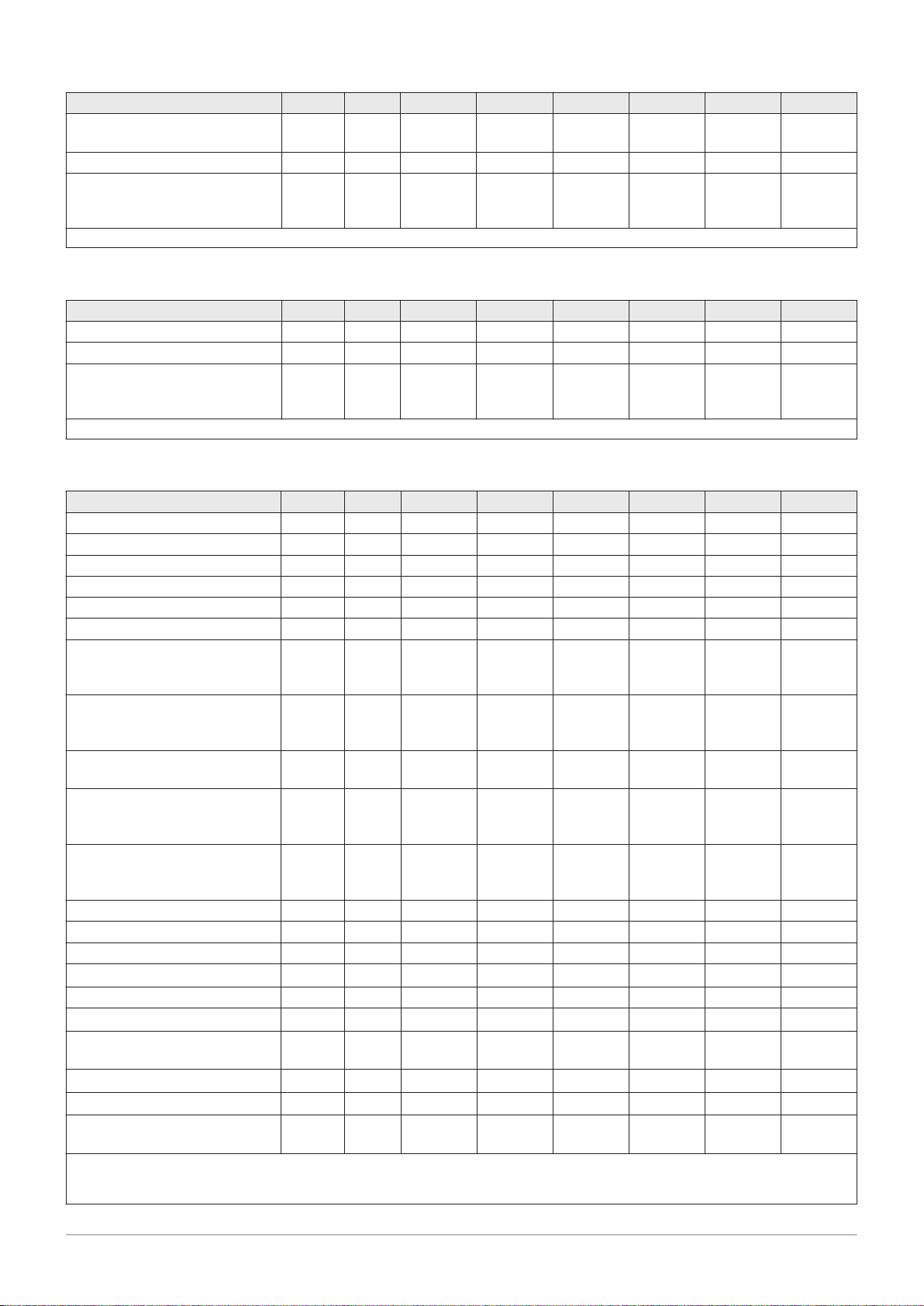
11 Technical specifications
7684359 - v.06 - 10012019 67
Quinta Ace 30 45 55 65 90 115
Power consumption - Stand-by
(1)
(Psb)
max W 6 6 7 7 7 6
Electrical protection index IP X4D X4D X4D X4D X4D X4D
Fuses (slow) Main
A 2.5 2.5 2.5 2.5 2.5 2.5
CUGH08
(1) without pump
Tab.54 Other data
Quinta Ace 30 45 55 65 90 115
Total weight including packaging kg 60.5 60.5 66.5 66.5 76.5 76.5
Minimum mounting weight
(1)
Average acoustic level at a dis
kg 50 50 56 56 65.2 65.2
dB(A) 38.3 45.1 46.7 46.7 51.6 51.1
tance of one metre from the boil
er
(1) Without front panel.
Tab.55 Technical parameters
Quinta Ace 30 45 55 65 90 115
Condensing boiler Yes Yes Yes Yes Yes Yes
Low-temperature boiler
(1)
No No No No No No
B1 boiler No No No No No No
Cogeneration space heater No No No No No No
Combination heater No No No No No No
Rated heat output
Useful heat output at nominal
Prated
P
4
kW 30 41 55 62 84 104
kW 29.8 40.8 55.3 61.5 84.2 103.9
heat output and high tempera
ture operation
Useful heat output at 30% of
(2)
P
1
kW 9.9 13.7 18.4 20.5 27.9 34.7
rated heat output and low tem
perature regime
Seasonal space heating energy
(1)
ƞ
s
% 94 94 92 94 - -
efficiency
Useful efficiency at rated heat
ƞ
4
% 89.6 89.3 88.1 89.4 88.2 87.5
output and high temperature
(2)
regime
Useful efficiency at 30% of rat
ƞ
1
% 99.5 99.6 97.9 99.5 97.4 97.3
ed heat output and low tem
perature regime
(1)
Auxiliary electricity consumption
Full load
Part load
Standby mode
elmax
elmin
P
SB
kW 0.040 0.075 0.100 0.100 0.124 0.184
kW 0.020 0.020 0.042 0.029 0.030 0.036
kW 0.006 0.006 0.007 0.007 0.007 0.006
Other items
Standby heat loss
Ignition burner power con
P
stby
P
ign
kW 0.101 0.101 0.110 0.110 0.123 0.123
kW - - - - - -
sumption
Annual energy consumption
Sound power level, indoors
Emissions of nitrogen oxides NO
Q
HE
L
WA
GJ 91 125 173 188 - -
dB 46 53 55 55 60 59
mg/kW
X
42 42 48 48 53 41
h
(1) Low temperature means 30 °C for condensing boilers, 37 °C for low temperature boilers and 50 °C (at heater inlet) for other heating
appliances.
(2) High temperature operation means 60 °C return temperature at heater inlet and 80 °C feed temperature at heater outlet.

11 Technical specifications
68 7684359 - v.06 - 10012019
See
The back cover for contact details.

AAA
A
12 Appendix
7684359 - v.06 - 10012019 69
12 Appendix
12.1 ErP information
12.1.1 Product fiche
Tab.56 Product fiche
Remeha–Quinta Ace 30 45 55 65 90 115
Seasonal space heating energy efficiency
class
Rated heat output
(Prated or Psup)
Seasonal space heating energy efficiency % 94 94 92 94 - -
Annual energy consumption GJ 91 125 173 188 - -
Sound power level LWA indoors dB 46 53 55 55 60 59
(1) For CH boilers and boilers over 70 kW, no ErP information needs to be provided.
(1)
-
kW 30 41 55 62 84 104
See
For specific precautions about assembling, installing and
maintaining: Safety, page 5
(1)
-

AD-3000743-01
%
1
‘I’
2
%+
3
%( - ‘I’ ) x 0.1 = ±
4
%(‘III’ x + ‘IV’ x ) x 0.9 x ( /100) x = +
(1)
A* = 0.95, A = 0.91,
B = 0.86, C = 0.83,
D - G = 0.81
5
%( - ‘I’ ) x ‘II’ = +
6
%0.5 x 0.5 x = -
54
<30%
G F E D C B A A
+
A
++
A
+++
%+ (50 x ‘II’) =
7
7
%
from fi che of solar device
Solar contribution AND Supplementary heat pump
Solar contribution
The energy effi ciency of the package of products provided for in this fi che may not correspond to its actual energy effi ciency once installed
in a building, as this effi ciency is infl uenced by further factors such as heat loss in the distribution system and the dimensioning of the
products in relation to building size and characteristics.
Boiler and supplementary heat pump installed with low temperature heat emitters at 35°C ?
Seasonal space heating energy effi ciency class of package
Seasonal space heating energy effi ciency of package
OR
Seasonal space heating energy effi ciency (in %)
Supplementary heat pump
Tank rating
Collector effi ciency (in
%)
Tank volume (in m³) Collector size (in m²)
Seasonal space heating energy effi ciency (in %)
Supplementary boiler
Class I = 1%, Class II = 2%, Class III = 1.5%,
Class IV = 2%, Class V = 3%, Class VI = 4%,
Class VII = 3.5%, Class VIII = 5%
Temperature control
Seasonal space heating energy effi ciency of boiler
(1) If tank rating is above A, use 0.95
select smaller value
from fi che of heat pump
from fi che of heat pump
from fi che of boiler
from fi che of temperature control
12 Appendix
70 7684359 - v.06 - 10012019
12.1.2 Package sheet
Fig.49 Package sheet for boilers indicating the space heating energy efficiency of the package

I The value of the seasonal space heating energy efficiency of the
MW-3000179-03
7684359 - v.06 - 10012019 71
preferential space heater, expressed in %.
II The factor for weighting the heat output of preferential and
supplementary heaters of a package as set out in the following
table.
III The value of the mathematical expression: 294/(11 · Prated),
whereby ‘Prated’ is related to the preferential space heater.
IV The value of the mathematical expression 115/(11 · Prated),
whereby ‘Prated’ is related to the preferential space heater.
Tab.57 Weighting of boilers
Psup / (Prated + Psup)
(1)(2)
II, package without hot water storage tank II, package with hot water storage tank
0 0 0
0.1 0.3 0.37
0.2 0.55 0.70
0.3 0.75 0.85
0.4 0.85 0.94
0.5 0.95 0.98
0.6 0.98 1.00
≥ 0.7 1.00 1.00
(1) The intermediate values are calculated by linear interpolation between the two adjacent values.
(2) Prated is related to the preferential space heater or combination heater.
12 Appendix
12.2 Disposal
Fig.50
12.3
EC declaration of conformity
12.2.1 Disposal and recycling
Caution
Only qualified professionals are permitted to remove and dispose
of the boiler, in accordance with local and national regulations.
If you need to remove the boiler, proceed as follows:
1. Switch off the boiler.
2. Cut the power supply to the boiler.
3. Close the main gas valve.
4. Close the water mains.
5. Close the gas valve on the boiler.
6. Drain the installation.
7. Remove the air/flue gas pipes.
8. Disconnect all pipes.
9. Dismantle the boiler.
The unit complies with the standard type described in the EC declaration
of conformity. It has been manufactured and commissioned in accordance
with European directives.
The original declaration of conformity is available from the manufacturer.

AD-4000062-01
x3
1
2
12 Appendix
72 7684359 - v.06 - 10012019
12.4 Optional electrical connections
12.4.1 Electronics extension box for extension PCBs
Fig.51 Open housing for extension PCBs
If there is no space in the boiler’s instrument box to install an (optional)
extension PCB, install the PCB in the electronics extension box This is
available as an accessory.
1. Unclip the housing cover.
2. Remove the cover.
3. Install the extension PCB in accordance with the instructions supplied.

12 Appendix
7684359 - v.06 - 10012019 73

12 Appendix
74 7684359 - v.06 - 10012019

© Copyright
All technical and technological information contained in these technical instructions, as well as any drawings and technical
descriptions supplied, remain our property and shall not be multiplied without our prior consent in writing. Subject to alterations.

Reme ha C ommercial UK
Innovatio ns H ouse
3 Oakland s Bu siness Centre
Oaklands Pa rk
RG41 2FD Wo ki ngham
T +44 (0)118 978 3434
F +44 (0)118 978 6977
E boilers@remeha.co.uk
7684359 - v.06 - 10012019
7684359
 Loading...