

REMEHA Quinta 85 Technical Information

Remeha Quinta 85
• High-efficiency
condensing boiler for wall
mounted installation
• Output: 14 - 90 kW
Technical information
Remeha Quinta 85

Remeha Quinta 85
2
TABLE OF CONTENT
Preface 5
1 General description of the boiler 6
2 Construction 7
2.1 Boiler layout 7
2.2 Operating principle 8
3 Technical data and dimensions 9
3.1 Dimensions 9
3.2 Technical data 10
3.3 General Specification 11
3.4 Options 12
4 Efficiency information 12
4.1 Annual efficiency 12
4.2 Heat to water efficiency 12
5 Application information 12
6 Control and safety equipment 13
6.1 The control panel 13
6.1.1 General 13
6.1.2 Layout of the control panel 13
6.1.3 Combined key functions (in operating mode only) 14
6.1.4 Display of values with more than two digits 15
6.2 Flow diagram control system 16
6.3 Operating mode (x[[) 18
6.4 Shut-off mode (bXX) 19
6.5 Setting mode user level (X[[) 20
6.5.1 Flow temperature set point (!) 21
6.5.2 Pump run on time HTG (@) 21
6.5.3 DHW temperature set point (3) 22
6.5.4 Boiler control setting (A) 22
6.6 Setting mode service level (X00) 23
6.6.1 Flow temperature set point during forced part load ($) 25
6.6.2 High limit thermostat (%) 25
6.6.3 Fan speed at full load HTG (^) 25
6.6.4 Fan speed at part load (HTG and DHW - &) 25
6.6.5 Starting point modulation (*) 25

3
6.6.6 Interface selection (() 26
6.6.7 DHW cut-in temperature (B) 26
6.6.8 Fan Speed at DHW full load (C) 26
6.6.9 Forced part load time after start (HTG only - G) 26
6.6.10 DHW control stop set point (I) 27
6.6.11 DHW control option (J) 27
6.6.12 HTG cut in temp (N) 27
6.6.13 Boiler type (P) 27
6.6.14 Maximum delay time (U) 27
6.6.15 Start and end point analog signal (Q and Y) 28
6.7 Read-out mode (X00) 28
6.8 Fan speed mode (<00) 29
6.9 Failure mode (x00) 29
7 Installation instructions 30
7.1 General 30
7.2 Location 30
7.3 Flue gas discharge and air supply 31
7.3.1 General 31
7.3.2 Classification due to discharging flue gases 32
7.3.3 Material and installation 33
7.3.4 Single boiler conventional flue 33
7.3.5 Single boiler, room sealed flue 34
7.3.6 Different pressure zones 35
7.3.7 Modular installations 36
7.4 Hydraulic installation 36
7.4.1 Condensate and AAV discharge 36
7.4.2 Water treatment 37
7.4.3 Cold feed and expansion tank height for open vented systems 38
7.4.4 Safety valve 38
7.4.5 Gas connection 39
7.4.6 System pump 39
7.4.7 Waterflow 39
7.5 DHW production 39
8 Electrical installation 42
8.1 General 42
8.2 Specifications 42
8.2.1 Electrical supply 42
8.2.2 Control box 42
8.2.3 Fuse specification 42
8.2.4 Boiler temperature control 43
8.2.5 High limit temperature protection 43
8.2.6 Low-water protection (flow and content) 43

Remeha Quinta 85
4
8.3 External connections 43
8.4 Boiler control 44
8.4.1 Modulating (two wire control) 44
8.4.2 Analog control (0 -10 Volt dc) 46
8.4.3 On / off control (1 x no volt switched pair) 47
8.4.4 High / low control (2 x no volt switched pairs) 48
8.5 DHW control (Broag priority) 48
8.5.1 Temperature control 48
8.5.2 Primary flow control 48
8.6 System pump 48
8.7 Frost protection 48
8.8 Remote alarm and boiler run indication 48
8.9 Safety interlock 49
9 Commissioning 50
9.1 Shut-down 53
9.1.1 Temporary shut-down with frost protection 53
9.1.2 Permanent shut-down without frost protection 53
10 Fault-finding 54
10.1 General (all installations) 54
10.2 Fault codes 55
11 Inspaction and servicing instructions 59
11.1 General 59
11.2 Annual Inspection 59
11.3 Maintenance 60
11.4 Cleaning the fan 61
11.5 Cleaning the venturi 61
11.6 Cleaning the heat exchanger 61
11.7 Cleaning the burner assembly 61
11.8 Cleaning the siphon 61
11.9 Cleaning/replacing the ignition/ionisation electrode 62
11.10 Cleaning to inspection glass 62
11.11 Part list Quinta 85 boiler 63
5
PREFACE
These technical instructions contain useful and important information for the correct
operation and maintenance of the Remeha HTG boiler, model Quinta 85.
Read these instructions carefully before putting the boiler into operation, familiarise
yourself with it’s control functions and operation, strictly observing the instructions
given. Failure to do so may invalidate warranty or prevent the boiler from operating.
The installation and commissioning of the boiler must be carried out by a competent
Engineer, with the relevant certification ie: CORGI, ACOPS, IEE regs. etc.
On completion a copy of the commissioning sheet should be returned to Broag Ltd for
record purposes.
If you have any questions, or if you need more information about specific subjects
relating to this boiler, or it’s installation please do not hesitate to contact us.
The data published in these technical instructions is based on the latest information (at
date of publication) and may be subject to revisions.
We reserve the right to continuous development in both design and manufacture,
therefore any changes to the technology employed may not be retrospective nor may
we be obliged to adjust earlier supplies accordingly.

Remeha Quinta 85
6
1 GENERAL DESCRIPTION OF THE BOILER
The Remeha Quinta 85 is a wall hung condensing boiler which may be also installed
free standing on a suitable frame (option). The one piece cast aluminium heat
exchanger and other major components are contained within a sealed air box. This
forms the main boiler casing with a removable front section for maintenance purposes.
All electrical and electronic controls are contained within the instrument panel mounted
behind the drop down lower front panel.
The combined flue gas outlet and combustion air inlet are mounted on the top of the
boiler with the flow, return, gas and condensate connections located at the bottom.
The boiler is suitable for room sealed or open flue applications and has been designed
for central heating and indirect hot water production at working pressures not
exceeding 4 bar. It must be installed on a fully pumped system and is suitable for use
on both sealed and open vented installations (minimum operating pressure of 0.8 bar).
The pre-mix, down firing gas burner (NG or PROPANE) with its gas/air ratio control
system ensures clean, trouble free operation with higher than average efficiencies of
109% (NCV) in the condensing mode combined with ultra low NOx and minimum CO
emissions. The standard control package allows actual and set values to be read and
adjusted on the built in digital display which also provides normal operating and fault
code indication.
An intelligent, advanced boiler control (‘abc’) continuously monitors the boiler
conditions, varying the heat output to suit the system load. The control is able to react
to external “negative” influences in the rest of the system (flow rates, air / gas supply
problems) maintaining boiler output for as long as possible without resorting to a lock
out condition. At worst the boiler will reduce it’s output and/or shut down (shut-off
mode) awaiting the “negative” conditions to return to normal before re-starting.
The ‘abc’ control cannot override the standard flame safety controls.
The boiler meets the requirements of the EC regulations according to the following
directives:
- 90/396EEC Gas appliances directive
- 92/42/EEC Efficiency directive
- 73/23/EEC Electrical low voltage directive
- 89/336/EEC Directive on electromagnetic compatibility E.M.C.
- 97/23/EEC Pressure equipment directive PED (art. 3, part 3)
Remeha Quinta 85 - PIN: 0063BL3253

7
2 CONSTRUCTION
2.1 Boiler layout
Fig. 01 Boiler layout Remeha Quinta 85
pdf
1. Automatic air vent
2. Air supply fan
3. Gas combi-block (with governor)
4. Gas injector/venturi
5. Cast aluminium heat exchanger
6. Temperature sensor-return
7. Air inlet tube
8. Pressure gauge
9. Control panel
10. Facility for incorporating a rematic
®
weather compensated boiler control
11. Heat exchanger inspection cover
12. Sight glass
13. Combined ignition/ionisation probe
14. Temperature sensor-flow
15. Pre-mix burner

Remeha Quinta 85
8
2.2 Operating principle
Combustion air is drawn into the closed air box by a variable speed fan, through the
air inlet connection from the plant room (open flued) or from outside via the concentric
flue system (room sealed). On the inlet side of the fan is a specially designed venturi
which is connected to the outlet side of the gas combi block.
Depending on the demand (under the dictates of flow/return sensor and other external/
internal control inputs) the electronic control unit directly monitors the volume of gas
and air being delivered to the premix burner. This mixture is initially ignited by the
combined ignition/ionisation probe which then monitors the state of the flame. Should
the flame not ignite or is unstable within the pre-set safety time cycle the controls will
shut the boiler down (after 5 attempts) requiring manual intervention to reset the boiler.
The digital display will also indicate a flashing fault code confirming the reason for the
failure.
The products of combustion in the form of hot flue gases are forced through the heat
exchanger transfering their heat to the system water (the flue gas temperature is
reduced to approximately 5°C above the temperature of the system return water) then
discharged via the condensate collector, vertically through the 100/150 mm combined
flue/air connection to atmosphere.
Because of the low flue gas exit temperature there will be a vapour cloud formed
at the flue gas terminal - this is not smoke, simply water vapour formed during the
combustion process.
If the controls allow the flow and therefore return temperature to fall below dew point
(55°C) this water vapour will begin to condense out in the boiler, transfering it’s latent
heat into the system water, increasing the output of the boiler without increasing the
gas consumption.
Condensation formed within the boiler and flue system is discharged from the boiler to
an external drain via the drain pan / siphon supplied.
9
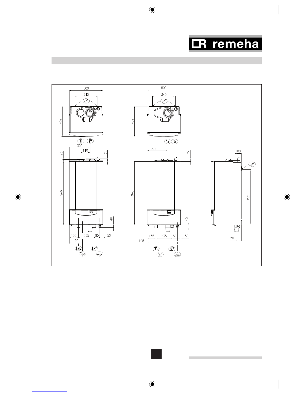
3 TECHNICAL DATA AND DIMENSIONS
3.1 Dimensions
Fig. 02 Dimensions Remeha Quinta 85
00.W4H.79.00048 + 05.W4H.79.00024
Ê Return connection 1¼” BSP (m)
É Flow connection 1¼” BSP (m)
Ï Gas connection ¾” BSP (m)
Ò Condensate connection 25 mm Ø o/d (plastic)
Ñ Flue gas connection 100 mm Ø i/d
Ð Combustion air supply connection 150 Ø i/d or
** Combustion air supply connection 100 Ø i/d, see Par. 7.3.1
ã Holes for mounting bracket
**
Remeha Quinta 85
10
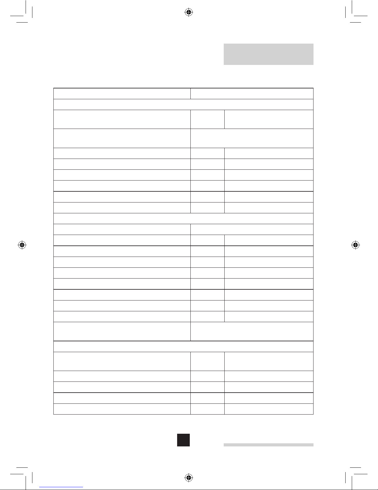
3.2 Technical data
Boiler type Quinta 85
General
Colour side and front casing
Colour instrument panel flap
BS RAL
9016
7036
Boiler control options (External input)
(Two wire control)
On/off, High/low, Analog 0 -10V
Communicating Modulation
Nominal output (80/60ºC) kW 14.1 - 84.2
Nominal output (50/30ºC) kW 15.8 - 89.5
Nominal input (GCV / H
s
) kW 16.2 - 95.3
Nominal input (NCV / Hi) kW 14.6 - 86.0
Weight dry kg 72
Noise level at 1 m from boiler dB(A) < 52
Gas- and flue details
Category II
2H3P
Min/Max Inlet pressure natural gas mbar 17 - 30
Min/Max Inlet pressure propane mbar 37 - 50
Gas consumption (natural gas) m
3
/h 1.5 - 9.1
Gas consumption (propane) m
3
/h 0.6 - 3.5
NO
x
-emission *) mg/kWh < 47
NO
x
-emission (O2 = 0%, dry) *) ppm < 27
Residual fan duty Pa 160
Mass flue rate kg/h 23 - 138
Classification due to discharging flue
gases
B23, C13, C33, C43, C53,
C63, C83
Water side
Maximum flow temperature
ºC 100 (110)
Operating flow temperature ºC 20 - 90
Operating pressure min. (open vented) bar 0.3
Operating pressure min. (pressurised) bar 0.8
Operating pressure max. bar 4.0
11
Water contents ltr 7.5
Water resistance at 11 °C dt
mbar 460
Water resistance at 20 °C dt
mbar 140
Nominal flow at 11 °C dt
l/s 1.74
Nominal flow at 20 °C dt
l/s 0.96
Electrical
Main supply V/Hz 230 / 50
Electric rating without pump (max) W 30 - 160
Insulation class IP 20
Table 01 Technical data Remeha Quinta 85
*) DIN 4702, part 8
3.3 General Specification
(to be read with above table)
- One piece cast aluminium heat exchanger.
- 1¼” BSP (m) flow and return connections.
- ¾” BSP (m) gas connection.
- Maximum operating pressure of 4.0 bar.
- Maximum operating temperature of 95°C.
- Low NO
x
(max 27 ppm, O2= 0%, dry) DIN 4702, part 8.
- Pre-mix, fully modulating (18 -100%) gas burner with gas/air ratio control for
maximum efficiency.
- Intelligent advanced boiler control ‘abc’ c/w a comprehensive operating, service
and fault diagnostic facility.
- Available for conventional flue or room sealed operation.
- Capable of remote BMS (0 -10V, on/off and High/low control options).
- Supplied fully factory assembled.
- Powder coated enamel steel casing.
- Suitable for use with a Natural gas as standard or propane (with boiler parameters
change and included restrictor, also see the included “Assembly instructions
Propane set” )
- Supplied as standard with safety interlock facility, temperature indication, control
and high limit sensors, common alarm and boiler run indication.
- Efficiency of 98% at 80/60°C (H
i
).
- Max efficiency of 108% (H
i
) in fully condensing mode.
- Manufactured to ISO 9001.
- CE approved.

Remeha Quinta 85
12
3.4 Options
- Floor frame.
- Two pipe flue/air inlet adapter plate (excentric room sealed).
- DHW-sensor.
- Weather compensating controllers.
- Heat exchanger cleaning tool.
- EMC filter for boiler sensor or boiler thermostat cables
(when sensor wires exceed 3 m. length).
4 EFFICIENCY INFORMATION
4.1 Annual efficiency
108% at H
i
at an input of 30% and a return temperature of 30°C.
4.2 Heat to water efficiency
a. Up to 98% at Hi at an average water temperature of 70°C (80/60°C).
b. Up to 108% at Hi at an average water temperature of 40°C (50/30°C).
NOTE: NCV = H
i
, GCV = H
s
5 APPLICATION INFORMATION
The Quinta 85 can be used on all new and re-furbishment projects in both single and
multiple configurations. Conventional and room sealed flue system capability means
that the boiler can be sited almost anywhere within a building.
The Remeha range of weather compensators (options) are able to communicate
directly with the boiler controls (two wire) to make full use of it’s fully modulating
feature, ensuring that the boiler closely matches the system demand at all times.
External control systems (BMS) can be interfaced with the boiler to provide on/off high/low or modulating (0 -10 V) control options.
13
6 CONTROL AND SAFETY EQUIPMENT
6.1 The control panel
6.1.1 General
The boiler is supplied with a standard set of defaults pre-programmed for normal
operation but can be tailored by the Engineer to suit most site conditions. These
values are set and read using the built in control panel or with a notebook computer/
PDA (with an interface and software available from Broag).
For security the control has three levels of access:
- User level - free access
- Service level - access with service code by qualified personnel
- Factory level - access by PC/PDA with factory code (Remeha only)
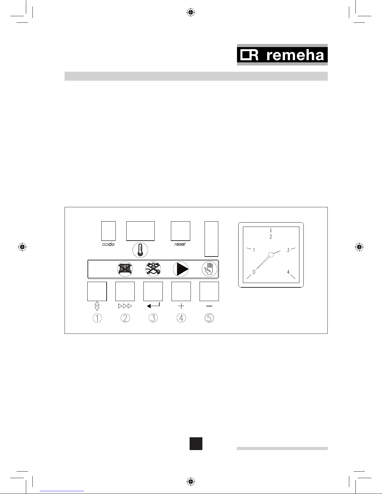
6.1.2 Layout of the control panel
Fig. 03 Control panel
00.W4H.79.00044
Remeha Quinta 85
14
a. ‘code’-display
Indicates on user level:
operating mode: only one digit 1
setting mode: digit with dot !
read-out mode: digit with flashing dot !
shut-off mode: letter b
forced full load: letter h
forced part load: letter l
Additional indication on
service level:
speed mode: alternate half digit <
failure mode: flashing digit 1
b. t-display
Indicates:
Temperatures, settings, fault codes (flashing digits),
shut-off codes (flashing dots)
c. reset-key: to reset after a lockout condition
d. ‘m’ -key:
Program function: key to select the required mode
e. ‘s’-key:
Program function: key to select the required program
within the selected mode
e. ‘s’-key + r-
symbol:
Switch function: burner switch HTG (manual override)
f. ‘e’-key:
Program function: key to save the settings
f. e-key + k-symbol:
Switch function: burner switch DHW (manual override)
g. [+]-key: Program function: to select a higher setting
g. [+]-key + q-symbol:
Switch function: pump manual override
h. [-]-key: Program function: to select a lower setting
h. [-]- key+ h-symbol:
Switch function: manual override (hand/auto)
Table 02 Control panel functions
6.1.3 Combined key functions (in operating mode only)
When the boiler is in the operating mode, keys with the illuminated symbols above
have a double function (Program and Switch).
To use them for a Program function press the key once - and for a Switch function
(either on or off) press the key and hold for 2 secs.
The status of the switch function will be confirmed by the illuminated symbol as
follows:

15
‘s‘-key and r-symbol:
- (symbol) not illuminated: HTG under normal control
- red (symbol) on: HTG off (manual override)
‘e’-key and k-symbol:
- (symbol) not illuminated: DHW under normal control
- red (symbol) on: DHW off (manual override)
[+]-key and q-symbol:
- green (symbol) on: continuous pump operation
- (symbol) not illuminated: pump under boiler control
[-]-key and h-symbol:
- green (symbol) on: HTG on (manual override)
- (symbol) not illuminated: HTG under normal control
NOTE: In the Switch function, (in order to protect the boiler and the installation) the
flow temperature cannot exceed it’s pre-set maximum. It is also not possible to change
any parameters.
Forced mode ‘high’ (h[[)
By pressing the ‘m’ and [+]-key simultaneously in operating mode, the boiler will burn
at maximum power. The letter h will now appear on the display.
By pressing the [+] and [-]-keys simultaneously, the boiler will return to operating
mode. Following a manual override the boiler will return to normal (auto control) if no
keys are used within a 15 minute period
Forced mode ‘low’ (l[[)
By pressing the ‘m’ and [-]-key simultaneously in operating mode, the boiler will burn at
minimum power. The letter l will now appear on the display. By pressing the [+]and [-]-
keys simultaneously, the boiler will return to operating mode. Following a manual override
the boiler will return to normal (auto control) if no keys are used within a 15 minute period.
6.1.4 Display of values with more than two digits
The display has only two digits available therefore values over this are displayed as
follows :
- negative values will be indicated by a dot behind the last digit e.g. 1) = -10
- values from 00 to 99 will be indicated without any punctuation marks
- values from 100 to 199 will be indicated by a dot between both digits
e.g. )0 = 100, !0 = 110, (9 = 199.
- values from 200 to 299 will be indicated by a dot behind every digit
e.g. )) = for 200, !) = 210, (( = 299.
Remeha Quinta 85
16
6.2 Flow diagram control system
press the ‘m’ -key press the ‘s’-key
‘code’-display
tdisplay
Operating mode,
see Par. 6.3
only digit or letter
0 - 9,h,l,b
Flow temperature or shut-off code
Setting mode,
user level,
see Par. 6.5
digit or letter with
dot
!
Flow temperature set point
@
Pump run on time HTG
#
DHW temperature set point
A
Boiler control setting
u
n/a
Setting mode,
service level,
see Par. 6.6
service engineer level only:
$
Flow temperature set point during forced part
load
%
High limit temperature set point
^
Fan speed at full load (HTG)
&
Fan speed at part load (HTG and DHW)
*
Modulation start point dt (F/R)
(
Interface selection (control option)
B
DHW cut-in dt
C
Fan speed at full load (DHW)
D
intern
17
E
n/a
F
n/a
G
Forced part load time after start (HTG)
H
Fan speed at start
I
DHW control stop or boiler modulation set
point (based on parameter #)
J
DHW control mode
L
n/a
N
HTG cut in dt (based on return)
O
n/a
P
Boiler type
T
intern
U
Maximum delay time
Q
Start point for 0 Volt analog signal
Y
End point for 10 Volt analog signal
_
intern
Read-out mode,
see Par. 6.7
digit or letter with
flashing dot
!
Actual flow temperature
@
Actual return temperature
#
Actual DHW temperature (with sensor)
$
Actual outdoor temperature (with
Chronotherm sensor)
%
n/a
^
Flow temperature (set point)
&
Actual heat demand status
*
Calculated HTG cut-in temperature
(
Actual flow temperature rise
A
n/a
Remeha Quinta 85
18
service engineer level only:
Speed mode,
see Par. 6.8
alternate half
digit <
Fan speed
Failure mode,
see Par. 6.9
flashing digit
1
Failure code
2
Operating code during failure
3
Flow temperature during failure
4
Return temperature during failure
5
DHW temperature during failure
6
n/a
Table 03 Flow diagram control system
6.3 Operating mode (x[[)
During operation the code-display shows the status (position in cycle) of the boiler,
whilst the t-display indicates the actual flow temperature.
The digits or letters in the code-display have the following meaning:
Code Description
0
Standby: there is no heat demand from control system.
1
Pre-purge: before start-up, the boiler is purged for 4.2 seconds.
Post-purge: when the heat demand has been met, the fan continues to
operate for another 10 seconds.
2
Ignition: ignition is activated for 2.4 seconds while the gas valve is opened.
3
HTG mode; the boiler operates in the HTG mode.
4
DHW mode: the three way valve or DHW pump activated (Broag priority only)
5
Internal check
6
Normal control stop during HTG (flow temperature > set point + 5 °C)
7
HTG pump run on
8
DHW pump run on or for three way valve option, HTG pump run on with
valve open to DHW (max. 5 minutes)
9
Normal control stop during DHW (flow temperature > set point DHW + DHW
control stop set point + 5°C)

19
b
Shut-off mode
h
Forced full load.
l
Forced part load.
Table 04 Operating codes
6.4 Shut-off mode (bXX)
During shut-off mode condition the code-display will show a b, whilst the t-display
indicates the cause with two flashing dots.
Table below details cause of shut-off mode.
Code Description
B@%
Maximum acceptable flow temperature rise exceeded. The boiler will shut
off for ten minutes, then restart. Should the flow temperature conditions
remain the same after 5 attempts, this code will be recorded as a shutdown failure. Boiler will not lockout.
b@^
Contacts of the external interlock have opened during heat demand.
The boiler will shut off for 120 seconds. Should the contacts close again
during heat demand, the boiler will wait the remaining time from the 120
seconds before attempting a restart.
B@*
Internal check on fan speed. After 5 attempts, the boiler will lockout. This
code will be recorded.
B@(
Internal check on fan speed. After 5 attempts, the boiler will lockout. This
code will be recorded.
B#)
Maximum temperature difference between flow and return exceeded. The
boiler will shut off for 150 seconds, then restart. Should the temperature
difference conditions remain the same after 10 attempts, this code will be
recorded as a shut-down failure. Boiler will not lockout.
B$#
One or several adjusted parameters out of range including some
factory defaults which should not have been changed. Check and reset
parameters:
- press the ‘reset’-key imidiately followed by pressing the ‘m’-key for
about 12 sec.,
- ‘code’- display shows P ,
- use [+] and [-]-keys to enter correct boiler parameter ( P=80),
- press ‘e’-key to confirm settings,
- check parameter settings and change were needed or disired.
Table 05 Shut-off codes
Remeha Quinta 85
20
NOTE: Shut-off mode is a normal boiler operating function and does not represent a
boiler failure.
However, this may indicate a system problem, an internal boiler check or an incorrect
parameter setting.
6.5 Setting mode user level (X[[)
Code Description Setting range Preset
!
Flow temperature set
point
20–90 ºC 80
@
Pump run on time
HTG
00 = pump run on 10
seconds
03
01–15= pump run on in minutes
#
DHW temperature set
point
20–75 °C (only with sensor) 55
A
Boiler control setting Control mode (modulating-on/off etc.)
11
u
Base point internal
compensation slope
n/a
20
Table 06 Setting mode user level
Note: Changing code @ and code A should only be on design engineers advice.
21
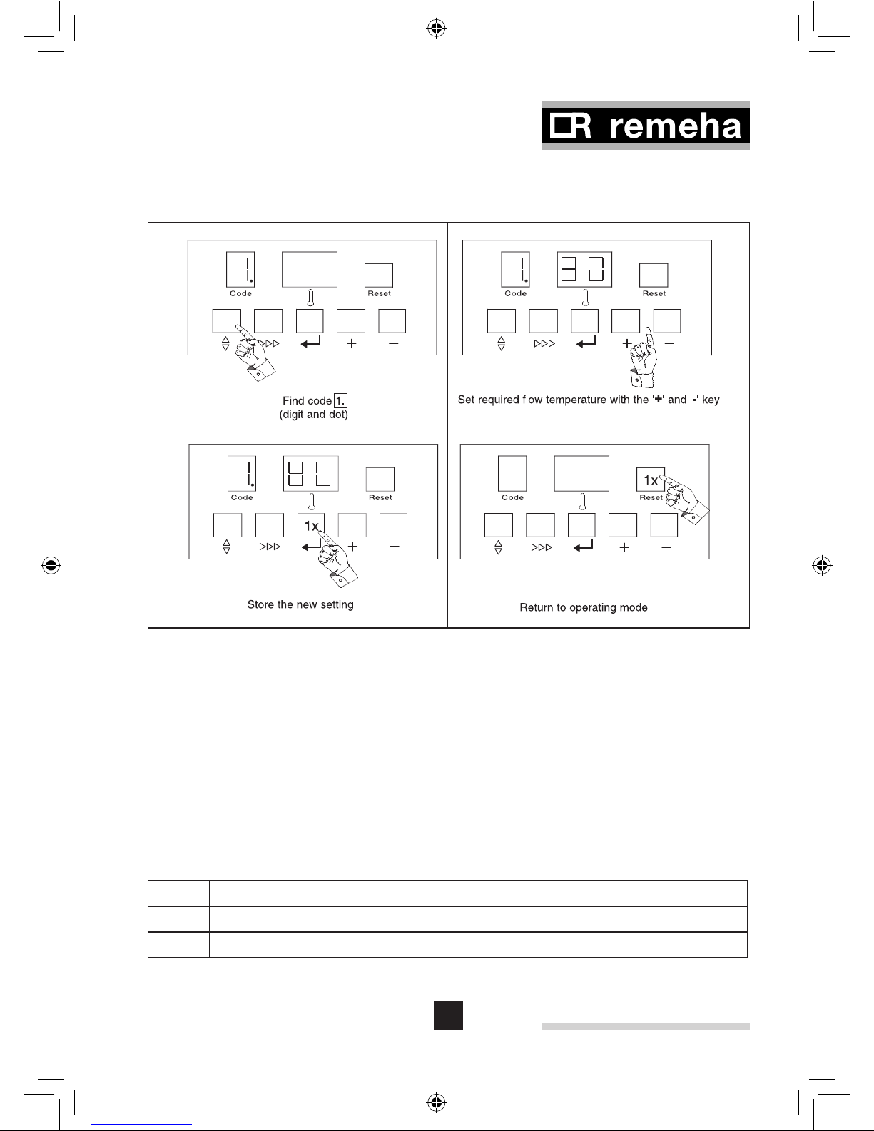
6.5.1 Flow temperature set point (!)
The required flow temperature is adjustable from 20 to 90°C (factory default 80°C).
Fig. 04 Typical setting change procedure
pdf
6.5.2 Pump run on time HTG (@)
Pump run on time can be adjusted (Please refer to installation contractor)
- Press the ‘m’ -key until the digit ! (with dot) appears in the ‘code’-display.
- Press the ‘s’-key until the digit @ (with dot) appears in the ‘code’-display.
- Set the required value, using the [+] and [-]-keys.
- Press the ‘e’-key to store the new value (value will flash twice).
- Press the ‘reset’-key to return to operating mode.
NOTE: For continuous pump operation use manual override, see Par. 6.1.3.
Code
t
Description
@00
Pump runs on for 10 seconds
@Xx Pump runs on for 1 to 15 minutes (xx = 01 to 15)
Table 07 Pump run on time HTG
 Loading...