

Regency Trinity Installation Manual
TrinityMk II
WOODBURNING STOVE
SAFETY NOTICE
Please read this entire manual before you install and use your new room heater. Failure to follow instructions
may result in property damage, bodily injury or even death.
If this stove is not properly installed, a house fire may result. For your safety, follow the installation directions.
Contact local building or fire officials about restrictions and installation inspection requirements in your area.
This appliance is hot while in operation and retains its heat for a long period of time after use. Children, aged
or infirm persons should be supervised at all times and should not be allowed to touch the hot working surfaces
while in use or until the appliance has thoroughly cooled.
This stove must be connected to a UL/U.L.C. listed High Temperature residential chimney, Factory Built,
Residential Type and Building Heating Appliance, UL 103 or a code approved masonry chimney flue liner
constructed in accordance with NFPA 211 Chimney Vents and Solid Fuel Burning Appliances
Manufactured by Waterford Stanley (Marketing) Limited, Bilberry, Waterford, Ireland.
INSTALLATION & OPERATING INSTRUCTIONS

TABLE OF CONTENTS
PAGE NO.
1. General . . . . . . . . . . . . . . . . . . . . . . . . . . . . . . . . . . . . . . . . . . . . . . . . . . . . . . . . . . . . . 2
2. Pre-Installation Assembly . . . . . . . . . . . . . . . . . . . . . . . . . . . . . . . . . . . . . . . . . . . . . . . . 2
3. Top Flue Exit . . . . . . . . . . . . . . . . . . . . . . . . . . . . . . . . . . . . . . . . . . . . . . . . . . . . . . . . . . 3
4. Rear Flue Exit . . . . . . . . . . . . . . . . . . . . . . . . . . . . . . . . . . . . . . . . . . . . . . . . . . . . . . . . . 3
5. Blower. . . . . . . . . . . . . . . . . . . . . . . . . . . . . . . . . . . . . . . . . . . . . . . . . . . . . . . . . . . . . . . 3
6. Blower Operation Instructions . . . . . . . . . . . . . . . . . . . . . . . . . . . . . . . . . . . . . . . . . . . . 3
7. Floor Protection. . . . . . . . . . . . . . . . . . . . . . . . . . . . . . . . . . . . . . . . . . . . . . . . . . . . . . . . 4
8. Location. . . . . . . . . . . . . . . . . . . . . . . . . . . . . . . . . . . . . . . . . . . . . . . . . . . . . . . . . . . . . . 4
9. Outside Air Connection. . . . . . . . . . . . . . . . . . . . . . . . . . . . . . . . . . . . . . . . . . . . . . . . . . 4
10. Mobile Home Installation. . . . . . . . . . . . . . . . . . . . . . . . . . . . . . . . . . . . . . . . . . . . . . . . . 5
11. Minimum Clearances to Combustible Materials . . . . . . . . . . . . . . . . . . . . . . . . . . . . . . . 5
12. Reduced Clearances. . . . . . . . . . . . . . . . . . . . . . . . . . . . . . . . . . . . . . . . . . . . . . . . . . . . 6
13. Double Wall Connections . . . . . . . . . . . . . . . . . . . . . . . . . . . . . . . . . . . . . . . . . . . . . . . . 6
14. Wall Protectors . . . . . . . . . . . . . . . . . . . . . . . . . . . . . . . . . . . . . . . . . . . . . . . . . . . . . . . . 6
15. Chimney . . . . . . . . . . . . . . . . . . . . . . . . . . . . . . . . . . . . . . . . . . . . . . . . . . . . . . . . . . . . . 7
16. Chimney Types: USA Only . . . . . . . . . . . . . . . . . . . . . . . . . . . . . . . . . . . . . . . . . . . . . . 7
17. Chimney Types: Canada Only. . . . . . . . . . . . . . . . . . . . . . . . . . . . . . . . . . . . . . . . . . . . 7
18. Chimney Connectors. . . . . . . . . . . . . . . . . . . . . . . . . . . . . . . . . . . . . . . . . . . . . . . . . . . . 7
19. Connecting to Masonry Chimney . . . . . . . . . . . . . . . . . . . . . . . . . . . . . . . . . . . . . . . . . . 7
20. Thimbles . . . . . . . . . . . . . . . . . . . . . . . . . . . . . . . . . . . . . . . . . . . . . . . . . . . . . . . . . . . . . 8
21. Chimney Connector Systems, Thimbles & Clearances from Combustible Walls. . . . . . 8
22. Masonry Fireplace. . . . . . . . . . . . . . . . . . . . . . . . . . . . . . . . . . . . . . . . . . . . . . . . . . . . . . 9
23. Ventilation & Combustion Air Requirements . . . . . . . . . . . . . . . . . . . . . . . . . . . . . . . . . 10
24. Spillage Test. . . . . . . . . . . . . . . . . . . . . . . . . . . . . . . . . . . . . . . . . . . . . . . . . . . . . . . . . . 10
25. Lighting. . . . . . . . . . . . . . . . . . . . . . . . . . . . . . . . . . . . . . . . . . . . . . . . . . . . . . . . . . . . . . 10
26. Primary Air Settings . . . . . . . . . . . . . . . . . . . . . . . . . . . . . . . . . . . . . . . . . . . . . . . . . . . . 10
27. Low or Overnight Burn . . . . . . . . . . . . . . . . . . . . . . . . . . . . . . . . . . . . . . . . . . . . . . . . . . 11
28. Maintenance. . . . . . . . . . . . . . . . . . . . . . . . . . . . . . . . . . . . . . . . . . . . . . . . . . . . . . . . . . 11
29. De-Ashing (When Fire has Burned Out) . . . . . . . . . . . . . . . . . . . . . . . . . . . . . . . . . . . . 11
30. Disposal of Ashes . . . . . . . . . . . . . . . . . . . . . . . . . . . . . . . . . . . . . . . . . . . . . . . . . . . . . 11
31. Creosote (Formation & Need for Removal) . . . . . . . . . . . . . . . . . . . . . . . . . . . . . . . . . . 11
32. Glass Replacement . . . . . . . . . . . . . . . . . . . . . . . . . . . . . . . . . . . . . . . . . . . . . . . . . . . . 11
33. Glass Cleaning. . . . . . . . . . . . . . . . . . . . . . . . . . . . . . . . . . . . . . . . . . . . . . . . . . . . . . . . 12
34. Vitreous Enamel Cleaning . . . . . . . . . . . . . . . . . . . . . . . . . . . . . . . . . . . . . . . . . . . . . . . 12
35. Fire Safety . . . . . . . . . . . . . . . . . . . . . . . . . . . . . . . . . . . . . . . . . . . . . . . . . . . . . . . . . . . 12
36. In the Event of a Chimney Fire . . . . . . . . . . . . . . . . . . . . . . . . . . . . . . . . . . . . . . . . . . . 12
37. Exploded View . . . . . . . . . . . . . . . . . . . . . . . . . . . . . . . . . . . . . . . . . . . . . . . . . . . . . . . . 13
1

WATERFORD TRINITY MKII WOODBURNING STOVE INSTALLATION AND OPERATING
INSTRUCTIONS
GENERAL
When installing, operating and maintaining your
Waterford Trinity MK II Stove respect basic
standards of fire safety. Read these instructions
carefully before commencing the installation. Failure
to do so may result in damage to persons and
property. Consult your local Municipal office, Fire
Department and your insurance representative to
determine what regulations are in force. Save these
instructions for further reference.
The complete installation must be done in
accordance with current Standards and Local
Codes. It should be noted that the requirements
and these publications may be superseded during
the life of this manual.
PRE-INSTALLATION ASSEMBL Y
(a) After removing the stove from its packing, open
the ashpit door (item 13 in exploded view) and
remove the contents
(b) Open the firedoor (item 8) and remove the
contents of the firebox, leaving the bricks in
place.
Fig.2
(f) Fit the front ashlip (item 12) using two of the
ashlip brackets (item 35) and screw together
using four 1/4” (6mm) x 1/2” (12mm) hex head
bolts provided. Stand the stove upright taking
care not to strain the back leg bolts.
Fig.3
(c) Remove the ashlip (item 12) from the rear of the
stove if you have not already done so. Remove
the loose fitting hob (item 3) and place on a nonabrasive surface.
Fig.1
(d) Place the plastic packing on the ground at the left
hand side of the stove.
NOTE: As the stove is very heavy take care when
laying the stove on its side on top of the packing.
(g) Fit the wooden handle (item 28) to the fuelling
door (item 8)
Fig.4
(e) Remove the wooden pallet by taking out the 4
retaining screws from the base of the legs (item
2). Discard brackets & woodscrews, replace
levelling screws.
h) If the side fuelling door (item 21) is to be used, fit
the side ash lip (item 24) using two ashlip
brackets (item 35) and screw together using four
2
1/4” (6mm) x 1/2” (12mm) hex head bolts provided.
Take out the chrome locking bolt and fit door latch
(item 73), the door latch spigot (item 40), and the
wooden handle (item 28) provided.
Fig.5
Fig. 7
BLOWER
This stove can be connected to either a top or rear
exit by simply reversing the orientation of the flue
spigot (item 5) on the flue spigot flange.
For either the top or the rear exit option place the
ceramic gasket onto the flue spigot flange – located
at the top of the back plate (item 31).
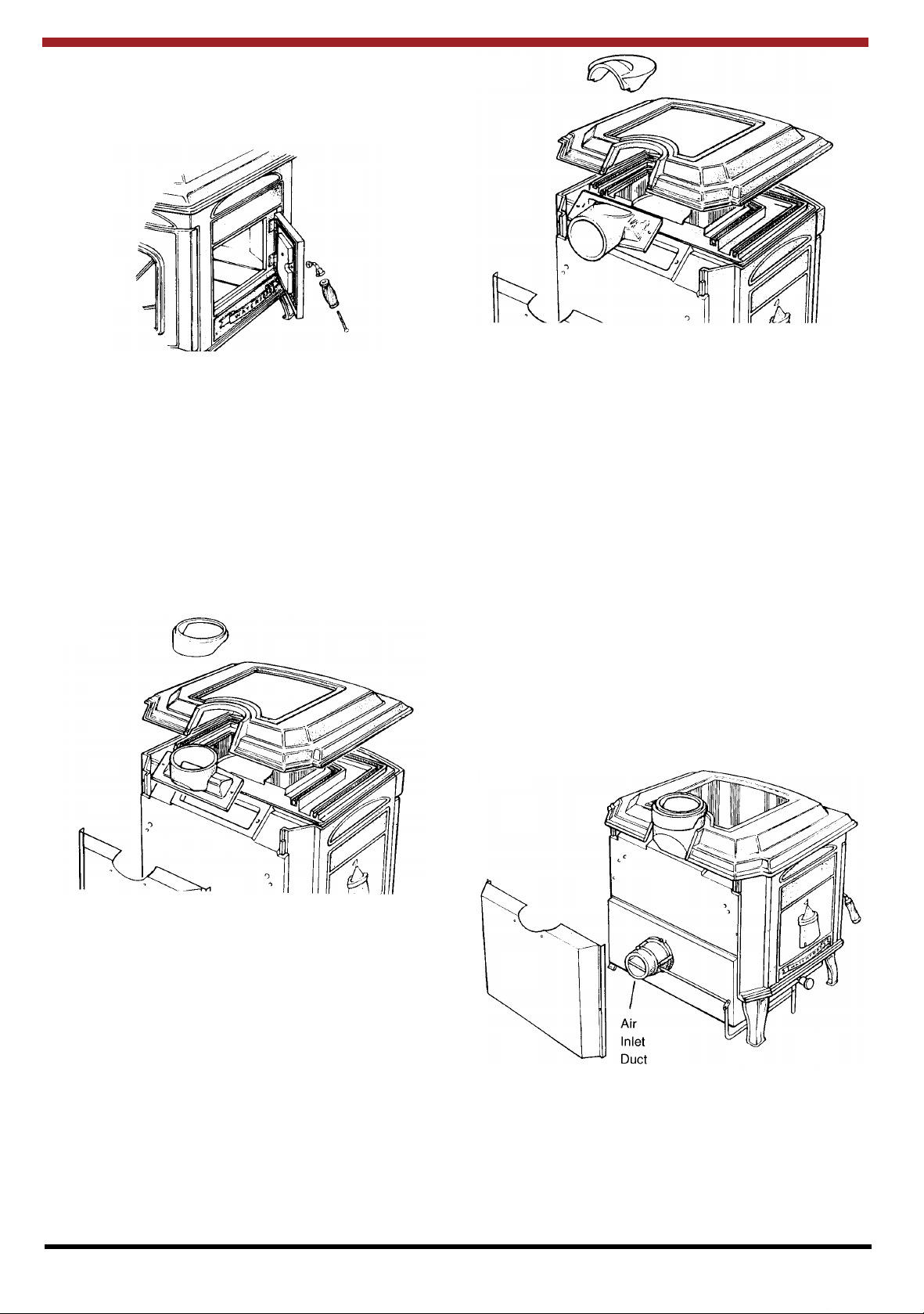
TOP FLUE EXIT
Screw the top outlet hob filler piece (item 6) onto the
hob (item 3), screw top outer blanking plate (item
29) onto the heat shield (item 30) using the two 1/4”
(6mm) x 3/4” (19mm) C/S screws provided.
Fig. 6
Caution: Moving parts may cause injury. Do not
operate unit with blower housing removed.
Danger: Risk of electric shock. Disconnect power
before servicing unit.
Hot parts: Do not operate unit with blower housing
removed.
The Listed Waterford Trinity Optional Blower comes
assembled, wired, and ready for use.
To fit the Listed Waterford Trinity MK II Optional
Blower take off rear heat shield (item 30) and fit
listed blower assembly (item 75) as per illustrations
below.
This unit must be connected to a grounded,
Standard 110 volt, 60 Hz electrical outlet, Never
route the power cord under or in front of the unit.
Do not, under any circumstances, cut or remove the
grounding prong from the power cord.
Do not use an adaptor plug.
Fig. 8
REAR FLUE EXIT
Screw the rear outlet hob filler piece (item 57) to the
hob (item 3) using the two screws provided.
Screw the rear outlet heat shield blanking plate (item
58) to the heat shield (item 30) using the two 1/4”
(6mm) x 3/4” (19mm) C/S screws provided.
BLOWER OPERATION INSTRUCTIONS
1. Press switch to ON position (see fig. 9).
2. Fan will power up when stove temperature
reaches snap switch operating temperature.
3. Fan operation will cease each time stove
temperature drops below snap switch operating
temperature.
3
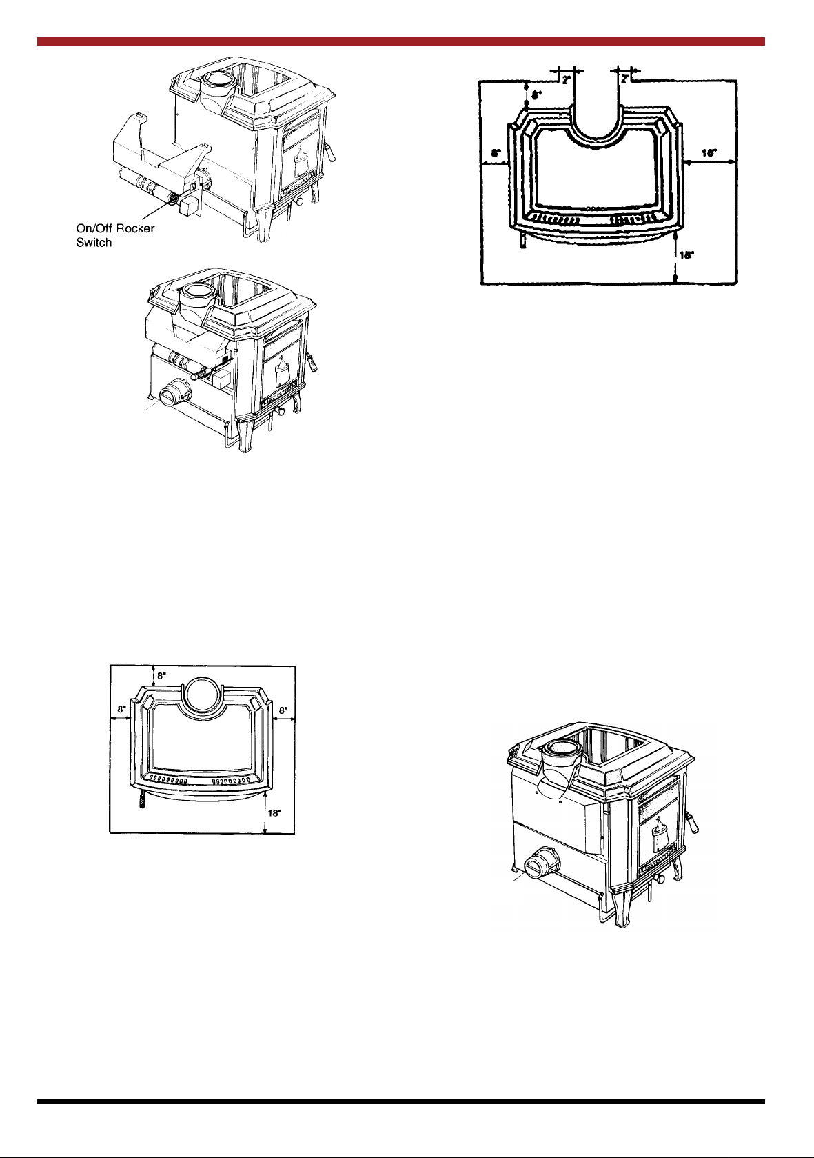
Fig. 9
Fig. 12
200mm
50mm
50mm
Fig. 10
Air inlet
duct
FLOOR PROTECTION
When installing this heater on a combustible floor, a
floor protector, consisting of a layer of noncombustible material at least 3/8” (9mm) thick or 1/4”
(6mm) thick covered with 1/8” (3mm) sheet metal is
required to cover the area under the heater and to
extend to at least 18” (450mm) at the front and 8”
(200mm) to the sides. This will provide protection
from sparks and embers which may fall out from the
door when stoking or fuelling.
200mm
450mm
450mm
LOCATION
There are several conditions to be considered when
selecting a location for your Waterford Trinity MK II
Wood Stove.
(a) Distance from a safe chimney.
(b) Position in the area to be heated - central
locations are usually best.
(c) Allowances for proper clearances to
combustibles.
(d) Obstruction in the ceiling, upper floor or roof, for
example, ducting, plumbing, electrical fittings
and wiring, overhead fixed furnishings etc.
WARNING:
DO NOT CONNECT TO OR USE IN
CONJUNCTION WITH ANY AIR DISTRIBUTION
DUCTWORK UNLESS SPECIFICALLY
APPROVED FOR SUCH INSTALLATION
Fig. 11
200mm
200mm
200mm
450mm
If the side door is to be used the floor protector must
extend at least 18” (450mm) from the right side of
the stove when looking from the front.
DO NOT OBSTRUCT FREE AIR SUPPLY TO THE
AIR INLET DUCT LOCATED AT THE BACK OF
THE STOVE.
Fig. 13
Air Inlet
Duct
OUTSIDE AIR CONNECTION
This stove may be connected direct to the outside of
the house for its combustion air supply.
The primary air inlet (item 55) located at the bottom
of the back panel (item 31) may be connected to
outside air.
4
 Loading...