

Regency P48-LP, P48-NG User Manual
WARNING:
If the information in these instructions are not followed exactly,
a fire or explosion may result causing property damage,
personal injury or loss of life.
FOR YOUR SAFETY
Do not store or use gasoline or other flammable vapors and
liquids in the vicinity of this or any other appliance.
Installation and service must be performed by a qualified
installer, service agency or the gas supplier.
FOR YOUR SAFETY
What to do if you smell gas:
Do not try to light any appliance
Do not touch any electrical switch:
do not use any phone in your
building.
Immediately call your gas supplier
from a neighbour's phone. Follow
the gas supplier's instructions.
If you cannot reach your gas
supplier, call the fire department.
www.regency-fire.com
P48 Gas Fireplace
Owners &
Installation Manual
MODELS: P48-NG Natural Gas P48-LP Propane
Tested by:
Homeowner: Please keep these instructions for future reference.
918-177c
FPI FIREPLACE PRODUCTS INTERNATIONAL LTD. 6988 Venture St., Delta, BC Canada, V4G 1H4
Installer: Please complete the details on the back cover
and leave this manual with the homeowner.
07/12/05

To the New Owner:
Congratulations!
You are the owner of a state-of-the-art Gas Fireplace by REGENCY. The P48 has
been designed to provide you with all the warmth and charm of a wood fireplace at
the flick of a switch. The model P48 has been approved by W arnock Hersey for both
safety and efficiency. As it also bears our own mark, it promises to provide you with
economy, comfort and security for many trouble free years to follow. Please take a
moment now to acquaint yourself with these instructions and the many features of your
Regency Fireplace.
MANUFACTURED MOBILE HOME REQUIREMENTS
INFORMATION FOR MOBILE/MANUFACTURED HOMES AFTER FIRST SALE
This Regency product has been tested and listed by Warnock Hersey as a Direct Vent Wall Furnace to the following standards:
VENTED GAS FIREPLACE HEATERS ANSI Z21.88b-2003/CSA 2.33b-2003 and GAS-FIRED APPLIANCES FOR USE AT HIGH
ALTITUDES CAN/CGA 2.17-M91.
This Direct Vent System Appliance must be installed in accordance with the manufacturer's installation instructions and the
Manufactured Home Construction and Safety Standard, Title 24 CFR, Part 3280, or the current Standard of Fire Safety Criteria for
Manufactured Home Installations, Sites, and Communities ANSI/NFPA 501A, and with CAN/CSA Z240-MH Mobile Home Standard
in Canada.
This appliance installation must comply with the manufacturer's installation instructions and local codes, if any. In the absence
of local codes follow the current National Fuel Gas Code, ANSI Z223.1 and the current National Electrical Code ANSI/NFPA 70 in
the U.S.A., and the current CAN/CGA B149 Gas Installation Code and the current Canadian Electrical Code CSA C22.1 in Canada.
This appliance comes equipped with a dedicated #8 Ground Lug for attachment of the ground wire to the steel chassis as applicable
to local codes.
The appliance, when installed, must be electrically grounded in accordance with local codes or, in the absence of local codes,
with the National Electrical Code, ANSI/NFPA 70, or the Canadian Electrical Code, CSA C22.1.
This appliance may only be installed in an aftermarket permanently located, manufactured (U.S.A only) or mobile home, where
not prohibited by local codes.
This appliance can only be used with the type of gas indicated on the rating plate. This appliance is not convertible for use with
other gases, unless a certified kit is used.
Ensure that structural members are not cut or weakened during installation.
2
Regency P48 Zero Clearance Direct Vent Gas Fireplace

TABLE OF CONTENTS
Page Page
Safety Label
Safety Label............................................................... 4
Installation
Important Message .................................................... 5
Before You Start ........................................................ 5
General Safety Information ......................................... 5
Installation Checklist .................................................. 5
Manufactured Mobile Home
Additional Requirements ...................................... 6
Unit Specifications ..................................................... 6
Locating Your Stove ................................................... 6
Optional Duct System Kit .......................................... 6
Optional Heat Release Kit .......................................... 6
Hearth ..................................................................... 6
Clearances................................................................. 7
Mantels ..................................................................... 8
Mantel Leg Clearances............................................... 8
Framing and Finishing................................................ 9
Top Assembly & Nailing Strips..................................10
Venting Introduction ..................................................10
Exterior Vent Termination Locations..........................11
Venting Arrangements
Horizontal Terminations ......................................12
Simpson Dura-Vent Components List .................13
Horizontal Terminations ......................................14
Horizontal Venting ..............................................15
Vertical Venting ..................................................16
Vertical Terminations ..........................................18
Venting - Dura-Vent Horizontal Installations ..............20
Venting - Dura-Vent Vertical Termination...................21
Direct Vent System (Flex).........................................22
System Data.............................................................23
High Elevation ...........................................................23
Gas Line Installation..................................................23
Pilot Adjustment .......................................................23
Gas Pipe Pressure Test ............................................23
SIT Valve Description ................................................23
Brick Panel Installation..............................................24
Log Set Installation ...................................................25
Standard Flush Door .................................................28
Flush Louvers............................................................28
Flush Trim.................................................................28
Bay Door...................................................................29
Bay Trim ...................................................................29
Bay Louvers ..............................................................29
Finishing Trim ...........................................................30
Double Screen Door ..................................................30
Remote Control (optional)..........................................31
Remote Wall Switch (optional) ..................................31
Wall Thermostat (optional) ........................................31
Wiring Diagram .........................................................32
Optional Fan .............................................................33
Conversion to Propane ..............................................34
Operating Instructions
Operating Instructions ...............................................35
Lighting Procedure ....................................................35
Shutdown Procedure .................................................35
First Fire ...................................................................35
Aeration Adjustment..................................................35
Normal Operating Sounds of
Gas Appliances ..................................................36
Lighting Plate Instructions .........................................36
Maintenance
Maintenance Instructions ..........................................37
General Vent Maintenance........................................37
Log Replacement ......................................................37
Thermopile/Thermocouple .........................................37
Glass Gasket............................................................37
Gold-Plated Louvers ..................................................37
Door Glass................................................................38
Bay Glass Replacement ...........................................38
Installing Valve ..........................................................38
Removing Valve.........................................................39
Parts List
Replacement/Spare Parts List...................................40
Warranty
Warranty ...................................................................47
Regency P48 Zero Clearance Direct Vent Gas Fireplace 3
SAFETY LABEL
APPAREIL FONCTIONNANT AU GAZ PROPANE
CONCU POUR ETRE POELE: Mod le P48-LP
Pression d'allimentation minimum
Pression à la tubulure d' chappement lev e
Pression à la tubulure d' chappement basse
Grandeur de l'injecteur
D bit minimum selon
D bit maximum selon
é
ééé
é
é
é
Calorifique
Calorifique
l'altitude
DO NOT REMOVE THIS LABEL / NE PAS ENLEVER CETTE TIQUETTEÉ
240
NATURAL GAS: Model P48-NG
Minimum supply pressure
Manifold pressure high
Manifold pressure low
Orifice size
Minimum input
Maximum input
Altitude
L
PROPANE: Model P48-LP
Minimum supply pressure
Manifold pressure high
Manifold pressure low
Orifice size
Minimum input
Maximum input
L
Altitude
DOOR SEAL: Please
check that the door is
properly sealed
FPI Fireplace Products International Ltd. Delta, BC, Canada
Minimum Clearances to Combustibles
/Degagement Minimum De Materiaux Combustibles
Serial No./ No de serie
918-178b
5" WC(1.25 kPa)
3.8" WC(0.95 kPa)
1.1" WC(0.27 kPa)
# 27 DMS
29,000 Btu/h (8.49 kW)
0-4500 ft/pi (0-1372 m)
51,000 B (14.94 )tu/h kW
12" WC(3.00 kPa)
11" WC(2.74 kPa)
2.9" WC(0.72 kPa)
# 47 DMS
26,000 Btu/h (7.61 kW)
48,000 B (14.06 )tu/h kW
0-4500 ft/pi (0-1372 m)
APPAREIL FONCTIONNANT AU NATURAL GAZ
CONCU POUR ETRE POELE: Mod le P48-NG
Pression d'allimentation minimum
Pression à la tubulure d' chappement lev e
Pression à la tubulure d' chappement basse
Grandeur de l'injecteur
D bit minimum selon
D bit maximum selon
l'altitude
é
ééé
é
é
é
Calorifique
Calorifique
MAY BE INSTALLED IN MANUFACTURED (MOBILE)
HOMES AFTER FIRST SALE.
Listed:
Certified for/Certifi e pour:
Tested to:
Report No.
VENTED GAS FIREPLACE HEATER
CANADA and U.S.A.
476-3059100 (June 2004)
é
Gas-Fired Appliances For Use At High Altitudes CAN/CGA-2.17-M91,
Vented Gas Fireplace Heaters ANSI Z21.88b-2003/CSA 2.33b-2003
Made in Canada/ Fabrique au Canada
(See Instruction Manual for Detailed Instructions.)
Model/Modele:
P48-NG
Model/Modele:
P48-LP
0" Clearance to
combustibles from:
Mantel Clearances from Top:
Side Wall Clearance
from Side Facing
Alcove Clearances:
Minimum Vent Clearances:
Top, sides, bottom and rear of unit
(A) Min. 8" (203mm)
B) 6"
Max. Depth 36" (914mm)
Min. Width 60" (1524mm),
Min. Height 80" (2032mm)
Horizontal Top 2-1/2" (64mm)
Horizontal Side
Horizontal Bottom 1-1/2" (38mm)
1-1/2" (38mm)
B
B
39”
Ceiling
Wall
Wall
A
VENTING:
For Manufactured Home Installation: This Direct Vent System Appliance must be installed in accordance with the manufacturer's installation instructions and Manufactured Home
Construction and Safety Standard Title 24 CFR, Part 3280, or the current Standard for Fire Safety Criteria for Manufactured Home Installations, Sites, and Communities ANSI/NFPA 501A, and with
CAN/CSA Z240 MH Mobile Home Standard in Canada. This appliance is only for use with the type of gas indicated on the rating plate and may be installed in an aftermarket, permanently located,
manufactured (mobile) home where not prohibited by local codes. See owner’s manual for details. This appliance is not convertible for use with other gases, unless a certified kit is used.
This appliance must be installed in accordance with local codes, if any; if none, follow the National Fuel Gas Code, ANSI Z223.1/NFPA 54, or Natural Gas and Propane Installations Codes,
CSA B149.1.
Not for use with solid fuel. This vented gas fireplace is not for use with filters.
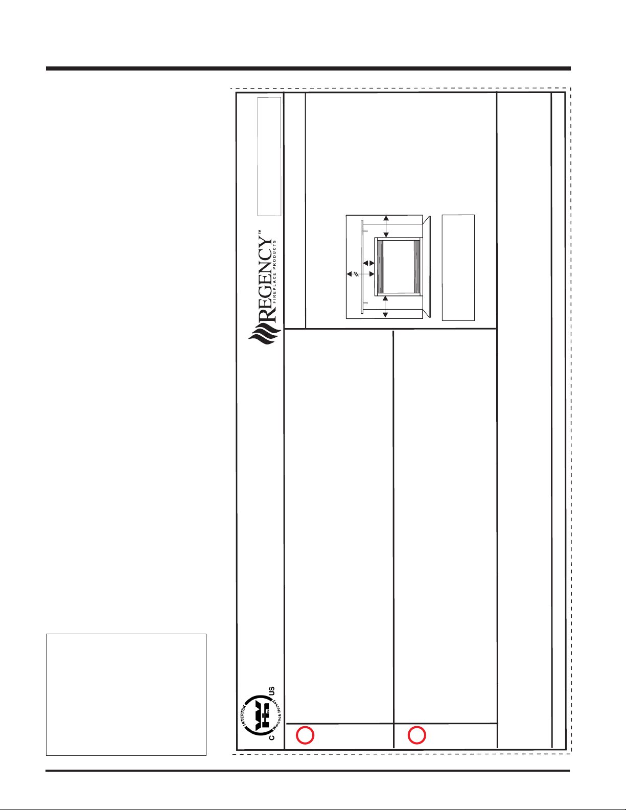
This is a copy of the label that accompanies each
P48-NG and P48-LP Zero Clearance Direct Vent
Gas Fireplace. We have printed a copy of the
contents here for your review. The safety label
is located on the front inside base of the unit,
visible when the bottom louver is open.
NOTE: Regency units are constantly being improved. Check the label on the unit and if there
is a difference, the label on the unit is the correct
one.
Copy of Safety Decal for P48-NG and P48-LP
For the State of Massachusetts, installation
and repair must be done by a plumber or
gasfitter licensed in the Commonwealth of
Massachusetts.
For the State of Massachusetts, flexible
connectors shall not exceed 36 inches in
length.
For the State of Massachusetts, the appliances individual manual shut-off must be a
t-handle type valve.
4
Regency P48 Zero Clearance Direct Vent Gas Fireplace
INSTALLATION
IMPORTANT:
SAVE THESE
INSTRUCTIONS
The P48-NG/P48-LP Direct Vent Fireplace must
be installed in accordance with these instructions. Carefully read all the instructions in this
manual first. Consult the "authority having jurisdiction" to determine the need for a permit prior to
starting the installation. It is the responsibility of the
installer to ensure this fireplace is installed in
compliance with manufacturers instructions and
all applicable codes.
BEFORE YOU START
Safe installation and operation of this appliance
requires common sense, however, we are
required by the Canadian Safety Standards
and ANSI Standards to make you aware of the
following:
INSTALLATION AND REPAIR
SHOULD BE DONE BY AN AUTHORIZED SERVICE PERSON. THE APPLIANCE SHOULD BE INSPECTED
BEFORE USE AND AT LEAST ANNUALLY BY A PROFESSIONAL
SERVICE PERSON. MORE FREQUENT CLEANING MAY BE REQUIRED DUE TO EXCESSIVE LINT
FROM CARPETING, BEDDING MATERIAL, ETC. IT IS IMPERATIVE
THAT CONTROL COMPARTMENTS, BURNERS AND CIRCULATING AIR PASSAGEWAYS OF THE
APPLIANCE BE KEPT CLEAN.
DUE TO HIGH TEMPERATURES,
THE APPLIANCE SHOULD BE LOCATED OUT OF TRAFFIC AND
AWAY FROM FURNITURE AND
DRAPERIES.
WARNING: FAILURE TO INSTALL
THIS APPLIANCE CORRECTLY
WILL VOID YOUR WARRANTY AND
MAY CAUSE A SERIOUS HOUSE
FIRE.
CHILDREN AND ADULTS SHOULD
BE ALERTED TO THE HAZARDS
OF HIGH SURFACE TEMPERATURES, ESPECIALLY THE FIREPLACE GLASS, AND SHOULD
STAY AWAY TO AVOID BURNS OR
CLOTHING IGNITION.
YOUNG CHILDREN SHOULD BE
CAREFULLY SUPERVISED WHEN
THEY ARE IN THE SAME ROOM AS
THE APPLIANCE.
CLOTHING OR OTHER FLAMMABLE MATERIAL SHOULD NOT BE
PLACED ON OR NEAR THE APPLIANCE.
GENERAL SAFETY
INFORMATION
1) The appliance installation must conform
with local codes or, in the absence of local
codes, with the current Canadian or National Gas Codes, CAN1-B149 or ANSI Z223.1
Installation Codes.
2) The appliance when installed, must be electrically grounded in accordance with local
codes, or in the absence of local codes with
the current National Electrical Code, ANSI/
NFPA 70 or CSA C22.1 Canadian Electrical
Code.
3) See general construction and assembly
instructions. The appliance and vent should
be enclosed.
4) This appliance must be connected to the
specified vent and termination cap to the
outside of the building envelope. Never vent
to another room or inside a building. Make
sure that the vent is fitted as per Venting
instructions.
5) Inspect the venting system annually for
blockage and any signs of deterioration.
6) Venting terminals shall not be recessed into
a wall or siding.
7) Any safety glass removed for servicing
must be replaced prior to operating the
appliance.
8) To prevent injury, do not allow anyone who
is unfamiliar with the operation to use the
fireplace.
9) Wear gloves and safety glasses for protection while doing required maintenance.
10)Be aware of electrical wiring locations in
walls and ceilings when cutting holes for
termination.
11)Under no circumstances should this appliance be modified. Parts that have to be
removed for servicing should be replaced
prior to operating this appliance.
12)Installation and any repairs to this appliance
should be done by an authorized service
person. A professional service person
should be called to inspect this appliance
annually. Make it a practice to have all of
your gas appliances checked annually.
13)Do not slam shut or strike the glass door.
14)Under no circumstances should any solid
fuels (wood, paper, cardboard, coal, etc.)
be used in this appliance.
15)The appliance area must be kept clear and
free of combustible materials, (gases and
other flammable vapours and liquids).
Emissions from burning wood or gas could
contain chemicals known to the State of
California to cause cancer, birth defects or
other reproductive harm.
INSTALLATION
CHECKLIST
1) Locate appliance
a) Room location, page 6
b) Clearances to Combustibles, page 7
c) Mantel Clearances, page 8
d) Framing & Finishing Requirements,
page 9
e) Venting Requirements, pages 10-18.
2) Assemble Top Facing Support and Side
Nailing Strips, page 10.
NOTE: must be done before installing
unit into fireplace.
3) Install venting, pages 20-21.
4) Make gas and electrical connections. Test
the pilot. Must be as per diagram. Page 23.
5) Test Gas Pressure. Page 23.
6) Install brick panels (optional), page 24.
7) Install Flush Door Front (Standard) and
optional Flush Gold Trim, page 28.
8) Install Optional Bay Front and optional Bay
Gold Trim, page 29.
9) Install Louvers (Flush or Bay), pages
28-29.
10)Installation of Wall Switch, Remote Control,
or Wall Thermostat, page 31.
11)Final check.
Before leaving this unit with the customer, the
installer must ensure that the appliance is firing
correctly and operation fully explained to
customer.
Regency P48 Zero Clearance Direct Vent Gas Fireplace 5
INSTALLATION
This includes:
1) Clocking the appliance to ensure the correct
firing rate (rate noted on label 51,000 (NG)
Btu/h, 48,000 (LP) Btu/h) after burning appliance for 15 minutes.
2) If required, adjusting the primary air to ensure that the flame does not carbon. First
allow the unit to burn for 15-20 min. to
stabilize.
CAUTION: Any alteration to the product
that causes sooting or carboning that
results in damage is not the responsibil-
ity of the manufacturer.
MANUFACTURED
MOBILE HOME
ADDITIONAL
REQUIREMENTS
1) Ensure that structural members are not cut
or weakened during installation.
2) Ensure proper grounding using the #8
ground lug provided. See page 32.
UNIT SPECIFICATIONS
LOCATING YOUR
GAS STOVE
1) When selecting a location for your stove,
ensure that the clearances outlined on this
page are met.
2) Provide adequate clearances for servicing.
3) The appliance must be installed on a flat,
solid, continuous surface (e.g. wood, metal, concrete). This may be the floor, or
raised up on a platform to enhance its
visual impact. If the appliance is going to be
installed on carpeting, combustible linoleum tile or other combustible material other
than wood flooring, the appliance must be
installed on a metal or wood panel extending the full width and depth of the appliance.
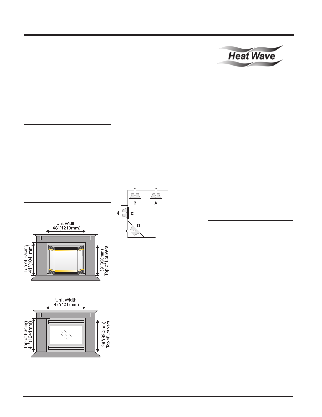
4) The P48 Direct Vent Gas Fireplace can be
installed in a recessed position or framed
out into the room as in A, B, C, D. See
Diagram 1.
Diagram 1
A) Flat on Wall
B) Flat on Wall Corner
C) Recessed into
Wall/Alcove
D) Corner
OPTIONAL
DUCT SYSTEM
KIT #946-556
The HeatWave Air Duct Kit increases the
effectiveness of your fireplace by dispersing
warm air from the fireplace to remote locations
in the same room or other rooms in your home.
Up to two kits may be installed on the fireplace.
Please Note: Only 1 HeatWave kit may be
operated at one time. This includes the internal
blower option as well.
OPTIONAL
HEAT RELEASE
KIT #946-570
The Heat Release Kit expels warm air from the
fireplace to the outside of the building, allowing
the fireplace to be operated with less heat
entering the room. The kit may be used on either
the left or right side.
HEARTH
5) This appliance is Listed for bedroom instal-
lations when used with a Listed Millivolt
Thermostat. Some areas may have further
requirements, check local codes before
installation.
6) The P48 Direct Vent Gas Fireplace is approved for alcove installations, which meet
the clearances listed on this page.
7) We recommend that you plan your installation on paper using exact measurements
for clearances and floor protection before
actually installing this appliance. Have an
authorized inspector, dealer, or installer
review your plans before installation.
Note: For vent terminations see page 11.
A hearth is not mandatory, but is recommended
for aesthetics and for added safety.
6
Regency P48 Zero Clearance Direct Vent Gas Fireplace
INSTALLATION
CLEARANCES
The clearances listed below are Minimum distances unless otherwise stated:
A major cause of chimney related fires is failure to maintain required clearances (air space) to combustible materials. It is of
the greatest importance that this fireplace and vent system be installed only in accordance with these instructions.
Clearance to Combustibles from:
Back 0" (0mm)
Side 0" (0mm)
Floor 0" (0mm)
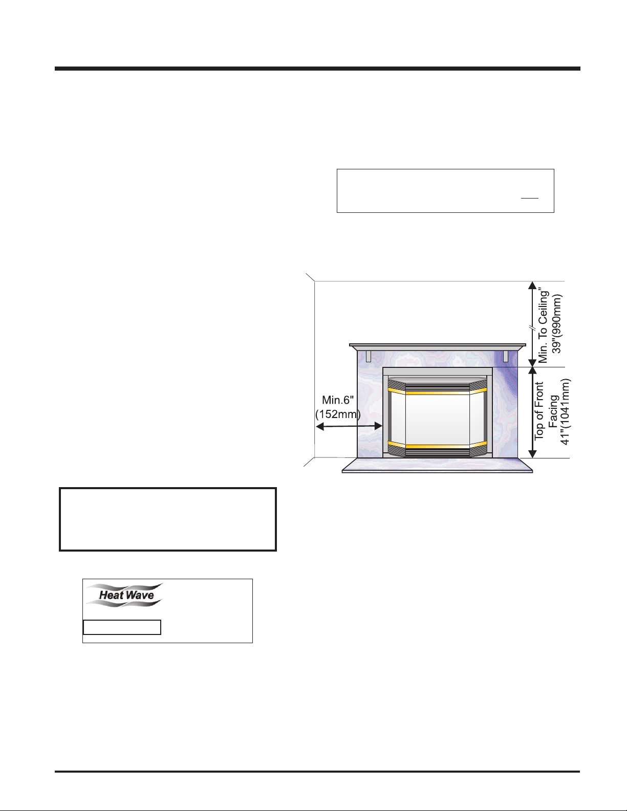
Minimum Clearance from Top of Front Facing:
Mantel min. 8" (203mm)
Ceiling 39" (990mm) from top of front facing above louvers.
Side Wall:
6" (152mm)
Horizontal Vent Clearances:
Top 2-1/2" (64mm)
Side 1-1/2" (38mm)
Bottom 1-1/2" (38mm)
Vertical Vent Clearances:
1-1/4" (32mm)
Alcove Clearances:
Max. Depth 36" (914mm)
Min. Width 60" (1524mm)
Min. Height 80" (2032mm)
The top, back and sides of the fireplace are defined by
Caution Requirements
standoffs. The metal ends of the standoff may NOT be
recessed into combustible construction.
if these clearances (air space) to combustible materials
Fire hazard is an extreme risk
are not adhered to. It is of greatest importance that this
fireplace and vent system be installed only in
accordance with these instructions.
Heat Release Kit
Regency P48 Zero Clearance Direct Vent Gas Fireplace 7
WARNING
The HeatWave Duct Kit
and the Heat Release
Kit have different clearance and framin requirements, check the Heat-
Wave and Heat Release
manual for details.
INSTALLATION
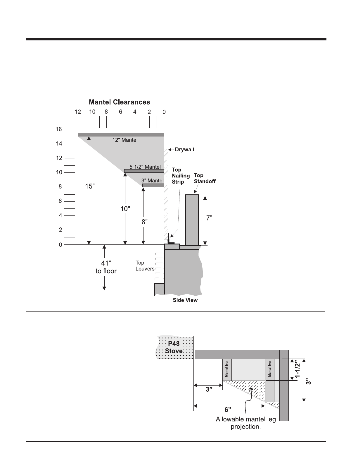
MANTELS
Because of the extreme heat this fireplace emits, the mantel clearances are critical. Combustible mantel clearances from louver are
shown in the diagram below.
Note: A non-combustible mantel may be installed at a lower height if the framing is made of metal studs covered with a non-
combustible board.
This drawing is to scale at 1:6 (one inch = 6
inches)
Mantel can be installed anywhere in shaded
area using the above scale for units with the
Flush Front and with the optional Bay Front.
Note: Ensure the paint that is used on
the mantel and the facing is "heat
resistant" or the paint may discolour.
MANTEL LEG CLEARANCES
Combustible mantel leg clearances as per diagram:
8
Maximum
1-1/2" projection at 3"
minimum clearance.
Regency P48 Zero Clearance Direct Vent Gas Fireplace
FRAMING & FINISHING
1) Determine the total thickness of facing material (eg. drywall plus
ceramic tiles) to allow the finished surface to be flush with the front
of the unit. Total facing thickness can vary from 1/2" (13mm) to
1-1/4" (32mm) thick.
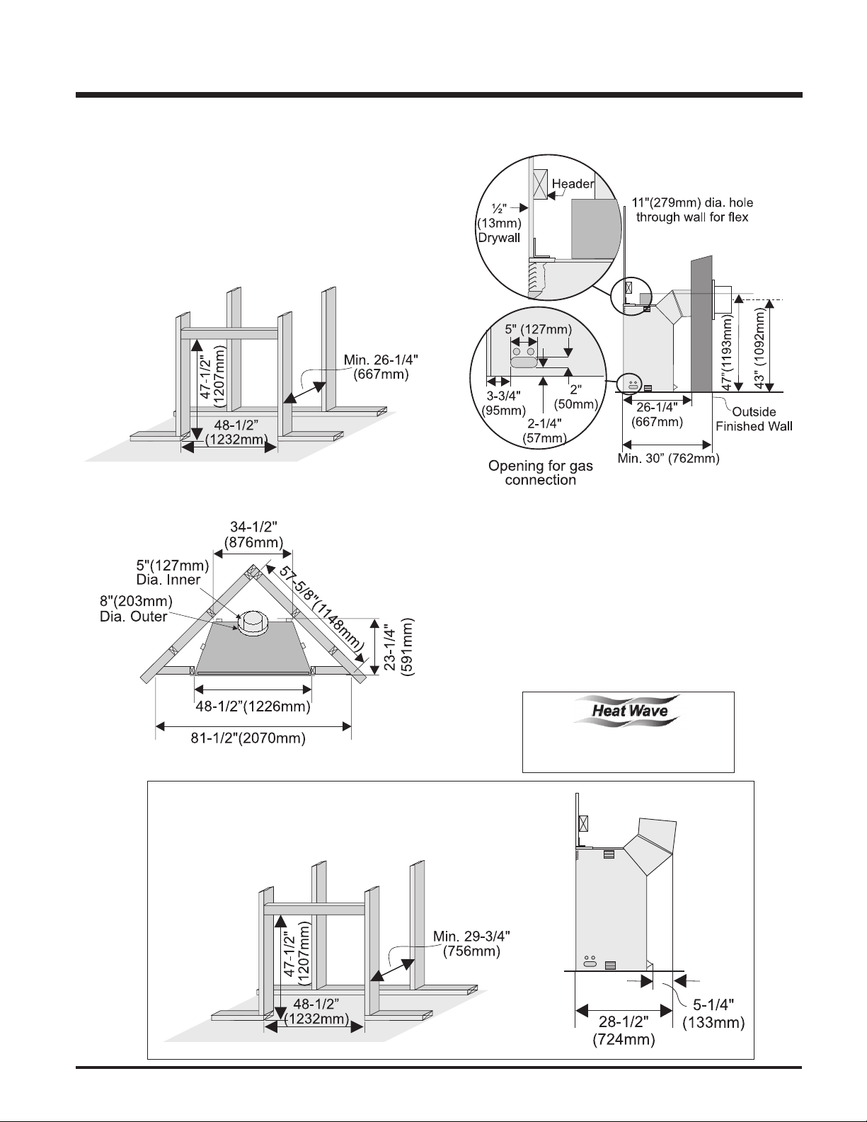
2) Frame in the enclosure for the unit with framing material. The framed
opening for the assembled kit is 47-1/2" high x 48-1/2" wide x
26-1/4" deep (1207mm H x 1232mm W x 667mm D). See Diagram 1.
INSTALLATION
Diagram 1
Note: 43" (1092mm) is the minimum height for flex termination
and Simpson Dura-Vent terminations.
3) For exterior walls, insulate the enclosure to the same degree as the
rest of the house, apply vapour barrier and drywall, as per local
installation codes. (Do not insulate the fireplace itself.)
4) The unit does not have to be completely enclosed in a chase. The
clearance on top of the unit from the top standoffs is 0" so
combustible building materials can be laid directly on top of the
standoffs. You must maintain clearances from the vent to combustible materials: See page 7. Combustible materials can be laid against
the side and back standoffs and the stove base.
The HeatWave Duct Kit has different
clearance and framing requirements,
check the HeatWave manual for details.
IMPORTANT
When installing the unit with any vertical venting off the top of the
unit as shown, the minimum framing depth changes accordingly.
Regency P48 Zero Clearance Direct Vent Gas Fireplace 9
INSTALLATION
UNIT ASSEMBLY
PRIOR TO
INSTALLATION
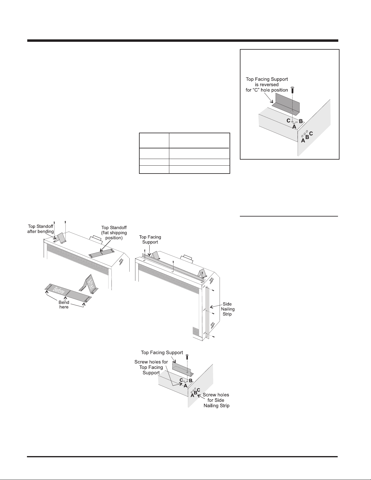
The Top Facing Support, the Side Nailing Strips
and the 2 Top Standoffs must be correctly
positioned and attached to the top before unit
is slipped into position.
Top Standoff Assembly
The top standoffs are shipped in a flat position
and must be folded into shape and attached.
1) Remove the standoffs from the fireplace
top.
2) Take each standoff and bend into the correct shape. Bend up at the bend lines until
the screw holes in the standoff and the prepunched screw holes on the fireplace top
line up.
3) Attach the standoff securely to the top with
2 screws per standoff (on opposite corners).
Top Facing Support and
Side Nailing Strips
Determine the total thickness of facing material
(e.g. drywall plus ceramic tiles) to allow the
finished surface to be flush with the front of the
unit. Total facing thickness can vary from 1/2"
(13mm) to 1-1/4" (32mm) thick.
The Top Facing Support & Side Nailing Strips
can be mounted in 3 different positions depending on the thickness of the facing material.
Screw Facing Material
Position Depth
A 1/2" / 13mm
B 7/8" / 22mm
C* 1-1/4" / 32mm
* For "C" screw position the top facing support
is reversed.
1) Mount Top Facing Support using the 3
supplied screws into the three pre-punched
screw holes on the top front of the unit. Use
hole positions A, B, or C depending on your
facing depth.
"C" Screw Position:
For a facing material depth of 1-1/4"
(32mm), the top facing support must be
reversed.
2) Use the same screw hole position for the
Side Nailing Strips as was used for the Top
Facing Support. Attach each side nailing
strip using 3 screws.
VENTING
INTRODUCTION
The P48 uses the "balanced flue" technology
Co Axial system. The inner liner vents products
of combustion to the outside while the outer
liner draws outside combustion air into the
combustion chamber thereby eliminating the
need to use heated room air for combustion and
losing warm room air up the chimney.
Note: These flue pipes must not be con-
nected to any other appliance.
The gas appliance and vent system must be
vented directly to the outside of the building,
and never be attached to a chimney serving a
separate solid fuel or gas burning appliance.
Each direct vent gas appliance must use it's
own separate vent system. Common vent
systems are prohibited.
10
Regency P48 Zero Clearance Direct Vent Gas Fireplace
INSTALLATION
.
B
B
B
B
A
C
V
V
V
V
V
V
V
A
A
V
Fixed
Fixed
Openable
Closed
Closed
Openable
N
L
B
E
B
M
D
F
K
H
j
Vertical
Termination
V
Vent terminal
Area where terminal is not permited
A
Air supply outlet
24"
V
A
G
Inside
corner detail
V
24"
18"
Vertical
Termination
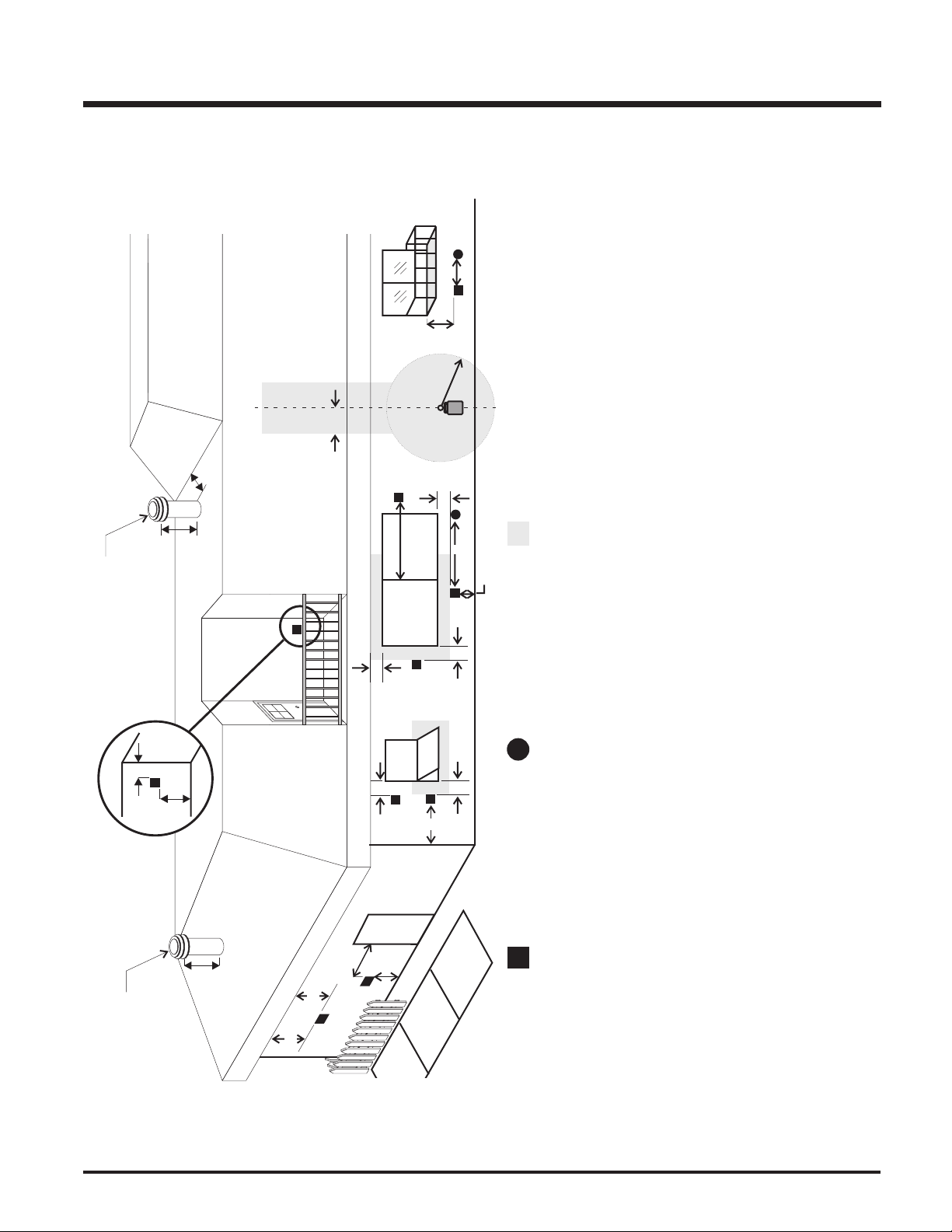
EXTERIOR VENT TERMINATION REQUIREMENTS
the centerline of the regulator.
any other appliance *(12"/30cm)
*(min. 84"/2.1m)
L= Clearance to a mechanical air supply inlet *(min. 72"/1.8m)
M= Clearance above paved sidewalk or a paved driveway located on public property
N= Clearance under veranda, porch, deck, or balcony *(min. 23"/58cm)
H = Not to be installed above a meter/regulator assembly within (3'/90cm) horizontally from
J= Clearance to service regulator vent outlet *(min 36"/90cm)
K= Clearance to non-mechanical air supply inlet to building or the combustion air inlet to
Regency P48 Zero Clearance Direct Vent Gas Fireplace 11
distance of 24"/60cm (min. 23"/58cm) (32"/81cm with vinyl siding)
A= Clearance above grade, veranda, porch, deck, or balcony *(min. 12"/30cm)
B= Clearance to window or door that may be opened *(12"/30cm)
C= Clearance to permanently closed window *(min. 12"/30cm)
D= Vertical clearance to ventilated soffit located above the terminal within a horizontal
E= Clearance to unventilated soffit (min. 23"/58cm) (32"/81cm with vinyl siding)
F= Clearance to outside corner: (13"/33cm)
G= Clearance to inside corner: (13"/33cm)
Note:
- A vent shall not terminate directly above a sidewalk or paved driveway which is located between two single family dwellings and serves both dwellings.
- Only permitted if veranda, porch, deck, or balcony is fully open on a minimum of two sides beneath the floor.
- If the vent termination is accessible, a certified guard shall be installed.
* As specified in CGA B149 Installation Code. Note: Local codes or regulations may require different clearances.
INSTALLATION
VENTING
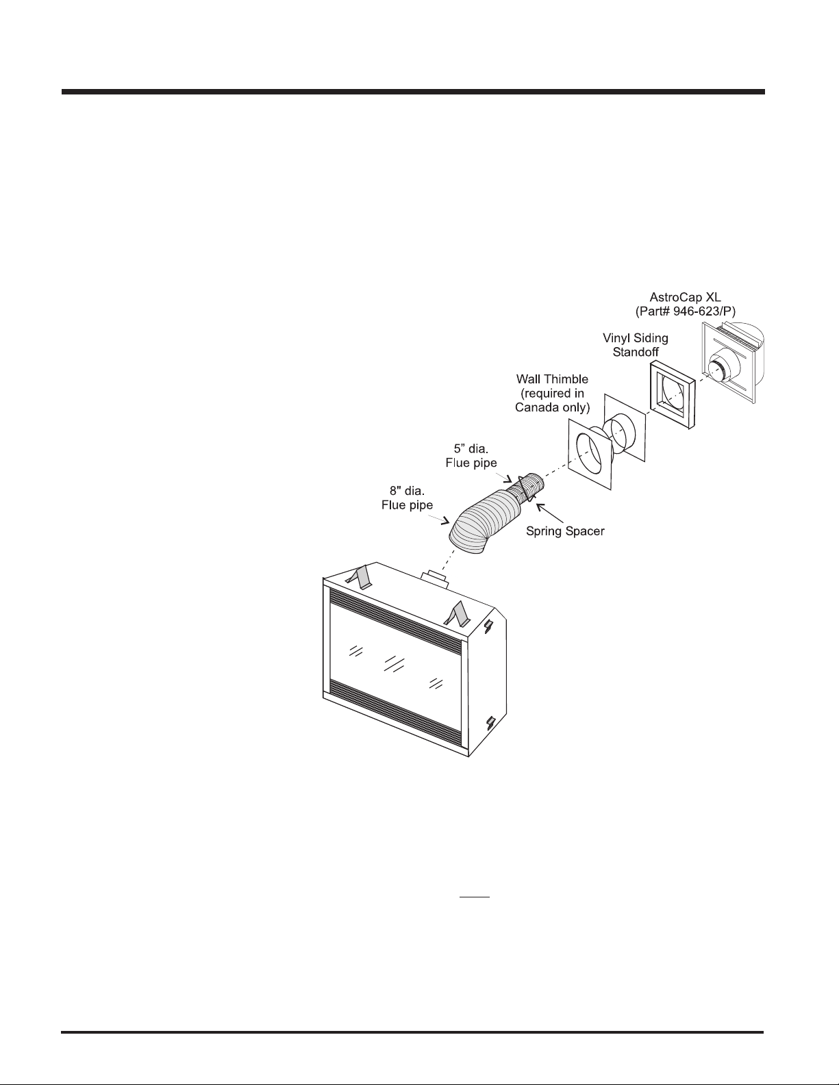
Regency Direct Vent System (Flex) Horizontal
Terminations Only
These venting systems, in combination with the P48 Direct Vent Gas Fireplace, have been tested and listed as a direct vent heater system by Warnock
Hersey. The location of the termination cap must conform to the requirements in the Vent Terminal Locations diagram on page 11.
Regency Direct Vent (Flex) System Termination Kit (Part# 946-615) includes all the parts
needed to install the P48 with a maximum run
of 4 feet.
1) 8" dia. flexible liner (4 ft. length)
2) 5" dia. flexible liner (4 ft. length)
3) spring spacers (4)
4) thimble (2)
5) AstroCap XL termination cap (1)
6) screws (12)
7) tube of Mill Pac (1)
8) plated screws (8)
9) screws #8 x 1-1/2" Drill Point, Stainless Steel (4)
10)vinyl siding standoff
If longer runs are needed, the Regency Direct
Vent system (Flex) Part# 946-616 includes all
the parts needed to install the P48 with a
maximum 10' run.
1) 8" dia. flexible liner (10 ft. length)
2) 5" dia. flexible liner (10 ft. length)
3) spring spacers (7)
4) thimble (2)
5) AstroCap XL termination cap (1)
6) screws (12)
7) tube of Mill Pac (1)
8) plated screws (8)
9) screws #8 x 1-1/2" Drill Point, Stainless Steel (4)
10)vinyl siding standoff
Notes:
1) Liner sections should be continuous without any joints or seams.
2) Only Flex pipe purchased from Regency may be used for Flex installations.
3) If you are installing the P48 into a Regency Mantel Kit, use the minimum horizontal vent height (centre-line of 43"). Remem ber
to include the mantel base in your calculations and to maintain the 2-1/2" clearance to the underside of the mantel top.
12
Regency P48 Zero Clearance Direct Vent Gas Fireplace
INSTALLATION
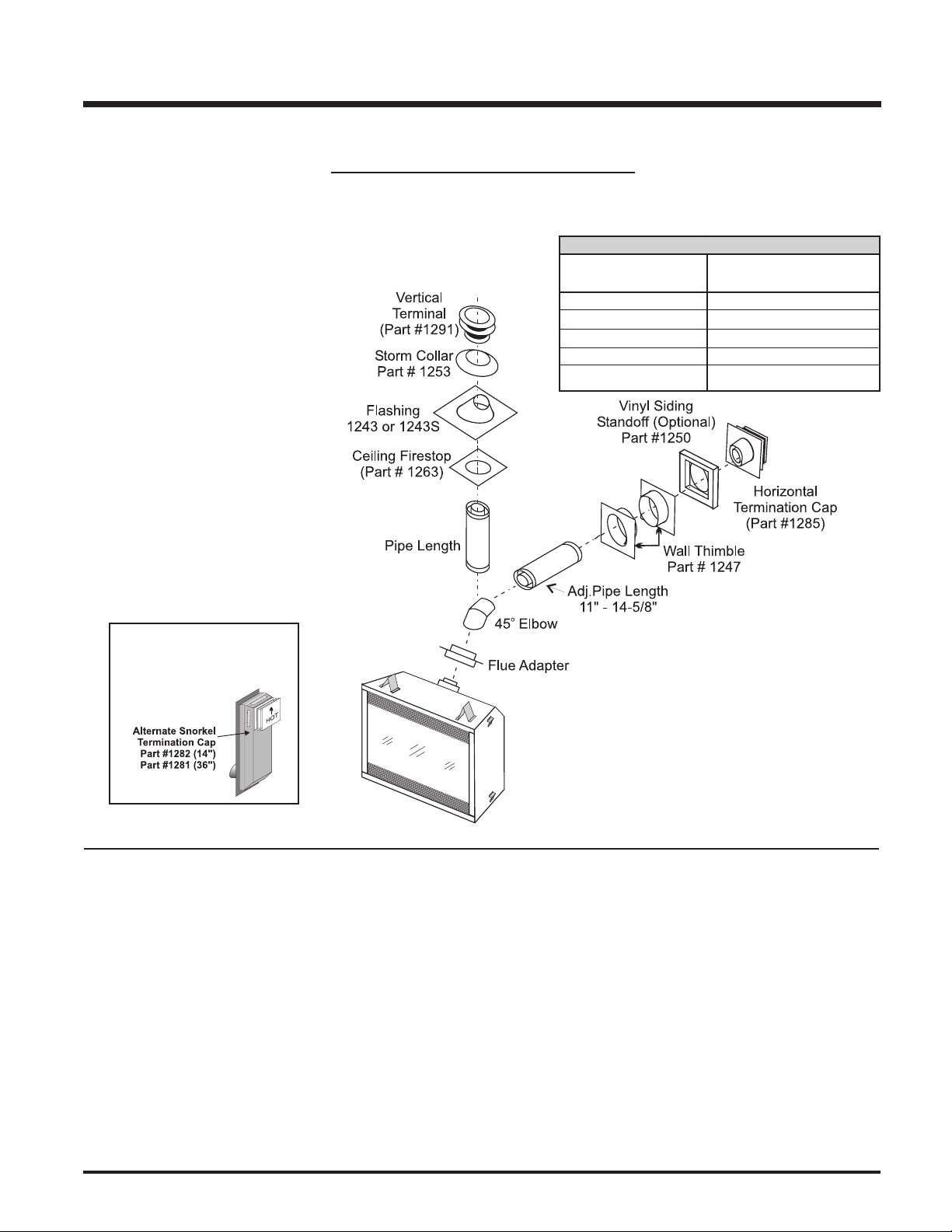
SIMPSON DURA-VENT VENTING
Horizontal or Vertical Terminations
The Simpson Dura-Vent Direct Vent System offers a complete line of component parts for installation of both horizontal and vertical installations.
Many items are offered in decorative black, as well as galvanized finish. We recommend using the galvanized finish for installation with the P48.
The minimum components required for a basic
horizontal termination are:
1 Horizontal Termination Cap
o
Elbow
145
1 Flue Adaptor
1 Wall Thimble
1 Length of pipe to suit wall thickness
(see chart)
Wall thickness is measured from the back
standoffs to the inside mounting surface of
termination cap. For siding other than vinyl
furring strips may be used, instead of the vinyl
siding standoff, to create a level surface to
mount the vent terminal. The Terminal must not
be recessed into siding. Measure the wall
thickness including furring strips.
If a Vinyl Siding Standoff is required (it must be
used with vinyl siding), measure to outside
surface of wall without siding and add 2
inches.
Alternate
Horizontal Termination
Caps
Flat Wall Installation
Wall Thickness Vent Length
(inches) Required (inches)
4" - 5-1/2" none
7" - 8-1/2" 6"
10" - 11-1/2" 9"
9" - 14-1/2" 12"
15" - 23-1/2" 11" - 14-5/8" Adj. Pipe
SIMPSON DURA-VENT VENTING
COMPONENTS LIST
Part # Description
1208B 6" Pipe Length-Black
1207B 9" Pipe Length-Black
1206 12" Pipe Length Galv.
1206B 12" Pipe Length-Black
1204 24" Pipe Length Galv.
1204B 24" Pipe Length-Black
1203 36" Pipe Length Galv.
1203B 36" Pipe Length-Black
1202 48" Pipe Length Galv.
1202B 48" Pipe Length-Black
1211B 11"-14 5/8" Adj./P/L-Black
1217B 17"- 24" Adj. Length Black
Regency P48 Zero Clearance Direct Vent Gas Fireplace 13
Part # Description
1245 45O Elbow Galv.
1245B 45O Elbow-Black
1245G 45O Elbow-Swivel Galv.
1245BG 45O Elbow-Swivel-Black
1290 90O Elbow Galv.
1290B 90O Elbow-Black
1290G 90O Elbow-Swivel Galv.
1290BG 90O Elbow-Swivel-Black
1291 High Wind Term. Cap (Vertical Only)
1285 Horiz.Sq.HighWind Trm.Cap (Only)
1282 Snorkel-14" Rise Term.Cap
Part # Description
1281 Snorkel-36" Rise Term.Cap
1240 Wall Thimble-Suprt/Box
1241 Cathdrl/Clng-Sprt/Box
3951 Brass Trim for Wall Thimble/Ceiling Support
1263 Firestop Spacer
1243 Flashing 0/12-6/12
1243S Flashing 7/12-12/12
1253 Storm Collar
1250 Vinyl Siding Standoff
1288 Wall Strap
1247 Wall Thimble
Parts not supplied by Dura-Vent
370-994 Dura-Vent Flue Adaptor
INSTALLATION
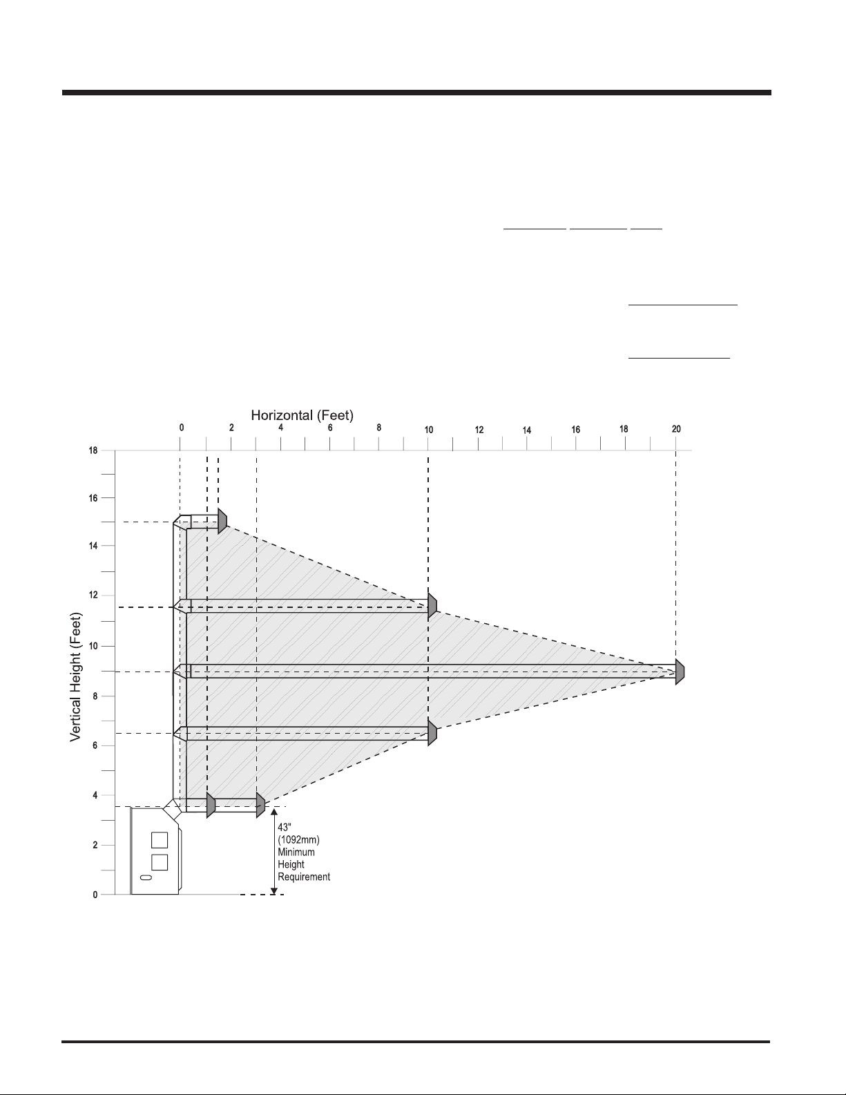
VENTING ARRANGEMENTS - HORIZONTAL TERMINATIONS
SIMPSON DURA-VENT DIRECT VENT GS SYSTEM and
REGENCY DIRECT VENT SYSTEM (FLEX)
(Propane & Natural Gas)
The diagram shows all allowable combinations of vertical runs with horizontal terminations, using one 45o and one 90o elbow (two 45o elbows equal
one 90o elbow).
Note: Must use optional flue adapter (Part # 370-994) when using Simpson Dura-Vent pipe. (Refer to page 13.)
Simpson Dura-Vent
5" inner diameter
8" outer diameter
Regency Flex Vent
5" inner diameter
8" outer diameter
• Maintain clearances to combustibles as listed on pages 6 to 9.
• Horizontal vent must be supported every 3 feet.
• Firestops are required at each floor level and whenever passing through a wall.
14
Regency P48 Zero Clearance Direct Vent Gas Fireplace
A vent guard should be used whenever the termination is lower than the
specified minimum or as per local
codes.
Note: Regency Direct Vent System
(Flex) is only approved for horizontal terminations.
INSTALLATION
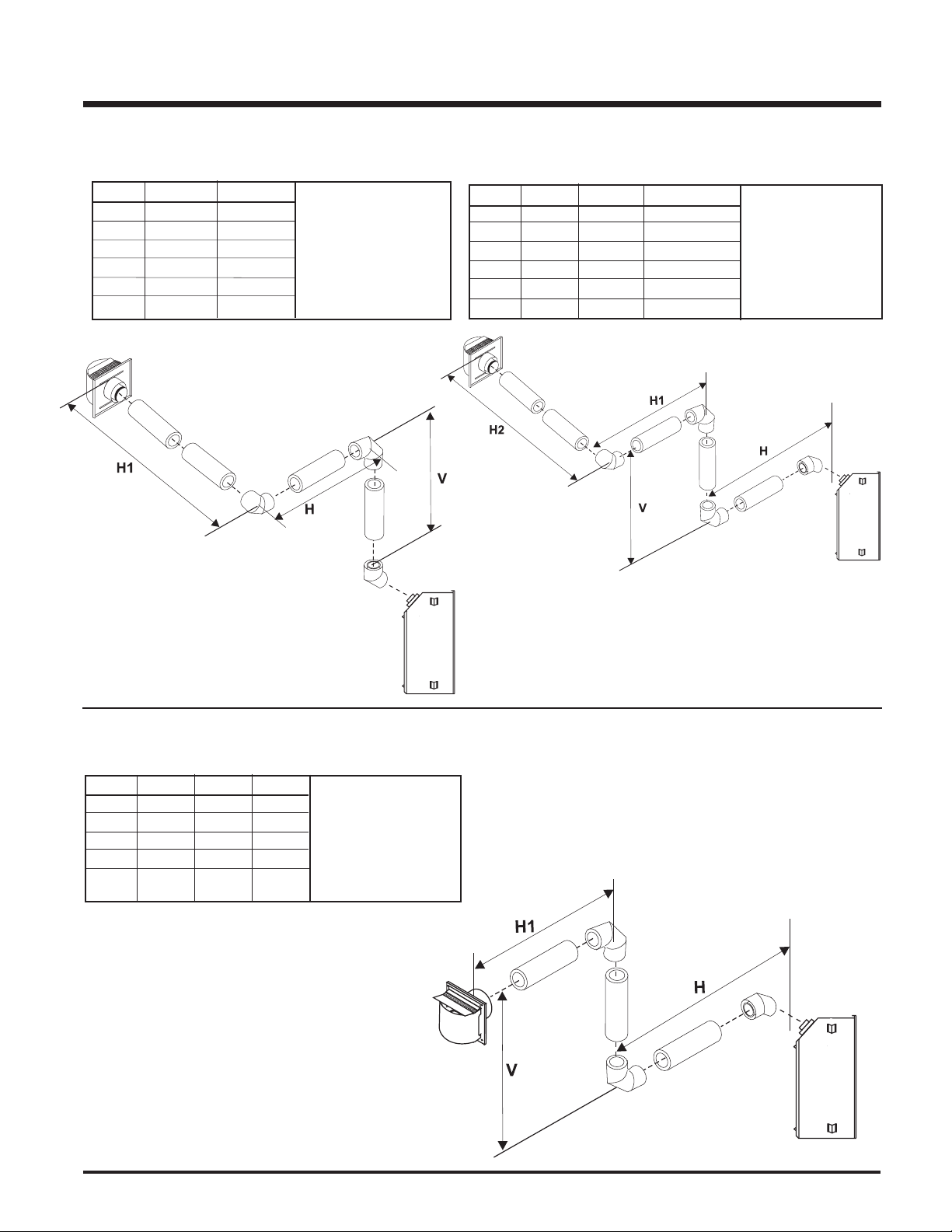
Horizontal Venting with Two (2) 90o Elbows
One 90o elbow = Two 45o elbows.
Option V H + H1
A) 1' Min. 3' Max.
B) 2' Min. 4' Max.
C) 3' Min. 5' Max.
D) 4' Min. 6' Max.
E) 5' Min. 7' Max.
F) 6' Min. 8' Max.
With these options, maximum total pipe length is 30
feet with minimum of 6 feet
total vertical and maximum
8 feet total horizontal.
Please note minimum 1
foot between 90o elbows
is required.
Horizontal Venting with Three (3) 90o Elbows
One 90o elbow = Two 45o elbows.
Option H V H + H1 + H2
A) 1 Max. 1' Min. 3' Max.
B) 2' Max. 3' Min. 5' Max.
C) 3' Max. 5' Min. 6' Max.
D) 4' Max. 7' Min. 7' Max.
E) 5' Max. 9' Min. 8' Max.
F) 6' Max. 11' Min. 9' Max.
With these options, max.
total pipe length is 30
feet with min. of 11 feet
total vertical and max. 9
feet total horizontal.
Please note min.
1 foot between 90
elbows is required.
o
One 90o elbow = Two 45o elbows.
Option H V H + H1
A) 1' Max. 1' Min. 3' Max.
B) 2' Max. 2' Min. 5' Max.
C) 3' Max. 4' Min. 6' Max.
D) 4' Max. 6' Min. 7' Max.
E) 5' Max. 8' Min. 8' Max.
Horizontal Venting with Two (2) 90o Elbows
With these options, max.
total pipe length is 30 feet
with min. of 8 feet total
vertical and max. 8 feet
total horizontal.
Please note min. 1 foot
between 90o elbows is
required.
Regency P48 Zero Clearance Direct Vent Gas Fireplace 15
 Loading...